

Page 1
SERVICE MANUAL
TO ALPINE Home Page
RDS MP3/WMA CD Receiver
CDA-9853R
3 / 05-A
68E38373S01
Page 2
<Cautions for Safe Repair Work>
r
s
- 2 -
The following cautions will prevent accidents in the workplace and will ensure safe products.
*The symbols indicate caution is needed to prevent injuries and damage to property.
The symbols and their meanings follow.
Warning
Caution
*The following symbols indicate two levels of cautions.
When you see this symbol, you have to be very careful.
When you see this symbol, you have to follow the instructions there.
If you ignore this symbol and handle the product incorrectly or unsafely,
serious injury or death may result.
If you ignore this symbol and handle the product incorrectly or unsafely,
injury or only material damage may result.
Warning
Do not look squarely into the laser light
coming from the pickup. Always use a designated fuse.
You may loose you sight. Use of an incorrect fuse may result in a fire.
Caution
Do not allow wiring to be caught in the Battery Caution
screw/chassis. Use the designated battery.
If wiring is caught in the screw/chassis, it may Confirm the correct polarity and seat of the
cause a short circuit, resulting in a fire. battery.
Fuse Caution
An incorrect battery or an improperly connected
or seated battery may result in a fire.
High Temperature Caution Designated Parts Caution
Touching the heat sink may cause severe burns. Look up the part list and ensure that only
designated parts are used to prevent problems or
accidents.
Reverse Power Supply Connections o
Misconnections Caution Ensure that the wiring is correct when rewiring to
Reverse power supply connections or prevent problems with ignition/breakdown.
misconnections may cause ignition problems and
smoke may result.
Soldering Caution Wear Glove
Hot solder from solder splash may cause severe Wear gloves to prevent electrical shocks or injury
burns. from the end face of the metal.
Wiring Caution
Page 3

Contents
- 3 -
CDA-9853R
Packing Assembly Parts List
Packing Method View
Specifications
5 , 6
Extension Cable
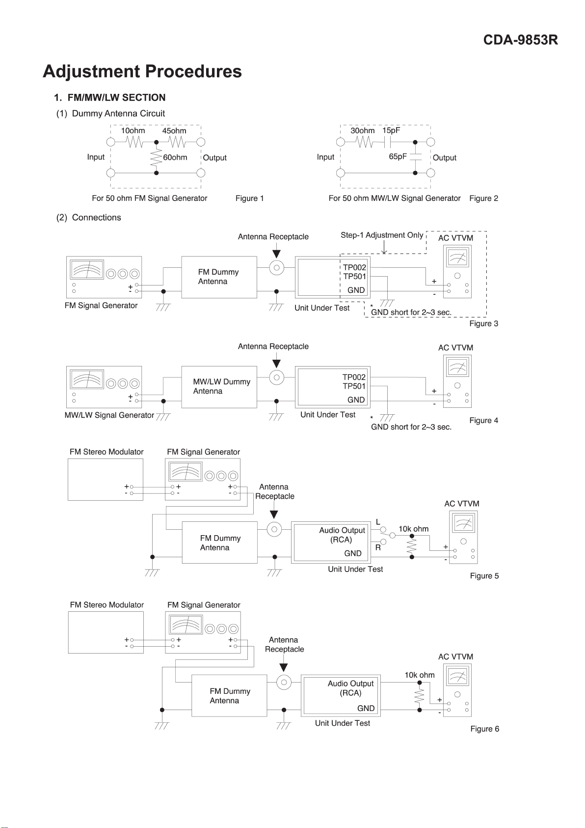
Adjustment Procedures
8 to 11
Block Diagram
Parts Layout on P.W.Boards and Wiring Diagram
Schematic Diagram
Terminal Voltage of IC/TR
Description of IC Terminal
Exploded View (Cabinet)
13 to 16
17 to 22
23 to 36
37 to 42
43 , 44
4
4
7
12
Exploded View (CD Deck Mechanism) (DP23S8DA)
NOTE : Due to continuing product improvement, specifications and designs are subject to
change without notice.
45
Page 4
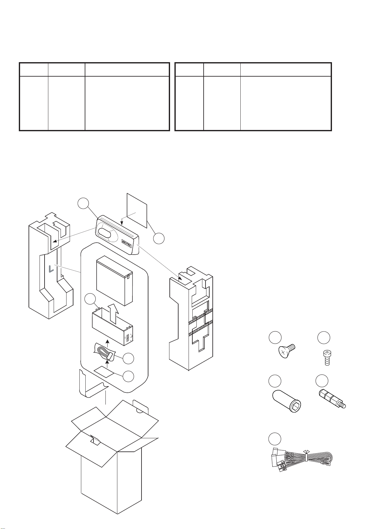
Packing Assembly Parts List
TO CONTENTS
- 4 -
CDA-9853R
Symbol SymbolDescription
Part No. Part No.
No. No.
101 15D00529K02 CASE,INNER 103-4 03A60836Y01 SCR,CUS 5X7 ZN A
102 15D01798K03 CARRYING,CASE 104 09-02252Z01 ASSY,ANIC-0007-01A
103-1 03S60820Y16 SCR,MCH 5X8 ZN A 105 68-02278Z08 O/M AOEU AODL
103-2 03S60824Y01 SCR,WEV 1.7X4 ZN A
103-3 36A02449K01 CAP,RUBBER(A)
Packing Method View
102
105
Description
101
BOTTOM Si
d
e
104
103
103
103
104
-1
X4
-3
X1
103
103
-2
X1
-4
X1
X1
Page 5

CDA-9853R
TO CONTENTS
- 5 -
Specifications
< FM RADIO >
Intermediate Frequency ........................................................................................................................ 10.7±0.1MHz
Frequency Range ........................................................................................................................... 87.5 to 108.0MHz
Usable Sensitivity (30dB S/N, Mono, at 98.1MHz) ......................................................................................... 20.2dBf
-3dB Limiting Sensitivity (at 98.1MHz) ........................................................................................................... 20.2dBf
Residual Noise (Ref. 400Hz (narrow), at 98.1MHz) ...................................................................................... 30±10dB
S/N Ratio (at 98.1MHz) ......................................................................................................................... Stereo : 50dB
Mono : 55dB
Image Rejection (at 106.1MHz) .......................................................................................................................... 40dB
IF Rejection (at 90.1MHz) .................................................................................................................................. 60dB
Distortion (Input 60dBu, at 98.1MHz) ................................................................................................................. 1.0%
Frequency Response (Ref. 400Hz, at 98.1MHz) ................................................................................ 100Hz : 0±3dB
10kHz : -10±3dB
Stereo Separation (1kHz, at 98.1MHz) .............................................................................................................. 20dB
PS Sensitivity (at 98.1MHz) ............................................................................................................................ 36.2dBf
< MW RADIO >
Intermediate Frequency ....................................................................................................................... 1st : 10.7MHz
2nd : 450kHz
Frequency Range ............................................................................................................................. 531 to 1,602kHz
Usable Sensitivity (20dB S/N, at 999kHz) .......................................................................................................... 36dB
S/N Ratio (at 999kHz) ........................................................................................................................................ 44dB
Image Rejection (at 1,404kHz) .............................................................................................................. 2nd IF : 50dB
IF Rejection (at 603kHz) ........................................................................................................................ 2nd IF : 60dB
Distortion (at 999kHz) ......................................................................................................................................... 1.5%
Frequency Response (Ref. 400Hz, at 999kHz) .................................................................................. 100Hz : -3±4dB
2.5kHz : -5 +3/-5dB
< LW RADIO >
Intermediate Frequency ....................................................................................................................... 1st : 10.7MHz
2nd : 450kHz
Frequency Range ................................................................................................................................. 153 to 281kHz
Usable Sensitivity (20dB S/N, at 216kHz) .......................................................................................................... 42dB
S/N Ratio (at 216kHz) ........................................................................................................................................ 44dB
Image Rejection (at 270kHz) ................................................................................................................. 2nd IF : 50dB
IF Rejection (at 162kHz) ........................................................................................................................ 2nd IF : 50dB
Distortion (at 216kHz) ......................................................................................................................................... 1.5%
Frequency Response (Ref. 400Hz, at 216kHz) .................................................................................. 100Hz : -3±4dB
2.5kHz : -5 +3/-5dB
< CD SECTION >
System ....................................................................................................................... Optical (Compact Disc System)
Channel Balance (1kHz) ........................................................................................................ CD : TCD-782 : 0±3dB
MP3 : SCD-5100 (FOLDER4-128kbps) : 0±3dB
WMA : SCD-5100 (FOLDER10-128kbps) : 0±3dB
Distortion (1kHz) ........................................................................................................................ CD : TCD-782 : 0.1%
MP3 : SCD-5100 (FOLDER4-128kbps) : 0.1%
WMA : SCD-5100 (FOLDER10-128kbps) : 0.1%
Page 6

CDA-9853R
TO CONTENTS
- 6 -
Frequency Response (Ref. 1kHz, 0dB) ....................................................................... CD : TCD-782 : 17Hz : 0±3dB
127Hz : 0±2dB
10.007kHz : 0±2dB
19.997kHz : -2±4dB
MP3 : SCD-5100 (FOLDER4-128kbps) : 17Hz : 0±3dB
127Hz : 0±2dB
10.007kHz : 0±2dB
19.997kHz : -2±4dB
WMA : SCD-5100 (FOLDER10-128kbps) : 17Hz : 0±3dB
127Hz : 0±2dB
10.007kHz : 0±2dB
19.997kHz : -2±4dB
S/N Ratio .................................................................................................................................. CD : TCD-782 : 85dB
MP3 : SCD-5100 (FOLDER4-128kbps) : 85dB
WMA : SCD-5100 (FOLDER10-128kbps) : 85dB
Separation (1kHz) .................................................................................................................... CD : TCD-782 : 55dB
MP3 : SCD-5100 (FOLDER4-128kbps) : 55dB
WMA : SCD-5100 (FOLDER10-128kbps) : 55dB
De-Emphasis (Ref. 1kHz, 0dB) ................................................................................ CD : TCD-782 : 4kHz : -20±3dB
16kHz : -20±3dB
< CD Deck Mechanism >
Test Disc ....................................................................................................................................................... TCD-782
RF Waveform Amplitude .......................................................................................................................... 1.2±0.5Vp-p
Quantity of Jitter ............................................................................................................................. Less than 30nsec
Measurement Angle Range ............................................................................................... Front and Rear : -15°~75°
Right and Left : ±45°
Laser Current ................................................................................................................................. Initial value ±5mA
(The initial value of laser current is indicated on the Flexible Cable.)
< Pickup >
Wave Length .................................................................................................................................................... 795nm
Laser Power .................................................................................................................................................. CLASS I
< GENERAL >
Power Supply ............................................................................................................................................... DC14.4V
Power Output (TCD-782 (1kHz, 0dB), T.H.D. 10%) / Impedance .................................................... 17W / ch / 4 ohm
Pre Output (TCD-782 (1kHz, 0dB), T.H.D. 1%) / Impedance ............................................ 6 +3/-2dBV / ch / 10k ohm
Back Up Current (ACC-OFF After 1 minute) ....................................................................................................... 5mA
Dimensions (W x H x D) ................................................................................................ Chassis : 178 x 50 x 160mm
Nose : 188 x 58 x 24.6mm
Weight ................................................................................................................................................................ 1.6kg
NOTE : Due to Continuing product improvement, specifications and designs are subject to change without notice.
Page 7
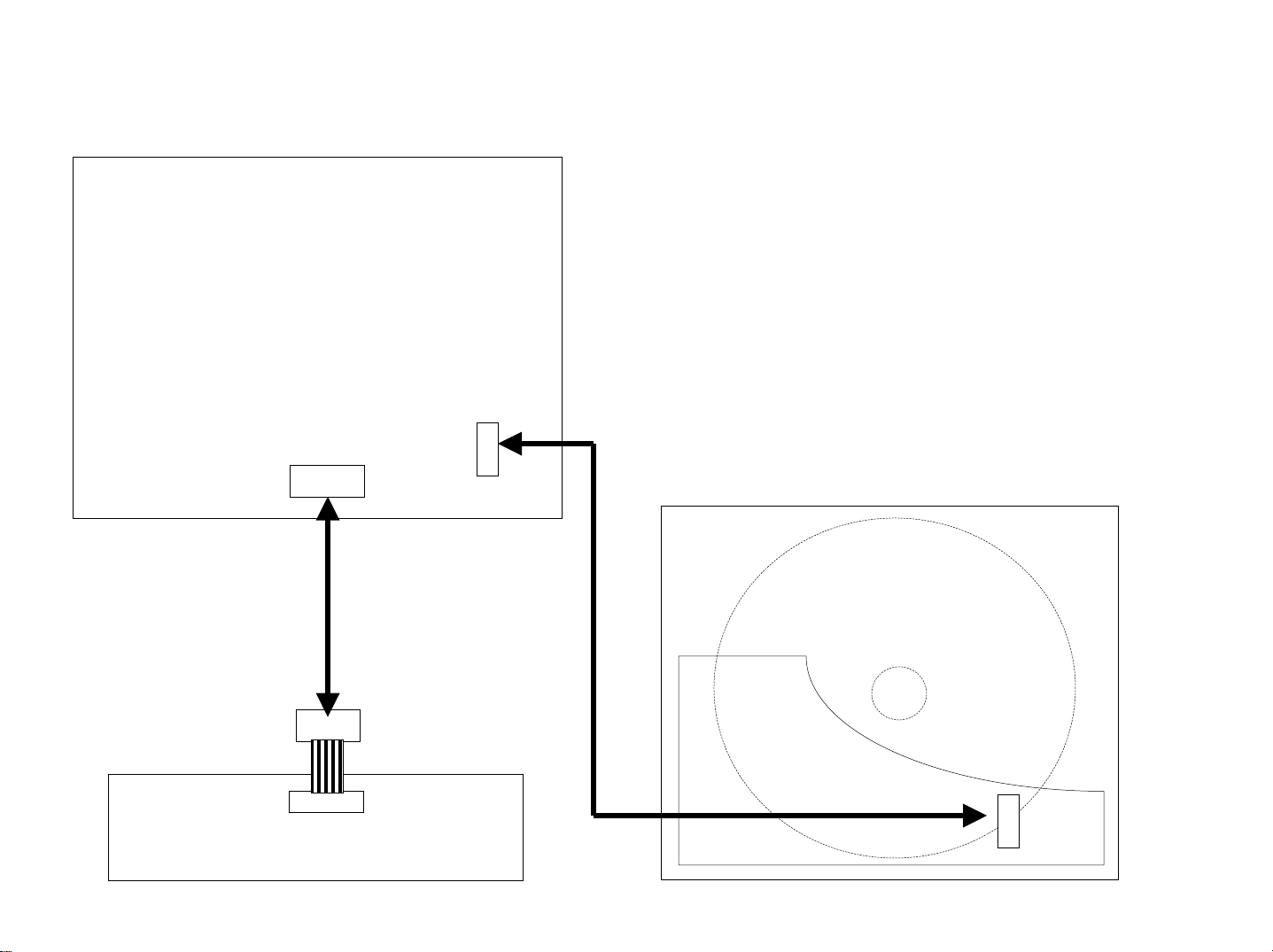
Extension Cable
TO CONTENTS
- 7 -
*Always connect the Extension Cable when making checks of voltage and repair.
MAIN P.W.Board
CDA-9853R
(1) 01E36492S01
(2) 01E29154S01
CB101
FRONT
P.W.Board
CB501
(1)
CH401
CD Deck Mechanism
(DP23S8DA)
(2)
CB104
Page 8
- 8 -
TO CONTENTS
Page 9
(3) Control Settings
- 9 -
TO CONTENTS
Power Switch .............................................. ON Band Switch .............................. FM/MW/LW
Fader Control ........................... Center Position T-CORR ...................................... Non Effect
Balance Control ....................... Center Position EQ ....................................................... FLAT
Treble Control .......................... Center Position DEMO ................................................... OFF
Bass Contro ............................. Center Position Others ................................................... OFF
MX ................................................... Non Effect
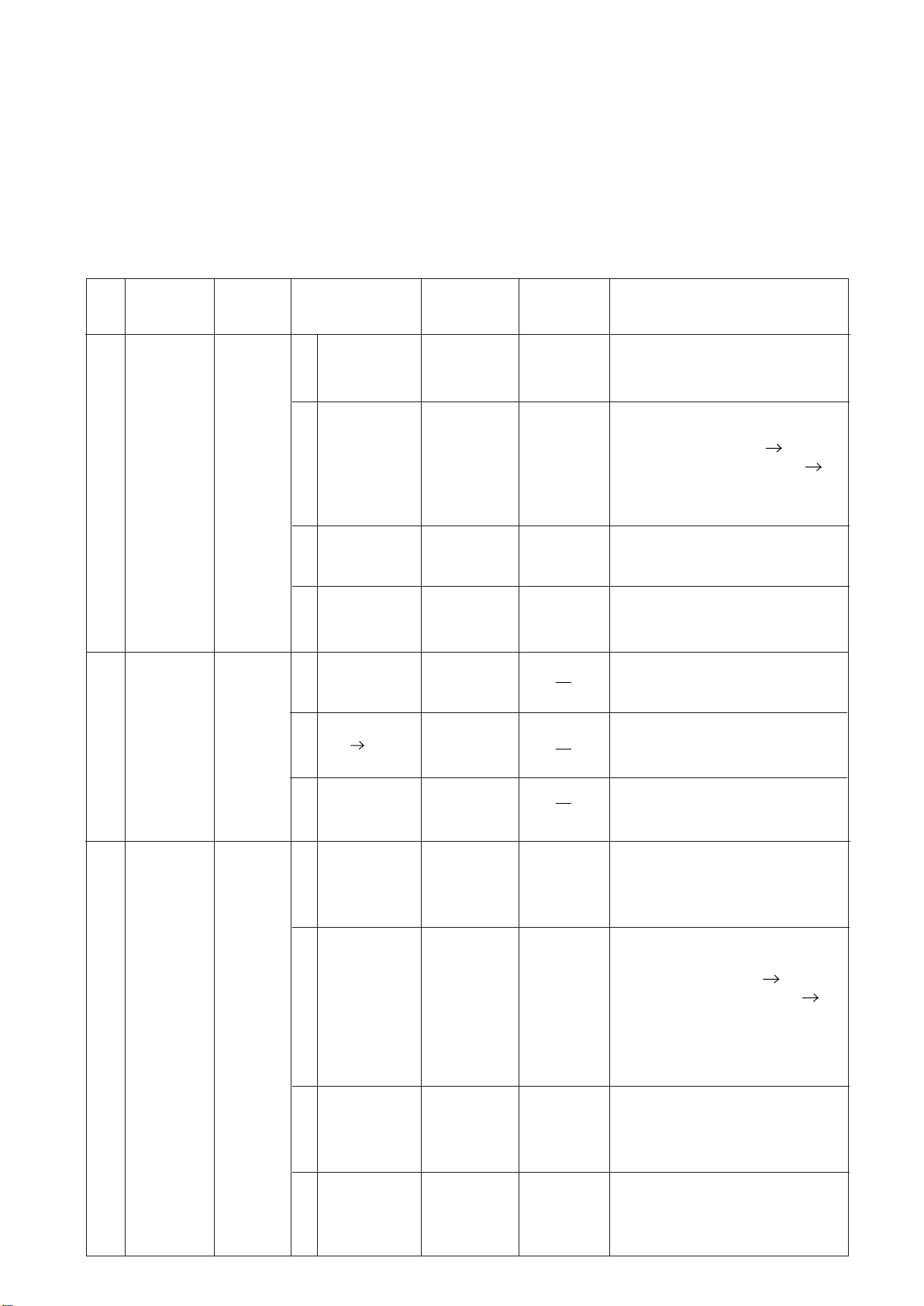
(4) Adjustment Procedures
Step Description
Signal Meter
Auto
1
Adjustment
(FM)
Connection
3
Figure
Signal Generator
87.5MHz,
(1)
(2)
(3)
(4)
26dBµ
(Mod. OFF)
87.5MHz,
26dBµ
(Mod. OFF)
87.5MHz,
21~23dBµ
(Mod. OFF)
87.5MHz,
26dBµ
(Mod. OFF)
Control
Dial
87.5MHz
87.5MHz
87.5MHz
87.5MHz
Test Point /
P.W.Board
Coordinates
TP002
(3-F)
TP501
(3-F)
TP002
(3-F)
TP501
(3-F)
TP002
(3-F)
TP501
(3-F)
TP002
(3-F)
TP501
(3-F)
Adjustment
Auto Adjustment:
After setting up of Signal Genarator,
short GND and TP501 (Pull-Down)
for 2~3 seconds.
Proceed same Auto Adjustment of step
(1) under step (2).
(SPEC) TP002 : 1.5±0.1V OK
(SPEC) TP002 : others 1.5±0.1V NG
NOTE : NG : Proceed same Auto
Adjustment of step (1)
under step (3).
Proceed same Auto Adjustment of step
(1) under step (3).
Proceed same Auto Adjustment of step
(1) under step (4).
CDA-9853R
Det Out-DC
OFFSET
2
Adjustment
(FM)
Signal Meter
Auto
3
Adjustment
(MW)
Figure
Figure 4
87.5MHz,
(1)
3
(2)
(3)
(1)
(2)
(3)
26dBµ
(Mod. OFF)
87.5MHz,
-20dB26 µ
(Mod. OFF)
87.5MHz,
-20dBµ
(Mod. OFF)
999kHz,
34dBµ
(Mod. OFF)
999kHz,
34dBµ
(Mod. OFF)
999kHz,
29~31dBµ
(Mod. OFF)
87.5MHz
87.5MHz
87.5MHz
999kHz
999kHz
999kHz
TP002
(3-F)
TP501
(3-F)
TP002
(3-F)
TP501
(3-F)
TP002
(3-F)
TP501
(3-F)
" DC OFFSET " displays after finishing
S-METER (FM) adjustment.
The SIGNAL GENERATOR output of
26dBu is lowered to -20dBu within
10 seconds.
When adjustment is finished,the
" DC OFFSET " display disappears.
Auto Adjustment:
After setting up of Signal Genarator,
short GND and TP501 (Pull-Down)
for 2~3 seconds.
Proceed same Auto Adjustment of step
(1) under step (2).
(SPEC) TP002 : 1.0±0.1V OK
(SPEC) TP002 : others 1.0±0.1V NG
:
NOTE NG : Proceed same Auto
Adjustment of step (1)
under step (3).
Proceed same Auto Adjustment of step
(1) under step (3).
(4)
999kHz,
µ
34dB
(Mod. OFF)
999kHz
TP002
(3-F)
TP501
(3-F)
Proceed same Auto Adjustment of step
(1) under step (4).
Page 10
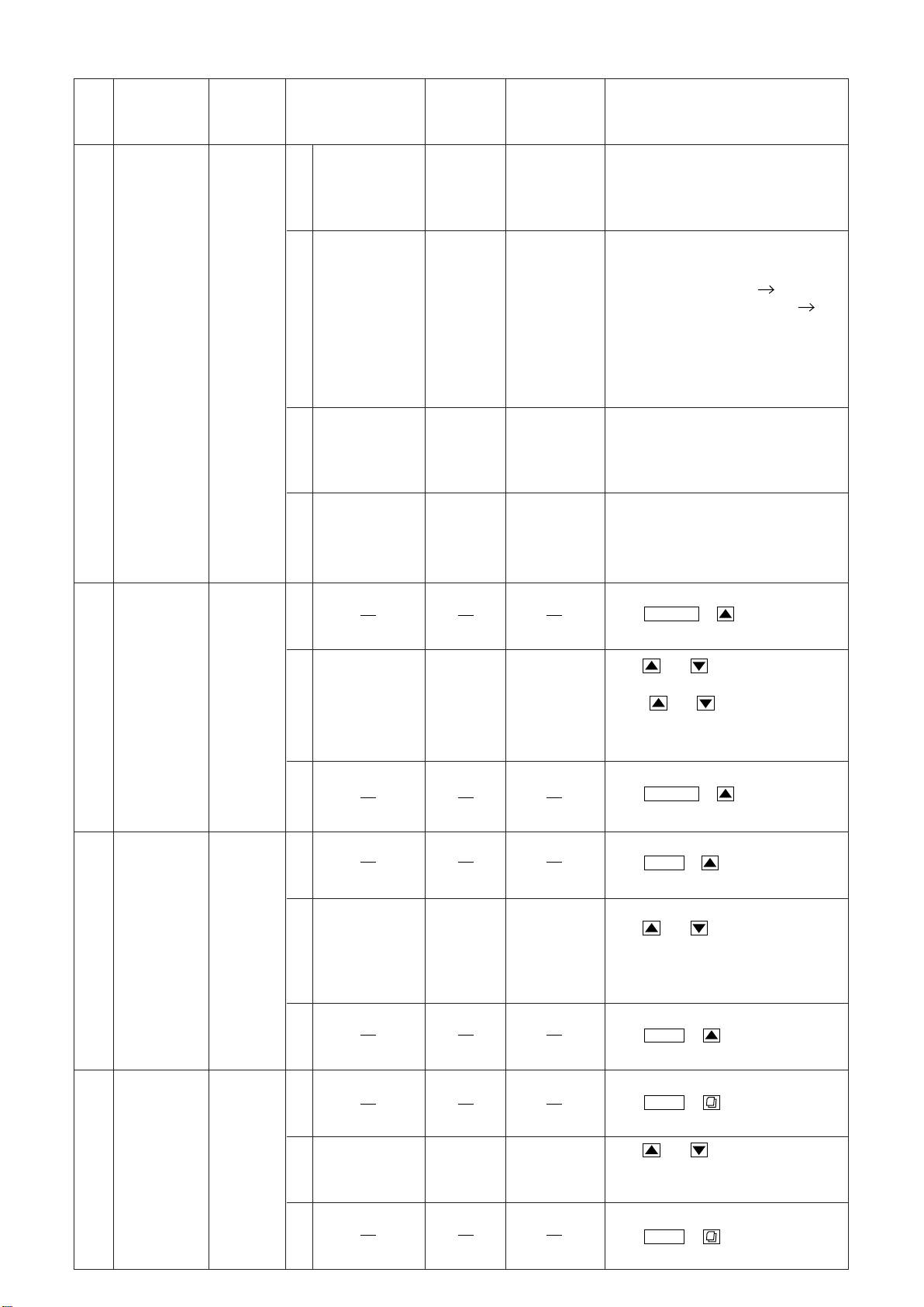
Step Description Connection Signal Generator Dial Control
TO CONTENTS
- 10 -
Test Point /
P.W.Board
Coordinates
CDA-9853R
Adjustment
Signal Meter
Auto
4
Adjustment
(LW)
Figure 4
(1)
(2)
(3)
(4)
(1)
216kHz,
34dBµ
(Mod. OFF)
216kHz,
34dBµ
(Mod. OFF)
216kHz,
29~31dBµ
(Mod. OFF)
216kHz,
34dBµ
(Mod. OFF)
216kHz
216kHz
216kHz
216kHz
TP002
(3-F)
TP501
(3-F)
TP002
(3-F)
TP501
(3-F)
TP002
(3-F)
TP501
(3-F)
TP002
(3-F)
TP501
(3-F)
Auto Adjustment :
After setting up of Signal Genarator,
short GND and TP501 (Pull-Down)
for 2~3 seconds.
Proceed same Auto Adjustment of step
(1) under step (2).
(SPEC) TP002 : 1.0±0.1V OK
(SPEC) TP002 : others 1.0±0.1V NG
NOTE : NG : Proceed same Auto
Adjustment of step (1)
under step (3).
Proceed same Auto Adjustment of step
(1) under step (3).
Proceed same Auto Adjustment of step
(1) under step (4).
Set up of Adjustment Mode :
Push KeyPOWER
at the same time.
+
FM ST
Separation
5
(Roll OFF)
Adjustment
Stereo Blend
6
Adjustment
(Lch)
Figure 5
Figure 5
98.1MHz, 72dBµ
(Mod. 400Hz,
(2)
Dev. 40kHz,
Stereo, 1kHz,
Lch only)
(3)
(1)
98.1MHz, 46dB
(Mod. 400Hz,
(2)
Dev. 40kHz,
Stereo, 1kHz,
Lch only)
(3)
(1)
µ
98.1MHz
98.1MHz
Audio Output
(RCA)
Audio Output
(RCA)
Push Key, andand
observe value of separation.
Select of maximum
separation.
(SPEC) : separation : more than 20dB.
Cancel Adjustment Mode :
Push
at the same time.
Set up of Adjustment Mode :
Push KeyBAND
at the same time.
Push
observe value of blend.
(SPEC) : Blend : 8±6dB.
Cancel Adjustment Mode :
Push
at the same time.
Set up of Adjustment Mode
Push
at the same time.
Keyand
+
KeyPOWER
+
Key, andand
+
KeyBAND
:
+
KeyBAND
7
Limitting
Adjustment
Figure 6
98.1MHz, 24dBµ
(2)
(Mod. 400Hz,
Dev. 40kHz)
(3)
98.1MHz
Audio Output
(RCA)
Push
observe value of limitting.
(SPEC) : Limitting : 3dB.
Cancel Adjustment Mode :
Push
at the same time.
Key, andand
+
KeyBAND
Page 11

Step Description Connection Signal Generator Dial Control
TO CONTENTS
- 11 -
Test Point /
P.W.Board
Coordinates
CDA-9853R
Adjustment
8
Noise Level
Adjustment
Figure 6
(1)
(2)
(3)
98.1MHz,
72 --> -20dBµ
(Mod. OFF)
98.1MHz
Audio Output
(RCA)
Set up of Adjustment Mode
Push
at the same time.
Rotary encoder is turned and noise level
is adjustment.
(SPEC) : Noise Level : 30 10dB.
Cancel Adjustment Mode :
Push
at the same time.
+
+
:
KeyBAND
±
KeyBAND
Page 12
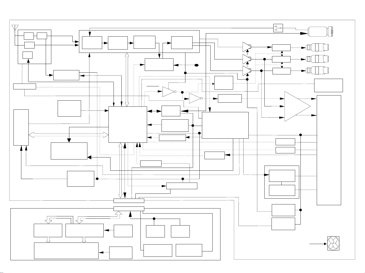
Block Diagram
TO CONTENTS
- 12 -
Tuner unit
RF IF
AM
PLL
RDS Decoder
TUNER+B
(MP3 CD MECH)
Tuner on
OEM
Steering
DP23S8DA
Remote
MOTOR-DRIVER
Selector
SWD+3.3V
CD
VDD
Vol.1
I²C BUS
Main CPU
Tre/Bass
A-Mute
Nose DET
E-VOL
DSP
AI-NET
8V DET SW
Vol.2
DSP+5V
I/F
RESET
Nose PWR SW
MUTE
DRIVER
Delay Circuit
Power cont
SYSTEM POWER IC
Batt-Det / VDD
PWR-ON / CD SERVO
TUNER ON / DSP+5V
MOTOR-DRIVER
ACC DET
MOTOR-DRIVE
CD-SERVO
Buffe
Buffer
Buffe
Buffer
Buffe
Buffer
PWR ON
Pre IN/OUT Selector
Slide SW
MUTE
MUTE
MUTE
Power IC
IN INT
DIMMER
PWR ANT
Rem SW
CDA-9853R
OEM SUB
DISPLAY
READY I/F
Front
Rear
BATT
IN-INT
DIMMER
ACC
P.ANT
O.REM
Ai-Net
DIN
Pre-OUT
Sub Woofer
Pre-OUT
Front
Pre-OUT
Rear
POWER CONNECTOR
LCD DRIVER
FRONT u-COM
LCD
DISPLAY
Key
Matrix
LCD+B
Rotary
Encoder
Nose
Lamp
Remote
Control
Nose
LED
AUDIO +B
LAMP +B
FAN Control
FAN
Page 13
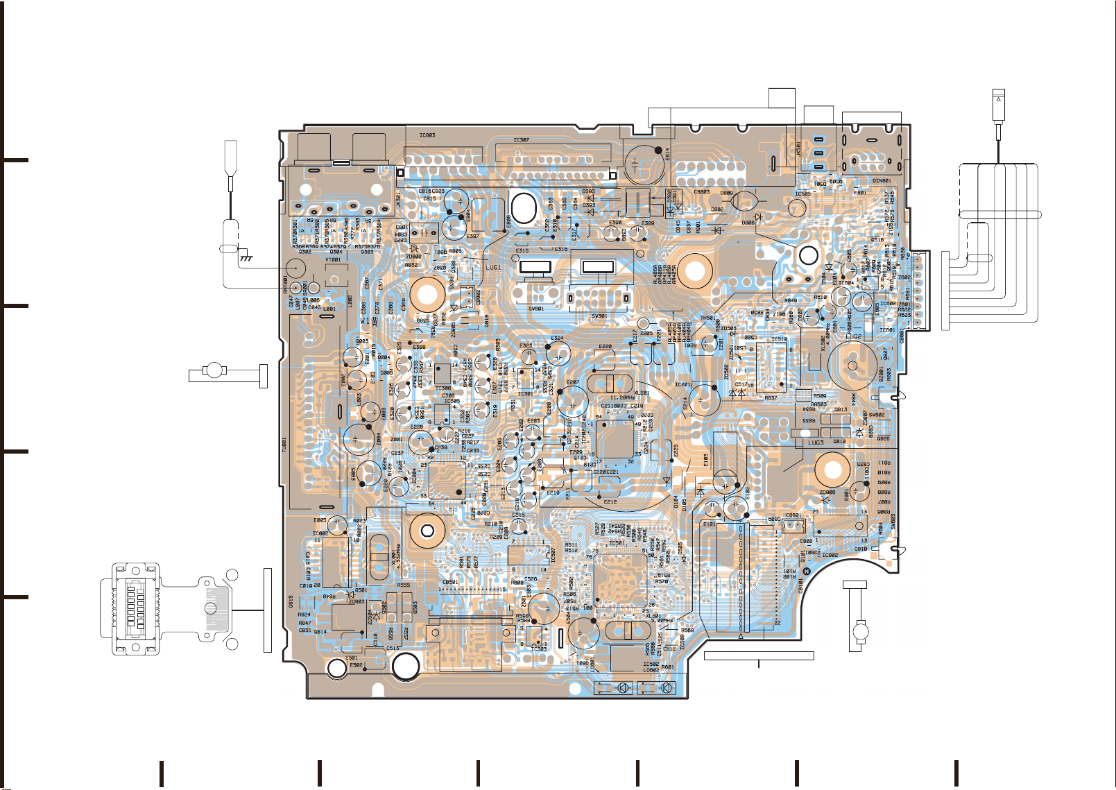
Parts Layout on P.W.Boards and Wiring Diagram(1/4)
TO CONTENTS
- 13 -
CDA-9853R
1
2
4
5
3
MOTOR,F2510CT-12UCV
(FAN MOTOR/12V-40mA)
CH501
ASSY,UNIZON CONN 93R
(Top Side View)
1
(CH401)
15
2
14
To FRONT P.W.Board
ANT001
ASSY,ANT CABLE 9851R
BLK
WHT
(ANT)
M802
RED BLK
M
A
SHIELD
1
15
To TUNER Chassis
2 1
To CB802
15 1
C047
To CB501
2
R381
6
R370
L007
Q815
R824
C831
C019
MAIN P.W.Board
(Component Side View)
1
IC803
3113
46
R015
C012
ZD504
E502
R384
R377
R376R375 R374
C371
C370
B
E
R220
XL001
1235
C510
5
Q004
Q005
R219
Q501
E
B
C513
2
Q805
C804
C825
R832
C369
C368
E388
E325
R347
E326
E320
Z001
E228
C237
Q201
E
B
E229
R555
EB
EB
Q503
Q502
R557
R556
C801
R831
B
E
C355
C337
C354
C816
C815
R826
Q389
R367
R366
8
31
Q302
R369 R368
SA001
ANT001
L006
C046
C045
20
1
TU001
C015
C016
1
5
32
R847
E811
R382
R371
L001
B
E
6
R385
644
R378
VT001
E005
R848
Q304
L002
IC002
ZD803
1
JK301
R386
R380
R379
E001
E002
L003
Q814
R383
R372
R023
E501
C366
E
Q003
B
E004
E805
R022
34
7
Q303
C367
E003
R827
ZD802
B
E
B
E
C827
R391
C305
C307
C239
C823
R825
Q801
Q387
R852
IC306
C306
IC305
E804
R803
R804
R835
C308
C240
IC204
E387
Q388
51
ZD805
R373
C349
C352
E227
R218
C227
R581
CB501
15
14
23
R388
CB802
12
Q818
EB
C357
R360
R363
R217
C236
C235
C225
R577
R575
E328
E327
E319
C233
C232
C231
C229
C228
E806
IC307
R305
C318 C315
R210
1
R330 R327
C210
R209
2
R331
E205
E204
E215
C208
L502
E323
E213
R598
R588
E315
IC301
E203
R600
Z501
E202
E206
E218
IC507
L503
1463
R337
R333
E503
IC503
CB502
C363
C362
E316
SW601
C325
C321
E208
E209
E219
C526
C365
E318
R506
R507
E324
C213 C212
R511
R512
C364
6
R502
R513
E317
E207
C214
E211
B
Q601
E
C242
C215
E504
24
25
D395
D393
E390 E389
712
1
E220
XL201
C211
C209
IC202
C219
C221
C220
E212
R528
R527
IC501
1
3
C389
R541
R542
XL501
D392
SW301
C218
R529
R530
IC502
Z205
E217
R500
R212
R546
E814
D391
C222
C224
R548
R566
R565
16
8
D809
C845
D802
R801
C837
E812
TH501
IC201
E214
VT120
E105
R508
E201
ZD502
Q816
C223
R629
R643
E221
R630
R644
R631
R645
R632
R646
R304
R633
R647
R201
1
3
E225
D105
E103
D104
E102
E101
R559
R547
R558
R560
D505
R561
R519
R570
R569
1
54
IC508
C525
3
C512
C511
R601
From DP-S MAIN P.W.Board (CB104)
LD602 LD601
9
C522
ZD503
L501
ZD501
C517
ZD804
To CB101
CB803
R850
R637
Q810
Q811
CB201
CB101
1
D806
CB
C834
IC510
B
E
102
Q817
C809
CB801
E104
R849
R635
3
2
R860
R636
21
R101
R102
R103
R104
R105
R107
C103
C802
15
Q101
122
IC505
5431
IC102
E602
XL502
RA503
R834
R833
ZD806
JK501
1
2
3
D501
R610
ZD801
B
Q509
E
E606
Z101
C518
D504
E604
E601
R509
EB
Q813
BE
Q812
IC802
C807
C808
To CB801
3641
DIN801
87
F801
R537
R545
R532
R536
Q515
R504 R503
R573
R572
3512
Q517
B
E
D502
Q516
D503
R614
R613
R607
R617
IC604
R609
R612
C604
IC602
1345
IC601
E
R616
Z601
5431
B
Q827
Q602
3
4
R619 R618
R620
61
Z602
R621
R622
R623
E603
E605
R606 R605
BZ801
R603
ZD807
C835
C811
E801
C828
Q826
3512
R811
R810
R809
R808
R807
R806
SW602
R844
R604
SW603
C810
CH801
ASSY,WIRE 2P9835
M801
MOTOR,LOAD FF-050SK
(NOSE MOTOR/7V-370mA)
BRN
21
WHT
M
ASSY,AMP LINK53A
ET601
SHIELD
PNK
SHIELD
(12C CLOCK)
91
To CB601
CB601
ORG
RED
(12C DATA)
BLK
YEL
(AMP DATA)
(AMP POWER GND)
WHT
(H/U GND)
BLK
GRN
(H/U CLOCK)
(H/U DATA)
A
Orange Color Pattern:Component Side Pattern
Blue Color Pattern:Foil Side Pattern
FGEDCB
Page 14
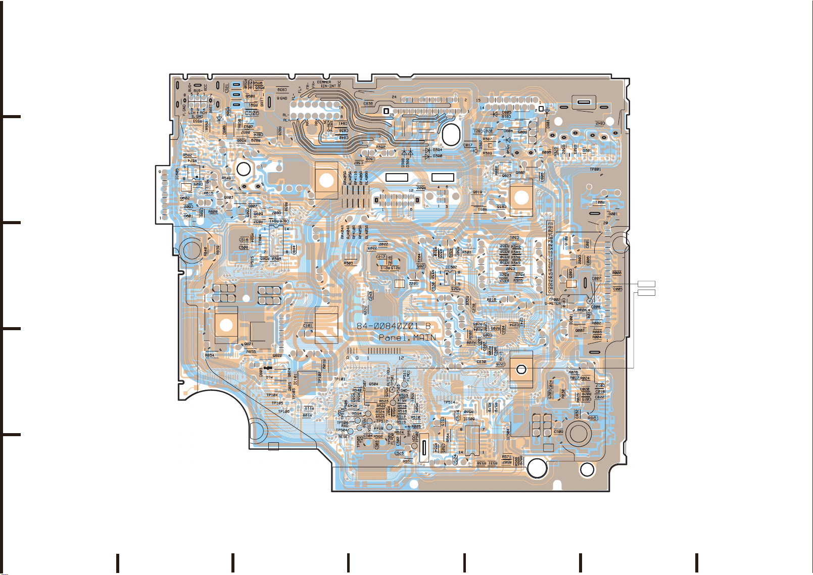
Parts Layout on P.W.Boards and Wiring Diagram(2/4)
TO CONTENTS
- 14 -
CDA-9853R
1
2
4
3
R534
R574
C602
R553
R533
R582
IC605
C605
D602
D601
Q514
C601
R552
IC506
R611
R840
C520
R615
R608
R854
R535
R550
R839
C521
R589
D808
R549
R590
C519
R591
R856
R857
R599
R829
R112
R114
2253
Q803
135
1
C603
R584
C516
C508
B
E
R595
E
B
C506
C507
C824
L101
Q807
R837
Q821
R855
Q508
R830
R596
C102
E
B
TP515
R585
2
Q822
135
D803
MAIN P.W.Board (Foil Side View)
Q102
D807
Q809
R841
R842
R116
IC804
253
1
2
135
C839
R828
C826
R586
C803
R845
Q824
Q825
C843
C105
R838
R862
TP104
TP105
C844
TP103
TP106
3
R111
R108
R113
C101
IC101
1
TP102
R109
TP101
C841
C838
C840
R843
C847
R563
R543
C387
R303
R562
TP504
C388
R221
R540
TP506
R594
TP508
R539
TP505
C836
Z203
C243
1
Q504
253
TP513
TP512
R544
C504
R520
R521
TP507
C503
R392
Z202
C217
R526
R522
R524
R525
R592
R523
R587
C216
R213R211
R583
TP509
D388
TP501
TP503
R514
TP510
C502
D389
R518
R516
R517
R515
R624
C523
TP511
R593
R501
R551
R602
C205
Z201
R505
D394
D390
Z204
R510
R005
TP502
R320
R332
C330
R554
R335
C515
C505
R329
IC302
R323
R564
TP514
R642
R307
C514
C524
R208
R576
R580
2
135
R314
R306
R324
R202
C822
C821
C817
Q819
R851
C238
R203
R204
IC509
R538
C202
C203
C201
R206
C207
C230
R578
R641
R640
R531
C805
C820
R387
D387
R389
R205
R579
R802
C833
R321
R357
R216
C206
C226
C846
C818
2153
R836
R362
R352
R350
R358
R215
R567
R390
Q823
C302
C204
Q806
C301
C234
R571
R805
R322
1
R568
D804
R349
R341
R339
R345
R365
C241
IC504
R628
D805
3
3512
Q802
Q808
D801
B
E
C806
C024
C025
D302
R325
R029
R016
C013
C010
R030
C509
D303
C003
1
IC001
3
B
Q002
E
C009
C002
R017
R008
R026
R027
R025
C832
C014
45
C026
R028
C023
C001
Q001
C006
R014
R024
C020
C842
D301
R001
C027
TP002
R002
R003
R004
C017
R861
TP001
C004
C007
C008
R007
C018
C022
C028
C030
C032
C036
D001
C029
R006
C031
C005
C033
C034
C035
TP002
TP501
5
A
Orange Color Pattern:Component Side Pattern
Blue Color Pattern:Foil Side Pattern
FGEDCB
Page 15

Parts Layout on P.W.Boards and Wiring Diagram(3/4)
TO CONTENTS
- 15 -
1
FRONT P.W.Board
(Component Side View)
LD445
R437
R441
R472
LD465
R463
LD464
Q410
R498
R4104
Q421
SW408
2
15
LD437
LD411
SW407
R450
3
R476
R477
SW412
LD426
LD415
R449
SW405
R464
R458
Q418
B
R4023
E
LD450
R433
C413
SW422
LD428
LD406
To CB406
SW427
CB406
LD442
81
LD429
LD433
LD407 LD405
LD404 LD403
SW404
LD416
C411
C412
R435
4
IC405
1
R479
LD418
LD446
23
LD438
LD417
SW415
R478
SW417
SW414
LCD401
LD457LD456
LD410 LD409
ASSY,SMK010001B ( ) (Top Side View)
2
SW406
LD466
SW410
SW411
LD444
SW409
LD463
R462
R474
LD408
LD412
LD471
R475
LD413
LD414
CDA-9853R
LD461 LD460
SW413
LD441
SW420SW418
LD425
B
4
5
3
Q414
B
Q405
E
B
Q406
E
R460
R436
E
R468
R4022
R4108
R4021
R469
R470
R430
R4110
B
Q409
R4114
R4113
C404
C405
C406
C407
C408
E
E
R4105
R459
C425
B
Q413
B
Q412
Q416
R4107
E
R461
E
B
R4112
R4111
R4106
B
Q420
R4109
R417
TH401
R418
R419
ZD408
C402
C410
C409
C403
IC402
R415
R414
R416
R413
R444
R412
C429
B
FRONT P.W.Board
(Foil Side View)
TP407
C421
R440
R439
R438
R410
R404
R486
C420
XL401
C428
C415
TP406
C414
TP405
IC401
RA404
R451
R454
R429
TP401
C423
R421
R423
C422
R467
R473
RA401
TP402
R457
R493
R483
R489
R492
TP403
R402
R424
R426
R485
R453
R497
R427
R456
D455
C431
TP404
R432
RA403
R482
C416
R411
D410
R466
R431
D454
R434
D467
R481
R4101
R495
D453
R491
D463
R487
R484
R480
E
B
D462
R494
Q419
D451
R490
D411
R442
R408
R406
CH401
R407
To CH401
1 8
To ASSY,UNIZON CONN 93R (CH501)
D413
R405
D408
159
R471
D407
R403
D406
RA402
Q417
35
R488
R428
R401
R447
12
C424
C417
IC403
C430
R445
R465
E
Q415
B
R455
R496
R452
R446
R448
R409
R4102R4103
ZD401
Q411
R425
R422
R420
R443
R499
Orange Color Pattern:Component Side Pattern
Blue Color Pattern:Foil Side Pattern
A
FGEDCB
Page 16

Parts Layout on P.W.Boards and Wiring Diagram(4/4)
TO CONTENTS
- 16 -
DP-S MAIN P.W.Board
1
The patterns should be short-circuited,
when the PICKUP is removed
from DP-S Mechanism.
2
3
(Foil Side View)
TP1
TP2
TP3
15 1
TP5
TP8
TP10
To CB101
TP12
TP14
TP169
TP4
TP7
TP9
TP11
TP13
TP15
R134
C301
R302
IC301
31
R314
C311
TP71
R133
C302
Q302
TP72
R301
54
R315
C125
C126
C127
C128
TP168
IC103
R304
5431
E804
R127
R128
R129
R130
TP77
IC302
C807
R802
R131
R132
E107
TP167
C303
CB101
TP144
R135
Q802
B
TP145
TP147
TP171
TP76
TP75
R140
R176
R137
TP170
R313
C306
C304
IC303
TP58
TP59
R102
R104
C102
R103
R101
Q801
C806
E
TP166
TP146
TP131
TP137
R141
C138
TP121
TP123
RA107RA106
TP79
TP80
TP81
R139
C137
R138
R136
TP165
R305
R306
C101
TP61
E106
EB
TP139
TP138
R152
TP125
TP82
R144
R143
TP108
TP164
Q301
B
C305
Q101
C145
TP70
TP100
R175
TP159
TP122
TP78
TP129
TP114
R142
C307
E
R311
C310
R309
C105
TP90
C139
Q102
TP130
R310
E102
R105
E
C103
B
TP60
C106
R106
TP68
R107
C107
R117
C122
TP67
TP69
C121
R124
C124
C123
C120
TP63
TP172
32
R126
R125
33 16
C134
C135
48
R147
R153
C133
C136
TP99
TP105
R151
R172
R149
IC104
R174
R159
R158
TP132
E
TP116
B
TP115
TP126
R307
IC304
R312
C143
TP174
C132
RA103
R167
TP163
R161
C309
R308
C308
C104
C144
IC101
E105
C118
R123
C119
CL101
R148
C142
R150
R160
TP104
L202
E202
C117
IC102
RA109
TP103
TP106
RA104
R164
C116
17
6449
RA105
D101
R169
C201
R109
TP62
C110
C111
R114
R122
R119
C115
R118
C114
1
C130
RA108
TP89
RA102
R173
R155
Q103
R108
R115
TP66
C113
TP176
TP161
C131
TP95
C140
R171
R170
TP158
L201
R156
E201
C108
R111R110
R113
TP64
TP65
R116
TP173
R120
TP96
L101
R154
C205
C202
TP175
R112
C109
C112
TP178
R121
TP177
R145
TP160
C129
TP92
TP93
TP94
TP156
R182
R181
R814
R206
L102
C206
R146
R184
R183
E108
E203
RA113
R203
R204
R201
TP97
R168
R157
L203
R813
RA112
C210
C213
C212
R205
IC201
C204
C220
R202
C203
XL201
R805
R208
TP113
R207
R808
C207
R815
TP34TP33TP32TP31TP30
TP35
TP28TP27TP26TP25TP24TP23TP22
To
C805
E803
C214
R209
TP155
R812
C208
d
R216
R211
E206
RA111
TP29
17
C219
17
R210
d
4513
C221
E205
R806
C209
RA110
E204
R810
C804
IC802
E802
L204
TP110
TP109
CB103
To CB103
C802
C803
31
R214
R212
C216C215
R213
C218
R215
3512
R803
Q803
TP17
TP16
TP18
TP19
TP20
TP21
71
4
71
d
To
54
C217
IC801
C801
R801
CB104
R166
E801
TP157
CB102
TP40
TP42
TP39
TP37
TP51
TP54
TP56
TP44
TP46
TP48
TP41
TP38
TP36
TP50
TP52
TP53
TP49
TP57
TP47
TP55
TP43
122
To CB104
To MAIN P.W.Board (CB101)
FPC,CONT P.W.Board
(Foil Side View)
CDA-9853R
5
A
DP-S Switch P.W.Board
(Foil Side View)
Orange Color Pattern:Component Side Pattern
Blue Color Pattern:Foil Side Pattern
FGEDCB
Page 17

SW601
TO CONTENTS
TO PARTS LIST
TO P. W. BOARD
- 17 -
SSAC120100
SW602
SW,DETCT SPVG2106-E6
SW603
SW,DETCT SPVG1107-E6
DTC114EKA
LD601
SML-010DT
LD602
SML-010DT
R601
430-1/4
Q601
R603
R604
22k
R526
TP501
R542
22k
R541
N.U.
R521
N.U.
10k
R602
47k
R508 12k
R501 1k
R502 N.U.
R505 10k
R506 1k
R507 10k
R510 4.7k
R513 91k
TH501 100k
R511 100
R512 100
R514 15k
R517 22k
R593 27k
R515 180k
R516 180k
R518 N.U.
R522 10k
R523 10k
47k
R520
R527 100
R528 100
IC501
D70F3263YGC
0
R592
XL501
R524 1k
R525 1k
C502
R583 470
R587 470
5.00MHz
4.7
12p
15p
C503
C504
R588 100
R598 100
R531 10k
R538 10k
22k
R500 100
R546 100
R548 100
R529 470
R530 470
1k
R543
R547 100
R559 100
R560 100
R561 100
R569 100
D505
MA2S728
R519 1k
R570 100
TP515
0
R635
R509
0
0
R637
N.U.
R636
TP514
R600
47k
R544
100k
R539
0
IC502
TA48M033F
E504 220/10
C523 0.1
TP502
R554 22k
C525
TP508
TP505
TP504
TP509
TP511
TP503
R558
560
R562 10k
R540 22k
R563
10k
TP506
TP507
C505
0.022
IC503
BR24L02F-W
0.01
TP510
R624
0
TP513
TP512
IC507
TC74HCT7007AFTP2-SE6
Q504
R551
FMC3A
10k
R564
220-1/4
3.9k
R565
22k
R566
IC508
BD5224G
C511 0.1
C512
0.047
E503
330/6.3
Z501
BK2125HM102
C515
0.022
1
C514
22
C526
R589
470k
R590
C506
22k
R595
R591
100-1/4
0.1
TC74HCT7007AFTP2-SE6
22k
R535
N.U.
R550
C521
N.U.
C520
N.U.
N.U.
Q509
DTC114EKA
2200p
N.U.
R536
R534 N.U.
R533 N.U.
D502
D503
R599
100p
C519
Q515
N.U.
N.U.
N.U.
Q514
N.U.
RA503
4.7k
XL502
4.00MHz
27p
C508
IC505
TC4S01F
C507
0.022
Q508
D501
2SB709A
MA152WK
2.2k
R596
3.3k
N.U.
R503
IC506
N.U.
N.U.
R504
C518
N.U.
E606
N.U.
R532
IC804
IC506
N.U.
C524
0.022.
R574
39-1/4
C516 27p
Q516
FMC3A
R552
39-1/4
R584
3.3k
R582
39-1/4
R585
1k
R594
JK501
JAC,CK-3.5-14
R553
39-1/4
IC510
MB88385CPF
4.7k
D504
1SS133
2.2k
1.5k
R537
R545
R549
10-1/4
Q517
DTA143EKA
R573 2.2k
R572 1.5k
ZD503
MAZS056
L501
C517
4.7k
ZD501
R586
0.35u
0.022
ZD502
RLZ7.5A
RLZ7.5A
IC509
TC74HCT7007AFTP2-SE6
R610 7.5k
E601 1/50
R608 4.3k
E602 10/16
C603 0.1
R609 1k
IC604
NJM2100V
10p
C604
R612 3.6k
3.6k
R614
R611
R617
E603
10/16
IC601
TC7SH08FU
R605 10k
R606 10k
IC602
TC7SH08FU
D601
0.1
C601
1PS226
0.1
C602
D602
R607 560
1PS226
R613
470-1/4
IC605
C605 0.1
BA8275F
R618 470-1/4
E604
R615
8.2k
1k
R616
8.2k
1k
10/16
E605
10/16
Z602
NFM21HC102R1H
Z601
NFM21HC102R1H
R619 4.7k
Q602
HN1K06FU
R622 1k
R623 1k
4.7k.
R620
4.3k
R621
CB601
53253-0910
Q501
FMC3A
Q502
2SD1994A
560-1/4
2SD1994A
R555
ZD504
HZS9C1L
ASSY,AMP LINK53J
R556
2.2-1/4
R557
2.2-1/4
Q503
C509 1
ET601-1
IC504
AN7705SP
E502 22/16
E501 22/16
C510 0.33
C513 0.1
R568
R567
10k-1/8
22k
R571 10k-1/8
CB501
IMSA9617S-15Y
CH501
ASSY,UNIZON CONN 93R
R628 2.7k
R578 1k-1/8
R579 1k-1/8
R575 1k-1/8
R577 1k-1/8
R581 330
R640
R641
N.U.
N.U.
N.U.
R576
R580
1k-1/8
N.U.
R642
C522
0.022
CB502
L502 N.U.
L503 N.U.
N.U.
Page 18

C203
TO CONTENTS
TO PARTS LIST
TO P. W. BOARD
- 18 -
C204
C206
C207
C201
4700p
C202
4700p
IC201
NJU7223DL1-33
R201
3.3-1/4
Z204
BK2125HM102
E201
E202
3.3/50
E203
3.3/50
E204
3.3/50
E205
3.3/50
E206
3.3/50
E213
3.3/50
4.7/35
E207
C205
220/10
E208
47/6.3
E209
47/6.3
47/6.3
E211
47/6.3
E212
47/6.3
Z205
0.45u
R202
1k
R203
1k
R204
1k
4700p
R205
4700p
1k
R206
1k
4700p
R208
4700p
1k
Z202
BK2125HM102
0.1
Z201
0.1
C242
0.1
C212
0.1
C213
0.1
C214
E219
0.1
C215
0.1
C219
BK2125HM102
E214
XL201
11.28MHz
R213
220/10
BK2125HM102
27p
C216
2.2k
C220
0.1
R211
Z203
1M
120
120
R209
R210
C208
C210
8200p
8200p
E218
E215
2.2/50
2.2/50
E217
47/6.3
C209
C211
27p
C217
0.1
0.1
E221
E220
47/6.3
47/6.3
IC202
TC94A48FG
C221
10
C243
100p
C218
1k
R221
0.1
C222 2.2
R212
C223 0.01
220
10
E225
C224
47/6.3
R215
24k
C225 1
C228 1
C229 1
C230 1
C231 1
C232 1
C233 1
C234 1
C235 0.015
3.3k
R217
360p
C227
220k
R218
C226 1
C236
0.1
R216
IC204
TDA7412
0.1
C237
C238 1000p
C239 0.68
2.2k
C240 N.U.
E227 10/16
C241
Q201
N.U.
0.068
R219
R220
470
330
E228
E229
22/16
100/10
CB201
N.U.
R303
0-1/4
R320
SW301
N.U.
C318 15p
R329
R330 24k
22k
R307
22k
IC302
C315 15p
R327 24k
IC301
NJM2060V
E323
E324
3.3/50
100/10
15p
24k
C321
R333
22k
R335
R337 24k
22k
C325 15p
BA4560F
C330
R331 1.1k
R324 1.1k
R323 1.1k
0.022
R332 1.1k
R306
0-1/4
R325
10/16
R326
10/16
E327
10/16
E328
10/16
E319
10/16
E320
10/16
R349
22k
75k
R341
R345
22k
36p
C337
R347
75k
R339
75k
36p
R350
C349
R358
22k
R352
R357
22k
75k
R321
75k
R322
R365
22k
24k
IC306
NJM2060V
24k
R360
75k
R362
22k
C352 36p
R363
IC305
BA4560F
R366 24k
C354 36p
C355 36p
R373
C357 36p
24k
3.3
C302
R314
24k
R367
3.3
N.U.
C301
C305
3.3
C306
24k
N.U.
C307
C308
3.3
C366
3.3
1k
R325
D301
MA152WA
C367
3.3
C368
3.3
D302
MA152WA
C369
3.3
C370
3.3
D303
MA152WA
C371
3.3
R370
220-1/8
Q302
XN0F256
62k
R368
62k
R369
R371
220-1/8
R372
220-1/8
Q303
XN0F256
62k
R375
62k
R376
R377
220-1/8
R378
220-1/8
62k
R374
62k
R379
Q304
XN0F256
R380
220-1/8
R385
100-1/8
R386
100-1/8
R381
100-1/8
R382
100-1/8
R383
100-1/8
R384
100-1/8
SLD-42-508G
JK301
RCA-NLT1989-0
C842
3900p
Page 19

C801 0.27
TO CONTENTS
TO PARTS LIST
TO P. W. BOARD
- 19 -
Q824
FMC3A
Q825
FMC3A
Q805 N.U.
N.U.
Q806
R826
N.U.
R827
N.U.
N.U.
D388 S1G-6904
D389 S1G-6904
D390 S1G-6904
D394 S1G-6904
IC307
TA8273H
D387
R387
0-1/4
1SS355
R388
N.U.
R389
100-1/4
Q387
DTC114EKA
10k
R390
Q388
FMC2A
E387
47/16
Q389
DTC124EKA
R391
390
E390
1/50
E388
0.22/50
E389 10/16
C387 1000p
C388 0.047
C389
0.22
D391 S1G-6904
D392 S1G-6904
D393 S1G-6904
D395 S1G-6904
D801
SIG-6904
Q823
FMC3A
R801
10k-1/4
D802 S1G-6904
Q801
DTC143EKA
C804
0.22
6.2k
R802
C805
N.U.
6.2k
R803
N.U.
R804
N.U.
C846
IC803
HA13165
Q802
FMC3A
R805
30k-1/4
C806
C815
0.1
E806
220/16
100p
C816
0.22
D804
S1G-6904
D805
S1G-6904
E804 470/10
E805 220/6.3
C817 0.47
C818 0.1
C820 0.1
C821 0.22
C822 N.U.
C823 0.1
N.U.
C843
R825
C802
D803
MA159
E315 0.68/50
E316 0.68/50
E317 0.68/50
E318 0.68/50
Q811 N.U.
R842
Q810
N.U.
N.U.
R845
Q808
C809
0.022
CB801
IC802
BA6219BFP-Y
0.022
ZD801
N.U.
C807
RD3.6MB2
C808 N.U.
R806 33-1/4
R807 33-1/4
R808 33-1/4
53253-0210
C810
0.022
E801
C811
47/16
R809 33-1/4
0.022
R810 33-1/4
R811 33-1/4
Q807
FMC2A
C844
1000p
Q803
FMC3A
D806
MA165-(QZ)
DTC124EKA
R829
6.8k-1/4
R828
3.3k-1/4
C824 0.1
ZD802
HZS6C3L
0.1
C825
N.U.
R831
N.U.
R830
R835
47k
R836
27k
R832
N.U.
Q812
R833
2SD1994A
2.2-1/4
Q813
2SD1994A
R834
2.2-1/4
R844
1.8k-1/4
1
C828
ZD807
HZS9A2L
Q826
FMC3A
R862 N.U.
N.U.
R847
2.2-1/4
N.U.
N.U.
E812
ZD804
Q814
2SD1760
470
ZD803
C832 0.1
R861 100k
HZS12A3LRX
C803 N.U.
N.U.
C847
C831 0.022
E811 N.U.
R824 100k
R848
R843
C362 0.22
C363 0.22
C364 0.22
C365 0.22
N.U.
Q816 N.U.
Q815
FMC3A
10k
R392
4A
F801
D808
S1G-6904
R856
270-1/4
R857
270-1/4
C845
0.01
R854
2.2-1/4
DIN801
CON,TCP9389-11
C836
E814
0.022
3300/16
Q821
2SD1760
1
C835
Q822 FMC3A
R855
390-1/4
ZD806
HZS12B1LRX
CH801
ASSY,WIRE 2P 9835
MOTOR, LOAD FF-050SK
M801
Q809
DTA143EKA
15k
R837
30k
R841
2.2-1/4
HZS12A1LRX
R852
53253-0210
0.22
C833
1
C827
CB802
M802
MOTOR,F2510CT-12UCV
D809
C839
DSA3A4
0.01
C837 0.01
C840 0.01
CB803
C841 0.01
C838 0.01
ASSY, W277A001
Q818
2SD874A
R840
1k-1/4
R839
10k-1/8
BZ801
D807
MA152WK
R838
10k-1/4
C826
0.022
XY13-5H
Q827
DTC114EKA
10k
R849
Q817
DTC124EKA
18k
R860
R850
10k-1/4
1
C834
Q819
FMC3A
R851
560-1/4
ZD805
Page 20

CB101
TO CONTENTS
TO PARTS LIST
TO P. W. BOARD
- 20 -
SFW22R-1STE1
TP001
ANT001
ASSY, ANT CABLE9851A
TU001
MB4R002Z(SHA)T.UNIT
C027
N.U.
C033 N.U.
R003 1k
R004 1k
R101 22k
L006
L007
C028 N.U.
C035
N.U.
TP101
TP102
R103 N.U.
R102 22k
0.027u
0.039u
C029
N.U.
C031
N.U.
C034 N.U.
C036
N.U.
TP103
CB102
C105 N.U.
VT120
R029
N.U.
E105
N.U.
C103
N.U.
C020
0.1
R022 270
R023 270
R024 1k
R025 1k
N.U.
4.7k
R030
N.U.
C026
27p
C025
R111
0
TP104
TP105
TP106
Q101
R104 N.U.
FMC3A
N.U.
R105
SA001
DSP-201M-C04F
VT001
4.7u
L001
52mH
15u
L002
62p
C045
C047
10
R001
18p
39p
C046
C030
N.U.
C004 N.U.
D001
1PS226
N.U.
E001
C001
C009
0.022
R005
47k
TP002
N.U.
C032
C006 0.047
C007 10p
C005 0.01
C008 0.01
22/16
R006
1k
L003 4.7u
10-1/4
R007 N.U.
R002
C002
0.022
C010 0.1
R008 100k
N.U.
E002
C012
22/16
IC001
TC7S66F
N.U.
C003
E003
C013
0.022
R108
0
N.U.
R107
22/16
R015
R016
R109
3.3-1/4
E101
4.7/35
Q003
2SB709A
3.3k
1.5k-1/4
Q005
DTC114EKA
NJU7223DL1-33
Q004
DTA123YKA
IC101
D105
S1G-6904
E103
D104
S1G-6904
E102
100/10
E004
220/10
R017 N.U.
C101
0.022
N.U.
470/10
R113
Z001
BK2125HM102
C015
330p
C019
2200p
C014 N.U.
IC102
Q102
N.U.
R112
N.U.
C017 100p
C018 0.022
Z101
N.U.
N.U.
N.U.
R114
L101
N.U.
N.U.
N.U.
C102
E104
IC002
E005
SAA6588T
47/6.3.
C016
560p
XL001
4.33MHz
470k
R028
C023
2.2
C022
2200p
27p
C024
N.U.
R116
N.U.
10k
10k
R026
R027
Q001
R014
22k
Q002
N.U.
DTC114EKA
Page 21

IC402
TO CONTENTS
TO PARTS LIST
TO P. W. BOARD
- 21 -
S1D15206F11A200
LCD401
LCD,NTD-22729AAHU-CU
SW422
SKRPACE010
N.U.
C413
100
R411
R401 12k
R403 1k
R471 1k
R405 1k
R406 1k
R407 2.2k
R408 1k
CH401
RA401
RA402
1k
R473 100
R489 100
RA403 100
R457 100
R4023 1k
R453 1k
R485 1k
1k
TP401
TP405
TP407
TP406
R497
22k
TP402
TP403
TP404
IC403
NJU6060V
R418
R454
22k
R462 240
R463 270
R463 330
R465 220k
0.1
0.1
C402
C403
ZD408
0.1
R416
N.U.
N.U.
R466 22k
R467 22k
N.U.
1M
1.2M
R417
TH401 100k
R419
R423
0.1
0.1
0.1
C404
C405
820k
0.1
C423
100
C422 0.1
R444 100
R4113 1k
R438 100
C430
0.1
R4114 1k
R439 100
R440 100
0.1
C421
Q417
FMC3A
Q421
FMC3A
LD471
0.1
C406
C407
C408
100
RA404
IC401
200
R488
91
R498
R446
0.1
N.U.
Q411
R460
N.U.
Q410
N.U.
N.U.
R445
Q414
C409 0.1
C410 10
N.U.
N.U.
C415
R449
R450
10k
R426 1k
R424 1k
R402 1k
10k
R415
R414
XL401
20.00MHz
R432
10k
R456
10k
R427
10k
1k
R413 1k
R412 1k
D406 1PS226
D407 1PS226
D408 1PS226
D410 1PS226
D411 1PS226
SW420
SKRPACE010
560
R499
10k
R428
LD463LD464LD465
LD406
LD466
2SD1328
330
R4105
2SD1328
150
R4108
Q409
DTC114EKA
D463
1PS226
R480 22k
R481 22k
R482 22k
R483 22k
R484 22k
Q412
Q420
750
R442
R496
LD410
LD409
LD414
Q419
DTC114EKA
R4107 1k
R4106 1k
R487 22k
CB406
C428 10p
C429 12p
C420 0.1
R404 22k
R486 22k
R410 100
SW404
SKRPACE010
SW409
SKRPACE010
SW415
SKRPACE010
R474 2.7k
C414
0.1
R433 2.7k R437 3.9k
SW405
SKRPACE010
SW410
SKRPACE010
R478 2.7k
SW417
SKRPACE010
R434 1k
R435 1k
SW406
SKRPACE010
R475 3.9k
SW411
SKRPACE010
R479
3.9k
C431
0.1
R441 8.2k R472 27k
SW407
SKRPACE010
SKRPACE010
R476
8.2k
SW412
SKRPACE010
SW427
R477 27k
SKRPACE010
SW408
SW413
C411
N.U.
C412
N.U.
N.U.
R4102
N.U.
R4103
N.U.
R4104
R431 1k
R490 1k
R491 1k
R492 1k
R493 1k
R494 1k
R495 1k
22k
R4101
R409
LD407 LD405LD403LD404
D467
SW414
SKRPACE010
220
R420
LD408
LD426
R436
D451
1PS226
430
1k
1PS226
LD411
LD412
D453
R422
430
Q405
2SD1328
1PS226
SW418
N.U.
430
680
R425
R429
LD425
LD417 LD416
LD418
Q418
DTC114EKA
D454
D455
D462
1PS226
1PS226
1PS226
IC405
RS-671
D413
1PS226
C416 1
680
750
560
560
1.2k
R421
R443
LD444
LD413
LD415
1k
R430
1.2k
R447
R448
LD437
LD429
LD438LD446
LD445
Q406
2SD1328
1.2k
R451
R452
LD428LD433
LD441
LD450 LD442
R41121kR4111
Q415
2SD874A
Q416
2SD1328
Q413
2SD1328
1k
R455
ZD401
470-1/4
MA3082-H
C417
0.1
2.2
R458
C424 0.022
C425 0.022
R461
R459
110-1/4
110-1/4
LD456
NSCW505CT
LD457
NSCW505CT
LD460
NSCW505CT
LD461
NSCW505CT
51-1/4
R4109
24-1/4
R4110
Page 22

HD101
TO CONTENTS
TO PARTS LIST
TO P. W. BOARD
- 22 -
PICKUP, EP21A67T
SW1 SPVG21
SW2 SPVG11
M101
ASSY, MOTOR-WORM
CB101
IMSA-9616S-15Y900
IMSA-9616S-07Y900
SW105
SPVG210
M102
ASSY, MOTOR SLED 2B0
SW3 SPVG21
C101
TP15
TP14
TP13
TP12
TP11
TP10
TP9
0.01
R208 100
R209 100
C208
TP97
RA111
47k
C807
0.022
Q802
UN5212
L202
4.7u
R808 470
R207
47k
C207 1
TP155
0.1
TP109
TP110
R815
47k
TP95
TP96
R812 47k
Q801
UNR212X
R206
47k
10
C145
C105 0.047
TP67
TP68 TP69
R307
10k
R308
10k
0.1
R309 47k
R310 3.3k
R311
1k
TP169 TP168
R136
10k
R133
27k
E107
10k
R139
6.8k
TP60
TP61
R109
R110
15k
4.7k
C108
R111
C110
R113
4.7k
100
0.1
TP64
C111
0.1
R115
R114
100
39k
TP65 TP66 TP173
R117
100
C309
0.033
IC304
NJM2100V
C310
2.2
10/16
R184 100
R183 220
R182 220
R181 220
TP156
0.1
C129
C130
C131
0.1
0.1
RA108
470
RA109
470
TP99
TP100
0.1
C133
C132 1
100k
R147
C136
R153
220
E108
0.1
C142
R160 2.2k
R161 2.2k
0.01
C140
22/6.3
R170 N.U.
R168 100
R171 47k
R173 100k
RB161M-20
R157 100
R154 100
TP158
RA104
R164
TP89
TP90
L101
BK1608HM102-T
0.1
47k
RA105
D101
R155
N.U.
47k
47k
R156
R169
47k
47k
C135
0.1
0.1
47k
RA102
4.7k
RA103
4.7k
TP103
TP104
TP106
TP108
R802
TP113
TP114
TP115
TP116
E804
330k
47/5.5
TP176
C124
C125
0.047
R152
TP126
C113
0.1
E105
22/6.3
2.2M
R118
C115
0.015
E106 10/16
C116 0.01
C117 2700p
C118 0.01
TP174
C119
0.1
R124 1k
C120 0.033
C121
0.01
R125 3.3k
R126 3.3k
C126
1200p
100
TP159
TP121
TP123
TP81
TP80
TP79
TP125
TP178
TP177
R120
R121
47k
5.6k
47p
C114
R119 470k
R122
15k
R123
10k
TP172
TP71
R127
TP72
1k
R128
TP144 TP145
1k
R129
R131 100
TP146 TP147
1k
R130
R132 100
1k
0.01
0.01
C127
C128
2200p
C139
47k
R175
TMP91CP27UG-X
TP129
TP175
C109
R112
3.9k
3p
47p
TP62
TP63
C112
R116
1k
4700p
TP70
TP170
TP171
C123
0.047
C122 0.01
RA106 47k
RA107 47k
TP76
TP77
TP78
TP75
R176
47k
R145 100
R146 100
TP160
TP161
TP92
TP93
TP94
IC102
TC94A14FA
C134
TP105
2.2
47k
680
R172
R151
1M
R167
CL101
TP122
TP137
TP138
TP139
IC104
TP130
TP131
TP132
47k
R174
27.00MHz
47k
R149
R148
R158 100
R159 100
100
R150
10
C104
0.047
N.U.
R107
C107 N.U.
47k
0.01
C305
R141
C144
R108
N.U.
IC101
TA2157FN
C308
0.1
C307
TC7WH123FU
R312
47k
R135
10k
R134
10k
R137
C137
N.U.
R138
10k
91k
Q103
N.U.
R101 91k
R103 47k
C102
0.022
R104 47k
R102 91k
TP58
TP59
Q301
UN5212
220k
R314
R315
0.1
C311
R304
TP164 TP165
C302
0.022
IC301
TC7S66FU
0
TC7SH08FU
N.U.
R142
C143 10
1
R105
Q101
2SB1132
IC302
IC103
BA5985FM
39k
E102
47/5.5
C103
0.022
RA110
R106 39k
C106
22p
22k
R313
C304
470p
R305
0
R306
IC303
C303
0.022
C306
0.022
C138
180p
TP167
R140
240
R143
47k
R144
120k
22k
TP166
TP1
TP2
TP3
TP4
TP5
TP7
TP8
Q302
N.U.
470p
C301
R302
47k
330k
R301
TP16
TP17
TP18
TP19
TP20
TP22
TP23
TP24
TP25
TP26
TP27
TP28
TP21
Q102
UN5112
TP29
TP30
TP31
TP32
TP33
TP34
TP35
CB103
M103
ASSY, MTR SPINDOL 2B0
SW4 SPVG21
E201
L201
47/5.5
4.7u
E202
R805
100k
47/5.5
R211
C806
68k
C202
12p
C203
10p
C209
1
0.022
TP163
R803
R166 100
L102 BK1608HM102-T
XL201 16.93MHz
R202
47
C220
18p
C204
0.1
R810
C210
0.1
E203
47/5.5
47k
470
L203
Q803
XN1A312
C201
0.022
0.33
C205
1M
R201
100k
R806
C219
0.1
4.7u
R203
E205
C206 220p
220
R205
IC201
TC94A20F-008
22/6.3
R210
560k
C221
22
E204
22/6.3
E803
R204
330
E802
4.7/35
330
E206
22/6.3
47u
L204
C803
4.7/35
C805
0.022
150
R216
R212
120
R213
120
IC801 RN5RZ25BA
0.022
IC802 RN5RZ25BA
R814
47k
RA113
C215
4700p
C216
4700p
0.1
C212
47k
47k
RA112
R214
62
C217
R215
C218
62
0.1
C802
0.1
C804
47k
R813
0.1
C213
0.1
C214
TP36
TP37
0.01
0.01
470k
R801
E801
C801
47/5.5
0.022
TP38
TP39
TP40
TP41
TP42
IMSA-9616S-22Y900
CB102
N.U.
CB104
TP46
TP47
TP48
TP49
TP50
TP51
TP52
TP53
TP54
TP55
TP56
TP57
TP44
TP157
TP43
Page 23

CDA-9853R
TO CONTENTS
TO SCHEMATIC
- 23 -
Terminal Voltage of IC/TR
IC001
No. Voltage Note
1 3.16
2 3.11
3 0
4 4.96
5 4.96
IC002
No. Voltage Note No. Voltage Note No. Voltage Note
1 PS 8 5.04 15 0
2 PS 9 PS 16 2.53
3 0 10 PS 17 2.53
4 2.55 11 NC 18 2.53
5 2.17 12 0 19 2.53
6 0 13 2.53 20 2.53
7 5.05 14 5.05
IC101 IC201
No. Voltage Note No. Voltage Note
1 3.31 1 3.3
2 6.57 2 7.49
3 0 3 0
IC202
No. Voltage Note No. Voltage Note No. Voltage Note
1 1.58 23 0 45 0
2 3.28 24 0 46 0
3 3.28 25 0 47 0
4 1.63 26 0 48 3.28
5 0 27 0 49 0
6 1.63 28 NC 50 3.28
7 3.28 29 NC 51 3.28/0 RESET OFF/ON
8 1.63 30 NC 52 3.28
9 0 31 NC 53 0
10 1.63 32 NC 54 0
11 0 33 NC 55 0
12 1.63 34 NC 56 0
13 3.28 35 NC 57 1.63
14 1.64 36 NC 58 1.63
15 0 37 0 59 3.28
16 1.63 38 3.28 60 1.63
17 3.28 39 0 61 1.63
18 3.28 40 0 62 0
19 0 41 0 63 0
20 0 42 PS 64 1.5
21 0 43 PS
22 0 44 NC
Page 24

CDA-9853R
TO CONTENTS
TO SCHEMATIC
- 24 -
IC204
No. Voltage Note No. Voltage Note No. Voltage Note
1 NC 16 4.6 31 4.24
2 NC 17 NC 32 4.24
3 4.24 18 3.55 33 4.24
4 4.24 19 0 34 4.24
5 4.24 20 PS 35 4.24
6 4.24 21 PS 36 4.24
7 4.24 22 8.5 37 4.24
8 4.24 23 NC 38 4.24
9 4.24 24 NC 39 4.24
10 4.24 25 4.24 40 4.24
11 4.24 26 4.24 41 NC
12 4.24 27 4.24 42 NC
13 4.24 28 4.24 43 NC
14 3.7 29 4.24 44 NC
15 PS 30 4.24
IC301
No. Voltage Note No. Voltage Note No. Voltage Note
1 4.26 6 4.26 11 0
2 4.26 7 4.26 12 4.26
3 4.26 8 4.26 13 4.26
4 8.55 9 4.26 14 4.26
5 4.26 10 4.26
IC302 IC305
No. Voltage Note No. Voltage Note
1 4.26 1 4.26
2 4.26 2 4.26
3 4.26 3 4.26
4 0 4 0
5 PS 5 4.26
6 PS 6 4.26
7 PS 7 4.26
8 8.56 8 8.55
IC306
No. Voltage Note No. Voltage Note No. Voltage Note
1 4.26 6 4.26 11 0
2 4.26 7 4.26 12 4.26
3 4.26 8 4.26 13 4.26
4 8.55 9 4.26 14 4.26
5 4.26 10 4.26
Page 25

CDA-9853R
TO CONTENTS
TO SCHEMATIC
- 25 -
IC307
No. Voltage Note No. Voltage Note No. Voltage Note
1 0 10 7.9 19 7.62
2 0 11 1.72 20 14.3
3 7.62 12 1.6 21 7.62
4 4.85 13 0 22 0
5 7.62 14 1.63 23 7.62
6 14.3 15 1.47 24 0
7 7.62 16 1.33 25 3.59
8 0 17 7.62
9 7.62 18 0
IC401
No. Voltage Note No. Voltage Note No. Voltage Note
1 PS 35 1.39 69 PS
2 NC 36 1.44 70 5.02
3 PS 37 0.02 71 5.02
4 PS 38 5.02 72 0.02
5 PS 39 NC 73 5.02
6 5.02 40 NC 74 NC
7 0.02 41 NC 75 5.01/0.03 SLIDER OFF/ON
8 4.91/0 AMB LED ON 42 NC 76 5.01/0.03 SLIDER OFF/ON
9 4.92/0 GRN LED ON 43 NC 77 5.01/0.03 SLIDER OFF/ON
10 NC 44 4.98/0/0 DIMMER 1/2/3 78 5.01/0.03 SLIDER OFF/ON
11 NC 45 0/4.87/0 DIMMER 1/2/3 79 5.01/0.03 SLIDER OFF/ON
12 NC 46 NC 80 5.01/0.03 SLIDER OFF/ON
13 NC 47 NC 81 5.01/0.03 SLIDER OFF/ON
14 NC 48 NC
15 NC 49 NC
16 NC 50 NC
17 NC 51 NC
18 0.02 52 NC 84 0/1.08/2.00 KEY ON
19 NC 53 NC 85 NC
20 NC 54 NC 86 5
21 NC 55 5.02 87 NC
22 NC 56 0.02 88 PS
23 NC 57 NC 89 NC
24 NC 58 NC 90 5
25 NC 59 NC 91 5
26 NC 60 NC 92 NC
27 NC 61 NC 93 5
28 NC 62 NC 94 NC
29 NC 63 NC 95 NC
30 NC 64 NC 96 PS
31 4.87 65 NC 97 PS
32 0.02 66 PS 98 PS
33 0.55 67 PS 99 PS
34 3.23 68 PS 100 PS
82
83
0/1.07/1.99/
3.00/4.03
0/1.08/2.01/
3.00/4.04
KEY ON
KEY ON
Page 26

CDA-9853R
TO CONTENTS
TO SCHEMATIC
- 26 -
IC402
No. Voltage Note No. Voltage Note No. Voltage Note
1 3.43 44 PS 87 PS
2 1.82 45 PS 88 PS
3 0.23 46 PS 89 PS
4 -1.37 47 PS 90 PS
5 -2.96 48 NC 91 PS
6 2.06 49 PS 92 PS
7 5.02 50 PS 93 PS
8 -9.78 51 PS 94 PS
9 -7.34 52 PS 95 PS
10 2.52 53 PS 96 PS
11 -2.34 54 PS 97 PS
12 2.52 55 PS 98 PS
13 0.02 56 PS 99 PS
14 5.02 57 PS 100 PS
15 0.02 58 PS 101 PS
16 5.02 59 PS 102 PS
17 0.02 60 PS 103 PS
18 0.02 61 PS 104 PS
19 0.34 62 PS 105 PS
20 0.02 63 PS 106 PS
21 5 64 PS 107 PS
22 NC 65 PS 108 PS
23 NC 66 PS 109 PS
24 NC 67 PS 110 PS
25 NC 68 PS 111 PS
26 NC 69 PS 112 PS
27 NC 70 PS 113 PS
28 NC 71 PS 114 PS
29 NC 72 PS 115 PS
30 PS 73 PS 116 PS
31 PS 74 PS 117 PS
32 PS 75 PS 118 PS
33 PS 76 PS 119 PS
34 PS 77 PS 120 PS
35 PS 78 PS 121 PS
36 PS 79 PS 122 PS
37 PS 80 PS 123 PS
38 PS 81 PS 124 PS
39 PS 82 PS 125 PS
40 PS 83 PS 126 PS
41 PS 84 PS 127 PS
42 PS 85 PS 128 PS
43 PS 86 PS
IC403
No. Voltage Note No. Voltage Note No. Voltage Note
1 5.02 6 1.9
2 PS 7 0
3 PS
4 PS
5 PS
8
0.08/2.79/
2.72/2.92
BLUE/GRN/
AMB/RED
9
10
3.04/0.09/
2.63/3.18
3.55/3.47/
0.27/3.72
BLUE/GRN/
AMB/RED
BLUE/GRN/
AMB/RED
Page 27

CDA-9853R
TO CONTENTS
TO SCHEMATIC
- 27 -
IC405
No. Voltage Note
1 4.86
2 0
3 0
4 4.62
IC501
No. Voltage Note No. Voltage Note No. Voltage Note
1 3.33 35 3.33 69 0
2 0 36 4.95 70 3.33
3 PS 37 3.33 CD 71 NC
4 PS 38 0/3.33 TUNER/CD 72 3.33/0 NOSE CLOSE/OPEN
5 3.33 39 PS 73 3.33
6 3.33 40 PS 74 0/3.27 CD
7 3.33 41 PS 75 0/3.33 2WAY/3WAY
8 0 42 PS 76 0
9 3.33 43 PS 77 0/3.33 NOSE CLOSE/OPEN
10 2.55 44 PS 78 3.33
11 0 45 0/3.33 BUZZER OFF/ON 79 3.33
12 1.17 46 PS 80 0/3.33 FAN OFF/ON
13 1.21 47 PS 81 0/3.33 CD/TUNER
14 3.33/0 RESET OFF/ON 48 PS 82 3.33
15 NC 49 3.33 83 3.33
16 NC 50 PS 84 0/3.33 IF MUTE OFF/ON
17 3.33 51 PS 85 0/3.33 RDS CONT OFF/ON
18 4.94 52 PS 86 0/3.33 BW CONT OFF/ON
19 4.91 53 PS 87 0/3.33 DOOR LED OFF/ON
20 0/3.27 TUNER/CD 54 PS 88 0/3.33 MOTOR OFF/ON
21 PS 55 PS 89 0/3.33 BL-LED OFF/ON
22 PS 56 PS 90 2.9
23 PS 57 PS 91 0/3.33 ADJCH OFF/ON
24 PS 58 PS 92 0/3.00 FM/AM
25 PS 59 3.33 93 2.88 HI-TEMP
26 PS 60 3.33 94 0/3.33 DISC IN
27 3.33/PS 61 0/3.17 DIMMER ON/OFF 95 NC
28 3.33 62 3.33/0 POW IC ON/OFF 96 PS
29 4.94/0 REMOCON OFF/ON 63 3.33 97 1.76
30 3.33 64 3.33/0 FM/AM 98 2.5
31 4.9 65 0/3.33 A MUTE ON/OFF 99 3.13
32 3.33 66 3.33/0 INT ON/OFF 100 1.64
33 0 67 3.33
34 3.33 68 NC
IC502 IC503
No. Voltage Note No. Voltage Note
1 4.96 1 0
2 3.34 2 0
3 0 3 4.95
4 0
5 PS
6 PS
7 0
8 4.95
Page 28

CDA-9853R
TO CONTENTS
TO SCHEMATIC
- 28 -
IC504 IC505
No. Voltage Note No. Voltage Note
1 8.68 1 PS
2 0 2 PS
3 4.95 3 0
4 PS
5 4.95
IC507
No. Voltage Note No. Voltage Note No. Voltage Note
1 3.33/0 POW IC ON /OFF 6 0 11 PS
2 4.9/0 7 0 12 PS
3 3.33 8 PS 13 PS
4 4.9 9 PS 14 4.9
5 0 10 PS
IC508
No. Voltage Note No. Voltage Note
1 0/3.33 RESET ON/OFF 4 NC
2 1.27/3.33 RESET ON/OFF 5 1.77/0 RESET ON/OFF
3 0
IC509
No. Voltage Note No. Voltage Note No. Voltage Note
1 PS 6 0 11 0
2 PS 7 0 12 4.9/0 DF ON/OFF
3 PS 8 0 13 3.33/0 DF ON/OFF
4 PS 9 0 14 4.9
5 0 10 0
IC510
No. Voltage Note No. Voltage Note No. Voltage Note
1 PS 7 PS 13 PS
2 PS 8 0 14 0
3 PS 9 4.9 15 4.9
4 PS 10 0 16 4.9
5 1.83 11 4.9
6 2.2 12 PS
IC601 IC602
No. Voltage Note No. Voltage Note
1 4.95 1 4.95
2 PS 2 PS
3 0 3 0
4 PS 4 PS
5 4.95 5 4.95
Page 29

CDA-9853R
TO CONTENTS
TO SCHEMATIC
- 29 -
IC604 IC605
No. Voltage Note No. Voltage Note
1 PS 1 0
2 PS 2 PS
3 PS 3 PS
4 0 4 0
5 PS 5 0
6 4.95 6 PS
7 PS 7 PS
8 4.95 8 4.95
IC802
No. Voltage Note No. Voltage Note No. Voltage Note
1 NC 10 12.43 19 0
2 0/5.97 ANGLE action 11 12.43 20 0
3 NC 12 NC 21 0
4 0/4.4 ANGLE action 13 0 22 NC
5 NC 14 NC 23 NC
6 0/4.4 ANGLE action 15 0/4.7 ANGLE action 24 0/4.7 ANGLE action
7 0 16 NC 25 NC
8 0/4.4 ANGLE action 17 NC
9 NC 18 NC
IC803
No. Voltage Note No. Voltage Note No. Voltage Note
1 NC 6 5.15 11 2.44
2 13.7 7 4.9 12 7.06/0 CD/TUNER
3 4.43 8 14.4 13 1.33
4 5.7 9 1.8 14 10.14
5 5.04 10 8.56 15 0
IC804
No. Voltage Note No. Voltage Note No. Voltage Note
1 0 6 PS 11 0
2 0 7 0 12 PS
3 PS 8 PS 13 PS
4 PS 9 PS 14 4.9
5 PS 10 0
Page 30

CDA-9853R
TO CONTENTS
TO SCHEMATIC
- 30 -
Ref. B C E
Q002 3.28 0 0
Q003 7.78 8.48 8.55
Q004 0 8.49 8.55
Q005 3.29/0 0/8.54 0/0
Q201 3.28 0 0
Q387 0/3.28 4.38/0 0/0
Q389 4.35/0 0/4.16 0/0
Q405 0.74 0 0
Q406 0.74 0 0
Q409 0 6.73 0
0 6.73 6.73
Q412
Q413
Q415 8.65 11.58 8
Q416 DIMMER 2
Q418 4.61 0.05 0
Q419 4.58 0.1 0
Q420
Q502 9.35 14.27 8.75
Q503 9.35 14.27 8.75
Q508 4.38 4.96 5
Q509 2.54 0 0
Q517 0/3.3 3.25/0 3.3/3.3
Q601 3.2 0 0
Q801 3.29/0 0/4.79 0/0
Q808 1.2/0 0.37/1.75 0/0
Q809 2.92/4.9 4.66/0 4.67/4.9
Q812 8.11 13.93 7.49
Q813 8.11 13.93 7.49
Q814 12.72 14.56 12.1
Q817 9.68/0 0/3.17 0/0
Q818 12/0 14.4/14.4 11.39/0
Q821 12.9 14.1 12.4
Q827 0.4/0 11.42/13.99 0/0 BUZZER ON/OFF
4.81 6.74 6.74
0 6.74 6.74
0 0.64 0
0.75 0 0
0 0.39 0
1.36 0.64 0.63
0 0.94 0
0 1.16 0.39
4.84 6.73 6.73
0 6.74 6.74
0 6.74 6.74
Over Voltage Detect ON/OFF
Note
AM
FM
FM/AM
MUTE ON/OFF
MUTE ON/OFF
DIMMER 1
DIMMER 2
DIMMER 3
DIMMER 1
DIMMER 2
DIMMER 3
DIMMER 1
DIMMER 3
DIMMER 1
DIMMER 2
DIMMER 3
RESET ON/OFF
TUNER/CD
IN INT ON/OFF
DIMMER ON/OFF
FAN ON/OFF
Page 31

CDA-9853R
TO CONTENTS
TO SCHEMATIC
- 31 -
Ref. 1 2 3 4 5
Q101 0 3.29 3.3 3.27 0
Q388 0/14.4 14.4/0 14.4/14.4 4.38/0 0/0
4.96 5.02 4.84 0 0
Q417
Q421
Q501 0 14.4 14.4 3.29 0
Q504 0 3.31 3.31 3.31 0
Q516 0/4.87 4.84/1.95 4.93/4.87 3.27/0 0/0
Q802 5.03/0 0/4.88 5.04/0 0.3/1.75 0/0
Q803 0 4.69 4.74 4.7 0
Q807 0 4.7 4.72 4.94 0
Q815 0 14.4 14.4 3.29 0
Q819 0/13.96 13.87/0 13.89/13.99 3.28/0 0/0
Q822 0 14.06 14.09 3.03 0
Q823 0 4.88 4.89 3.3 0
Q824 0 12.35 12.35 3.15 0
Q825 0 12.28 12.42 3.03 0
Q826 0 14.11 14.15 3.2 0
4.12 5.02 0 4.96 0
4.27 5.02 0 5 0
4.47 4.96 0 0 4.95
4.05 4.12 4.81 0 0
3.92 4.27 0 4.26 0
Note
MUTE ON/OFF
DIMMER 1
DIMMER 2
DIMMER 3
DIMMER 1
DIMMER 2
DIMMER 3
RESET ON/OFF
Over Voltage Detect ON/OFF
FAN ON/OFF
Ref. 1 2 3 4 5 6
Q302
Q303
Q304
Q602
[Measuring Conditions]
1. Power Supply Voltage : DC14.4V
2. Measuring Meter : Digital Multimeter
3. Measuring Point Reference : Between GND
4. Measuring Condition : See each data
0/0 0/0 0/0 6.53/0 0/0 6.53/0
MUTE ON/OFF
0/0 0/0 0/0 6.53/0 0/0 6.53/0
MUTE ON/OFF
0/0 0/0 0/0 6.53/0 0/0 6.53/0
MUTE ON/OFF
4.44 4.95 4.52 0 0 0
OEM SUB-DISPLAY
It measures in normal temperature.
Page 32

CDA-9853R
(CD Deck Mechanism)
TO CONTENTS
TO SCHEMATIC
- 32 -
IC101
CD-DA PLAY MP3 PLAY CD-DA PLAY MP3 PLAY
1 3.32V 3.28V 13 3.30V 3.03V
2 - - 14 1.64V 1.66V
3 - - 15 1.62V 1.66V
4 1.66V 1.68V 16 1.62V 1.66V
5 1.70V 1.68V 17 2.62V 2.26V
6 0.26V 0.24V 18 1.68V 1.66V
7 2.54V 2.52V 19 1.36V 1.34V
8 2.04V 2.02V 20 0.30V 0.64V
9 1.70V 1.72V 21 2.48V 2.36V
10 1.64V 1.64V 22 1.32V 1.12V
11 1.60V 1.64V 23 0.08V 1.70V
12 2.54V 2.02V 24 0.14V 0.08V
IC102
CD-DA PLAY MP3 PLAY CD-DA PLAY MP3 PLAY
1 1.56V 1.66V 33 1.68V 1.62V
2 1.72V 1.68V 34 1.68V 1.62V
3 0.09V 0.10V-2.34V H/L 35 1.68V 1.64V
4 1.72V 1.66V 36 0.20V-1.20V H/L 0.38V-1.24V H/L
5 0.08V 0.10V-3.28V H/L 37 1.68V-2.56V H/L 1.68V-2.54V H/L
6 3.24V 3.24V 38 2.04V 2.08V
7 0.08V 0.10V 39 3.28V 3.22V
8 0.08V-3.24V H/L 0.08V-3.24V H/L 40 1.60V 1.16V-1.66V H/L
9 0.00V 0.00V 41 1.76V 1.66V-2.10V H/L
10 3.28V 3.24V 42 0.08V 0.10V
11 0.09V 0.10V 43 3.28V 3.24V
12 0.00V 0.00V 44 0.08V 0.10V
13 3.28V 0.10V-3.24V H/L 45 0.08V 0.10V
14 3.28V 3.24V 46 1.68V 1.66V
15 3.28V 3.24V 47 1.68V 1.66V
16 1.68V 1.68V 48 3.28V 3.22V
17 1.64V 1.60V 49 0.10V 0.10V
18 1.64V 1.66V 50 1.64V 1.66V
19 1.68V 1.66V 51 3.28V 3.22V
20 1.68V 1.66V 52 1.68V 1.64V
21 1.12V 1.10V 53 1.68V 1.66V
22 0.08V 0.10V 54 0.08V 0.10V
23 1.64V 1.66V 55 3.28V 0.10V-3.22V H/L
24 1.72V 1.68V 56 0.80V 0.10V
25 3.28V 3.22V 57 0.08V-3.28V H/L 0.10V-3.22V H/L
26 1.68V 1.66V 58 0.08V-3.28V H/L 0.10V-3.22V H/L
27 1.68V 1.68V 59 0.08V-3.28V H/L 0.10V-3.22V H/L
28 2.60V 2.34V 60 0.08V-3.28V H/L 0.10V-3.22V H/L
29 1.68V 1.64V 61 0.08V-3.28V H/L 0.10V-3.22V H/L
30 2.52V 2.00V 62 0.08V-3.28V H/L 0.10V-3.22V H/L
31 1.64V 1.58V 63 3.28V 3.24V
32 1.68V 1.64V 64 3.28V 3.24V
Page 33

CDA-9853R
TO CONTENTS
TO SCHEMATIC
- 33 -
IC103
CD-DA PLAY MP3 PLAY CD-DA PLAY MP3 PLAY
1 0.11V 0.10V 15 3.56V 3.50V
2 1.68V 1.66V 16 3.24V 3.24V
3 1.64V 1.66V 17 3.36V 3.35V
4 1.68V 1.66V 18 3.44V 3.44V
5 1.68V 1.66V 19 0.11V 0.10V
6 1.68V 1.66V 20 1.68V 1.64V
7 1.52V 1.52V 21 3.32V 3.30V
8 7.00V 7.00V 22 1.68V 1.62V
9 0.11V 0.10V 23 1.68V 1.64V
10 0.11V 0.10V 24 1.68V 1.64V
11 3.80V 3.80V 25 1.68V 1.64V
12 2.96V 3.00V 26 1.68V 1.64V
13 3.28V 3.26V 27 1.68V 1.64V
14 3.56V 3.50V 28 0.11V 0.10V
IC104
CD-DA PLAY MP3 PLAY CD-DA PLAY MP3 PLAY
1 0.10V 0.10V 33 0.10V-3.26V H/L 0.12V-3.12V H/L
2 0.10V 0.10V 34 3.24V 3.22V
3 0.10V 0.10V 35 0.10V 0.08V-3.18V H/L
4 0.10V 0.10V 36 0.10V 0.10V
5 0.10V 0.10V 37 0.10V 0.10V
6 0.10V 0.10V 38 0.08V 0.10V
7 0.34V-3.30V H/L 0.36V-3.28V H/L 39 3.30V 3.28V
8 0.10V 0.06V-3.28V H/L 40 3.30V 3.28V
9 0.34V-3.30V H/L 0.28V-3.28V H/L 41 0.10V 0.10V
10 0.08V 0.10V 42 0.10V 0.10V
11 0.24V-3.30V H/L 0.30V-3.30V H/L 43 3.30V 3.30V
12 0.28V-3.30V H/L 0.30V-3.30V H/L 44 0.08V 0.08V
13 0.08V 0.10V 45 0.08V 0.08V
14 3.22V 3.20V 46 0.08V 0.08V
15 3.22V 3.20V 47 0.08V 0.08V
16 0.08V 0.08V 48 0.08V 0.08V
17 - - 49 3.30V 3.28V
18 3.32V 1.68V 50 0.10V 0.10V
19 1.64V 3.30V 51 0.10V 0.08V
20 0.10V 0.00V 52 3.30V 3.30V
21 1.62V 3.02V 53 0.10V 0.14V
22 3.30V 3.28V 54 3.30V 3.30V
23 3.30V 3.28V 55 3.30V 3.30V
24 0.10V 0.10V 56 0.08V 0.08V
25 0.10V 0.10V 57 3.30V 0.28V-3.30V H/L
26 0.10V 0.10V 58 3.30V 0.28V-3.30V H/L
27 0.00V 0.00V 59 3.30V 3.30V
28 0.34V-3.28V H/L 0.38V-3.22V H/L 60 3.30V 3.30V
29 0.10V-3.26V H/L 0.12V-3.24V H/L 61 0.10V 0.08V
30 0.10V-3.26V H/L 0.12V-3.12V H/L 62 0.10V 0.08V
31 0.10V-3.26V H/L 0.12V-3.12V H/L 63 0.10V 0.08V
32 0.10V-3.26V H/L 0.12V-3.12V H/L 64 3.30V 3.30V
Page 34

CDA-9853R
TO CONTENTS
TO SCHEMATIC
- 34 -
IC201
CD-DA PLAY MP3 PLAY CD-DA PLAY MP3 PLAY
1 3.30V 3.28V 33 0.13V 0.10V
2 3.30V 3.28V 34 0.10V 0.10V
3 0.10V 0.10V 35 3.30V 3.28V
4 0.10V 0.10V 36 0.10V 0.10V
5 3.30V 0.42V-3.28V H/L 37 0.12V 0.10V
6 3.30V 0.40V-3.30V H/L 38 0.12V 0.10V
7 3.30V 3.28V 39 0.10V 0.10V-3.30V H/L
8 3.30V 3.28V 40 0.10V 0.10V
9 0.10V 0.10V 41 0.10V 0.10V
10 0.10V 0.10V 42 2.52V 2.50V
11 0.10V 0.10V 43 0.10V 0.10V
12 0.10V 0.10V-3.30V H/L 44 0.10V 0.10V
13 1.68V 0.00V-3.30V H/L 45 0.10V 0.10V
14 1.64V 0.08V-3.26V H/L 46 0.10V 0.10V
15 0.10V 0.10V 47 0.10V 0.10V
16 0.10V 0.10V 48 0.10V 0.10V
17 0.10V 0.10V 49 0.10V 0.10V
18 2.56V 2.54V 50 0.10V 0.10V
19 0.12V 0.10V 51 0.10V 0.10V
20 0.10V 0.10V 52 2.56V 2.52V
21 0.10V 0.10V 53 0.10V 0.10V
22 1.34V 1.32V 54 2.56V 2.52V
23 1.34V 1.32V 55 0.10V 0.10V
24 2.58V 2.58V 56 0.10V 0.10V
25 2.58V 2.58V 57 1.40V 1.42V
26 1.34V 1.36V 58 1.40V 1.42V
27 1.32V 1.36V 59 2.56V 2.56V
28 0.10V 0.10V 60 1.66V 1.66V
29 0.10V 0.10V 61 2.56V 2.60V
30 1.88V 0.00V-3.30V H/L 62 1.16V 1.20V
31 0.10V 0.10V 63 1.28V 1.20V
32 0.13V 0.10V 64 0.10V 0.10V
IC301
CD-DA PLAY MP3 PLAY
1 1.54V 1.54V
2 1.56V 1.56V
3 0.00V 0.00V
4 0.00V 0.00V PULSE : 2.76V (when disc scratch is detected)
5 3.17V 3.17V
IC302
CD-DA PLAY MP3 PLAY
1 0.00V 0.00V PULSE : 3.18V (when disc scratch is detected)
2 0.00V 0.00V PULSE : 2.95V (when disc scratch is detected)
3 0.00V 0.00V
4 0.00V 0.00V PULSE : 2.76V (when disc scratch is detected)
5 3.17V 3.17V
Page 35

CDA-9853R
TO CONTENTS
TO SCHEMATIC
- 35 -
IC303
CD-DA PLAY MP3 PLAY
1 0.00V 0.00V
2 0.00V 0.00V PULSE : 3.17V (when disc scratch is detected)
3 3.17V 3.17V
4 0.00V 0.00V
5 0.00V 0.00V
6 0.00V 0.00V
7 3.17V 3.17V
8 3.17V 3.17V
IC304
CD-DA PLAY MP3 PLAY
1 1.65V 1.65V
2 1.60V 1.60V
3 1.59V 1.59V
4 0.00V 0.00V
5 1.56V 1.56V
6 1.56V 1.56V
7 1.56V 1.56V
8 3.17V 3.17V
PULSE : 3.17V (when disc scratch is detected)
IC801 IC802
CD-DA PLAY MP3 PLAY CD-DA PLAY MP3 PLAY
1 0.10V 0.10V 1 0.10V 0.10V
2 3.30V 3.30V 2 3.30V 3.30V
3 2.56V 2.56V 3 2.56V 2.56V
4 0.00V 0.00V 4 0.00V 0.00V
5 3.30V 3.30V 5 3.30V 3.30V
Page 36

CDA-9853R
TO CONTENTS
TO SCHEMATIC
- 36 -
Q101 Q102
CD-DA PLAY MP3 PLAY CD-DA PLAY MP3 PLAY
B 2.54V 2.56V B 3.20V 3.22V
C 2.24V 2.26V C 1.66V 1.66V
E 3.20V 3.18V E 3.24V 3.22V
Q301
CD-DA PLAY MP3 PLAY
B 0.00V 0.00V
C 0.00V 0.00V
E 3.17V 3.17V
Q801 Q802
CD-DA PLAY MP3 PLAY CD-DA PLAY MP3 PLAY
B 0.16V 0.20V B 3.30V 3.30V
C 3.22V 3.24V C 0.16V 0.18V
E 3.22V 3.32V E 0.16V 0.12V
PULSE : 3.17V (when disc scratch is detected)
Q803
CD-DA PLAY MP3 PLAY
1 0.10V 0.10V
2 3.30V 3.28V
3 3.30V 3.28V
4 5.08V 5.06V
5 0.10V 0.10V
[Measuring Conditions]
1.Power Supply Voltage : DC12.2V
2.Measuring Meter : Digital Multimeter / Oscilloscope
3.Measuring Point Reference : Between GND
4.Measuring Condition
: (1) It measures in normal temperature with JIG.
(power supply voltage 12V)
(2) Two kinds are measured.
at playing CD-DA (TCD-782) and MP3 (SCD-5100)
(3) It measures in both sides of Analog and Digital.
Page 37

Description of IC Terminal
D70F3263YGC :
IC501
No. Symbol I/O Terminal Description
TO CONTENTS
TO SCHEMATIC
- 37 -
1 AVref1 - AVref power supply input terminal. (connect to VDD)
2 AVss - GND connect terminal for A/D Converter.
3 DSP CLK O DSP CLOCK output terminal.
4 DSP DATA I/O DSP DATA output terminal.
5 AVref2 - AVref power supply input terminal. (connect to VDD)
6 MOTOR FOR O Swing Mech FOR control terminal.
7 MOTOR REV O Swing Mech REV control terminal.
8 FLMD0 - FLMD0 input terminal.
9 VDD - VDD connect terminal.
10 REGC - Capacitor connect terminal. (4.7uF connect)
11 Vss - GND connect terminal.
12 MAIN XIN I
13 MAIN XOUT O
14 RESET I System Reset input terminal.
15 NC(GND) - GND connect terminal.
16 NC - No connect terminal.
17 NMI(PULL-UP) - Pull-up connect terminal.
18 BATT DET I BATT ON detection signal input terminal.
19 ACC DET I ACC ON detection signal input terminal.
20 CD F IN I FRAME data input terminal from CD Mech.
21 AiBUS IRQ I AI-NET BUS IRQ signal input terminal.
22 EVOL DATA O E-VOL and EEPROM DATA output terminal.
23 EVOL CLK O E-VOL and EEPROM CLK signal output terminal.
24 TUNER CLK O TUNER CLK output terminal.
25 AiBUS OUT O AI-NET BUS signal output terminal.
26 AiBUS IN I AI-NET BUS signal input terminal.
27 AiBUS SCLK O AI-NET BUS SCLK signal output terminal.
28 AiBUS RS O AI-NET BUS R/S signal output terminal.
29 REMOCON I Remote control signal input terminal.
30 AiBUS R/W O AI-NET BUS R/W signal output terminal.
31 AiBUS IRQ O AI-NET BUS IRQ signal output terminal.
32 AiBUS RST O AI-NET BUS RESET signal output terminal.
33 EVss - GND connect terminal.
34 EVDD - VDD connect terminal.
35 RDSMON TX O Command output terminal to RDS monitor.
36 RDSMON RX I Status input terminal from RDS monitor.
37 CD RST O RESET signal output terminal to CD Mech.
38 CD STBY O STBY signal output terminal to CD Mech.
39 TUNER DATA I/O TUNER DATA input / output terminal.
40 CD SFSY I CD TEXT DATA input terminal.
41 CD FOUT O FRAME signal output terminal to CD Mech.
42 CD SBSY O CD TEXT DATA output terminal.
43 CD TXD O Data output terminal to CD Mech.
44 CD RXD I Data input terminal from CD Mech.
45 BUZZER O Buzzer signal output terminal.
46 RDS CLK O RDS CLK output terminal.
47 RDS DATA I/O RDS DATA input / output terminal.
Crystal connect terminal for main system clock OSC.
CDA-9853R
Page 38

No. Symbol I/O Terminal Description
TO CONTENTS
TO SCHEMATIC
- 38 -
48 F-START O Front u-COM communication start output terminal.
49 F-RESET O Front u-COM RESET signal output terminal.
50 AMP DATA IN I AMP LINK DATA input terminal.
51 AMP DATA OUT O AMP LINK DATA output terminal.
52 AMP CLK O AMP LINK CLOCK output terminal.
53 F-IN I Data signal input terminal from Front u-COM.
54 F-OUT O Data signal output terminal to Front u-COM.
55 F-CLK I Clock signal input terminal from Front u-COM.
56 CD QDATAF I CD QDATA input terminal.
57 OEM SUB DATA O OEM SUB DISPLAY DATA output terminal.
58 OEM SUB CLK O OEM SUB DISPLAY CLK output terminal.
59 NOSE POWER O NOSE POWER control output terminal.
60 AUTO ADJ I TUNER auto adjustment input terminal.
61 IN DIMMER I DIMMER signal input terminal.
62 PWR IC ON O POWER IC control output terminal.
63 O-REM O OUT-REM signal output terminal.
64 FM/AM O TUNER power supply control signal output terminal. (Hi : FM, Lo : AM)
65 A.MUTE O A-MUTE output terminal.
66 ININT I IN INT input terminal.
67 DSP RESET O DSP RESET output terminal.
68 ARIA1(NC) - No connect terminal.
69 BVSS - GND connect terminal.
70 BVDD - VDD connect terminal.
71 NC - No connect terminal.
72 LIMIT SW1 I Swing Mech SW1 input terminal.
73 VDD PULLUP O Pull-up resistor power supply control output terminal.
74 ZERO-DET I ZERO DET signal input terminal.
75 2WAY/3WAY I 2WAY / 3WAY switching input terminal.
76 FLMD1(NC) - No connect terminal.
77 LIMIT SW2 I Swing Mech SW2 input terminal.
78 V-CONT(NC)
79 P-ANT(NC)
80 FAN CONT O FAN CONT output terminal.
81 CONT2
82 CONT1
83 P-CONT O POWER CONTROL output terminal.
84 IF MUTE O IF MUTE output terminal.
85 RDS CONT O RDS control output terminal.
86 BW CONT(NC) - No connect terminal.
87 DOOR LED O DOOR LED control terminal.
88 MOTOR ON O MOTOR power supply control terminal.
89 BL-LED O Backlight LED power supply control terminal.
90 DAVN I DAVN input terminal.
91 ADJCH DET I ADJCH detection input terminal.
92 AM SD I TUNER Seek Stop signal input terminal.
93 HI-TEMP I CD HI-TEMP signal input terminal.
94 DISC IN I CD DISC-IN detection signal input terminal.
95 VHH CONT(NC) - No connect terminal.
- No connect terminal.
O Power supply IC control terminal.
CDA-9853R
Page 39

No. Symbol I/O Terminal Description
D70F3033BGC :
IC401
TO CONTENTS
TO SCHEMATIC
- 39 -
96 MP I Multi-Path signal input terminal.
97 AFC I AFC signal input terminal.
98 SSTOP I SEEK STOP input terminal.
99 S/M I TUNER S/M level input terminal.
100 NOSE DET I NOSE installation detect terminal.
No. Symbol I/O Terminal Description
1 ENCODER-1 I ENCODER input terminal.
2 NC - No connect terminal.
3 FRONT-SI I Serial data input terminal from Main u-COM.
4 FRONT-SO O Serial data output terminal to Main u-COM.
5 FRONT-CLK O Communication synchronous clock output terminal to Main u-COM.
6 EVdd - Power supply terminal for input/output ports.
7 EVss - GND terminal for input/output ports.
8 AMB CONT O Amber light control terminal.
9 GRN CONT O Green light control terminal.
10
I
17
18 Vpp I High-voltage impression terminal at writing.
19
I
30
31 RESET I System reset input terminal.
32
33
34 REGC - Capacitor connect terminal for regulator.
35 X2
36 X1
37 Vss - GND terminal for clock.
38 Vdd - Power supply terminal for clock.
39
I
43
44 DIMMER1
45 DIMMER2
46
I
54
55 BVdd - Power supply terminal for bus interface.
56 BVss - GND terminal for bus interface.
57
I
65
NC - No connect terminal.
NC - No connect terminal.
NC(PULL-DOWN) - Pull-down connect terminal.
- Crystal connect terminal. (20MHz)
NC - No connect terminal.
O DIMMER level control terminal.
NC - No connect terminal.
NC - No connect terminal.
CDA-9853R
Page 40

No. Symbol I/O Terminal Description
TO CONTENTS
TO SCHEMATIC
- 40 -
66 LCD CLK O Clock signal output terminal to LCD DRIVER.
67 LCD CS1 A O CE signal output terminal to LCD DRIVER.
68 LCD A0 A O Address bus selection signal output terminal to LCD DRIVER.
69 LCD DI A O Serial data output terminal to LCD DRIVER.
70 LCD RESET O Reset output terminal to LCD DRIVER.
71 AVdd - Power supply terminal for A/D converter.
72 AVss - GND terminal for A/D converter.
73 AVref I Reference voltage input terminal for A/D converter.
74 NC - No connect terminal.
75 SR1
76 SR2
77 SR3
78 SR4
79 SR5
80 SR6
81 SR7 I Click input terminal of SLIDER.
82 KEY-IN1
83 KEY-IN2
84 KEY-IN3
85 NC - No connect terminal.
86 NMI(PULL-UP) - Pull-up connect terminal.
87 NC - No connect terminal.
88 F-START I Communication frame input terminal from Main u-COM.
89 NC - No connect terminal.
90 ACTION IND O ACTION IND CONT output terminal.
91 SLIDER CONT O SLIDER-LED control terminal.
92 NC - No connect terminal.
93 RED-LED O RGB circumference light control terminal.
94
95
96 RGB RST O RGB RESET output terminal.
97 RGB CS O RGB Chip Select output terminal.
98 RGB DATA O RGB serial data output terminal.
99 RGB CLK O RGB serial clock output terminal.
100 ENCODER-2 I ENCODER input terminal.
NC - No connect terminal.
I Touch Sensor input terminal of SLIDER.
I A/D converter input terminal.
CDA-9853R
Page 41

CDA-9853R
TMP91CP27UG : IC104 (DP23S8DA)
TO CONTENTS
TO SCHEMATIC
- 41 -
No. Symbol I/O Terminal Description
1 VREFL - GND connect terminal for system BATT.
2 NC(PULL-DOWN)
3 E2CE(PULL-DOWN)
4
NC(PULL-DOWN)
5
6 QDATAF O TEXT DATA confusion sync. signal output terminal for HOST interface.
7 /FIN I Frame input terminal from HOST u-COM.
8 REQ I REQ signal input terminal for Decoder (TC94A20F) interface.
9 /FOUT O Frame output terminal to HOST u-COM.
10 NC(PULL-DOWN) - Pull-down connect terminal.
11 TXD(PF_IS) O UART output terminal to HOST u-COM.
12 RXD(PF_IS) I UART input terminal from HOST u-COM.
13 NC(PULL-DOWN) - Pull-down connect terminal.
14 TXD(FLASH) O UART output terminal for Flash u-COM rewriting.
15 RXD(FLASH) I UART Input terminal for Flash u-COM rewriting.
16 NC(PULL-DOWN) - Pull-down connect terminal.
17 AM0(PULL-UP) - Pull-up connect terminal.
18 DVCC - BATT+3.3V power supply connect terminal.
19 X2 O Crystal OSC connect terminal.
20 DVSS - GND connect terminal for system BATT.
21 X1 I Crystal OSC connect terminal.
22 AM1(PULL-UP) - Pull-up connect terminal.
23 /RESET I RESET input terminal.
24
25
26 NC(PULL-DOWN) - Pull-down connect terminal.
27 NC - No connect terminal.
28 BUS0
29 BUS1
30 BUS2
31 BUS3
32 /BUCK O CLOCK output terminal for SERVO_LSI (TC94A14FA) interface.
33 /CCE O Chip enable output terminal for SERVO_LSI (TC94A14FA) interface.
34 /CD_RESET O SERVO_LSI (TC94A14FA) RESET output terminal.
35 ZMUTEIN I 0 detection flag input terminal for SERVO_LSI (TC94A14FA) interface.
36 NC(PULL-DOWN) - Pull-down connect terminal.
37 MUTE_0 O 0 MUTE signal output terminal for SERVO_LSI (TC94A14FA) interface.
38 NC(PULL-DOWN) - Pull-down connect terminal.
39 GVSW O RF-AMP (TC2157FN) AGC, TE, FE GAIN switching signal output terminal.
40 /DR_MUTE O MOTOR Driver (BA5985FM) MUTE output terminal.
41 MOTOR1 O Load-MOTOR control signal output terminal. (REV)
42 MOTOR2 O Load-MOTOR control signal output terminal. (FOR)
43 /LMT_SW I LIMIT detection SW signal input terminal.
44
I
48
49 CDVCONT O System SERVO 3.3V power supply control output terminal.
NC - No connect terminal.
NC(PULL-DOWN)
- Pull-down connect terminal.
I/O DATA input/output terminal for SERVO_LSI (TC94A14FA) interface.
-
Pull-down connect terminal.
Page 42

No. Symbol I/O Terminal Description
TO CONTENTS
TO SCHEMATIC
- 42 -
50 /BOOT O BOOT output terminal for Flash u-COM rewriting.
51 NC - No connect terminal.
52 /DEC_RESET O Decoder (TC94A20F) RESET output terminal.
53 DEC_STANDBY O Decoder (TC94A20F) STANDBY output terminal.
54
55
56 NC(PULL-DOWN) - Pull-down connect terminal.
57 SDA I/O
58 SDL O
59 /STBY(PULL-UP) - Pull-up connect terminal.
60 /SWA I Disc insertion detection SW signal input terminal.
61 /SWB I 8cm Disc Eject/reload detection SW signal input terminal.
62 /SWC I 12cm Disc Eject/reload detection SW signal input terminal.
63 /SWD I Disc chucking completion detection SW signal input terminal.
64 VREFH - BATT+3.3V power supply connect terminal.
NC - No connect terminal.
DATA input/output, EEP-ROM DATA input/output combination terminal for Decoder
(TC94A20F) interface.
CLOCK output, EEP-ROM CLOCK output combination terminal for Decoder
(TC94A20F) interface.
CDA-9853R
Page 43

Exploded View (Cabinet)(1/2)
TO CONTENTS
TO PARTS LIST
- 43 -
27
X2
CDA-9853R
2
15
46
13
LCD401
15
14
12
19
31
X3
43
X2
k
ANT001
X2
5
M802
27
CB803
45
35
36
a
29
44
47
17
d
i
b
k
42
c
6
37
10
39
X4
j
h
f
JK301
p
i
7
m
n
9
28
30
JK501
X2
6
16
30
X2
4
g
34
28
X3
38
ET601
m
n
8
CH401
SW427
d
1
27
b
a
f
j
g
h
20
X3
25
18
X3
27
40
CH501
e
18
21
e
23
24
26
22
SW603
c
DIN801
SW602
27
p
33
X2
41
27
Page 44

Exploded View (Cabinet)(2/2)
TO CONTENTS
TO PARTS LIST
- 44 -
122
CDA-9853R
122
115
104
114
A
107
d
121
123
A
124
122
A
e
A
112
A
c
103
c
113
A
123
A
102
*
A
(Back Side)
120
X2
120
g
122
121
106
124
105
115
122
114
f
122
A
A
(Back Side)
118
A
*
A
113
A
A
122
111
120
B
d
B
e
126
109
CH801
b
M801
a
101
B
f
B
g
108
a
.......pint of GREASE applied.
A GREASE,G-1017(11T65588Y01)
B GREASE,G-8007(11S41558Y01)
110
B
B
112
A
119
X2
A
123
125
A
123
b
Page 45

Exploded View (CD Deck Mechanism)
TO CONTENTS
TO PARTS LIST
- 45 -
(DP23S8DA)
CDA-9853R
31
33
30
41
74
32
D
N
SW105
67
40
66
A
14
H
56
15
X2
63
44
26
51
L
46
H
K
J
61
L
B
57
C
89
X2
60
71
85
39
38
37
36
19
27
20
24
25
45
L
N
HD101
43
M103
34
23
X3
62
L
K
D
P
28
21
22
29
M102
53
29
68
52
A
M
J
G
48
47
F
F
59
E
50
M
P
75
58
67
86
67
X2
65
2
B
42
6
7
72
64
C
E
SW2
SW1
55
49
G
54
67
67
69
SW3
SW4
4
3
80
79
77
83
M101
X2
1
76
84
82
81
78
13
12
67
9
X2
73
6
5
64
10
11
 Loading...