

Page 1

AT-PWR01
QUICK INSTALL GUIDE
Page 2

AT-PWR01 Quick Install Guide
Document Number C613-04049-01 REV B.
Copyright © 2004 Allied Telesyn International, Corp.
19800 North Creek Parkway, Suite 200, Bothell, WA 98011, USA.
All rights reserved. No part of this publication may be reproduced without prior written
permission from Allied Telesyn.
Allied Telesyn International, Corp. reserves the right to make changes in specifications
and other information contained in this document without prior written notice. The
information provided herein is subject to change without notice. In no event shall Allied
Telesyn be liable for any incidental, special, indirect, or consequential damages
whatsoever, including but not limited to lost profits, arising out of or related to this
manual or the information contained herein, even if Allied Telesyn has been advised of,
known, or should have known, the possibility of such damages.
All trademarks are the property of their respective owners.
Page 3
Quick Install Guide 3
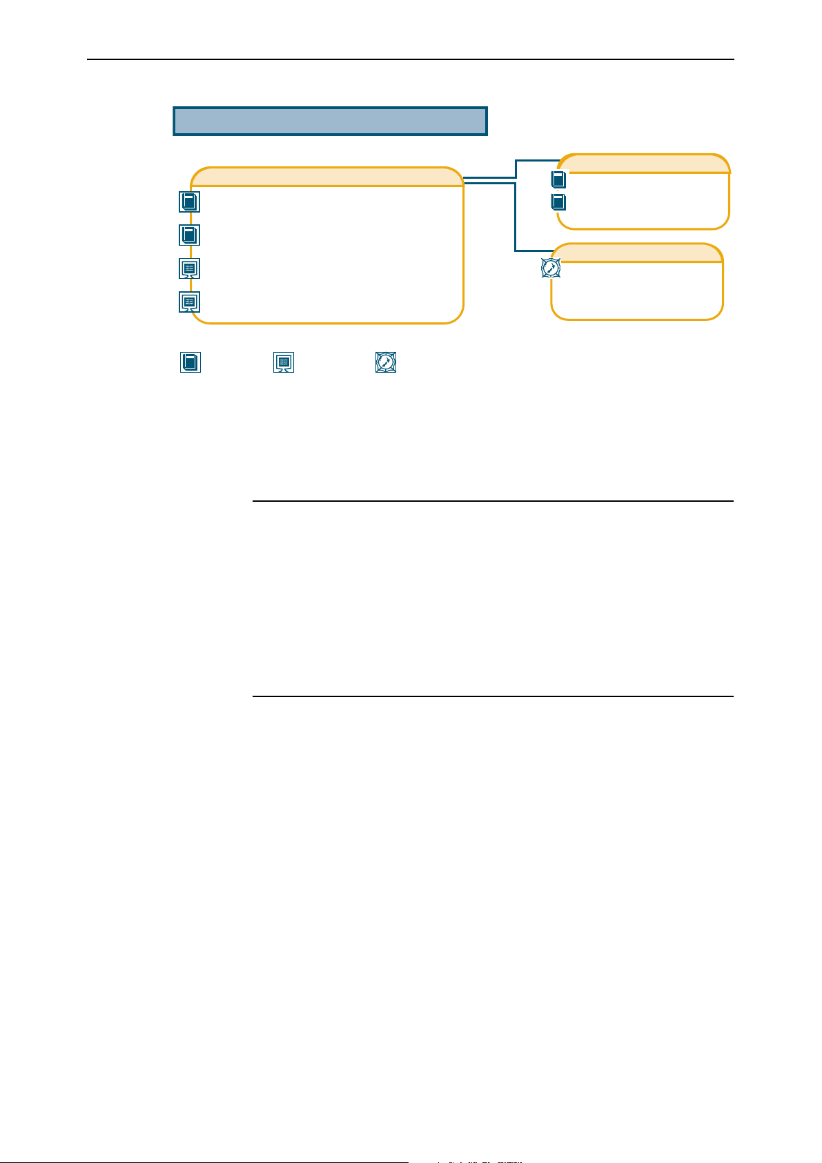
Documentation Roadmap
AT-8900 Series
AT-8900 Series Safety and Statutory Information Booklet
AT-8900 Series Quick Install Guide
AT-8900 Series Software Reference
AT-8900 Series Hardware Reference
Printed Acrobat PDF
Website
Models Covered By This Guide
This Quick Install Guide includes information on the following models:
■ AT-PWR01 (AC power supply unit)
AT-PWR01
ety and Statutory Information
Saf
Quick Install Guide
General Customer Support
Visit www.alliedtelesyn.co.nz for
the latest documentation, FAQs,
and support information.
■ AT-PWR01 (DC power supply unit)
■ AT-FAN01 (fan only module)
Package Contents
AT-8900 Series switches are supplied with a single power supply unit (PSU),
either AC or DC, and a fan only module (FOM) pre-installed at factory as
standard.
The following items are included with each power supply unit pre-installed in
a AT-8900 Series switch at the factory. Contact your sales representative if any
items are damaged or missing.
■ One AC power cord (AC model)
■ One power cord retaining clip (AC model)
■ One Safety and Statutory Information booklet
■ One warranty card
C613-04049-01 REV B
Page 4

4 AT-PWR01 & AT-PWR01-80
For power supply units purchased separately, the following items are included
with each unit.
■ One power supply unit (AC or DC)
■ One AC power cord (AC model)
■ One power cord retaining clip (AC model)
■ One AT-PWR01 Quick Install Guide
■ One Safety and Statutory Information booklet
■ One warranty card
Installing A Power Supply Unit (PSU)
All AC and DC versions of this equipment must be earthed.
Follow these steps to install a PSU:
1. Read the safety information
The AT-PWR01 Safety and Statutory Information booklet includes all relevant
safety information. A copy of this booklet is supplied with the PSU, and
can also be downloaded from
www.alliedtelesyn.co.nz/support/at8900/
2. Gather the tools and equipment you will need
.
To loosen or secure the PSU’s mounting screws you will need a Phillips #2
screwdriver.
To install a DC version of the PSU, you will need an appropriate DC power
source, DC supply cable, ring connectors, and a crimp tool.
3. Unpack the PSU
In an antistatic environment, remove the PSU from its packing material. Be
sure to observe ESD precautions.
Verify the package contents. If any items are damaged or missing, contact
your sales representative.
Do not attempt to install a power supply unit without observing correct
antistatic procedures. Failure to do so may damage the power supply unit or
switch. If you are unsure what the correct procedures are, contact your
authorised Allied Telesyn distributor or reseller.
4. For AC models only, fit the power cord retaining clip
There is one retaining clip for the AC power inlet on the PSU.
C613-04049-01 REV B
Page 5

Quick Install Guide 5
5. Remove an existing PSU or FOM
Disconnect the power cord before removing the PSU.
The PSU and switch may overheat or be damaged by dust and debris if bays are
left uncovered.
Loosen the two Phillips screws on the PSU or FOM until the screws
disengage from the switch chassis (see Figure 1).
Figure 1: Captive mounting screws on the AT-PWR01 and AT-FAN01
Switch
Captive screw
PSU
Handle
Captive screw
8948PSU
Slowly and carefully slide the PSU or FOM out of the switch’s power supply
bay.
If you remove a PSU, or FOM, from the switch replace the PSU, or FOM, to prevent
dust and debris from entering the switch chassis and to maintain proper airflow.
6. Insert a PSU
Slowly and carefully slide the PSU into the switch’s power supply bay.
Firmly press the PSU home (until its front panel engages or nearly engages
the switch chassis).
C613-04049-01 REV B
7. Secure the PSU
Keep the PSU in a straight alignment and insert it slowly. Forcing a misaligned
PSU is likely to damage the chassis and PSU.
Tighten the two Phillips screws on the PSU’s faceplate (see Figure 1 on
page -5).
Page 6

6 AT-PWR01 & AT-PWR01-80
8. Apply power to the PSU
For AC Models:
Read the AT-PWR01 Safety and Statutory Information booklet before
connecting a PSU to an external AC power source. A copy of the safety
booklet is included with each PSU.
Plug the provided AC power cord into the AC power inlet on the rear
panel of the PSU and connect the PSU to the mains power supply.
Important information for service personnel only:
• CAUTION: double pole/neutral fusing
• The ratings of fuses FH101 and FH102 is 250 V, 5 A
For DC models:
Read the AT-PWR01 Safety and Statutory Information booklet before
connecting a PSU to a DC power source. A copy of the safety booklet is
included with each PSU.
Only trained and qualified personnel should connect a DC power supply.
For centralized DC power connection, the switch should be installed only in
Restricted Access Areas (Dedicated Equipment Rooms, Equipment Closets, or
the like) in accordance with Articles 110-16, 110-17, and 110-18 of the National
Electrical Code, ANSI/NAPA 70.
DC supply cable specifications:
• Three core cable is required
• Minimum core size: 3.3 mm
2
(12 AWG) high strand count copper wire
• Minimum cable rating: 600 V, 90 degrees Celsius
DC power supply specifications:
• 40 to 60 V, 48 V nominal
• Supports either positive grounded or negative grounded operation
Circuit protection:
• 10 Amp certified/Listed circuit breaker is required for branch circuit
protection
To connect the DC supply:
Ensure that the supply cable is not live.
1. Remove the transparent protective terminal cover.
2. Strip the supply cable wires to expose 7.5mm (0.31 in.) of bare
conductor. Terminate with JST FN5.5-5 or equivalent, using a crimp
tool.
3. Connect the ground wire to the ground terminal. Terminals can be
identified by the diagram on the switch’s rear panel. Tighten the
terminal to between 2.4 and 4.0 Nm (21.3 and 35.4 lbf in).
C613-04049-01 REV B
Page 7

Quick Install Guide 7
4. Connect the positive feed to the + (positive) terminal and the negative
feed to the - (negative) terminal. Tighten the terminals to between 2.4
and 4.0 Nm (21.3 and 35.4 lbf in).
Check that the PSU terminals are wired to the correct polarity. A PSU will be
damaged if incorrectly connected.
5. Ensure there are no exposed cable strands.
6. Replace the transparent plastic terminal cover.
The transparent plastic terminal cover must be replaced.
7. Secure the supply cable (to the rack framework or similar object) so that
the connections are isolated from any force applied to the cable.
8. Ensure the circuit breaker (for the supply circuit) and the Run/Standby
switch (on the switch) are in the OFF position.
9. Connect the supply cable wires to the circuit breaker.
10. Switch the power switch to the ON position.
9. Check the PSU LEDs
Each PSU has LEDs that indicate the PSU’s operational status.
Once you have inserted the PSUs and powered on the chassis, check the
LEDs for correct operation using the table below as a guide (see Table 2).
Table 2: LEDs on AC and DC PSUs
LED State Function
Fault Red There is either a fan failure, or the temperature has
exceeded the specified limit of 75º C (167
PWR Green A PSU is installed and supplying power to the switch.
º F).
On the front panel of the switch there are two LEDs that indicate the
operational status of each PSU installed in the switch (see Table 3).
C613-04049-01 REV B
Page 8

8 AT-PWR01 & AT-PWR01-80
Table 3: PSU LEDs found on all AT-8900 Series switches
PSU 1 Green PSU 1 is installed and supplying power to the
switch, and the voltage output is within
specification.
Red PSU 1 is installed in the switch, a fan has failed,
or the PSU has exceeded its recommend
temperature threshold of 75º C (167º F).
A FOM is installed in the switch and a fan has
failed.
The bay is empty (no PSU or FOM installed).
Not lit A FOM is installed and the fan is good.
PSU 2 Green PSU 2 is installed and supplying power to the
switch, and the voltage output is within
specification.
Red PSU 2 is installed in the switch, a fan has failed,
or the PSU has exceeded its recommend
temperature threshold of 75º C (167º F).
A FOM is installed in the switch and a fan has
failed.
The bay is empty (no PSU or FOM installed).
Not lit A FOM is installed and the fan is good.
If the PSU does not function as expected, follow these steps:
1. Check all cable connections are correct and secure.
2. For DC models, check that the standby switch has been pressed and is in the
ON position.
For AC models, check the PSU is receiving the correct AC voltage.
3. If the LEDs indicate a PSU fault, replace the PSU or have it serviced by
authorised service personnel.
More troubleshooting information can be found in the AT-8900 Series Hardware
Reference.
C613-04049-01 REV B
Page 9

Quick Install Guide 9
Where to Find More Information
Sources of further information:
■ The AT-PWR01 Statutory and Safety Information booklet, which provides
safety and statutory information for the power supply units.
■ The AT-8900 Series Statutory and Safety Information booklet, which provides
important safety information and statutory declarations for AT-8900 Series
switches.
■ The AT-8900 Series Quick Install Guide, which outlines the procedure for
installing a AT-8900 Series switch.
■ The AT-8900 Series Hardware Reference, which includes detailed hardware
specifications for the AT-8900 Series switch.
■ The AT-8900 Series Software Reference, which provides detailed information
on configuring the AT-8900 Series switch and its software.
You can download these documents from
www.alliedtelesyn.co.nz/support/at8900/
.
C613-04049-01 REV B
 Loading...