

Page 1

◆
PowerBlade
Chassis
®
AT-PBC18
Installation
Guide
PN 613-50144-00 Rev C
Page 2

Copyright 2002 Allied Telesyn, Inc.
960 Stewart Drive Suite B, Sunnyvale, CA 94085 USA
All rights reserved. No part of this publication may be reproduced without prior written permission from Allied Telesyn, Inc.
Netscape Navigator is a regist ered trademark of Netscape Communications Corporation. All other product names, company
names, logos or other designations mentioned herein are trademarks or registered trademarks of their respective owners.
Allied Telesy n, Inc. rese rves t he r ight t o mak e chan ges i n spec ifica tion s and ot her i nform ation c ont ained i n this doc ument w ithout
prior written notice. The information provided herein is subject to change without notice. In no event shall Allied Telesyn, Inc. be
liable for any incidental, special, indirect, or consequential damages whatsoever, including but not limited to lost profits, arising
out of or related to this manual or the information contained herein, even if Allied Telesyn, Inc. has been advised of, known, or
should have known, the possibility of such damages.
Page 3

Electrical Safety and Emission Compliance
Statement
Standards: This product meets the following standards:
U.S. Federal Communications Commission
Radiated Energy
Note: This equipment has been tested and found to comply with the limits for a Class A digital device pursuant to Part 15 of the
FCC Rules. These limits are designed to provide reasonable protection against harmful interference when the equipment is
operated in a commercial environment. This equipment generates, uses, and can radiate radio frequency energy and, if not
installed and used in accordance with this instruction manual, may cause harmful interference to radio communications.
Operation of this equipment in a res identia l area is li kely to caus e harmful inte rference in which case t he user will be required t o
correct the interference at his own expense.
Note: Modifications or changes not expressly approved by the manufacturer or the FCC can void your right to operate this
equipment.
Industry Canada
This Class A digital apparatus meets all requirements of the Canadian Interference-Causing Equipment Regulations.
Cet appareil numérique de la classe A respecte toutes les exigences du Règlement sur le matériel brouilleur du Canada.
RFI Emission EN55022 Class A, EN61000-3-2, EN61000-3-3
Warning: In a domestic environment this product may cause radio interference in which case the user may be required to take
adequate measures.
Immunity EN55024
Electrical Safety EN60950, UL 1950 (UL/cUL)
Laser EN60825
Important: Appendix A contains translated safety statements for installing this equipment. When you see the
A for the translated safety statement in your language.
Wichtig: Anhang A enthält übersetzte Sicherheitshinweise für die Installation dieses Geräts. Wenn Sie
Anhang A den übersetzten Sicherheitshinweis in Ihrer Sprache nach.
Vigtigt: Tillæg A indeholder oversatte sikkerhedsadvarsler, der vedrører installation af dette udstyr. Når De ser symbolet
De slå op i tillæg A og finde de oversatte sikkerhedsadvarsler i Deres eget sprog.
Belangrijk: Appendix A bevat vertaalde veiligheidsopmerkingen voor het installeren van deze apparatuur. Wanneer u de
raadpleeg Appendix A voor vertaalde veiligheidsinstructies in uw taal.
Important: L'annexe A contient les instructions de sécurité relatives à l'installation de cet équipement. Lorsque vous voyez le
symbole
Tärkeää: Liite A sisältää tämän laitteen asentamiseen liittyvät käännetyt turvaohjeet. Kun näet
turvaohjetta liitteestä A.
Importante: l’Appendice A contiene avvisi di sicurezza tradotti per l’installazione di questa apparecchiatura. Il simbolo
di consultare l’Appendice A per l’avviso di sicurezza nella propria lingua.
Viktig: Tillegg A inneholder oversatt sikkerhetsinformasjon for installering av dette utstyret. Når du ser
for å finne den oversatte sikkerhetsinformasjonen på ønsket språk.
Importante: O Anexo A contém advertências de segurança traduzidas para instalar este equipamento. Quando vir o símbolo
leia a advertência de segurança traduzida no seu idioma no Anexo A.
Importante: El Apéndice A contiene mensajes de seguridad traducidos para la instalación de este equipo. Cuando vea el símbolo
!, reportez-vous à l'annexe A pour consulter la traduction de ces instructions dans votre langue.
! 2
! 3
! 4
! 5
!-symbolin, katso käännettyä
! 1
!, go to Appendix
! sehen, schlagen Sie in
!, skal
! ziet,
!, indica
!, åpner du til Tillegg A
!,
!, vaya al Apéndice A para ver el mensaje de seguridad traducido a su idioma.
Obs! Bilaga A innehåller översatta säkerhetsmeddelanden avseende installationen av denna utrustning. När du ser
till Bilaga A för att läsa det översatta säkerhetsmeddelandet på ditt språk.
!, skall du gå
3
Page 4

Page 5

Table of Contents
Preface ......................................................................................................................................................................................................................9
How This Guide is Organiz ed .............................................................................................................................................................................9
Where to Find Related Guides .........................................................................................................................................................................11
Document Conventions ................................................ ....................................................................................................................................12
Contacting Allied Telesyn Technical Support ................ ............................................................................................................................13
Online Support..............................................................................................................................................................................................13
Telephone Suppor t........ ......................... .....................................................................................................................................................13
E-mail Support..... ..........................................................................................................................................................................................13
Returning Products .............................................................................................................................................................................................14
FTP Server ...............................................................................................................................................................................................................15
For Sales or Corporate Information ...... .........................................................................................................................................................16
Tell Us What You Think ......................................................................................................................................................................................17
Chapter 1
Overview ................................................................................................................................................................................................................19
PowerBlade PBC18 Chassis ...............................................................................................................................................................................19
Key Features...................................................................................................................................................................................................20
Status LEDs .....................................................................................................................................................................................................21
Power Supply.................................................................................................................................................................................................22
Optional Management Module...............................................................................................................................................................23
Chapter 2
Installing the Chassis on a Desktop or in a Rack .................................................................................................................................25
Overview .................................................................................................................................................................................................................25
Verifying Package Contents......................................................................................................................................................................25
Preparing the Site......................................................... .................................................... ............................................................................26
Reviewing Safety Precaut io ns............. .....................................................................................................................................................26
Installing the Chassis on a Desktop ............................................................................. ..................................................................................28
Installing the Chassis in a Rack ................................................................................. .......................................................................................29
Warranty Registration .........................................................................................................................................................................................31
Chapter 3
Installing a Power Supply Module .............................................................................................................................................................33
Overview .................................................................................................................................................................................................................33
Installing a Main Power Supply ............................... ........................................................................................................................................35
Installing an Optional Power Su pply .................................................................................. ..........................................................................40
Hot Swapping a Power Supply ................... .....................................................................................................................................................42
5
Page 6

Table of Contents
Chapter 4
Installing a Media Converter Module ......................................................................................................................................................43
Overview ................ ............ ............ ................. ............ ............. ................ ............. ..................................................................................................44
Common Features ...............................................................................................................................................................................................45
MDI/MDI-X......................................................................................................................................................................................................45
Link Test/MissingLink......................... ........................................................................................................................................................46
Half-duplex and Full-duplex Mode .......................................................................................................................................................48
Network Topologies ....................... ............................................................................................................................................................49
AT-PB10 Series Modules ...................................................................................................................................................................................51
Status LEDs.................... .................................................................................................................................................................................52
BNC Termination Switch (AT-PB15 only).............................................................................................................................................53
J5 Jumper (AT-PB15 only).........................................................................................................................................................................54
Cable Specifications....................................................................................................................................................................................55
AT-PB100 Series Modules ............................. ...................................................... ..............................................................................................56
Status LEDs.................... .................................................................................................................................................................................58
Cable Specifications....................................................................................................................................................................................58
100Base-FX Fiber Optic Port Specifications.......................................................................................................................................61
Auto-negotiation Swit ch........... ................................................................................................................................................................63
AT-PB300 Series Modules ............................. ...................................................... ..............................................................................................65
Status LEDs.................... .................................................................................................................................................................................66
Cable Specifications....................................................................................................................................................................................67
Auto-negotiation Swit ch........... ................................................................................................................................................................68
AT-PB1000 Series Module ....................................................................................................... .........................................................................69
Status LEDs.................... .................................................................................................................................................................................70
Link Test Back-to-back/ St andalone Button.................... ...................................................................................................................71
Cable Specifications....................................................................................................................................................................................71
Installing a Media Converter ...........................................................................................................................................................................73
Hot Swapping a Media Converte r ............. ....................................................................................................................................................76
Chapter 5
Installing a Switch Module ...........................................................................................................................................................................77
Overview ................ ............ ............ ................. ............ ............. ................ ............. ..................................................................................................77
Features...........................................................................................................................................................................................................79
Switch Performance....................................................................................................................................................................................80
Frame Processing .........................................................................................................................................................................................80
Address Recognition and Filte ring........................................................................................................................................................80
Status LEDs.................... .................................................................................................................................................................................81
MDI/MDI-X......................................................................................................................................................................................................81
DIP Switches............. .....................................................................................................................................................................................82
J6 Jumper........................................................................................................................................................................................................83
Network Topologies ....................... ............................................................................................................................................................84
Cable Specifications....................................................................................................................................................................................85
Installing a Switch ...............................................................................................................................................................................................89
Hot Swapping a Switch .....................................................................................................................................................................................92
Chapter 6
Installing an Optional Management Module ......................................................................................................................................93
Overview ................ ............ ............ ................. ............ ............. ................ ............. ..................................................................................................93
Features...........................................................................................................................................................................................................94
Status LEDs.................... .................................................................................................................................................................................95
Reset Button..................................................................................................................................................................................................95
Cable Specifications....................................................................................................................................................................................95
Installing an Optional Managem ent Module ............................. ...............................................................................................................96
6
Page 7

PowerBlade PBC18 Installatio n Guid e
Chapter 7
Troubleshooting ................................................................................................................................................................................................99
Chassis .................... .................... ................. ..................... ................ ..................... ...................................................................................................99
Media Converter or Switch Module ....................... .....................................................................................................................................100
Optional Management Module ..................... ..............................................................................................................................................101
Appendix A
Technical Specifications ..............................................................................................................................................................................103
Physical Characteristics .... ...............................................................................................................................................................................103
Power Requirements .......................................................................................................................................................................................103
Agency Certifications .......................................................................................................................................................................................103
Appendix B
Translated Safety Information .................................................................................................................................................................105
7
Page 8

Page 9

Preface
This installation guide contains instructions on how to install a
PowerBlade PBC18 on a desktop or in a 19-, 23- or 25-inch rack and how
to install the PowerBlade Series Modules.
How This Guide is Organized
This guide contains the following chapters and appendices:
Chapter 1, Overview, describes the features and functions of the
PowerBlade PBC18 Chassis.
Chapter 2, Installing the Chassis on a Desktop or in a Rack, explains how
to install the chassis on a desktop or in a rack.
Chapter 3, Installing a Power Supply Module, explains how to install a
main and optional power supply module into the chassis.
Chapter 4, Installing a Media Converter Module
and functions of the PowerBlade Media Converter modules and contains
installation instructions.
Chapter 5, Installing a Switch Module
functions of the PowerBlade Switch modules and contains installation
instructions.
Chapter 6, Installing an Optional Management Module, contains
instructions on how to install an optional management module.
Chapter 7, Troubleshooting, provides troubleshooting information for
the chassis and modules.
, describes the features and
, describes the features
Appendix A, Technical Specifications, provides technical specifications
for the chassis.
9
Page 10

Preface
Appendix B, Translated Safety Information, contains multi-language
translations of the safety and emission statements in this guide.
10
Page 11

Where to Find Related Guides
The Allied Telesyn web site at www.alliedtelesyn.com offers you an easy
way to access the most recent documentation, software, and technical
information for all of our products.
The following guides are shipped with their respective products and
contain abbreviated versions of the installation procedures:
❑ AT-PBC18 Quick Install Guide,
PN 613-50145-00
❑ AT-PB10 Seri es Quick Install Guide
PN 613-50146-00
❑ AT-PB100 Series Quick install Guide
PN 613-50147-00
❑ AT-PB200 Series Quick Install Guide
PN 613-50148-00
PowerBlade PBC18 Installation Guide
❑ AT-PB300 Series Quick Install Guide
PN 613-50198-00
❑ AT-PB1000 Ser ies Quick Install Guide
PN 613-50149-00
❑ AT-PBM02 Quick Install Guide
PN 613-50172-00
❑ AT-PBPWRAC Quick Install Guide
PN 613-50166-00
❑ AT-PBPWRDC Quick Install Guide
PN 613-50189-00
❑ PowerBlade Rackmount Brackets Quick Install Guide,
PN 613-50230-00
If you purchased a PowerBlade Optional Management module, you will
need the following guide:
❑ AT-S31 User’s Guide
PN 613-50205-00
The AT-S31 User’s Guides provides information and instructions for
managing the chassis and modules. This guide can be downloaded from
Allied Telesyn’s web site.
11
Page 12

Preface
Document Conven tions
This guide uses the following conventions:
Note
Notes provide additional information.
Warning
Warnings inform that performing or omitting a specific action may
result in bodily injury.
Caution
Cautions inform you that performing or omitting a specific action
may result in equipment damage or loss of data.
12
Page 13

PowerBlade PBC18 Installation Guide
Contacting Allied Telesyn Technical Support
You can contact Allied Telesyn technical support online or by telephone
or e-mail.
Online Support You can request technical support online by accessing the Knowledge
Base from our web site at http:\\kb.alliedtelesyn.com. You can use the
Knowledge Base to submit questions to our technical support staff and
review answers to previously asked questions.
Telephone
Support
For Technical Support by telephone, contact Allied Telesyn at one of the
following locations:
Americas
United States, Canada, Mexico,
Central America, South America
Tel: 1 (800) 428-4835
Asia
Singapore, Taiwan, Thailand,
Malaysia, Indonesia, Korea,
Philippines, China,
India, Hong Kong
Tel: (+65) 3815-612
Australia
New Zealand
Tel: 1 (800) 000-880
France
Belgium, Luxembourg, The
Netherlands, Middle East, Africa
Tel: (+33) 1-60-92-15-25
Germany
Switzerland, Austria, Eastern Europe
Tel: (+49) 30-435-900-126
Italy
Spain, Portugal, Greece, Turkey,
Israel
Tel: (+39) 02-41-30-41
Japan
Tel: (+81) 3-3443-5640
United Kingdom
Denmark, Norway, Sweden, Fi nland,
Iceland
Tel: (+44) 1-235-442560
E-mail Support Latin America, Mexico, Puerto Rico, Caribbean, and Virgin Islands
latin_america@alliedtelesyn.com
Europe
support_europe@alliedtelesyn.com
13
Page 14

Preface
Returning Products
Products for return or repair must first be assigned a Return Materials
Authorization (RMA) number. A product sent to Allied Telesyn without a
RMA number will be returned to the sender at the sender’s expense.
To obtain an RMA number, contact Allied Telesyn’s Technical Support at
one of the following locations:
❑ North America
Toll-free: 1-800-762-1664
Fax: 1-425-806-1050
❑ Europe, Africa, and the Middle East
Tel: +44-1793-501401
Fax: +44-1793-431099
❑ Latin America, the Caribbean, an d Virgin Islands
Tel: International code + 425-481-3852
Fax: International code + 425-481-3895
❑ Puerto Rico
Toll-free: 1-800-424-5012, ext 3852
or 1-800-424-4284, ext 3852
❑ Mexico
Toll-free: 800-424-5012, ext 3852
Fax: International code + 425-481-3895
❑ Asia and Southeast Asia
Tel: +65 381-5612
Fax: +65 383-3830
❑ Australia
Toll-free: 1-800-000-880
Fax: 2-9438-4966
❑ New Zealand
Toll-free: 0800-45-5782
14
Page 15

FTP Server
PowerBlade PBC18 Installation Guide
If you need management software for an Allied Telesyn managed device
and you know the file name of the software, you can download the
software by connecting directly to our FTP server at
ftp.alliedtelesyn.com. At login, enter ‘anonymous’ as the user name and
your e-mail address for the password.
15
Page 16

Preface
For Sales or Corporate Information
You can contact Allied Telesyn for sales or corporate information at the
location listed below:
Allied Telesyn, Inc.
19800 North Creek Parkway, Suite 200
Bothell, WA 98011
Tel: 1 (425) 487-8880
Fax: 1 (425) 489-9191
16
Page 17

Tell Us What You Think
If you have any comments or suggestions on how w e might improve this
or other Allied Telesyn documents, please fill out the General Enquiry
Form online. This form can be accessed by selecting “Contact Us” from
www.alliedtelesyn.com.
PowerBlade PBC18 Installation Guide
17
Page 18

Page 19
Chapter 1
Overview
PowerBlade PBC18 Chassis
The PowerBlade PBC18 is an 18-slot chassis that is designed to hold up
to 18 PowerBlade Media Converter modules and Switch modules. The
chassis can be used on a desktop or in a 19-, 23- or 25-inch rack.
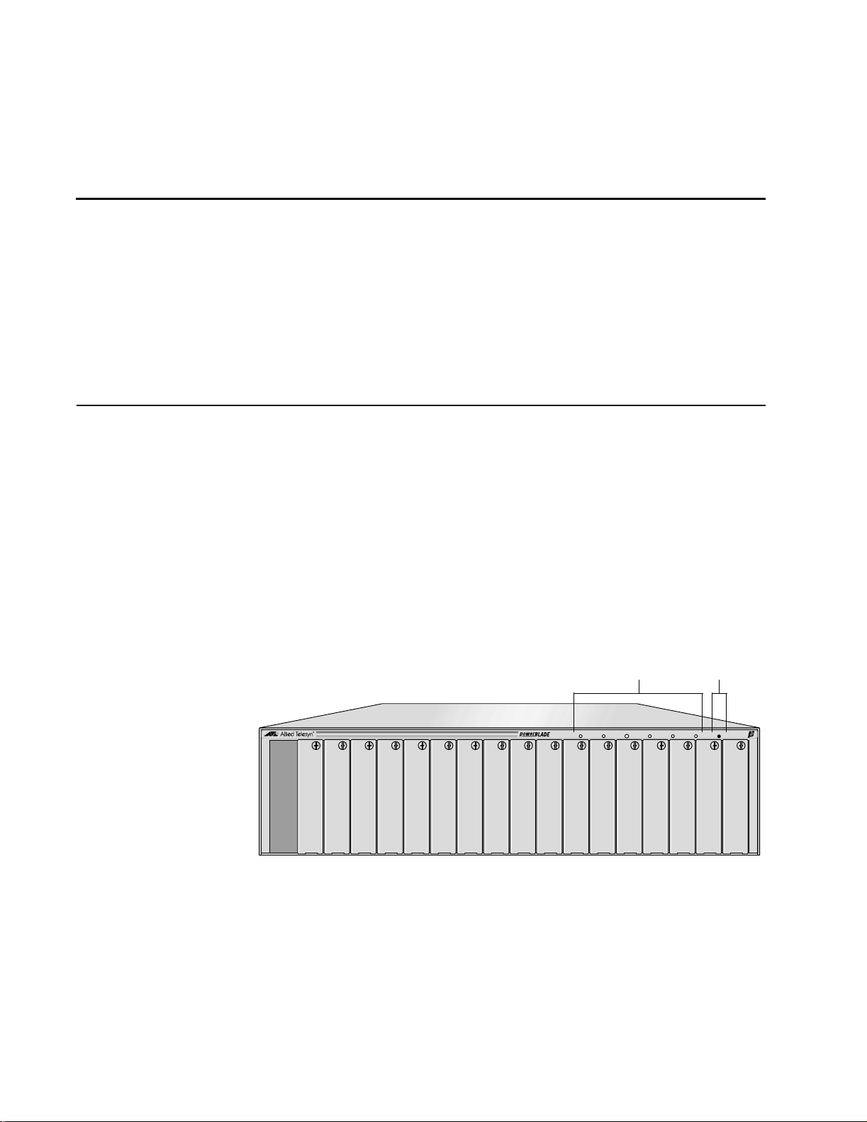
The front of the chassis has 18-slots for the PowerBlade modules along
with six LEDs to notify you of power and management status. The
chassis also has a Reset button that allows you to reset the optional
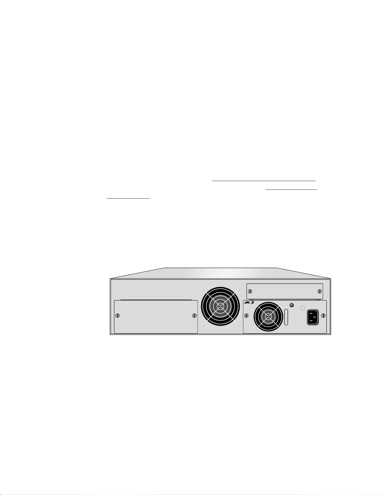
management module. (See Figure 1.) The back of the chassis features a
PWR 1 expansion slot for the main power supply, a PWR 2 expansion slot
for an optional redundant power supply module, and an optional
management module expansion slot. (See Figure 2.)
Status LEDs
PWR 1 PWR 2 STATUS LINK 100M FDX RESET
PBC18
Figure 1 PowerBlade PBC18 Front View
Reset Button
19
Page 20

Overview
Optional Management
Module Expansion Slot
PBM02
Management
PWR
RESET
LNK
STATUS
PWR 2 PWR 1
RS-232 Terminal 10Base-T
MDI
MDI-X
Main Power SupplyOptional Power Supply
Expansion Slot (PWR 2) Expansion Slot (PWR 1)
Figure 2 PowerBlade PBC18 Back View
Key Features ❑ 18-slots to “mix and match” hot swappable PowerBlade modules
❑ LEDs on the front of the chassis for power and management
status
❑ Desktop or rackmount installation
❑ Front mounted Reset button (for use with the management
module only)
20
❑ Hot swappable AC or DC power supplies
❑ An expansion slot for the main power supply and an optional
redundant power supply
❑ One expansion slot for an optional management module
Page 21

PowerBlade PBC18 Installation Guide
Status LEDs Table 1 defines the power and management LEDs.
Table 1 Status LEDs
LED Color Description
Power Modules
PWR1 Green The main power supply is functioning
normally.
PWR2 Green The optional redundant power supply, if
installed, is functioning normally.
Management Module
Status Amber The module is performing a self-test.
Flashing
Amber
The module is d ownloa ding t he f irmwar e from
a host PC.
Red The module or management software is
malfunctioning.
Green The module is installed and online.
LINK Green A valid link has been detected on the RJ-45
port.
100M Not used at this time.
FDX Not used at this time.
21
Page 22
Overview
Power Supply The PowerBlade PBC18 can be either an AC or DC powered chassis. The
expansion slot for the main power supply and the optional redundant
power supply are located on the back of the chassis. Refer to Figure 2 on
page 20.
The main and redundant power supplies can be “hot swapped,”
meaning that should either power supply fail, the failed power supply
can be removed and replaced with a new power module while the
chassis is operating. Network operations will not be interrupted. The
power modules to be hot swapped must be the same type. For example,
both power supplies must be AC or both must be DC.
Powering ON or OFF the chassis depends on the type of power supply
installed. For an AC model, you connect or disconnect the power cord.
For a DC model, you connect or disconnect the DC power cables or
power OFF the DC circuit to which the power supply is connected.
To install a power supp l y , refer to Installing a P ower Supply Modu le on
page 33. For instructions on hot swapping, refer to Hot Swapping a
Power Supply on page 42.
AC Power Supply
The AC power supply operates at 100-120/200-240 V AC with an input
frequency of 50/60 Hz at ± 3%. Figure 3 shows an PowerBlade PBC18
with an AC power supply.
LNK
AC INPUT
100-240AC
50-60Hz
3A MAX.
150W
PBM02
Management
PWR
RESET
STATUS
RS-232 Terminal 10Base-T
MDI
MDI-X
PBPWRAC
PWR 2 PWR 1
Figure 3 PowerBlade PBC18 with an AC Power Supply
22
Page 23
PowerBlade PBC18 Installation Guide
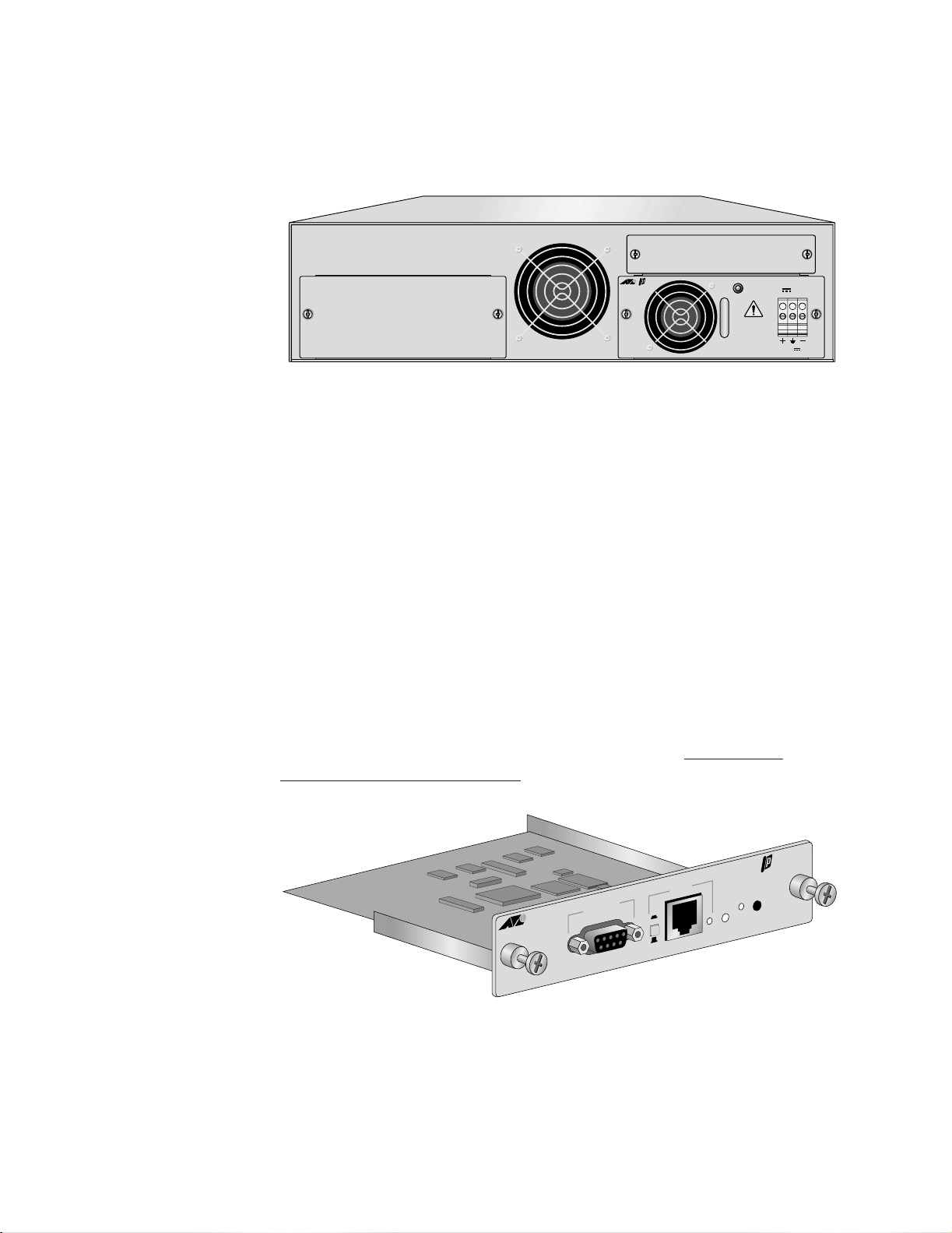
DC Power Supply
The DC power supply has a 48 V DC terminal block connector. Figure 4
shows an PowerBlade PBC18 with a DC power supply.
Optional
Management
Module
PWR
LNK
STATUS
DC INPUT
36-60VDC , 1.0A
PBM02
Management
RESET
PWR 2 PWR 1
PBPWRDC
RS-232 Terminal 10Base-T
MDI
MDI-X
FOR CENTRALIZED DC
POWER CONNECTION,
INSTALL ONLY IN A
RESTRICTED AREA
Figure 4 PowerBlade PBC18 with a DC Power Supply
The management module is an optional module used to monitor the
operating status of the media converters and switches installed the
PowerBlade PBC18. Refer to Figure 2 on page 20 for the location of the
expansion slot. The management module is not required for the chassis
to operate, but it is necessary if you want to locally or remotely monitor
and configure the modules and ports.
The management module features a Link, Power, and Status LEDs, as
well as a Reset button. (See Figure 5.) The LEDs and the Reset button are
duplicated on the front of the chassis for easy monitoring or to reset the
management module. You may need to reset the module after
completing the installation, adding or hot swapping a power supply, or
after upgrading the module’s firmware.
To install an optional management module, ref er to Ins tall in g an
Optional Management Module on page 93.
M
10Base-T
RS-232 Terminal
I
D
M
X
-
I
D
M
R
T
E
W
S
P
E
R
S
U
T
A
T
S
K
N
L
Figure 5 Optional Management Module (AT-PBM02 Model)
PBM02
ent
anagem
23
Page 24

Page 25

Chapter 2
Installing the Chassis on a Desktop
or in a Rack
This chapter contains the following procedures:
❑ Installing the Chassis on a Desktop on page 28
❑ Installing the Chassis in a Rack on page 29
Overview
Verifying Package
Contents
Make sure the following items are included in your package. If items are
missing or damaged, contact your Allied Telesyn sales representative for
assistance.
❑ One PowerBlade PBC18 Chassis
❑ One rackmounting kit
❑ Four protective rubber feet (for desktop installation only)
❑ PowerBlade PBC18 Quick Install Guide
❑ Warranty card
25
Page 26

Installing the Chassis on a Desktop or in a Rack
Preparing the Site Be sure to observe the following guidelines when planning the
installation of your chassis.
❑ Make sure that the chassis’ power is accessible and cables can be
easily connected.
❑ Cables must be away from sources of electrical noise such as
radios, transmitters, broadband amplifiers, power lines,
fluorescent or halogen light fixtures.
❑ Air flow around the chassis and through its vents on the side and
rear should not be restricted.
❑ If you are using the chassis on a desktop, make sure it is placed on
a level, secure surface.
❑ Do not place objects on top of the chassis.
❑ Do not expose the chassis to moisture or water.
❑ Make sure the chassis is in a dust-free environment.
Reviewing Safety
Precautions
❑ Use dedicated power circuits or power conditioners to supply
reliable electrical power to the network devices.
Please review the following safety precautions before you install the
chassis and the PowerBlade modules. (The first warning applies only if
you purchased a module with a fiber optic port.)
Warning
Do not stare into the laser beam. ! 7
Warning
Electric Shock Hazard: To prevent electric shock, do not remove
the cover. There are no user-serviceable parts inside. The unit
contains hazardous voltages and should only be opened by a
trained and qualified technician. ! 8
Warning
Lightning Danger: Do not work on this equipment or cables
during periods of lightning activity. ! 9
26
Caution
Power cord is used as a disconnection device: To de-energize
equipment, disconnect the power cord. ! 10
Page 27

PowerBlade PBC18 Installation Guide
Warning
Electrical-Type Class 1 Equipment: This equipment must be
earthed. The power plug must be connected to a properly wired
earth ground socket outlet. An improperly wired socket outlet
could place hazardous voltages on accessible metal parts. ! 11
Caution
Pluggable Equipment: The socket outlet should be installed near
the equipment and should be easily accessible. ! 12
Caution
Air vents: The air vents must not be blocked on the unit and must
have free access to the room ambient air for cooling. ! 13
Caution
Operating Temperature: This product is designed for a maximum
ambient temperature of 40°C. ! 14
Caution
All Countries: Install this product in accordance with local and
National Electric Codes. ! 15
Caution
Lithium Battery - Should only be changed by trained and qualified
technician.
Danger of explosion if battery incorrectly replaced. Replace only
with the same or equivalent type recommended by the
manufacturer. Dispose of used batteries according to the
manufacturer’s instructions.
Attention: IL y a danger d’explosion s’ily y a remplacement incorrect
de la batterie. Remplacer uniquement avec une batterie du même
type ou d’un type recommandé par le constructeur. Mettre au rébut
les batteries usagés conformement aux instructions du fabricant.
! 21
27
Page 28
Installing the Chassis on a Desktop or in a Rack
Installing the Chassis on a Desktop
This section explains how to install the chassis on a desktop. To install
the chassis in a rack, refer to Installing the Chassis in a Rack on page 29.
For desktop installation, perform the following procedure:
1. Remove all the items from the shipping package and store the
packaging material in a safe location. In case you need to return the
chassis to Allied Telesyn, you will need to ship the unit back using as
much of the original packaging material as possible.
2. Place the chassis upside down on a level, secure surface.
3. Attach one of the protective rubber feet to each corner of the
chassis, then turn the unit right side up. See Figure 6.
T
E
S
E
R
X
D
MF
0
0
1
K
IN
L
S
U
T
A
T
S
2
R
W
P
1
R
W
P
8
1
C
B
P
Figure 6 Attaching the Protective Rubber Feet
4. Apply power to the chassis by connecting the AC power cord or DC
wires. Refer to Chapter 3, Install ing a Power Supply Module
on page
33 for instructions.
28
Page 29
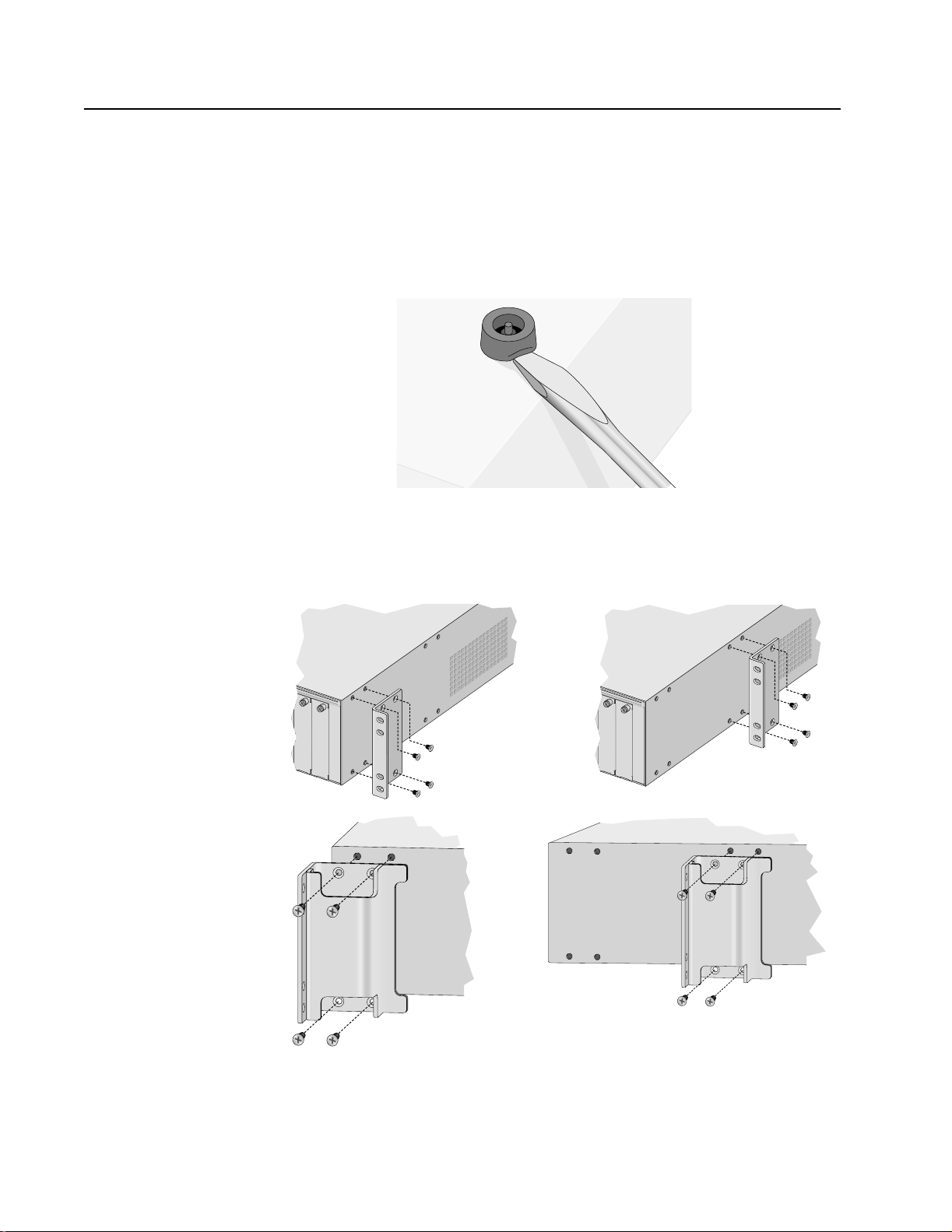
Installing the Chassis in a Rack
The chassis can be installed in a 19-, 23-, or 25-inch rack. It is
recommended that you install the chassis in the rack before installing
the PowerBlade modules.
For rackmount installation, perform the following procedure:
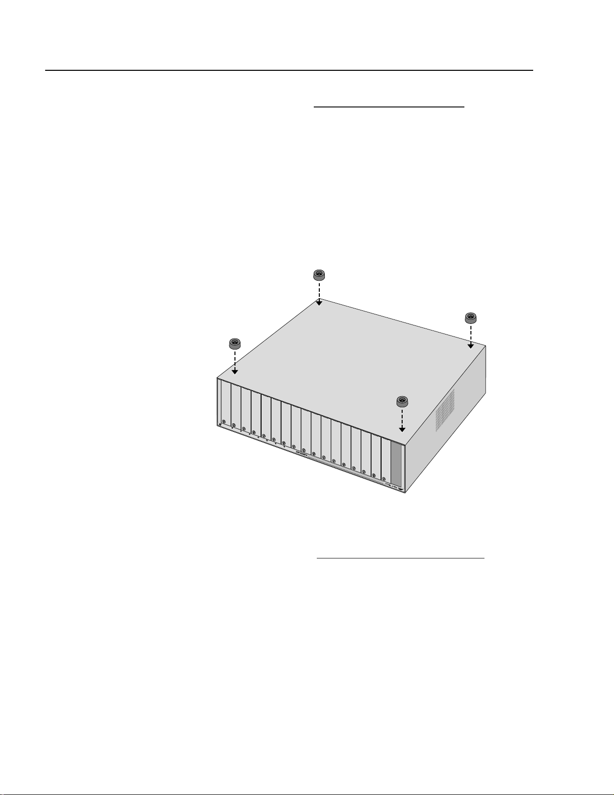
1. Remove the protective rubber feet from the bottom of the chassis, if
attached, as shown in Figure 7.
PowerBlade PBC18 Installation Guide
Figure 7 Removing the Protective Rubber Feet
2. Attach the brackets to either the front or middle of the side of the
chassis, as shown in Figure 8.
19-inch Bracket
Installation A
19-inch Bracket
Installation B
23- and 25-inch
Bracket Installation B
23- and 25-inch
Bracket Installation A
Figure 8 Attaching the Brackets to the PowerBlade PBC18
29
Page 30
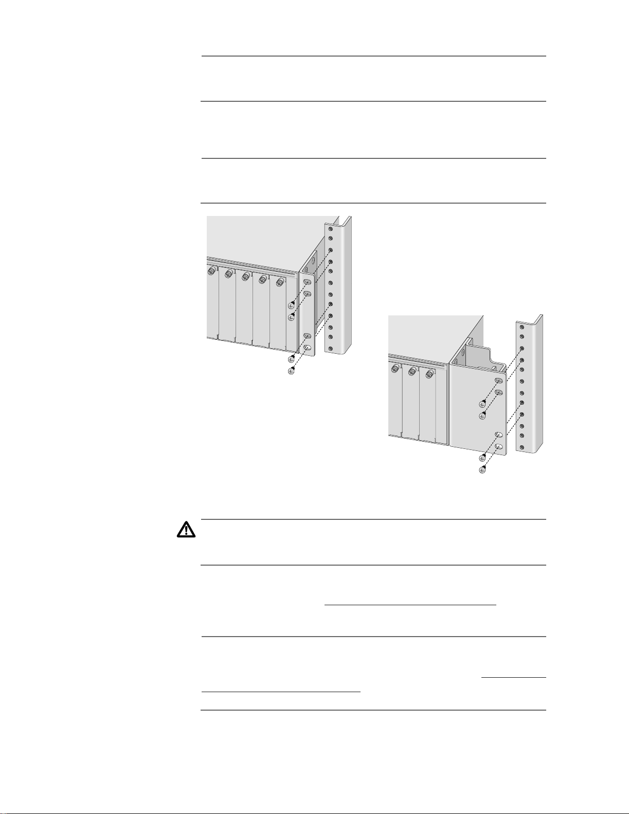
Installing the Chassis on a Desktop or in a Rack
Note
The chassis may be heavy and awkward to lift. It is recommended
that you get assistance with the next step.
3. Attach the chassis to the rack with 4 screws (not provided) for each
side. Refer to Figure 9.
Note
The brackets are designed to be installed in the center of a 3U high
opening on a standard rack.
19-inch Version
23- and 25-inch Version
Figure 9 Installing the Chassis in a Rack
Caution
Power cord is used as a disconnection device. To de-energize
equipment, disconnect the power cord. ! 10
4. Apply power to the chassis by connecting the AC power cord or DC
wires. Refer to Chapter 3, Install ing a Power Supply Module on page
33 for instructions.
Note
If you purchased an optional management module, install the
module before applying power to the chassis. Refer to Installing an
Optional Management Module on page 93 for installation
instructions.
30
Page 31

Warranty Registration
When you have finished installing the product, you should register your
product by completing the enclosed warranty card and sending it in.
PowerBlade PBC18 Installation Guide
31
Page 32

Page 33

Chapter 3
Installing a Power Supply Module
This chapter describes of the features and functions of the PowerBlade
Power Supply modules. This chapter also contains the following
procedures:
❑ Installing a Main Power Supply on page 35
❑ Installing an Optional Power Supply on page 40
❑ Hot Swapping a Power Supply on page 42
Overview
There are two types of power modules available for the PowerBlade
PBC18: an AT-PBPWRAC and an AT-PBPWRDC. The AT-PBPWRAC is an AC
power supply module and the AT-PBPWRDC is a DC power supply
module.
Figure 10 illustrates an AC power supply module.
Power LED
PBPWRAC
AC INPUT
100-240AC
50-60Hz
3A MAX.
150W
AC Connector
Figure 10 AT-PBPWRAC Power Supply Module
33
Page 34

Installing a Power Supply Module
Figure 11 illustrates a DC power supply module.
Power LED
PBPWRDC
FOR CENTRALIZED DC
POWER CONNECTION,
INSTALL ONLY IN A
RESTRICTED AREA
DC INPUT
DC Terminal
Block
36-60VDC , 1.0A
Figure 11 AT-PBPWRDC Power Supply
An optional power supply share the load of powering the chassis with
the main power supply. This is known as “load-sharing.” In the event the
main power supply fails, the optional power supply will provide full
power to the chassis, thereby preventing a system failure.
The main and optional power supplies can be “hot swapped,” meaning
that should either power supply fail, the failed power supply can be
removed and replaced with a new power module while the chassis is
operating. Network operation will not be interrupted. The power
modules to be hot swapped must be the same type. You cannot install
an AC power supply and a DC power supply in the same chassis.
The back of the PowerBlade PBC18 has two expansion slots: one for the
main power supply and one for the optional power supply. The power
module installed in the PWR 1 expansion slot is for the main power
supply. The power module installed in the PWR 2 expansion slot is for
the optional power supply.
34
Powering ON or OFF the chassis depends on the type of power supply
installed. For an AC model, you connect or disconnect the power cord.
For a DC model, you connect or disconnect the DC power cables or
power OFF the DC circuit to which the power supply is connected.
Page 35

Installing a Main Power Supply
To install a main power supply, perform the following procedure:
1. Remove the PWR 1 blank faceplate from the back of the chassis by
loosening the two thumbscrews, as shown in Figure 12.
PowerBlade PBC18 Installation Guide
t
PBM02
n
e
m
e
g
a
n
a
M
-T
se
a
B
0
1
l
a
in
m
r
e
T
2
3
2
S-
R
R
PW
ESET
R
I
D
M
S
U
T
A
ST
K
N
L
I-X
D
M
Figure 12 Removing the Main Power Supply Blank Faceplate
2. Remove the power supply from the shipping package and store the
packaging material in a safe location.
3. Slide the power supply into the expansion slot, gently seating the
power supply’s connector into the chassis’ backplane. See Figure 13.
t
PBM02
n
e
m
e
g
a
n
a
M
-T
se
a
B
0
1
l
a
n
i
m
r
e
T
2
3
2
S-
R
R
PW
ESET
R
I
D
M
S
U
T
A
ST
K
N
L
I-X
D
M
Figure 13 Installing the Main Power Supply
4. Secure the power supply to the chassis by tightening the two
thumbscrews.
35
Page 36

Installing a Power Supply Module
Caution
Power cord is used as a disconnection device: To de-energize
equipment, disconnect the power cord. (AC model only.) ! 10
5. For an AC powered chassis, plug one end of the power cord to the
back of the power supply and plug the other end to a power outlet.
Proceed to Step 7 on page 39 for further instructions.
Note
If you purchased an optional management module, install the
module before applying power to the chassis. Refer to Installing an
Optional Management Module on page 93 for installation
instructions.
6. For a DC powered chassis, perform the following steps:
a. Before attaching wires to the DC terminal block on the power
supply module, review the following warning:
Warning
As a safety precaution, a 10 Amp circuit breaker should be installed
at the supply end of the cable to be used with this LAN equipment.
Always connect the wiring to the LAN equipment first before
connecting the wiring to the breaker. To avoid the danger of
physical injury from electrical shock, do not work with HOT feeds.
Always be sure that the breaker is in the OFF position before
connecting the wiring to the breaker. ! 16
36
Page 37

PowerBlade PBC18 Installation Guide
TRALIZED DC
L ONLY IN A
CTED AREA
36-60VDC , 1.0A
DC INPUT
b. Identify the positive, frame ground and negative terminals
using the positive (+), ground ( ), and negative (-) symbols on
the DC power supply. See Figure 14.
PBM02
Management
PWR
RESET
LNK
STATUS
DC INPUT
36-60VDC , 1.0A
Negative
PWR 2 PWR 1
Positive
PBPWRDC
RS-232 Terminal 10Base-T
MDI
MDI-X
FOR CENTRALIZED DC
POWER CONNECTION,
INSTALL ONLY IN A
RESTRICTED AREA
Ground
Figure 14 Positive, Ground, and Negative Symbols
c. Strip the three wires in the cable tray coming from the DC input
power source to 8 millimeters ± 1 millimeters (0.31 inches ±
0.039 inches) using a 14-gauge wire-stripping tool. See Figure
15.
Warning
Do not strip more than the recommended amount of wire.
Stripping more than the recommended amount can create a safety
hazard by leaving exposed wire on the terminal block after
installation. ! 17
8 mm ± 1 mm
(0.31 in ± 0.039 in)
Figure 15 Stripped Wire
d. Connect the frame ground wire to the terminal marked with the
ground symbol by inserting the wire into the terminal block and
tightening the connection with a flathead screwdriver. See
Figure 16.
37
Page 38

Installing a Power Supply Module
36-60VDC , 1.0A
DC INPUT
Warning
When installing this equipment, always ensure that the frame
ground connection is installed first and disconnected last. ! 18
LNK
STATUS
PBM02
Management
PWR
RESET
DC INPUT
36-60VDC , 1.0A
PWR 2 PWR 1
PBPWRDC
RS-232 Terminal 10Base-T
MDI
MDI-X
FOR CENTRALIZED DC
POWER CONNECTION,
INSTALL ONLY IN A
RESTRICTED AREA
Figure 16 Connecting the Stripped Wire
e. Connect the positive feed wire to the terminal block marked +
(positive).
f. Connect the negative feed wire to the terminal block marked -
(negative).
38
Warning
Safety Hazard - Check to see if there are any exposed copper
strands coming from the installed wires. When this installation is
done correctly there should be no exposed copper wire strands
extending from the terminal block. Any exposed wiring can
conduct harmful levels of electricity to persons touching the wires.
! 19
g. Secure the tray supply cable near the rack using multiple cable
ties (not provided). This will help minimize the chance of the
connections being disturbed by casual contact with the wiring.
It is recommended that you use at least four cable ties 10
centimeters (4 inches) apart with the first one located within 15
centimeters (6 inches) of the terminal block.
Page 39

PowerBlade PBC18 Installation Guide
Note
This system will work with a positive grounded or negative
grounded DC system. ! 20
h. Connect the three DC wires to a DC power source.
7. Check that the PWR1 LED on the front of the chassis is green. If the
LED is OFF, refer to Troubleshooting on page 99 for assistance.
The PowerBlade PBC18 is now ready for use. Proceed to Installing a
Media Converter Module on page 43 or Installing a Switch Module on
page 77 for further instructions.
39
Page 40

Installing a Power Supply Module
Installing an Optional Power Supply
To install an optional power supply, perform the following procedure:
Note
It is recommended that you connect the main and optional power
supplies to power outlets on separate power circuits to protect
your chassis from a loss of power due to a power circuit failure.
1. Remove the PWR 2 blank faceplate from the back of the chassis by
loosening the two thumbscrews, as shown in Figure 17.
PBPWRAC
02
M
B
t
P
n
e
m
e
g
na
a
M
T
-
e
s
a
B
0
1
l
a
n
i
m
r
e
T
2
3
2
-
S
R
R
T
E
W
S
P
E
R
I
D
M
S
U
T
A
T
S
K
N
L
X
-
I
D
M
T
U
P
N
I
C
A
C
A
0
4
-2
0
0
1
z
H
0
-6
0
5
.
X
A
M
A
3
W
0
5
1
PWR 1
PWR 2
Figure 17 Removing the Optional Power Supply Blank Faceplate
2. Remove the power supply from the shipping package and store the
packaging material in a safe location.
3. Slide the optional power supply into the expansion slot, gently
seating the power supply’s connector into the chassis’ backplane.
See Figure 18.
PBM02
Management
T
-
e
s
a
B
0
1
l
a
n
i
m
r
e
T
2
3
2
-
S
R
C
A
R
W
P
B
P
R
T
E
W
S
P
E
R
I
D
M
S
U
T
A
T
S
K
N
L
I-X
D
M
T
U
P
N
I
C
A
C
A
0
4
2
-
0
0
1
z
H
0
6
-
0
5
.
X
A
M
A
3
W
0
5
1
40
PWR 2
PWR 1
T
U
P
N
I
C
A
R
W
P
B
P
C
A
C
A
0
4
2
-
0
0
1
z
H
0
6
-
0
5
.
X
A
M
A
3
W
0
5
1
Figure 18 Installing an Optional Power Supply
Page 41

PowerBlade PBC18 Installation Guide
4. Secure the optional power supply to the chassis by tightening the
two thumbscrews.
Note
It is recommended that you connect the main and optional power
supplies to power outlets on separate power circuits to protect
your chassis from a loss of power due to a power circuit failure.
5. Apply power to the module by connecting the appropriate power
cord or wires. Refer to , Step 5 on page 36 for an AC unit or Step 6 on
page 36 for a DC unit.
6. Check that the PWR LED on the front of the chassis is green. If the
LED is OFF, refer to Troubleshooting on page 99.
The PowerBlade PBC18 is now ready for use. Proceed to Installing a
Media Converter Module on page 43 or Installing a Switch Module on
page 77 for further instructions.
41
Page 42

Installing a Power Supply Module
Hot Swapping a Power Supply
Both the main and optional power supplies are hot swappable. The
power modules to be hot swapped must be the same type. You cannot
install an AC power supply and a DC power supply in the same chassis.
1. To remove a failed power supply, you must power OFF the
appropriate power source. To do this, perform one of the following:
❑ For an AC model, unplug the power cord from the power outlet
and then unplug the power cord from the failed module.
❑ For a DC model, follow the steps below:
Warning
When installing this equipment, always ensure that the frame
ground connection is installed first and disconnected last. ! 18
a. Remove the positive and negative feed wires from the terminal
block by loosening the screws to the wire connections with a
flathead screwdriver.
b. Remove the frame ground wire from the terminal block by
loosening the screw to the wire connection with a flathead
screwdriver.
2. Loosen the two thumbscrews and slide out the failed power supply.
3. Remove the new power supply from the shipping package and
store the packaging material in a safe location.
4. Slide the new power supply into the expansion slot, gently seating
the power supply’s connector into the chassis’ backplane.
5. Secure the new power supply to the chassis by tightening the two
thumbscrews.
Note
It is recommended that you connect the main and optional power
supplies to power outlets on separate circuits to protect your
chassis from loss of power due to a power circuit failure.
6. Apply power to the new module by connecting the AC power cord
or DC wires. Refer to Step 5 on page 36 for an AC unit or Step 6 on
page 36 for a DC unit.
42
7. Check that the PWR LED on the font of the chassis is green. If the
LED is OFF, refer to Troubleshooting on page 99.
The new power supply is now ready for use.
Page 43

Chapter 4
Installing a Media Converter Module
This chapter describes the features and functions of the following
PowerBlade Media Converter modules:
❑ AT-PB10 Series Modules on page 51
❑ AT-PB100 Series Modules on page 56
❑ AT-PB300 Series Modules on page 65
❑ AT-PB1000 Series Module on page 69
This chapter also contains the following procedures:
❑ Installing a Media Converter on page 73
❑ Hot Swapping a Media Converter on page 76
43
Page 44

Installing a Media Converter Module
Overview
The PowerBlade Media Converters are designed to extend the distance
of your network by interconnecting LAN devices that are physically
separated by large distances.
There are several different PowerBlade modules that you can “mix and
match” in a chassis. The media converter modules come in a variety of
port configurations, connectors types, and operating distances.
PowerBlade Media Converters are available with an RJ-45 twisted pair
connector and either an BNC standard thin Ethernet connector or a FJ,
LC, MT-RJ, SC, ST, or VF-45 fiber optic connector. Depending on the
model, the media converters feature a maximum operating distance of
100 meters (328 feet) to 100 kilometers (62 miles).
44
Page 45

PowerBlade PBC18 Installation Guide
Common Features
The following is a list of features common to most PowerBlade Media
Converter modules:
❑ LEDs for unit and port status
❑ MDI/MDI-X feature that eliminates the need for a crossover cable
(except for the AT-PB1000 Series)
❑ Link Test feature performs a link test on the module’s port
❑ MissingLink™ notifies end-nodes of link failures
❑ Half-duplex or full-duplex operation
MDI/MDI-X An RJ-45 port on a 10 Mbps or 100 Mbps Ethernet network device can
have one of two possible wiring configurations: MDI or MD I-X. The RJ- 45
port on a PC, router or bridge is typically wired as MDI, while the twisted
pair port on a switch or hub is usually MDI-X.
Note
This feature is available for all PowerBlade modules except for the
AT-PB1000 Series.
To connect two 10 Mbps or 100 Mbps network devices together that
have dissim ilar p ort wiri ng configu rati ons, such as MDI t o MDI-X , you use
a straight-through cable. To connect two network devices that have an
RJ-45 port with the same wiring configuration, such as MDI to MDI, you
use a crossover cable.
The PowerBlade 10 Mbps and 100 Mbps media converters that have an
RJ-45 port feature an MDI/MDI-X button. You can use this button to
configure the twisted pair port on the media converter as either MDI or
MDI-X, thus eliminating the need for a crossover cable regardless of the
type of network device you are connecting to the unit.
45
Page 46

Installing a Media Converter Module
Table 2 lists the pinouts of the RJ-45 ports for both MDI and MDI-X wiring
configurations.
Table 2 RJ-45 Pinout
MDI MDI-X
Pin Signal Pin Signal
1TD +1RD+
2TD-2RD3RD+3TD+
6RD-6TD4, 5, 7, 8 N/A 4, 5, 7, 8 N/A
Link Test/
MissingLink
The Link Test/MissingLink (LT/ML) button or switch, depending on your
module, allows you to perform a link test on the media converter ports
and to activate the MissingLink feature on the unit. Both features are
describe in the following section.
Link Test
The link test is a fast and easy way for you to test the connections
between the media converter ports and the end-nodes that are
connected to the ports. If a network problem occurs, you can perform a
link test to determine which port is experiencing a problem, and be able
to focus your troubleshooting efforts on the cable and end-node where
the problem resides.
A link test is performed when the LT/ML button or switch is in LT
position. For instructions on performing a link test, refer to
Troubleshooting on page 99.
Note
Performing a link test does not interfere with a media converter’s
ability to pass network traffic, except for the AT-PB1000 Series
modules.
46
Page 47

PowerBlade PBC18 Installation Guide
MissingLink
The MissingLink feature enables the ports on the media converter to
pass the “Link” status of their connections to each other. When the
media converter detects a problem with one of the ports, such as the
loss of connection to a end-node, the media converter shuts down the
connection to the other port, thus notifying the end-node that the
connection has been lost.
For example, if the network twisted pair cable on a AT-PB101 were to fail,
the module would respond by dropping the link on the fiber optic port.
In this way, the AT-PB101 notifies the end-node connected to the fiber
optic port that the connection on the twisted pair port has been lost. If
the failure had started with the fiber optic cabling, the unit would drop
the link to the twisted pair port.
The value to this type of network monitoring and fault notification is that
some hubs and switches can be configured to take a specific action in
the event of the loss of connection on a port. In some cases, the unit can
be configured to seek a redundant path to a disconnected end-node or
send out a trap to a network management station, alerting the network
administrator of the problem.
Note
MissingLink is disabled when you perform a link test with the
MissingLink/Link Test feature. Consequently, to ensure that the
MissingLink is enabled on the media converter, always set the
ML/LT to the ML position during normal network operations.
47
Page 48

Installing a Media Converter Module
Half-duplex and
Full-duplex Mode
Duplex mode refers to the way an end-node sends and receives data on
the network. An end-node that is operating in half-duplex mode can
either send data or receive data, but it cannot do both at the same time.
An end-node that is operating in full-duplex mode can send and receive
data simultaneously. The best network performance is achieved when
an end-node can operate at full-duplex, since the end-node is able to
both send and receive data simultaneously.
All of the PowerBlade Media Converters are transparent to the duplex
mode of the end-nodes that are connected to their two ports. That is, a
PowerBlade Media Converter can operate with end-nodes operating at
either half-duplex or full-duplex mode. However, the two end-nodes
connected to the ports on a PowerBlade Media Converter must operate
with the same duplex mode.
For example, assume that the 100Base-TX port on an AT-PB102 is
connected to a port on an AT-FH705E hub configured for half-duplex
operation, while the 100Base-FX port is connected to a port on an
AT-8224XL switch configured for full-duplex operation. This would be an
invalid configuration and could adversely impact the performance of the
network. Either the port on the AT-FH705E hub connected to the
100Base-TX port would have to be changed to full-duplex (if it supports
that capability), or the port on the AT-8224XL switch connected to the
100Base-FX port would need to be changed to half-duplex.
48
Page 49

PowerBlade PBC18 Installation Guide
Network
Topologies
The PowerBlade Media Converters can be used in two different
topologies: standalone and back-to-back. Both types of topologies are
described below.
Standalone Topology
A standalone topology is when one media converter is used to
interconnected two end-nodes. Figure 19 illustrates a standalone
topology that uses one AT-PB1001/1 module to interconnect two
remote campuses. Campus 1 has an AT-8224XL switch with an
AT-A15/LX expansion module connected to the 1000Base-LX port on the
AT-PB1001/1. Campus 2 has an AT-8216FXL switch with an AT-A15/SX
expansion module connected to the 1000Base-SX port on the
AT-PB1001/1.
Campus 1: AT-8224XL with one
AT-A15/LX Expansion Modules
10BASE-T / 100BASE-TX
AT-A15
FAST ETHERNET SWITCH
ACTIVITY
LINK
A
1X 3X 5X 7X
FULL
1000BASE-X
HALF
AT-A15
ACTIVITY
LINK
B
FULL
2X 4X 6X 8X
1000BASE-X
HALF
10BASE-T / 100BASE-TX
9X 11X 13X 15X
10X 12X 14X 16X
17X 19X 21X 23X
18X 20X 22X 24X
PORT ACTIVITY
L/A
100M LINK / ACTIVITY 10M LINK / ACTIVITY
D/C
FULL DUP
1234567891011121314151617181920212223
L/A
D/C
L/A
D/C
STATUS
RS-232
TERMINAL PORT
HALF DUP/
COL
FAULT
RPS
PWR
24
RESET
10 km (6.2 mi) maximum
PB102
PB1001/1
100Mbps
100Mbps
LKAT
LK
T
X
L
S
M
X
F
X
R
X
LT
ML
LT
LT SALT BB
T
X
M
S
M
T
X
X
R
X
LKAT FD
LK
MLPR
MLPR
CLASS 1
LASER PRODUCT
DO NOT STARE
INTO BEAM
PB103/1
PB13
PB13
PB1001/1
PB102
100Mbps
10Mbps
10Mbps
100Mbps
100Mbps
LKAT
LKRX
LKRX
LK
LKAT
T
T
T
X
X
F
F
M
M
M
M
L
L
R
R
X
X
LT
ML
ML
MDIMDI-X
MDIMDI-X
T
T
LKRX
MLPR
X
T
T
X
X
L
S
M
X
F
F
M
M
M
M
X
X
R
X
R
R
X
X
LT
ML
LT
LT
LKRX
MLPR
LT
ML
ML
LT SALT BB
MDIMDI-X
MDIMDI-X
T
X
M
S
M
T
T
X
X
X
R
X
LKAT FD
LKAT FD
LK
MLPR
MLPR
MLPR
CLASS 1
LASER PRODUCT
DO NOT STARE
INTO BEAM
AT-PB1001/1 Module
550 m (1,804 ft) maximum
100BASE-FX FAST ETHERNET SWITCH
AT-A15
ACTIVITY
LINK
A
FULL
1000BASE-X
HALF
L/A
L/A
L/A
D/C
D/C
B
1234 5678 9101112 13141516
100BASE-FX
L/A
L/A
L/A
L/A
L/A
L/A
D/C
D/C
D/C
D/C
D/C
D/C
D/C
L/A
L/A
L/A
L/A
L/A
L/A
D/C
D/C
D/C
D/C
D/C
Campus 2: AT-8216FXL with one
AT-A15/SX Expansion Module
PWR 1 PWR 2 STATUS LINK 100M FDX RESET
PB102
100Mbps
LKAT
T
T
X
X
F
M
M
M
M
X
R
R
X
X
LT
ML
ML
MDIMDI-X
MDIMDI-X
T
X
LKAT FD
MLPR
PORT ACTIVITY
L/A
100M LINK
D/C
FULL DUP
HALF DUP/ COL
L/A
D/C
D/C
PBC18
PB103/1
PB13
PB13
100Mbps
10Mbps
10Mbps
LKAT
LKRX
LKRX
T
T
X
X
F
F
F
M
M
M
M
X
L
L
R
R
X
X
LT
LT
LT
ML
ML
MDIMDI-X
MDIMDI-X
T
T
T
X
LKAT FD
LKRX
LKRX
MLPR
MLPR
MLPR
STATUS
RS-232
TERMINAL PORT
ACTIVITY
FAULT
RPS
PWR
RESET
PB102
PB13
PB1001/1
100Mbps
10Mbps
100Mbps
LKAT
LKRX
LK
T
X
T
T
X
X
L
S
M
X
F
F
M
M
M
M
X
L
R
X
R
R
X
X
LT
ML
LT
LT
ML
ML
LT SALT BB
MDIMDI-X
MDIMDI-X
T
X
M
S
M
T
X
T
X
R
X
LKAT FD
LKRX
LK
MLPR
MLPR
MLPR
CLASS 1
LASER PRODUCT
DO NOT STARE
INTO BEAM
PB103/1
PB13
PB13
PB1001/1
100Mbps
10Mbps
10Mbps
100Mbps
LKAT
LKRX
LKRX
LK
T
T
T
X
X
F
F
M
M
M
M
L
L
R
R
X
X
LT
ML
ML
MDIMDI-X
MDIMDI-X
T
T
LKRX
MLPR
X
T
T
X
X
L
S
M
X
F
M
M
M
M
X
R
X
R
R
X
X
LT
ML
LT
LT
ML
ML
LT SALT BB
MDIMDI-X
MDIMDI-X
T
X
M
S
M
T
X
X
R
X
LKAT FD
LKRX
LK
MLPR
MLPR
MLPR
CLASS 1
LASER PRODUCT
DO NOT STARE
INTO BEAM
Cable Legend
Single-mode Fiber
Multimode Fiber
Figure 19 Standalone Topology
49
Page 50

Installing a Media Converter Module
Back-to-back Topology
A back-to-back topology is when two media converters are used to
interconnect the end-nodes. Figure 20 illustrates a back-to-back
topology that uses an AT-PB1001/4 and an AT-MC1001 media converter
to connect two remote campuses. Campus 1 has an AT-8224XL switch
with an AT-A15/SX expansion module connected to the 1000Base-SX
port on the AT-PB1001/4. The 1000Base-LX port on the AT-PB1001/4 is
connected to the 1000Base-LX port on the AT-MC1001. The 1000Base-SX
port on the AT-MC1001 is connected to the AT-8224XL switch at Campus
2.
In this example, the two media converters are used both to extend the
distance of your network and also convert the fiber optic cable from
multimode to single-mode and back again.
Campus 1: AT-8224XL with one
AT-A15/SX Expansion Module
10BASE-T / 100BASE-TX
AT-A15
ACTIVITY
FAST ETHERNET SWITCH
LINK
A
FULL
1X 3X 5X 7X
1000BASE-X
HALF
B
2X 4X 6X 8X
10BASE-T / 100BASE-TX
9X 11X 13X 15X
10X 12X 14X 16X
17X 19X 21X 23X
18X 20X 22X 24X
L/A
100M LINK / ACTIVITY 10M LINK / ACTIVITY
D/C
FULL DUP
1234567891011121314151617181920212223
L/A
D/C
L/A
D/C
STATUS
RS-232
PORT ACTIVITY
TERMINAL PORT
HALF DUP/
COL
FAULT
RPS
PWR
24
RESET
550 m (1,804 ft) maximum
PB102
PB1001/1
100Mbps
100Mbps
LKAT
LK
T
X
L
S
M
X
F
X
R
X
LT
ML
LT
LT SALT BB
T
X
M
S
M
T
X
X
R
X
LKAT FD
LK
MLPR
MLPR
CLASS 1
LASER PRODUCT
DO NOT STARE
INTO BEAM
PB103/1
PB13
PB13
PB1001/1
100Mbps
10Mbps
10Mbps
100Mbps
LKAT
LKRX
LKRX
LK
T
T
T
X
X
F
F
M
M
M
M
L
L
R
R
X
X
LT
LT
ML
ML
MDIMDI-X
MDIMDI-X
T
T
LKRX
MLPR
X
T
T
X
X
L
S
M
X
F
M
M
M
M
X
R
X
R
R
X
X
LT
ML
LT
ML
ML
LT SALT BB
MDIMDI-X
MDIMDI-X
T
X
M
S
M
T
X
X
R
X
LKAT FD
LKRX
LK
MLPR
MLPR
MLPR
CLASS 1
LASER PRODUCT
DO NOT STARE
INTO BEAM
AT-PB1001/4 Module
70 km (43.4 mi) ma ximum
TX RX
CLASS 1
LASER LIGHT
DO NOT STARE
INTO BEAM
SINGLE MODE MULTI MODE
MC1001 GIGABIT ETHERNET MEDIA CONVERTER
1000Base-LX
LNK
LNK TST
M/L ON
TX RX
1000Base-SX
550 m (1,804 ft) maximum
10BASE-T / 100BASE-TX
AT-A15
ACTIVITY
FAST ETHERNET SWITCH
LINK
A
FULL
1X 3X 5X 7X
1000BASE-X
HALF
B
2X 4X 6X 8X
10BASE-T / 100BASE-TX
9X 11X 13X 15X
10X 12X 14X 16X
Campus 2: AT-8224XL with one
AT-A15/SX Expansion Module
PB102
PB102
PB13
PB13
100Mbps
100Mbps
10Mbps
10Mbps
LKAT
LKAT
LKRX
T
T
T
X
X
X
F
F
F
F
M
M
M
M
M
M
X
X
L
L
R
R
R
X
X
X
LT
LT
LT
LT
ML
ML
ML
MDIMDI-X
MDIMDI-X
MDIMDI-X
T
T
T
T
X
X
LKAT FD
LKAT FD
LKRX
MLPR
MLPR
MLPR
MLPR
PWR
AT-MC1001
LNK
M/L ON
Media Converter
17X 19X 21X 23X
18X 20X 22X 24X
PORT ACTIVITY
L/A
100M LINK / ACTIVITY 10M LINK / ACTIVITY
D/C
FULL DUP
1234567891011121314151617181920212223
L/A
D/C
L/A
D/C
HALF DUP/
PWR 1 PWR 2 STATUS LINK 100M FDX RESET
PBC18
PB103/1
PB1001/1
100Mbps
100Mbps
LKAT
LKRX
LK
T
X
T
T
X
X
L
S
M
X
F
M
M
M
M
X
R
X
R
R
X
X
LT
ML
LT
ML
ML
LT SALT BB
MDIMDI-X
MDIMDI-X
T
X
M
S
M
T
X
X
R
X
LKAT FD
LKRX
LK
MLPR
MLPR
CLASS 1
LASER PRODUCT
DO NOT STARE
INTO BEAM
STATUS
RS-232
TERMINAL PORT
COL
FAULT
RPS
PWR
24
RESET
PB102
PB13
100Mbps
10Mbps
LKAT
LKRX
T
X
F
F
M
M
X
L
R
X
LT
LT
ML
ML
MDIMDI-X
MDIMDI-X
T
T
X
LKAT FD
LKRX
MLPR
MLPR
PB103/1
PB13
PB13
100Mbps
10Mbps
10Mbps
LKRX
LKRX
T
T
T
X
X
X
F
F
F
M
M
M
M
M
M
X
L
L
R
R
R
X
X
X
LT
LT
LT
ML
ML
MDIMDI-X
MDIMDI-X
T
T
T
X
LKRX
LKRX
MLPR
MLPR
Cable Legend
Single-mode Fiber
Multimode Fiber
PB1001/1
100Mbps
LKAT
LK
T
X
T
X
L
S
M
X
M
M
R
X
R
X
LT
ML
ML
LT SALT BB
MDIMDI-X
T
X
M
S
M
X
R
X
LKAT FD
LK
MLPR
MLPR
CLASS 1
LASER PRODUCT
DO NOT STARE
INTO BEAM
50
Figure 20 Back-to-back Topology
Page 51

AT-PB10 Series Modules
The AT-PB10 Series Media Converters feature the following modules:
❑ AT-PB13
❑ AT-PB14
❑ AT-PB15
The AT-PB13 and AT-PB14 media converters have a 10Base-T twisted
pair port and a 10Base-F fiber optic port. The twisted pair port has an
RJ-45 connector and a maximum operating distance of 100 meters (328
feet). The fiber optic port has an ST or SC connector and a maximum
operating distance of 2 kilometers (1.2 miles). These units operate at 10
Mbps and feature full-duplex operation.
The AT-PB15 has a 10Base-T twisted pair port and a 10Base2 thinnet
port. The twisted pair port has an RJ-45 connector and a maximum
operating distance of 100 meters (328 feet). The thinnet port has a
BNC-type connector and a maximum operating distance of 185 meters
(606 feet). The AT-PB15 operates at 10 Mbps and features half-duplex
operation only.
PowerBlade PBC18 Installation Guide
Status LEDs
MissingLink/
Link Test Button
10Base-T Port
(RJ-45 connector)
AT-PB13 Media Converter Module
PB13
10Mbps
LKRX
T
X
F
L
LT
T
M
M
R
X
ML
MDIMDI-X
LKRX
Status LEDs
ML PR
10Base-FL Port
(ST connector)
MDI/MDI-X Button
Figure 21 AT-PB10 Series Media Converter
51
Page 52

Installing a Media Converter Module
Table 3 lists the connector types and maximum distances for the
AT-PB13 and AT-PB14 media converter modules.
Table 3 AT-PB13 and AT-PB14 Maximum Operating Distances
10Base-FL Port 10Base-T Port
Model
Connector
AT-PB13 ST 2 km (1.2 mi) RJ-45 100 m (328 ft)
AT-PB14 SC 2 km (1.2 mi) RJ-45 100 m (328 ft)
Status LEDs Table 4 list the status LEDs.
Table 4 AT-PB10 Series Status LEDs
LED Color Description
All Models
PR Green Power is applied to the media converter.
LK Green A link has been established on the port.
RX Green Data is being received.
ML Green
The MissingLink feature is enabled on the media
converter.
Maximum
Distance
Connector
Maximum
Distance
52
OFF
The MissingLink feature is disabled and the media
converter is performing a link test.
AT-PB15 Only
TX Green Data is being transmitted on the BNC port.
RX Green Data is being received on the BNC port.
ONLINE Green The BNC port is connected to an active 10Base2
segment.
COL Green The BNC port is sensing a collision signal.
Page 53

PowerBlade PBC18 Installation Guide
BNC
Termination
Switch
(AT-PB15 only)
The BNC Termination switch on the AT-PB15 offers 50 Ω termination
without the use of a T-connector and 50 Ω barrel terminator. Only endpoint nodes need 50 Ω termination. Internal nodes on a thinnet
segment should be connected to the cable through standard 10Base2
T-connectors. Figure 22 shows the location of the BNC Termination
switch on the AT-PB15.
BNC TERMINA TION
SWITCH
ON OFF
SW2
BNC TERMINATION
SWITCH
ON OFF
SW2
Figure 22 BNC Termination Switch
53
Page 54

Installing a Media Converter Module
J5 Jumper
(AT-PB15 only)
The AT-PB15 module features a J5 jumper. There are two possible
jumper settings: Enable and Disabled. If the chassis does not contain an
AT-PBM02 management module, set the J5 jumper to the Enable
(RIGHT) position. If the chassis contains an AT-PBM02 management
module, set the J5 jumper to the Disabled (LEFT) position. Disabled is the
factory default setting. Refer to Figure 23 for the location of the J5
jumper.
J5
BACKPLANE CONTROL
ENABLE
DISABLE
BNC TERMINATION
SWITCH
ON OFF
SW2
J6
BACKPLANE CONTROL
ENABLE
DISABLE
Figure 23 J5 Jumper Location for the AT-PB15 Module
54
Page 55

PowerBlade PBC18 Installation Guide
Cable
Specifications
Table 5 lists the cable specifications for the 10Base-T twisted pair port for
all AT-PB10 Series modules.
Table 5 10Base-T Port Specifications
Connector Cable
RJ-45 Shielded or unshielded twisted pair
Maximum
Distance
1
100 m (328 ft)
Category 3 or better
1. Maximum distance can only be obtained when the UTP/STP cabling is installed and verified to TIA/EIA 568A Commercial
Building Telecommunications Cabling Standard.
The second port on the AT-PB15 has a BNC connector with a maximum
operating distance of 185 meters (606 feet) using thinnet cabling.
Table 6 lists the cable specifications for the 10Base-F fiber optic port on
the AT-PB13 and AT-PB14 when operating in full-duplex mode.
Table 6 10Base-F Port Specification (Full-duplex)
Model Connector Cable
Maximum
Distance
1
AT-PB13 ST 50/125 µm or 62.5/125 µm
2 km (1.2 mi)
multimode
AT-PB14 SC 50/125 µm or 62.5/125 µm
2 km (1.2 mi)
multimode
1. Maximum distance over Multimode Fiber (MMF) is 2 km (1.2 mi) if and only if the maximum measured optical loss budget is
less than 20 dB’s when measured at 850 nm optical wavelength.
55
Page 56

Installing a Media Converter Module
AT-PB100 Series Modules
The AT-PB100 Series Media Converters feature the following modules:
❑ AT-PB101 ❑ AT-PB103/2
❑ AT-PB102 ❑ AT-PB103/3
❑ AT-PB103/1 ❑ AT-PB103/4
The AT-PB100 Series Media Converters feature an 100Base-TX twisted
pair port and an 100Base-FX fiber optic port. The twisted pair port has an
RJ-45 connector and a maximum operating distance of 100 meters (328
feet). The fiber optic port has an ST or SC connector and a maximum
operating distance of 2 kilometers (1.2 miles) to 100 kilometers (62
miles), depending on the model. Both ports operate at 100 Mbps and
feature half-duplex or full-duplex operation.
AT-PB101 Media Converter Module
Status LEDs
MissingLink/
Link Test Button
100Base-TX Port
(RJ-45 connector)
Figure 24 AT-PB100 Series Media Converter
PB101
100Mbps
F
L
LT
T
X
ML PR
LKAT
LKAT FD
T
X
M
M
R
X
ML
MDIMDI-X
100Base-FL Port
(ST connector)
MDI/MDI-X Button
Status LEDs
56
Page 57

PowerBlade PBC18 Installation Guide
Table 7 lists the connector types and maximum distances for the
AT-PB100 Series Media Converter modules.
Table 7 AT-PB100 Series Maximum Operating Distances
100Base-FX Port 100Base-TX Port
Model
Connector
Maximum
Distance
1
Connector
Maximum
Distance
2
AT-PB101 ST 2 km (1.2 mi) RJ-45 100 m
(328 ft)
AT-PB102 SC 2 km (1.2 mi) RJ-45 100 m
(328 ft)
AT-PB103/1 SC 15 km (9.3 mi) RJ-45 100 m
(328 ft)
AT-PB103/2 SC 40 km (24.8 mi) RJ-45 100 m
(328 ft)
AT-PB103/3 SC 75 km (46.5 mi) RJ-45 100 m
(328 ft)
AT-PB103/4 SC 100 km (62 mi) RJ-45 100 m
(328 ft)
1. Maximum distance for 100 Mbps Optical Datalinks are dependent on the following factors: type of optical fiber, duplex mode of
both end-nodes, and maximum optical loss budget for each of the optical fibers at the operating optical wavelength.
2. Maximum distance can only be obtained when the UTP/STP cabling is installed and verified to TIA/EIA 568A Commercial
Building Telecommunications Cabling Standard.
57
Page 58

Installing a Media Converter Module
Status LEDs Table 8 lists the status LEDs.
Table 8 AT-PB100 Series Status LEDs
LED Color Description
PR Green Power is applied to the media converter.
LK Green A link has been established on the port.
AT Green Data is being received on the port.
Cable
Specifications
FD Green
The media converter is operating in full-duplex
mode.
OFF
The media converter is operating in half-duplex
mode.
ML ON Green
The MissingLink feature is enabled on the media
converter.
OFF
The MissingLink feature is disabled and the media
converter is performing a link test.
Table 9 lists the cabling specifications for the 100Base-TX twisted pair
port for all AT-PB100 Series modules.
Table 9 100Base-TX Twisted Pair Specifications
Connector Cable Maximum Distance
RJ-45 Shielded or unshielded twisted
100 m (328 ft)
pair Category 5 or better
58
Page 59

PowerBlade PBC18 Installation Guide
Table 10 lists the cable specifications for the 100Base-FL fiber optic port
for all AT-PB100 Series Media Converters when operating in full-duplex
mode.
Table 10 100Base-FX Fiber Optic Port Specifications (Full-duplex)
Model Cable
AT-PB101 50/125 or
62.5/125 µm
multimode
AT-PB102 50/125 or
62.5/125 µm
multimode
AT-PB103/1 9/125 µm
single-mode
AT-PB103/2 9/125 µm
single-mode
AT-PB103/3 9/125 µm
single-mode
AT-PB103/4 9/125 µm
single-mode
Maximum
Distance
1
Maximum
Allowable Loss
Budget
2 km (1.2 mi) 13 dB at 1310 nm
2 km (1.2 mi) 13 dB at 1310 nm
15 km (9.3 mi) 16 dB at 1310 nm
40 km (24.8 mi) 30 dB at 1310 nm
75 km (46.5 mi) 33 dB at 1310 nm
100 km (62 mi) 34 dB at 1550 nm
2
1. Maximum distance for 100 Mbps Optical Datalinks is dependent on the following factors: type of optical fiber, duplex mode of
both end-nodes, and maximum optical loss budget for each of the optical fibers at the operating optical wavelength.
2. The cable must be non-dispersion-shifted, dispersion-shifted, or non-zero dispersion-shifted single-mode fiber optic cable.
59
Page 60

Installing a Media Converter Module
Table 11 lists the cable specifications for the 100Base-FX fiber optic port
for all AT-PB100 Series modules when operating in half-duplex mode.
Table 11 100Base-FX Fiber Optic Port ( Half-duplex)
Number of Media
Converters
One Media Converter
Inline
Two Media Converters
Inline
1
Connected Devices
Maximum
Distance
Switch to Switch 372 m (1,221 ft)
Workstation to Switch 372 m (1,221 ft)
Switch to Class I
137 m (450 ft)
Repeater
Switch to Class II
185 m (607 ft)
Repeater
Switch to Switch 332 m (1,089 ft)
Workstation to Switch 332 m (1,089 ft)
Switch to Class I
97 m (318 ft)
Repeater
Switch to Class II
145 m (476 ft)
Repeater
1. The total distance of all fiber lengths cannot exceed the limits stated in the table. Each media converter used inline within a
single collision domain reduces the overall segment length by 40 meters (131 feet).
60
Page 61

PowerBlade PBC18 Installation Guide
100Base-FX Fiber
Optic Port
Specifications
The following tables lists the technical specifications for the fiber optic
ports using 50/125 or 62.5/125 multimode or 9/125 single-mode fiber
optic cable.
Table 12 Fiber Optic Transmitter
Launch Power1
Model Cable
AT-PB101
50/125 µm multimode 1310 nm -14.0 dBm -20.3 dBm -22.5 dBm
Optical
Frequency
Maximum Average Minimum
and
AT-PB102
62.5/125 µm
1310 nm -14.0 dBm -16.8 dBm -19.0 dBm
multimode
AT-PB103/1 9/125 µm single-mode 1310 nm -8.0 dBm -11.5 dBm -15.0 dBm
AT-PB103/2 9/125 µm single-mode 1310 nm 0.0 dBm -3.0 dBm -5.0 dBm
AT-PB103/3 9/125 µm single-mode 1310 nm 0.0 dBm -2.0 dBm -4.0 dBm
AT-PB103/4 9/125 µm single-mode 1550 nm 0.0 dBm -1.5 dBm -3.0 dBm
1. The launch power is measured at one meter from the transmitter.
Table 13 Fiber Optic Receiver
Receive Power
Model Fiber Optic Diameter
AT-PB101
and
50/125 or 62.5/125 µm
multimode
Optical
Frequency
Minimum Typical Saturation
1310 nm -31.8 dBm -34.5 dBm -14.0 dBm
AT-PB102
AT-PB103/1 9/125 µm single-mode 1310 nm -31.0 dBm -31.0 dBm -8.0 dBm
AT-PB103/2 9/125 µm single-mode 1310 nm -35.0 dBm -38.0 dBm 0.0 dBm
AT-PB103/3 9/125 µm single-mode 1310 nm -37.0 dBm -37.0 dBm -3.0 dBm
AT-PB103/4 9/125 µm single-mode 1550 nm -37.0 dBm -37.0 dBm -3.0 dBm
61
Page 62

Installing a Media Converter Module
Table 14 Fiber Optic Datalink
Model Fiber Type
AT-PB101
and
50/125 µm
multimode
AT-PB102
62.5/125 µm
multimode
AT-PB103/1 9/125 µm
single-mode
AT-PB103/2 9/125 µm
single-mode
AT-PB103/3 9/125 µm
single-mode
AT-PB103/4 9/125 µm
single-mode
Minimum
Power / Link
Budget
Average
Signal
Loss
Minimum
Distance
Specs.
1
Maximum
Distance
13.00 dB 18.70 dB 0 2 km (1.2 mi)
16.80 dB 22.50 dB 0 2 km (1.2 mi)
16.00 dB 19.50 dB 0 15 km (9.3 mi)
30.00 dB 35.00 dB 0 40 km (24.8 mi)
33.00 dB 35.0 dB 15 km
75 km (46.5 mi)
(9.3 ft)
34.00 dB 35.50 dB 40 km
100 km (62 mi)
(24.8 mi)
1. In all cases where the maximum transmitter output power exceeds the receivers saturation level the recommneded minimum range is stated. This is to prevent blinding or
burning out the optical receiver on the far end-node.
Table 15 Fiber Optic Loss Specifications (Benchmarks)
Fiber Type
Fiber Optic
Diameter
Optical
Frequency
Typical
Loss Factor
Worst Case
Loss Factor
Bandwidth
Multimode 50/125 µm 850 nm 3.00 dB/km 3.50 dB/km 400 Mhz-km
50/125 µm 1310 nm 1.00 dB/km 1.50 dB/km 400 Mhz-km
62.5/125 µm 850 nm 3.00 dB/km 3.75 dB/km 200 Mhz-km
62.5/125 µm 1310 nm 1.00 dB/km 1.50 dB/km 500 Mhz-km
100/140 µm 850 nm 4.00 dB/km 4.00 dB/km 100 Mhz-km
Single-mode 9/125 µm 1310 nm 0.40 dB/km 1.00 dB/km N/A
9/125 µm 1550 nm 0.30 dB/km 0.75 dB/km N/A
62
Page 63

PowerBlade PBC18 Installation Guide
Auto-negotiation
Switch
The AT-PB100 Series Media Converters feature an auto-negotiation
switch on the board that disables the auto-negotiation feature (IEEE
802.3u) of the media converter. In most configurations you should leave
the auto-negotiation feature enabled so the unit can automatically
determine the appropriate duplex mode, based on the capabilities of
the end-nodes. For example, the auto-negotiation feature on the media
converter should be left enabled in situations where both end-nodes are
also capable of auto-negotiation or where both end-nodes have been
pre-set to the same mode, such as half-duplex. Figure 25 shows the
location of the auto-negotiation switch for the AT-PB100 Series Media
Converters.
PB101
100Mbps
LKRX
T
LT
RX
ML PR
X
M
M
R
X
ML
MDI
LK
B A
Auto-negotiation Switch
A = ON / B = OFF
F
L
MDI-X
T
Figure 25 Auto-negotiation Switch
There is one situation, however, where it may be necessary to disable the
auto-negotiation feature, and that is to prevent a mismatch from
occurring between the duplex modes of the end-nodes. For example,
Figure 26 shows two units that have been connected with a AT-PB100
Series Media Converter. Unit 1 is an Ethernet hub that is capable of
operating in half-duplex mode only. Unit 2 is a switch that can operate in
either half- or full-duplex mode, and will auto-negotiation the duplex
mode.
63
Page 64

Installing a Media Converter Module
In attempting to auto-negotiate with Unit 1, the media converter will
determine that the unit is capable of half-duplex only and will set the
port connected to the unit appropriately. In auto-negotiating with Unit
2, the media converter will determine that the unit can manage fullduplex and will set the port connected to the unit to full-duplex. The
result is a mismatch, with one port on the media converter operating in
half-duplex and the othe r port operating i n full-duplex. This is referred to
as a common duplex mode mismatch and will result in poor network
performance between the end-nodes.
Unit 1: Ethernet Hub
(Half-duplex only)
PowerBlade PBC18
PWR 1 PWR 2 STATUS LINK 100M FDX RESET
PB102
PB102
100Mbps
100Mbps
LKAT
T
X
F
F
M
M
X
X
R
X
LT
LT
ML
MDIMDI-X
T
T
X
X
LKAT FD
MLPR
MLPR
PB103/1
PB13
PB13
PB1001/1
PB102
PB102
100Mbps
10Mbps
10Mbps
100Mbps
100Mbps
LKAT
LKRX
LKRX
T
T
X
X
F
F
M
M
M
M
L
L
R
R
X
X
LT
LT
ML
ML
MDIMDI-X
MDIMDI-X
T
T
LKAT FD
LKRX
LKRX
MLPR
MLPR
100Mbps
LKAT
LK
LKAT
LKAT
T
X
T
T
X
X
F
M
M
M
M
X
R
R
X
X
LT
ML
ML
MDIMDI-X
MDIMDI-X
T
X
LKAT FD
MLPR
T
T
X
X
L
S
M
X
F
F
M
M
M
M
X
X
R
X
R
R
X
X
LT
ML
LT
LT
ML
ML
LT SALT BB
MDIMDI-X
MDIMDI-X
T
X
M
S
M
T
T
X
X
X
R
X
LKAT FD
LKAT FD
LK
MLPR
MLPR
MLPR
CLASS 1
LASER PRODUCT
DO NOT STARE
INTO BEAM
PBC18
PB103/1
PB13
PB13
100Mbps
10Mbps
10Mbps
LKAT
LKRX
LKRX
T
T
X
X
F
F
F
M
M
M
M
X
L
L
R
R
X
X
LT
LT
LT
ML
ML
MDIMDI-X
MDIMDI-X
T
T
T
X
LKAT FD
LKRX
LKRX
MLPR
MLPR
MLPR
PB102
PB1001/1
PB1001/1
100Mbps
100Mbps
100Mbps
LK
LK
T
T
X
X
T
X
L
L
S
S
M
M
X
X
F
M
M
X
R
R
X
X
R
X
LT
LT
ML
ML
LT
ML
LT SALT BB
LT SALT BB
MDIMDI-X
T
T
X
X
M
M
S
S
M
M
T
X
X
X
R
R
X
X
LK
LK
MLPR
MLPR
MLPR
CLASS 1
CLASS 1
LASER PRODUCT
LASER PRODUCT
DO NOT STARE
DO NOT STARE
INTO BEAM
INTO BEAM
PB103/1
PB13
PB13
PB13
100Mbps
10Mbps
10Mbps
LKAT
T
X
F
M
M
L
R
X
LT
ML
MDIMDI-X
T
LKAT FD
MLPR
10Mbps
LKAT
LKRX
LKRX
LKRX
T
T
T
T
X
X
X
X
F
F
F
M
M
M
M
M
M
M
M
X
L
L
R
R
R
R
X
X
X
X
LT
LT
LT
ML
ML
ML
ML
MDIMDI-X
MDIMDI-X
MDIMDI-X
MDIMDI-X
T
T
T
X
LKAT FD
LKRX
LKRX
LKRX
MLPR
MLPR
MLPR
Unit 2: Ethernet Switch
(Auto-negotiate)
Figure 26 Example of a Duplex Mode Mismatch
You can resolve a duplex mode mismatch in one of two ways:
❑ Manually configure one of the units so that its duplex mode
matches the other end-node. In the example, you could configure
Unit 2, if possible, so that the port connected to the media
converter is set to half-duplex.
❑ Disable auto-negotiation on the media converter using the auto-
negotiation switch. With auto-negotiation on the media
converter disabled, an end-node that auto-negotiates will assume
that the media converter is capable of only half-duplex operation.
In the example, with auto-negotiation disabled on the media
converter, Unit 2 will automatically set its port to half-duplex, thus
eliminating the mismatch in duplex modes between the endnodes.
64
Page 65

AT-PB300 Series Modules
The AT-PB300 Series Media Converters feature the following modules:
❑ AT-PB301
❑ AT-PB302
The AT-PB300 Series Media Converters have an 100Base-TX twisted pair
port and an 100Base-FX fiber optic port. The twisted pair port has a RJ-45
connector and a maximum operating distance of 100 meters (328 feet).
The fiber optic port has a FJ, LC, MT-RJ, or VF-45 connector, depending
on the model, and a maximum operating distance of 2 kilometers (1.2
miles). The AT-PB300 Series Media Converters operate at 100 Mbps and
feature half-duplex and full-duplex operation.
Status LEDs
PowerBlade PBC18 Installation Guide
AT-PB302 Media Converter Module
PB302
100Mbps
LKAT
MissingLink/
Link Test Button
100Base-TX Port
(RJ-45 connector)
M
T
R
J
LT
T
X
LKAT FD
M
M
ML
MDIMDI-X
100Base-FX Port
(MT-RJ connector)
MDI/MDI-X Button
Status LEDs
ML PR
Figure 27 AT-PB300 Series Media Converter (AT-PB302 model)
65
Page 66

Installing a Media Converter Module
Table 16 lists the connector types and maximum distances for the
AT-PB300 Series Media Converter modules.
Table 16 AT-PB300 Series Maximum Operating Distances
100Base-TX Port 100Base-FX Port
Model
Connector
Maximum
Distance
AT-PB301 RJ-45 100 m
(328 ft)
AT-PB302 RJ-45 100 m
(328 ft)
1. Maximum distance can only be obtained when the UTP/STP cabling is installed and verified to TIA/EIA 568A Commercial
Building Telecommunications Cabling Standard.
2. Maximum distance for 100 Mbps Optical Datalinks are dependent on the following factors: type of optical fiber, duplex mode of
both end-nodes, and maximum optical loss budget for each of the optical fiber at the operating optical wavelength.
Status LEDs Table 17 defines the status LEDs.
Table 17 AT-PB300 Series Status LEDs
LED Color Description
PR Green Power is applied to the media converter.
ML Green
The MissingLink feature is enabled.
Connector
1
VF-45 2 km
MT-RJ 2 km
Maximum
Distance
2
(1.2 mi)
(1.2 mi)
OFF
The MissingLink feature is disabled and the
media converter is performing a link test.
FD Green
OFF
The unit is operating in full-duplex mode.
The unit is operating in half-duplex mode.
LK Green A link is established on the port.
AT Flashing
Green
Data is being received or transmitted by the
port.
66
Page 67

PowerBlade PBC18 Installation Guide
Cable
Specifications
Table 18 lists the cable specifications for the 100Base-TX twisted pair
port for all AT-PB300 Series modules.
Table 18 Twisted Pair Cabling Specifications
Connector Cable
RJ-45 Unshielded or shielded twisted pair
Maximum
Distance
100 m (328 ft)
Category 5 or better
Table 19 lists the cable specifications for the 100Base-FX fiber optic port
for all AT-PB300 Series modules when operating in full-duplex mode.
Table 19 Fiber Optic Port Specifications (Full-duplex)
Maximum
Allowable Loss
Budget
Cable
50/125 µm multimode fiber
Maximum
Distance
2 km (1.2 mi) 13.0 dB at 1310 nm
optic cable
Table 20 Fiber Optic Port Cabling Specifications (Half-duplex)
Cable
50/125 or 62.5/125 µm
multimode fiber optic
cable
62.5/125 µm multimode fiber
2 km (1.2 mi) 16.8 dB at 1310 nm
optic cable
Table 20 lists the cable specifications for the 100Base-FX fiber optic port
for all AT-PB300 Series modules when operating in half-duplex mode.
Number of Media
Converters
One Media
Connected Devices
Switch to Switch 372 m (1221 ft)
1
Maximum Distance
Converter Inline
Workstation to Switch 372 m (1221 ft)
Switch to Class I Repeater 137 m (450 ft)
Switch to Class II Repeater 185 m (607 ft)
Two Media
Switch to Switch 332 m (1089 ft)
Converters Inline
Workstation to Switch 332 m (1089 ft)
Switch to Class I Repeater 97 m (318 ft)
Switch to Class II Repeater 145 m (476 ft)
1. Each media converter used inline within a single collision domain will reduce the overall segment length by 40 meters (131.24 feet) of fiber.
67
Page 68

Installing a Media Converter Module
Table 21 and Table 22 list the technical specifications for the fiber optic
port for all AT-PB300 Series modules.
Table 21 Fiber Optic Port Launch Power and Receive Power
Launch Power Receive Power
Cable
Maximum Average Minimum
Minimum
Sensitivity
Typical
Sensitivity
Saturation
50/125 µm -14.0 dBm -20.3 dBm -22.5 dBm -31.8 dBm -34.5 dBm -14.0 dBm
62.5/125
-14.0 dBm -16.8 dBm -19.0 dBm -31.8 dBm -34.5 dBm -14.0 dBm
µm
Table 22 Fiber Optic Datalink
Minimum
Power/Link
Budget
Average
Signal Loss
Cable
Optical
Frequency
50/125 µm 1310 nm 13.0 dB 18.70 dB
62.5/125 µm 1310 nm 16 .8 dB 22.50 dB
Auto-negotiation
Switch
The AT-PB300 Series Media Converters feature an auto-negotiation
switch on the board that disables the auto-negotiation feature (IEEE
802.3u) of the media converter. Refer to Auto-negotiation Switch on
page 63 for more information.
68
Page 69

AT-PB1000 Series Module
The AT-PB1000 Series Media Converters feature the following modules:
❑ AT-PB1001/1 ❑ AT-PB1001/3
❑ AT-PB1001/2 ❑ AT-PB1001/4
The AT-PB1000 Series Gigabit Media Converters have a 1000Base-SX
port and a 1000Base-LX port. The 1000Base-SX port has an SC connector
and a maximum operating distance of 550 meters (1,804 feet). The
1000Base-LX port also has an SC connector with a maximum operating
distance of 10 kilometers (6.2 miles) to 70 kilometers (43.4 miles),
depending on the model. Both ports operate at 1000 Mbps and feature
half-duplex or full-duplex operation.
PowerBlade PBC18 Installation Guide
AT-PB1001/1 Media Converter Module
Status LEDs
MissingLink/
Link Test Swi tch
1000Base-SX Port
(SC connector)
PB1001/1
1000Mbps
L
X
LT
S
X
ML PR
CLASS 1
LASER PRODUCT
DO NOT STARE
INTO BEAM
LK
T
X
S
M
R
X
ML
LT SALT BB
1000Base-LX Port
(SC connector)
Link Test Back-to-back/
Link Test Standalone
Button
T
X
M
M
R
X
LK
Status LEDs
Figure 28 AT-PB1000 Series Media Converter
69
Page 70

Installing a Media Converter Module
Table 23 lists the connector types and maximum distances for the
AT-PB1000 Series Gigabit Media Converter modules.
Table 23 AT-PB1000 Series Maximum Cabling Distances
1000Base-LX 1000Base-SX
Model
Connector
AT-PB1001/1 SC 10 km
AT-PB1001/2 SC 25 km
AT-PB1001/3 SC 40 km
AT-PB1001/4 SC 70 km
1. Assumes 10/125 micron single-mode fiber optic cable.
2. Assumes 50/125 micron multimode fiber optic cable.
Status LEDs Table 24 lists the status LEDs.
Table 24 AT-PB1000 Series Status LEDs
Maximum
Distance
1
(6.2 mi)
(15.5 mi)
(24.8 mi)
(43.4 mi)
Connector
Maximum
Distance
SC 550 m
(1,804 ft)
SC 550 m
(1,804 ft)
SC 550 m
(1,804 ft)
SC 550 m
(1,804 ft)
2
LED Color Description
PR Green Power is applied to the media converter.
ML Green
OFF
The MissingLink feature is enabled.
The MissingLink feature is disabled and the media
converter is performing a link test.
LK Green A link has been established on the port.
70
Page 71

PowerBlade PBC18 Installation Guide
Link Test
Back-to-back/
Standalone
Button
Cable
Specifications
The Link Test Back-to-back/Standalone (LT BB/LT SA) button on the
AT-PB1000 Series Media Converters is used together with the Link
Test/MissingLink feature when performing a link test on the media
converter. You use the LT BB/LT SA button to configure the module to
match the topology in which you installed the module. The two possible
network topologies for the media converter, back-to-back and
standalone, are described in Network Topologies on page 49. The LT
BB/LT SA button must be set correctly in order for a link test to be
performed accurately. To perform a link test, refer to Troubleshooting on
page 99.
Caution
AT-PB1000 Series Media Converters will not pass network traffic
when a link test is being performed, thus possibly disrupting
network operation. Only when the LT/ML button or switch is in the
ML position will the media converter pass network traffic.
Table 25 lists the cabling specifications for the AT-PB1000 Series Media
Converters.
Table 25 Fiber Optic Port Cabling Specifications
Model Cable Maximum Distance
1000Base-SX Port
All Models 62.5/125 µm multimode fiber 275 m (902 ft)
50/125 µm multimode fiber 550 m (1,804 ft)
1000Base-LX Port
AT-PB1001/1 62.5/12 5 µm multimode fiber 550 m (1,804 ft)
50/12 5 µm multimode fiber 550 m (1,804 ft)
10/125 µm single-mode fiber 10 km (6.2 mi)
AT-PB1001/2 10/125 µm single-mode fiber 25 km (15.5 mi)
AT-PB1001/3 10/125 µm single-mode fiber 40 km (24.8 mi)
AT-PB1001/4 10/125 µm single-mode fiber 70 km (43.4 mi)
1. For maximum performance of Gigabit Optical Datalinks when greater than 40 km (24.8 mi) and operating within the 1550 nm
optical spectrum, it is mandatory that the Single Mode Fiber (SMF) be rated as “non-dispersion-shifted,” “dispersion shifted,”
or “non-zero dispersion shifted.”
1
1
71
Page 72

Installing a Media Converter Module
Table 26 lists the port specifications for the AT-PB1000 Series modules.
Table 26 Fiber Optic Port Specifications
Minimum
Receiver
Sensitivity
(average)
Model Cable
Transmitter
Output Power
(average)
Wavelength
1000Base-SX Port
All Models 50/125 or 62.5/125 µm
-9.5 to -4.0 dBm 850 nm -17.0 dBm
multimode
1000Base-LX Port
AT-PB1001 10/125 µm single-mode -9.5 to -3.0 dBm 1310 nm -20.0 dBm
50/125 or 62.5/125 µm
-11.5 to -3.0 dBm 1310 nm -20.0 dBm
multimode
AT-PB1001/2 10/125 µm single-mode -3.0 to 0.0 dBm 1310 nm -24.0 dBm
AT-PB1001/3
AT-PB1001/4
1
10/125 µm single-mode -5.0 to 0.0 dBm 1550 nm -24.0 dBm
1
10/125 µm single-mode 0.0 to 5.0 dBm 1550 nm -24.0 dBm
1. For maximum performance of Gigabit Optical Datalinks when greater than 40 km (24.8 mi) and operating within the 1550 nm optical spectrum, it is mandatory that the Single
Mode Fiber (SMF) be rated as “non-dispersion-shifted,” “dispersion shifted,” or “non-zero dispersion shifted.”
72
Page 73

Installing a Media Converter
This section explains how to install a PowerBlade Media Converter
module in the chassis. It is not necessary to power OFF the chassis to
install a module.
To install a media converter module in the chassis, perform the following
procedure:
1. Remove a blank faceplate from the chassis’ front panel by loosening
the thumbscrew. A media converter module can be installed in any
expansion slot. See Figure 29.
PowerBlade PBC18 Installation Guide
Figure 29 Removing a Blank Faceplate
Note
Do not remove a blank faceplate covering an expansion slot unless
you intend to install a PowerBlade module.
2. Remove the module from the shipping package and store the
packaging material in a safe location.
Caution
Wear a grounding device and observe electrostatic discharge
precautions when installing the PowerBlade module in the chassis.
Failure to observe this caution could result in damage to the
PowerBlade module.
3. For an AT-PB15 module, check the setting of the J5 jumper. If your
chassis does not contain an AT-PBM02 management module, set
the jumper to the Enabled (RIGHT) position. The default setting is
Disabled (LEFT) indicating the management module is installed.
Refer to Figure 23 on page 54 for the location of the jumper.
73
Page 74

Installing a Media Converter Module
4. For an AT-PB100 or AT-PB300 Series module, set the
5. Slide the module gently into place, aligning it with the guiderail,
Note
If an AT-PBM02 management module is not installed in the chassis,
the ML LED on the AT-PB15 module will not function properly.
Auto-negotiation switch on the board to enable or disable
auto-negotiation of the duplex mode. Refer to Auto-negotiation
Switch on page 63 for the location of the switch.
until it firmly connects to the chassis’ backplane. See Figure 30.
Thumbscrew
P
B
1
4
1
0
M
b
p
s
X
L
KR
T
X
F
L
M
M
R
X
L
T
M
L
M
D
I
-
X
M
D
I
T
X
L
KR
M
L
P
R
Guiderail
Figure 30 Installing a PowerBlade Module
6. Secure the module to the chassis by tightening the thumbscrew.
7. Verify that the PR LED on the front of the module is green. If the LED
is OFF, refer to Troubleshooting
on page 99.
8. Set the ML/LT to the Link Test (LT) position.
9. Remove the dust cover from the fiber optic port(s).
10. Connect the data cables to the ports on the module.
11. For an AT-PB10, AT-PB100 or AT-PB300 Series module, set the
MDI/MD-X button to the appropriate setting. Refer to MDI/MDI-X
on
page 45 for information on this feature.
12. For an AT-PB1000 Series module, set the LT BB/LT SA button to
back-to-back or standalone, depending on your topology. Refer to
Link Test Back-to-back/ Standalone Button on page 71 for
information on this feature.
74
Page 75

PowerBlade PBC18 Installation Guide
13. Power ON the end-nodes.
Note
End-nodes connected to the media converter must operate with
the same duplex mode (either both full-duplex or both half-duplex
mode.)
14. Check that the LK LEDs on both ports are green. If the LEDs are OFF,
refer to Troubleshooting on page 99.
15. If the link test is successful, set the ML/LT button to the MissingLink
(ML) position. The ML LED should be green.
Caution
AT-PB1000 Series Media Converters will not pass network traffic
when a link test is being performed, thus possibly disrupting
network operation. Only when the LT/ML button or switch is in the
ML position will the media converter pass network traffic.
The PowerBlade module is now ready for use. Repeat this procedure to
install additional PowerBlade Media Converters.
75
Page 76

Installing a Media Converter Module
Hot Swapping a Media Conve r ter
To hot swap a media converter module, perform the following
procedure:
1. Remove the data cables from the failed module.
2. Loosen the thumbscrew and gently slide out the failed module.
3. Remove the new module from the shipping package and store the
packaging material in a safe location.
Caution
Wear a grounding device and observe electrostatic discharge
precautions when installing the PowerBlade module in the chassis.
Failure to observe this caution could result in damage to the
PowerBlade module.
4. Slide the module gently into place, aligning it with the guiderail,
until it firmly connects to the chassis’ backplane. See Figure 30.
5. Secure the new module to the chassis by tightening the
thumbscrew.
6. Refer to Step 7 on page 74 to complete the installation.
76
Page 77

Chapter 5
Installing a Switch Module
This chapter provides information on the features and functions of the
PowerBlade Switch modules.
This chapter also contains the following procedures:
❑ Installing a Switch on page 89
❑ Hot Swapping a Switch on page 92
Overview
The PowerBlade Switches feature the following models:
❑ AT-PB201 ❑ AT-PB202/4
❑ AT-PB202 ❑ AT-PB204
❑ AT-PB202/1 ❑ AT-PB205
❑ AT-PB202/2 ❑ AT-PB206
❑ AT-PB202/3 ❑ AT-PB207
The AT-PB200 and AT-PB202/x Series Switches are designed to
interconnect LAN devices and subnetworks over large distances into an
integrated network. These dual-port switches can also be used to
improve the performance of your network by dividing the network into
smaller, more manageable segments.
77
Page 78

Installing a Switch Module
There are several different PowerBlade Switches you can “mix and
match” in a chassis. The AT-PB200 and AT-PB202/x Series Switches have
a 10/100Base-TX twisted pair port and a 100Base-FX fiber optic port. The
twisted pair port has an RJ-45 connector and a maximum operating
distance of 100 meters (328 feet). The fiber optic port has either a FJ, LC,
MT-RJ, SC, ST, or VF-45 fiber optic connector and a maximum operating
distance of 2 kilometers to 100 kilometers (62 miles), depending on the
model.
The twisted pair port operates at 10/100 Mbps while the fiber optic port
operates at 100 Mbps. Both ports feature half- or full-duplex operation.
AT-PB201 Switch Module
PB201
10/100Mbps
Status LEDs
LK/ATFD
T
X
F
X
M
M
R
X
100Base-FX Port
(ST connector)
10/100Base-TX Port
(RJ-45 connector)
Figure 31 AT-PB200 Series Switch
T
X
MDI-X
100M
LK/ATFD
AUTO PR
MDI
MDI/MDI-X Button
Status LEDs
78
Page 79

PowerBlade PBC18 Installation Guide
Table 27 lists the connector types and maximum operating distances of
the AT-PB200 and AT-PB202/x Series Switches.
Table 27 AT-PB200 and AT-PB202/x Series Maximum Operating Distances
10/100Base-TX Port 100Base-FX Port
Model
Connector
Maximum
Distance
1
Connector
Maximum
Distance
2
AT-PB201 RJ-45 100 m (328 ft) ST 2 km (1.2 mi)
AT-PB202 RJ-45 100 m (328 ft) SC 2 km (1.2 mi)
AT-PB202/1 RJ-45 100 m (328 ft) SC 15 km (9.3 mi)
AT-PB202/2 RJ-45 100 m (328 ft) SC 40 km (24.8 mi)
AT-PB202/3 RJ-45 100 m (328 ft) SC 70 km (43.4 mi)
AT-PB202/4 RJ-45 100 m (328 ft) SC 100 km (62 mi)
AT-PB204 RJ-45 100 m (328 ft) VF-45 2 km (1.2 mi)
AT-PB205 RJ-45 100 m (328 ft) MT-RJ 2 km (1.2 mi)
AT-PB206 RJ-45 100 m (328 ft) LC 2 km (1.2 mi)
AT-PB207 RJ-45 100 m (328 ft) FJ 2 km (1.2 mi)
1. Maximum distance can only be obtained when the UTP/STP cabling is installed and verified to TIA/EIA 568A Commercial Building Telecommunications
Cabling Standard.
2. Maximum distance for 100 Mbps Optical Datalinks is dependent on the following factors: type of optical fiber, duplex mode of both end-nodes, and
maximum optical loss budget for each of the optical fiber at the operating optical wavelength.
Features The PowerBlade Switches have the following features:
❑ LEDs for unit and port status
❑ Half-duplex or full-duplex operation
❑ MDI/MDI-X button that eliminates the need for a crossover cable
❑ DIP switches for configuring the ports
❑ Data packet forwarding and filtering at full wire speed
❑ Store and forward switching mode
❑ Automatic address learning and aging
79
Page 80

Installing a Switch Module
Switch
The performance specifications are listed below:
Performance
❑ 148,800 pps for 100 Mbps and 14,880 pps for 10 Mbps for full wire
speed forwarding and filtering
❑ 200 Mbps maximum throughput in 100 Mbps, full-duplex mode
❑ 20 Mbps maximum throughput in 10 Mbps, full-duplex mode
❑ Up to 8,192 unicast MAC addresses and unlimited
multicast/broadcast addresses
❑ 280 kilobytes (per port) packet buffer
❑ Low latency 14.3 µs (64-byte packet, 100 Mbps full-duplex)
Frame Processing The PowerBlade Switch modules support store and forward switching at
Fast Ethernet full-wire speed either in 10 or 100 Mbps, half- or full-duplex
mode. Packets entering each port are stored in buffers. After the full
packet is received, it is forwarded or discarded depending on its
destination address and error status. This ensures that only error-free
data packets destined for another segment will be transferred across the
switch, reducing network load. For example, if the packet entering from
Port 1 is destined for an end station on Port 2, it will be forwarded if the
Frame Check Sequence (FCS) is valid. If the packet from Port 1 is destined
for an end station also attached to Port 1, then the packet is discarded.
Address
Recognition and
Filtering
The switch will discard CRC error, misaligned, runt, and undersized/over-sized packets. When the packet has dribble bits at the end,
the switch will truncate to octet boundary and check for a good FCS
before forwarding.
Up to 4,000 MAC addresses can be stored in the MAC address table in
the switch modules. The switch will learn all new addresses in real-time
after power-up with its address self-learning mechanism. If the source
address of an incoming packet is not found in the address table, the
switch updates its MAC address table. Because the switch has Automatic
Address Aging, if a source address entry in the table is not updated
within five minutes, the entry is deleted from the table. The switch
forwards all multicast, broadcast, and unicast packets when the MAC
address table size is exceeded.
80
Page 81

Status LEDs Table 28 list the status LEDs.
Table 28 AT-PB200 and AT-PB202/x Series Status LEDs
LED Color Description
PR Green Power is applied to the switch.
PowerBlade PBC18 Installation Guide
FD Green
OFF
LK/AT Green
Blinking
100M Green
OFF
The switch is operating in full-duplex mode.
The switch is operating in half-duplex mode.
A link has been established on the port.
Data is being transmitted or received on the port.
The port is operating at 100 Mbps.
The port is operating at 10 Mbps.
AUTO Green The 10/100Base-TX port is auto-negotiating.
MDI/MDI-X An RJ-45 port on a 10 Mbps or 100 Mbps Ethernet network device can
have one of two possible wiring configurations: MDI and MDI-X. The
RJ-45 port on a PC, router or bridge is typically wired as MDI, while the
twisted pair port on a switch or hub is usually MDI-X.
To connect two 10 Mbps or 100 Mbps network devices together that
have dissim ilar p ort wiri ng configu rati ons, such as MDI t o MDI-X , you use
a straight-through cable. To connect two network devices that have an
RJ-45 port with the same wiring configuration, such as MDI to MDI, you
use a crossover cable.
The PowerBlade 10 Mbps and 100 Mbps switches that have an RJ-45
port feature an MDI/MDI-X button. You can use this button to configure
the twisted pair port on the switch as either MDI or MDI-X, thus
eliminating the need for a crossover cable regardless of the type of
network device you are connecting to the unit.
81
Page 82

Installing a Switch Module
Table 29 lists the pinouts of the RJ-45 ports for both MDI and MDI-X
wiring configurations.
Table 29 RJ-45 Pinout
MDI MDI-X
Pin Signal Pin Signal
1TD +1RD+
2TD-2RD3RD+3TD+
6RD-6TD4, 5, 7, 8 N/A 4, 5, 7, 8 N/A
DIP Switches The DIP switches are used to manually configure the operating
characteristics of the ports. These characteristics include the port speed,
duplex mode, and auto-negotiation.
On the 100Base-FX fiber optic port, you can manually set the duplex
mode to either half-duplex or full-duplex.
On the 10/100Base-TX twisted pair port, you can manually set the speed
of the port to either 10 Mbps or 100 Mbps, set the duplex mode to either
half-duplex or full-duplex and enable or disable auto-negotiation.
Enabling auto-negotiation will automatically set the port’s speed and
duplex mode.
The DIP switches are located on the board. Refer to Figure 32.
PORT
TX TX
TX FX
ON
SW2
1234
SPEED
DUPLEX
AUTO
MODE
HALF
FULL
NEG
OFFONHALF
DUPLEX
MODE
FULL
( Mbps )
10
100
PORT
TX TX
TX FX
ON
SW2
1234
SPEED
DUPLEX
AUTO
DUPLEX
( Mbps )
MODE
NEG
MODE
10
HALF
OFFONHALF
100
FULL
FULL
82
Figure 32 PowerBlade Switch Modules DIP Switches
Page 83

PowerBlade PBC18 Installation Guide
When setting the DIP switches, consider the following:
❑ For a twisted pair port(s), setting the AUTO NEG switch to either
ON or OFF enables or disables auto-negotiation on the port. If you
disable auto-negotiation, be sure to set the DIP switches for the
port’s speed and duplex mode to match the speed and duplex
mode of the end-node.
❑ For a fiber optic port, set the port’s duplex mode using the
appropriate DUPLEX MODE DIP switch. This setting must match
the duplex mode capability of the end-node to be connected to
the port.
J6 Jumper The AT-PB200 and AT-PB202/x Series Switch modules feature a J6
jumper. There are two possible jumper settings: Enable and Disabled. If
the chassis does not contain an AT-PBM02 management module, set the
J6 jumper to the Enable (RIGHT) position. If the chassis contains an
AT-PBM02 management module, set the J6 jumper to the Disabled
(LEFT) position. Disabled is the factory default setting. Refer to Figure 33
for the location of the J6 jumper.
J6
BACKPLANE CONTROL
ENABLE
DISABLE
PORT
TX TX
TX FX
ON
SW2
1234
SPEED
DUPLEX
AUTO
DUPLEX
( Mbps )
MODE
NEG
MODE
10
HALF
OFF
HALF
100
FULL
ON
FULL
ENABLE
DISABLE
Figure 33 J6 Jumper Location
J6
BACKPLANE CONTROL
83
Page 84

Installing a Switch Module
Network
Topologies
Figure 34 shows a network configuration where an AT-PB202 switch
module is used to interconnect two small networks of Ethernet hubs.
AT-PB202 Module
PWR 1 PWR 2 STATUS LINK 100M FDX RESET
PBC18
PB102
PB103/1
PB13
PB13
100Mbps
10Mbps
10Mbps
LKAT
LKRX
LKRX
T
T
X
X
F
F
F
M
M
M
M
X
L
L
R
R
X
X
LT
LT
LT
ML
ML
MDIMDI-X
MDIMDI-X
T
T
T
X
LKAT FD
LKRX
LKRX
MLPR
MLPR
MLPR
PB102
PB103/1
PB13
PB13
PB1001/1
PB1001/1
100Mbps
100Mbps
100Mbps
100Mbps
LKAT
LKAT
LK
LK
T
T
X
X
T
T
X
X
L
L
S
S
M
M
X
X
F
F
M
M
M
M
X
X
R
R
X
X
R
R
X
X
LT
LT
ML
ML
LT
LT
ML
ML
LT SALT BB
LT SALT BB
MDIMDI-X
MDIMDI-X
T
T
X
X
M
M
S
S
M
M
T
T
X
X
X
X
R
R
X
X
LKAT FD
LKAT FD
LK
LK
MLPR
MLPR
MLPR
MLPR
CLASS 1
CLASS 1
LASER PRODUCT
LASER PRODUCT
DO NOT STARE
DO NOT STARE
INTO BEAM
INTO BEAM
PB13
100Mbps
10Mbps
10Mbps
10Mbps
LKAT
LKRX
LKRX
LKRX
T
T
T
T
X
F
M
M
L
R
X
ML
MDIMDI-X
T
T
X
X
X
X
F
F
F
M
M
M
M
M
M
M
M
X
L
L
R
R
R
R
X
X
X
X
LT
LT
LT
LT
ML
ML
ML
ML
MDIMDI-X
MDIMDI-X
MDIMDI-X
MDIMDI-X
T
T
T
X
LKAT FD
LKRX
LKRX
LKRX
MLPR
MLPR
MLPR
MLPR
100 m (328 ft)
AT-FH716
C
P
o
T
b
u
H
o
T
2 km (1.2 mi)
AT-3726XL with an AT-A11
Expansion Module
10BASE
100BASE-TX
A
D
M
B
A
PB102
PB202/1
10/100Mbps
100 LKCOL
S
M
MDI-X
T
X
PRRX
CLASS 1
LASER PRODUCT
DO NOT STARE
INTO BEAM
-T
PB103/1
PB13
PB13
PB1001/1
100Mbps
10Mbps
LKAT
LKRX
T
T
X
X
F
F
M
M
M
M
X
L
R
R
X
X
LT
LT
ML
MDI
MDIMDI-X
T
T
X
LKAN FD
LKAT FD
LKRX
TX
MLPR
MLPR
RT
PO
OR
R
MIR
Y
TIVIT
C
PORT A
PB102
100Mbps
10Mbps
100Mbps
100Mbps
LKAT
LKRX
LK
LKAT
T
X
T
T
T
T
X
X
X
X
L
S
M
X
F
F
F
M
M
M
M
M
M
M
M
X
L
X
R
X
R
R
R
R
X
X
X
X
LT
ML
LT
LT
LT
ML
ML
ML
ML
LT SALT BB
MDIMDI-X
MDIMDI-X
MDIMDI-X
MDIMDI-X
T
X
M
S
M
T
T
X
T
X
X
R
X
LKAT FD
LKRX
LKAT FD
LK
MLPR
MLPR
MLPR
MLPR
CLASS 1
LASER PRODUCT
DO NOT STARE
INTO BEAM
US
AT
ST
-232
S
R
T
L POR
A
IN
M
TER
Cable Legend
100 Mbps (Twisted pair)
100 Mbps (Fiber)
Figure 34 Example Configuration Using an AT-PB202 Switch
84
Page 85

PowerBlade PBC18 Installation Guide
Cable
Specifications
Table 30 lists the cable specifications for the 10/100Base-TX twisted pair
port for all AT-PB200 and AT-PB202/x Series models.
Table 30 10/100Base-TX Twisted Pair Cabling Specifications
Operating
Mode
Cable
10Base-T Shielded or unshielded twisted
Maximum
Distance
100 m (328 ft)
pair Category 3 or better
100Base-TX Shielded or unshielded twisted
100 m (328 ft)
pair Category 5 or better
Table 31 lists the cable specifications for the 100Base-FX fiber optic port
for all AT-PB200 and AT-PB202/x Series models when operating in fullduplex mode.
Table 31 100Base-FX Cabling Specifications (Full-duplex)
Maximum
Allowable Loss
Budget
Model Cable
Maximum
Distance
AT-PB201
AT-PB202
AT-PB204
50/125 or
62.5/125 µm
multimode
2 km (1.2 mi) 13 dB at 1310 nm
AT-PB205
AT-PB206
AT-PB207
AT-PB202/1 9/125 µm
15 km (9.3 mi) 16 dB at 1310 nm
single-mode
AT-PB202/2 9/125 µm
40 km (24.8 mi) 30 dB at 1310 nm
single-mode
AT-PB202/3 9/125 µm
70 km (43.4 mi) 37 dB at 1310 nm
single-mode
AT-PB202/4 9/125 µm
single-mode
1. The cable can be non-dispersion-shifted, dispersion-shifted, or non-zero dispersion-shifted single-mode fiber optic cable.
100 km (62 mi) 37 dB at 1310 nm
1
85
Page 86

Installing a Switch Module
Table 32 lists the cable specifications for the 100Base-FX fiber optic port
for all AT-PB200 and AT-PB202/x Series models when operating in halfduplex mode.
Table 32 100Base-FX Fiber Optic Ports (Half-duplex)
Number of
Media
Converters
One Media
Converter Inline
Two Media
Converters Inline
1
Connected Devices Maximum Distance
Switch to switch 372 m (1,221 ft)
Workstation to switch 372 m (1,221 ft)
Switch to Class I repeater 137 m (450 ft)
Switch to Class II repeater 185 m (607 ft)
Switch to switch 332 m (1,089 ft)
Workstation to switch 322 m (1, 089 ft)
Switch to Class I repeater 97 m (318 ft)
Switch to Class II repeater 145 m (476 ft)
1. The total distance of the fiber optic lengths cannot exceed the limits stated in the table. Each media converter used inline within
a single collision domain reduces the overall segment length by 40 m (131 ft).
86
Page 87

PowerBlade PBC18 Installation Guide
Table 33 through Table 36 list the port specifications for the 100Base-FX
fiber optic port.
Table 33 Fiber Optic Transmitter
1
Model Fiber Optic Diameter
AT-PB201
50/125 µm multimode 1310 nm -14.0 dBm -20.3 dBm -22.5 dBm
Optical
Frequency
Launch Power
Maximum Average Minimum
AT-PB202
AT-PB204
62.5/125 µm multimode 1310 nm -14.0 dBm -16.8 dBm -19.0 dBm
AT-PB205
AT-PB206
AT-PB207
AT-PB202/1 9/125 µm single-mode 1310 nm -8.0 dBm -11.5 dBm -15.0 dBm
AT-PB202/2 9/125 µm single-mode 1310 nm 0.0 dBm -3.0 dBm -5.0 dBm
AT-PB202/3 9/125 µm single-mode 1310 nm 3.0 dBm 0.0 dBm -3.0 dBm
AT-PB202/4 9/125 µm single-mode 1310 nm 5.0 dBm -2.5 dBm 0.0 dBm
1. The launch power is measured at one meter from the transmitter.
Table 34 Fiber Optic Receiver
Receive Power
Model Fiber Optic Diameter
AT-PB201
AT-PB202
50/125 or 62.5/125 µm
multimode
Optical
Frequency
Minimum
Sensitivity
Typical
Sensitivity
Saturation
1310 nm -31.8 dBm -34.5 dBm -14.0 dBm
AT-PB204
AT-PB205
AT-PB206
AT-PB207
AT-PB202/1 9/125 µm single-mode 1310 nm -31.0 dBm -31.0 dBm -8.0 dBm
AT-PB202/2 9/125 µm single-mode 1310 nm -35.0 dBm -38.0 dBm 0.0 dBm
AT-PB202/3 9/125 µm single-mode 1310 nm 0.0 dBm -39.0 dBm -3.0 dBm
AT-PB202/4 9/125 µm single-mode 1310 nm 0.0 dBm -39.0 dBm -3.0 dBm
87
Page 88

Installing a Switch Module
Table 35 Fiber Optic Data lin k
Model
AT-PB201
AT-PB202
Fiber Optic
Diameter
50/125 µm
multimode
AT-PB204
AT-PB205
AT-PB206
62.5/125 µm
multimode
AT-PB207
AT-PB202/1 9/125 µm
single-mode
AT-PB202/2 9/125 µm
single-mode
AT-PB202/3 9/125 µm
single-mode
AT-PB202/4 9/125 µm
single-mode
Optical
Frequency
Minimum
Power/
Link
Budget
Average
Signal
Loss
Minimum
Distance
Specs
1
Maximum
Distance
Specs.
1310 nm 13.00 dB 18.70 dB 0 2 km (1.2 mi)
1310 nm 16.80 dB 22.50 dB 0 2 km (1.2 mi)
1310 nm 16.00 dB 10.3 dB 0 15 km (9.3 mi)
1310 nm 30.00 dB 20.8 dB 0 40 km (24.8 mi)
1310 nm 33.0 dB 33.4 dB 15 km
75 km (46 mi)
(9.4 mi)
1310 nm 34.0 dB 46.0 dB 40 km
100 km (62 mi)
(24.8 mi)
1. The recommended minimum range is stated in all cases where the maximum transmitter output power exceeds the receivers saturation level. This is to prevent blinding or
burning out of the optical receiver on the far end-node.
Note
The recommended minimun range is stated in all cases where the
maximum transmitter output power exceeds the receivers
saturation level. This is to prevent blinding or burning out of the
optical receiver on the far end-node.
Table 36 Fiber Optic Loss Specification (Benchmarks)
Fiber
Type
Fiber Optic
Diameter
Optical
Frequency
Typical
Loss
Factor
Worst
Case Loss
Factor
Bandwidth
MMF 50/125 µm 1310 nm 1.00 dB 1.50 dB 400
62.5/125 µm 1310 nm 1.00 dB 1.50 dB 500
SMF 9/125 µm 1310 nm 0.40 dB 1.00 dB Not applicable
88
9/125 µm 1550 nm 0.30 dB 0.75 dB Not applicable
Page 89

Installing a Switch
PowerBlade PBC18 Installation Guide
This section explains how to install a PowerBlade Switch in the chassis. It
is not necessary to power OFF the chassis to install the switch.
Be sure to observe the following guidelines when planning the
installation of the AT-PB200 and AT-PB202/x Series Switch.
❑ The end-node connected to the fiber optic port on an AT-PB200
or AT-PB202/x Series Switch must be able to operate at 100 Mbps.
❑ The end-node connected to the twisted pair port(s) can operate at
either 10 Mbps or 100 Mbps.
To install the switch, perform the following procedure:
1. Remove a blank faceplate from an empty expansion slot on the
front of the chassis. The module can be installed in any expansion
slot. See Figure 35.
Figure 35 Removing a Blank Faceplate
Note
Do not remove a blank faceplate covering an expansion slot unless
you intend to install a PowerBlade module.
2. Remove the module from the shipping package and store the
packaging material in a safe place.
Caution
Wear a grounding device and observe electrostatic discharge
precautions when installing the PowerBlade module in the chassis.
Failure to observe this caution could result in damage to the
PowerBlade module.
89
Page 90

Installing a Switch Module
3. Check the setting of the J6 jumper. If the chassis does not contain an
AT-PBM02 management module, set the jumper to Enabled (RIGHT).
The factory default setting is Disabled (LEFT) indicating that an
optional management module is installed. See Figure 33 on page 83
for the location of the jumper.
Note
If you have an earlier version of an AT-PB200 or AT-PB202/x Series
Switch (without a J6 jumper) and are using an AT-PBM02
management module to manage the chassis, the ML LED on the
switch may not function properly.
4. Configure the DIP switches. Refer to Table 37 for the possible
settings and Figure 32 for the location of the DIP switches. See DIP
Switches on page 82 for additional information.
Table 37 DIP Switch Settings for the PowerBlade Switch Modules
DIP
Switch
Port
1
Setting Position Description
Number
1 TX Speed
UP
(Mbps)
DOWN
2TXDuplex
UP
Mode
DOWN
3 TX Auto Neg UP
DOWN
4FXDuplex
UP
Mode
The twisted pair port is
operating at 10 Mbps.
The twisted pair port is
operating at 100 Mbps.
The twisted pair port is
operating at half-duplex.
The twisted pair port is
operating at full-duplex.
Auto-negotiation on the
twisted pair port is OFF.
Auto-negotiation on the
twisted pair port is ON.
The fiber optic port is
operating at half-duplex
mode.
90
1. TX = Twisted Pair Port / FX = Fiber Optic Port.
DOWN
The fiber optic port is
operating at full-duplex
mode.
Page 91

PowerBlade PBC18 Installation Guide
5. Slide the module into the expansion slot, aligning it with the
guiderails, until it firmly connects to the chassis’ backplane.
Thumbscrew
P
B
2
0
1
10/100Mbps
RX
LK
T
X
F
L
M
M
R
X
MDI-X
MDI
T
X
FD
LK/AT
100M
AUTO
PR
Guiderail
Figure 36 Installing a AT-PB200 Series Module
6. Secure the module to the chassis by tightening the thumbscrew.
7. Verify that the PR LED is green. If the LED is OFF, refer to
Troubleshooting on page 99.
8. Remove the dust cover from the fiber optic port and attach the fiber
optic cable to the 100Base-FX port. Make sure that the cable
connected to the fiber optic receiver port on the switch is
connected to the transmitter port on the remote end-node and that
the fiber optic transmitter port on the switch is connected to the
receiver port on the end-node.
9. Attach the twisted pair cable to the 10/100Base-TX port.
10. Set the MDI/MDI-X switch to the appropriate setting. Refer to
MDI/MDI-X on page 81 for information on this feature.
11. Power ON the end-nodes.
12. Check that the LK LED on both ports are green. If the LEDs are OFF,
refer to Troubleshooting
on page 99.
The PowerBlade module is now ready for use. Repeat this procedure to
install additional PowerBlade Switches.
91
Page 92

Installing a Switch Module
Hot Swapping a Switch
To hot swap a module, perform the following procedure:
1. Remove the data cables from the failed module.
2. Loosen the thumbscrew and gently slide out the failed module.
3. Remove the new module from the shipping package and store the
packaging material in a safe location.
Caution
4. Slide the module gently into place, aligning it with the guiderails,
until it firmly connects to the chassis’ backplane. Refer to Figure 36
on page 91.
Wear a grounding device and observe electrostatic discharge
precautions when installing the PowerBlade module in the chassis.
Failure to observe this caution could result in damage to the
PowerBlade module.
5. Secure the new module to the chassis by tightening the
thumbscrew.
6. Refer to Step 7 on page 91 to complete the installation.
92
Page 93

Chapter 6
Installing an Optional Management
Module
This chapter describes the features and functions of the PowerBlade
Optional Management Module. This chapter also provides the
procedure for:
❑ Installing an Optional Management Module on page 96
Overview
The AT-PBM02 is an optional management module for the PowerBlade
PBC18. When installed, the management module allows you to monitor
the operating status of the media converters and switches installed the
chassis. The management module is not required for normal network
operations, but it is necessary if you want to locally or remotely monitor
and configure the modules installed in the chassis and the ports on the
modules.
The management module features a RS-232 terminal port with a DB9
connector. The terminal port is used for local management. The
AT-PBM02 also features a 10Base-T twisted pair port with an RJ-45
connector. The twisted pair port is used for remote management. The
RJ-45 has a maximum operating distance of 100 meters (328 feet) and
supports 10 Mbps half-duplex operation.
93
Page 94

Installing an Optional Management Module
The AT-PBM02 has a Link, Power, and Status LED as well as a Reset
button. The LEDs and the Reset button are duplicated on the front of the
chassis for easy monitoring or to reset the management module.
MDI/MDI-X Button
Status LEDs
ase-T
10B
I
D
M
I-X
D
M
A
T
S
K
N
L
S-232 Term
R
inal
RS-232 Port
10Base-T Port
Figure 37 AT-PBM02 Management Module
PBM02
Management
R
T
E
W
S
P
E
R
S
U
T
Reset Button
Features The AT-PBM02 management module allows you to do the following:
❑ Check chassis status
— Main and redundant power supply status
— Identify the PowerBlade modules
❑ Check module status
— Enable or disable MissingLink
— LED status for each port
— Half-duplex and full-duplex status
❑ Download a new version of the management modules’ firmware
94
Page 95

Status LEDs Table 38 lists the status LEDs.
Table 38 AT-PBM02 Status LEDs
LED Color Description
PWR Green Power is applied to the management
module.
LNK Green A link has been established on the RJ-45 port.
Status Amber A self-test is being performed.
PowerBlade PBC18 Installation Guide
Flashing
Amber
Red The module or management software has
Green The module is installed and online.
The module is downloading the firmware
from a host PC.
malfunctioned.
Reset Button The Reset button allows you to reset the management module. You may
need to reset the module after completing the installation, adding or
swapping a power supply, or after upgrading the modules’ firmware.
Caution
Using the Reset button will not interrupt network operations,
except for the 100 Mbps PowerBlade Series Modules.
Cable
Specifications
Table 39 list the connector types and maximum distances for the
AT-PBM02.
Table 39 AT-PBM02 Cabling Specifications
Port Connector Cable
RS-232 DB9 RS-232 Straight-throu gh Not applicable
10Base-T RJ-45 Shielded or unshielded
twisted pair Category 3
or better
Maximum
Distance
100 m (328 ft)
95
Page 96

Installing an Optional Management Module
Installing an Optional Man agement Module
To install an optional management module, perform the fol lowin g
procedure:
Warning
Installing an optional management module while the chassis is
powered ON could result in damage to the module.
1. Power OFF the chassis by performing one of the following:
❑ For an AC model, unplug the power cord from the power outlet
and then unplug the power cord for the chassis.
❑ For a DC model, follow the steps below:
Warning
When installing this equipment, always ensure that the frame
ground connection is installed first and disconnected last. ! 18
a. Remove the positive and negative feed wires from the terminal
block by loosening the screws to the wire connections with a
flathead screwdriver.
b. Remove the frame ground wire from the terminal block by
loosening the screw to the wire connection with a flathead
screwdriver.
2. Remove the blank faceplate covering the management module
expansion slot by loosening the two thumbscrews. See Figure 38.
T
U
P
N
I
C
A
C
A
0
4
2
-
0
0
1
z
H
0
6
-
0
5
.
X
A
M
A
3
W
0
5
1
PBPWRAC
PBPWRAC
T
U
P
N
I
C
A
C
A
0
4
2
-
0
0
1
z
H
0
6
-
0
5
.
X
A
M
A
3
W
0
5
1
PW
R 1
PW
R 2
96
Figure 38 Removing the Management Module Blank Faceplate
3. Remove the management module from the shipping package and
store the packaging material in a safe place.
Page 97

PowerBlade PBC18 Installation Guide
Caution
Wear a grounding device and observe electrostatic discharge
precautions when installing the PowerBlade module in the chassis.
Failure to observe this caution could result in damage to the
PowerBlade module.
4. Slide the management module gently into place, seating the
module’s connectors into the chassis’ backplane. See Figure 39.
T
-
e
s
a
B
0
1
l
a
in
m
r
e
T
2
3
2
-
S
R
MDI
MDI-X
T
U
P
IN
C
A
C
A
0
4
-2
0
0
1
z
H
0
6
-
0
5
.
X
A
M
A
3
W
0
5
1
PBPWRAC
PBPWRAC
T
U
P
IN
C
A
C
A
0
4
2
-
0
0
1
z
H
0
-6
0
5
.
X
A
M
A
3
W
0
5
1
R
W
P
1
R
W
P
2
2
0
M
B
t
P
n
e
m
e
g
a
n
a
M
PWR
RESET
STATUS
LNK
Figure 39 Installing a Management Module
5. Secure the management module to the chassis by tightening the
two thumbscrews.
6. Apply power to the chassis by connecting the AC power cord or DC
wires. Refer to Step 5 on page 36 for an AC unit or Step 6 on page 36
for a DC unit.
7. Check to be sure that the Status and PWR LED on the front of the
management module are green.
8. For local management, attach one end of an RS-232 cable with a
DB9 connector to the RS-232 port on the management module and
the other end of the cable to a terminal or PC with a terminal
emulator program.
9. For remote management, connect a Category 3 or better twisted
pair cable with an RJ-45 connector to the 10Base-T port on the
management module and connect the other end of the cable to a
10 Mbps or a 10/100 Mbps port on an Ethernet hub or switch.
10. Set the MDI/MDI-X switch for the 10Base-T port. If the 10Base-T port
is connected to an Ethernet hub or switch, the correct setting for the
switch is probably the MDI (IN) position.
97
Page 98

Installing an Optional Management Module
The management module is now ready to be configured. To manage
and configure the PowerBlade Optional Management Module, refer to
the AT-S31 User’s Guide. This guide can be downloaded f o r Allied
Telesyn’s web site at: www.alliedtelesyn.com.
98
Page 99

Chapter 7
Troubleshooting
Follow the guidelines in this section to test and troubleshoot the
installation in the event a problem occurs.
Chassis
Verify that the PWR1 main power supply and PWR2 optional power
supply LEDs are green. If one of the LEDs is OFF, do the following:
❑ Check to be sure that the power supply is securely connected to
the power outlet.
❑ Check to be sure that the power supply is securely seated in the
chassis.
❑ For a DC unit, check to be sure that the wires are connected to the
correct terminals.
❑ Check to be sure that the fans are operating. If a fan is not
operating, it is likely that a power supply has failed.
99
Page 100

Troubleshooting
Media Converter or Switch Module
If the PR LED on the module is OFF, do the following:
❑ Check that the module is securely seated in the chassis.
❑ Check that the chassis is receiving power.
❑ Try installing the module in another expansion slot.
If a LK LED on the module is OFF, do the following:
❑ Check that the end-node connected to the port is ON.
❑ Check to be sure that the cable is securely connected to the ports
on the module and on the end-node.
❑ Check to be sure that the appropriate type of cable for the port is
being used.
❑ For the fiber optic port, check that the maximum allowable loss
budget has not been exceeded.
If the LK LED is green but there is a communication problem between
the end-nodes connected to the module (and you are not running a link
test), check the following:
❑ For a media converter module, check to be sure that the end-
nodes connected to the ports are operating at the same speed
and at a speed appropriate for the PowerBlade model.
❑ For a media converter module, check that the end-nodes are
operating in the same duplex mode.
❑ For a media converter module, check that the Link
Test/MissingLink button is in the M/L ON (IN) position.
❑ Check that the maximum allowable loss budget for the fiber optic
cable has not been exceeded.
❑ For a switch module, check to be sure that the DIP switches are set
correctly.
100
 Loading...