

Page 1

AT-8500 Series
Layer 2+ Fast
Ethernet Switches
AT-8516F/SC
AT-8524M
AT-8524POE
AT-8550GB
AT-8550SP
Installation Guide
613-000818 Rev. B
Page 2

Copyright © 2008 Allied Telesis, Inc.
All rights reserved. No part of this publication may be reproduced without prior written permission from Allied Telesis, Inc.
Allied Telesis is a trademark of Allied Telesis, Inc. Microsoft and Internet Explorer are registered trademarks of Microsoft Corporation.
Netscape Navigator is a registered trademark of Netscape Communications Corporation. All other product names, company names, logos or
other designations mentioned herein are trademarks or registered trademarks of their respective owners.
Allied Telesis, Inc. reserves the right to make changes in specifications and other information contained in this document without prior
written notice. The information provided herein is subject to change without notice. In no event shall Allied Telesis, Inc. be liable for any
incidental, special, indirect, or consequential damages whatsoever, including but not limited to lost profits, arising out of or related to this
manual or the information contained herein, even if Allied Telesis, Inc. has been advised of, known, or should have known, the possibility of
such damages.
Page 3

Electrical Safety and Emissions Standards
This product meets the following standards.
U.S. Federal Communications Commission
Radiated Energy
Note: This equipment has been tested and found to comply with the limits for a Class A digital device pursuant to Part 15
of FCC Rules. These limits are designed to provide reasonable protection against harmful interference when the
equipment is operated in a commercial environment. This equipment generates, uses, and can radiate radio frequency
energy and, if not installed and used in accordance with this instruction manual, may cause harmful interference to radio
communications. Operation of this equipment in a residential area is likely to cause harmful interference in which case
the user will be required to correct the interference at his own expense.
Note: Modifications or changes not expressly approved of by the manufacturer or the FCC, can void your right to operate
this equipment.
Industry Canada
This Class A digital apparatus complies with Canadian ICES-003.
Cet appareil numérique de la classe A est conforme à la norme NMB-003 du Canada.
European Union Restriction of the Use of Certain Hazardous Substances
(RoHS) in Electrical and Electronic Equipment
This Allied Telesis RoHS-compliant product conforms to the European Union Restriction of the Use of Certain Hazardous
Substances (RoHS) in Electrical and Electronic Equipment. Allied Telesis ensures RoHS conformance by requiring
supplier Declarations of Conformity, monitoring incoming materials, and maintaining manufacturing process controls.
RFI Emissions FCC Class A, EN55022 Class A, EN61000-3-2, EN61000-3-3, VCCI
Class A, C-TICK, CE
Warning: In a domestic environment this product may cause radio interference in
which case the user may be required to take adequate measures.
Immunity EN55024
Electrical Safety EN60950 (TUV), UL 60950 (
CULUS
)
Laser Safety EN60825
3
Page 4

Translated Safety Statements
Important: The indicates that a translation of the safety statement is available in a PDF
document titled “Translated Safety Statements” (613-000405) posted on the Allied Telesis website at
www.alliedtelesis.com.
4
Page 5

Contents
Preface ................................................................................................................................................................................11
Safety Symbols Used in this Document................................................................................................................................12
Where to Find Web-based Guides .......................................................................................................................................13
Contacting Allied Telesis ......................................................................................................................................................14
Online Support ..............................................................................................................................................................14
Email and Telephone Support .......................................................................................................................................14
Returning Products........................................................................................................................................................14
For Sales or Corporate Information...............................................................................................................................14
Warranty........................................................................................................................................................................14
Management Software Updates ....................................................................................................................................14
Chapter 1: Overview ..........................................................................................................................................................15
Model Configurations............................................................................................................................................................16
Model Descriptions ...............................................................................................................................................................17
AT-8516F/SC ................................................................................................................................................................17
AT-8524M......................................................................................................................................................................18
AT-8524POE .................................................................................................................................................................19
AT-8550GB ...................................................................................................................................................................20
AT-8550SP....................................................................................................................................................................21
Port Descriptions ..................................................................................................................................................................22
10/100Base-TX Twisted Pair Ports ...............................................................................................................................22
10/100/1000Base-T Twisted Pair Ports.........................................................................................................................24
100Base-FX Fiber Optic Ports ......................................................................................................................................25
Power Over Ethernet ............................................................................................................
Power Budgeting ...........................................................................................................................................................27
Implementation..............................................................................................................................................................28
GBIC and SFP Slots.............................................................................................................................................................29
Module Expansion Slots .......................................................................................................................................................30
LEDs.....................................................................................................................................................................................31
Twisted Pair Port LEDs and the LED Mode Select Button............................................................................................31
Fiber Optic Port LEDs ...................................................................................................................................................34
GBIC and SFP Expansion Slot LEDs............................................................................................................................35
System LEDs.................................................................................................................................................................36
RS-232 Terminal Port...........................................................................................................................................................37
Power Options and Connectors............................................................................................................................................38
RPS Connector .............................................................................................................................................................38
AC Power Connector.....................................................................................................................................................39
DC Power Connector ....................................................................................................................................................39
A Few Basics about Ethernet Switching...............................................................................................................................40
MAC Address Table ......................................................................................................................................................40
Duplex Mode .................................................................................................................................................................40
Store and Forward.........................................................................................................................................................41
Back Pressure and Flow Control...................................................................................................................................41
Network Topologies..............................................................................................................................................................43
Power Workgroup Topology ..........................................................................................................................................43
Collapsed Backbone Topology......................................................................................................................................43
Mixed Topology .............................................................................................................................................................44
................................................27
Chapter 2: Installation .......................................................................................................................................................47
Reviewing Safety Precautions..............................................................................................................................................48
5
Page 6

Contents
Selecting a Site for the Switch ..............................................................................................................................................51
Planning the Installation........................................................................................................................................................52
Unpacking the Switch ...........................................................................................................................................................54
Installing the Switch in a Rack ..............................................................................................................................................55
Installing an Optional Expansion or Stacking Module...........................................................................................................58
Installing an Optional GBIC...................................................................................................................................................60
Installing an Optional SFP Transceiver.................................................................................................................................62
Cabling the Switch ................................................................................................................................................................64
Cabling Twisted Pair Ports ............................................................................................................................................64
Cabling Fiber Optic Ports...............................................................................................................................................65
Cabling Expansion Modules ..........................................................................................................................................67
Powering on an AC Powered Switch ....................................................................................................................................68
Wiring and Powering on an DC Powered Unit ......................................................................................................................70
Starting a Local Management Session .................................................................................................................................73
Warranty Registration ...........................................................................................................................................................75
Chapter 3: Troubleshooting ..............................................................................................................................................77
PWR LED is Off ....................................................................................................................................................................77
Twisted Pair Port Link LED is Off..........................................................................................................................................77
Fiber Optic Port Link LED is Off............................................................................................................................................78
PoE Device is Not Receiving Power .....................................................................................................................................79
Fault LED is On Continuously...............................................................................................................................................79
Cannot Establish a Local Management Session ..................................................................................................................80
Appendix A: Technical Specifications .............................................................................................................................81
Physical Specifications .........................................................................................................................................................81
Environmental Specifications...................................................................................................
Power Specifications.............................................................................................................................................................82
Safety and Electromagnetic Emissions Certifications...........................................................................................................82
RJ-45 Twisted Pair Port Pinouts...........................................................................................................................................83
AT-8516F/SC Fiber Optic Port Specifications.......................................................................................................................85
RS-232 Terminal Port Pinouts ..............................................................................................................................................86
RPS Connector Port Pinouts ................................................................................................................................................87
Dual SC Type Connector......................................................................................................................................................90
.............................................81
6
Page 7

Figures
Figure 1. AT-8516F/SC Switch Front and Back Panels 9
Figure 2. AT-8524M Switch Front and Back Panels 10
Figure 3. AT-8524POE Switch Front and Back Panels 11
Figure 4. AT-8550GB Switch Front and Back Panels 12
Figure 5. AT-8550SP Switch Front and Back Panels 13
Figure 6. GBIC Module 21
Figure 7. SFP Transceiver 21
Figure 8. AT-RPS3004 Redundant Power Supply Unit 30
Figure 9. Power Workgroup Topology 35
Figure 10. Collapsed Backbone Topology 36
Figure 11. Mixed Topology 37
Figure 12. Rack Mount Bracket Positions 47
Figure 13. Removing the Feet 48
Figure 14. Removing the Expansion Slot Faceplate 50
Figure 15. Installing a Module 51
Figure 16. Securing the Module in the Expansion Slot 51
Figure 17. Optical Bore and Ferrule of GBIC Module 53
Figure 18. Installing a GBIC Module 53
Figure 19. Connecting the Twisted Pair Data Cables 56
Figure 20. Removing the Dust Covers from the Fiber Optic Ports 57
Figure 21. Attaching a Fiber Optic Cable 58
Figure 22. Dual SC Port 58
Figure 23. Connecting the AC Power Cord 60
Figure 24. Connecting the RPS DC Cable 61
Figure 25. Positive, Ground, and Negative Terminals 62
Figure 26. Stripped Wire 63
Figure 27. Connecting the Stripped Wire 63
Figure 28. Connecting an RS-232 Cable to the RS-232 Terminal Port on an AT-8524M Switch 65
Figure 29. RJ-45 Connector and Port Pin Layout 75
Figure 30. RPS 16-pin Molex Connector Pin Layout 79
Figure 31. AT-8524POE RPS Connector Pin Layout 80
Figure 32. Dual SC Connector 82
7
Page 8

Figures
Figure 1. AT-8516F/SC Switch Front and Back Panels.......................................................................................................17
Figure 2. AT-8524M Switch Front and Back Panels ............................................................................................................18
Figure 3. AT-8524POE Switch Front and Back Panels .......................................................................................................19
Figure 4. AT-8550GB Switch Front and Back Panels..........................................................................................................20
Figure 5. AT-8550SP Switch Front and Back Panels ..........................................................................................................21
Figure 6. GBIC Module ........................................................................................................................................................29
Figure 7. SFP Transceiver...................................................................................................................................................29
Figure 8. AT-RPS3004 Redundant Power Supply Unit .......................................................................................................38
Figure 9. Power Workgroup Topology .................................................................................................................................43
Figure 10. Collapsed Backbone Topology...........................................................................................................................44
Figure 11. Mixed Topology ..................................................................................................................................................45
Figure 12. Rack Mount Bracket Positions............................................................................................................................55
Figure 13. Removing the Feet .............................................................................................................................................56
Figure 14. Removing the Expansion Slot Faceplate ............................................................................................................58
Figure 15. Installing a Module..............................................................................................................................................59
Figure 16. Securing the Module in the Expansion Slot ........................................................................................................59
Figure 17. Optical Bore and Ferrule of GBIC Module ..........................................................................................................61
Figure 18. Installing a GBIC Module....................................................................................................................................61
Figure 19. Connecting the Twisted Pair Data Cables ..........................................................................................................64
Figure 20. Removing the Dust Covers from the Fiber Optic Ports.......................................................................................65
Figure 21. Attaching a Fiber Optic Cable.............................................................................................................................66
Figure 22. Dual SC Port.......................................................................................................................................................66
Figure 23. Connecting the AC Power Cord..........................................................................................................................68
Figure 24. Connecting the RPS DC Cable...........................................................................................................................69
Figure 25. Positive, Ground, and Negative Terminals .........................................................................................................70
Figure 26. Stripped Wire......................................................................................................................................................71
Figure 27. Connecting the Stripped Wire.......................................................................................
Figure 28. Connecting an RS-232 Cable to the RS-232 Terminal Port on an AT-8524M Switch ........................................73
Figure 29. RJ-45 Connector and Port Pin Layout ................................................................................................................83
Figure 30. RPS 16-pin Molex Connector Pin Layout ...........................................................................................................87
Figure 31. AT-8524POE RPS Connector Pin Layout ..........................................................................................................88
Figure 32. Dual SC Connector.............................................................................................................................................90
......................................71
8
Page 9

Tables
Table 1. Safety Symbols .....................................................................................................................................................12
Table 2. Model Configurations ............................................................................................................................................16
Table 3. IEEE 802.3af Class vs. Power Levels ..................................................................................................................28
Table 4. LEDs for the 10/100Base-TX Twisted Pair Ports on the AT-8524M, AT-8550GB, and AT-8550SP Switches ..... 31
Table 5. LEDs for Ports 49R and 50R on the AT-8550GB and AT-8550SP Switches .......................................................32
Table 6. LEDs for the 10/100Base-TX Twisted Pair Ports on the AT-8524POE Switch .....................................................33
Table 7. LEDs for the Fiber Optic Ports on the AT-8516F/SC Switch ................................................................................35
Table 8. LEDs for the Optional GBIC and SFP Ports on an AT-8550GB and AT-8550SP Switches .................................35
Table 9. System LEDs ........................................................................................................................................................36
Table 10. Twisted Pair Cabling and Distances ...................................................................................................................52
Table 11. Fiber Optic Cabling and Distances .....................................................................................................................53
Table 12. 10/100Base-TX Port MDI/MDI-X Pin Signals ....................................................................................................83
Table 13. 10/100Base-T Port MDI/MDI-X Pin Signals with PoE .........................................................................................83
Table 14. MDI and MDI-X Pin Signals (1000Base-T) .........................................................................................................84
Table 15. RS-232 Terminal Port Pin Signals ......................................................................................................................86
Table 16. Pin Definitions of the 16-pin RPS Connector ......................................................................................................87
Table 17. Pin Definitions for the RPS Connector on the AT-8524POE Switch ...................................................................88
9
Page 10

Tables
10
Page 11

Preface
This guide provides the hardware installation instructions for you
managed, Layer 2+ AT-8500 Series Fast Ethernet switch. This preface
contains the following sections:
“Safety Symbols Used in this Document” on page 12
“Where to Find Web-based Guides” on page 13
“Contacting Allied Telesis” on page 14
11
Page 12
Preface
Safety Symbols Used in this Document
This document uses the safety symbols defined in Table 1.
Table 1. Safety Symbols
Symbol Meaning Description
Caution Performing or omitting a specific action may
result in equipment damage or loss of data.
Warning Performing or omitting a specific action may
result in electrical shock.
12
Page 13

Where to Find Web-based Guides
The installation and user guides for all Allied Telesis products are available
in portable document format (PDF) on our web site at
www.alliedtelesis.com. You can view the documents online or download
them onto a local workstation or server.
AT-8500 Series Layer 2+ Fast Ethernet Switches Installation Guide
13
Page 14

Preface
Contacting Allied Telesis
This section provides Allied Telesis contact information for technical
support as well as sales or corporate information.
Online Support You can request technical support online by accessing the Allied Telesis
Knowledge Base from the following web site:
www.alliedtelesis.com/support. You can use the Knowledge Base to
submit questions to our technical support staff and review answers to
previously asked questions.
Email and
Telephone
Support
Returning
Products
For Sales or
Corporate
For Technical Support via email or telephone, refer to the Allied Telesis
web site: www.alliedtelesis.com. Select your country from the list
displayed on the website. Then select the appropriate menu tab.
Products for return or repair must first be assigned a Return Materials
Authorization (RMA) number. A product sent to Allied Telesis without a
RMA number will be returned to the sender at the sender’s expense.
To obtain an RMA number, contact the Allied Telesis Technical Support
group at our web site: www.alliedtelesis.com/support/rma. Select your
country from the list displayed on the website. Then select the appropriate
menu tab.
You can contact Allied Telesis for sales or corporate information at our
web site: www.alliedtelesis.com. Select your country from the list
displayed on the website. Then select the appropriate menu tab.
Information
Warranty The AT-8500 Series Layer 2+ Fast Ethernet Switches have a Lifetime
Warranty (two years fan and PSU). Go to www.alliedtelesis.com/
warranty for the specific terms and conditions of the warranty and for
warranty registration.
Management
Software Updates
14
New releases of management software for our managed products are
available from either of the following Internet sites:
r Allied Telesis web site: www.alliedtelesis.com
r Allied Telesis FTP server: ftp://ftp.alliedtelesis.com
If you prefer to download new software from the Allied Telesis FTP server
from your workstation’s command prompt, you will need FTP client
software and you must log in to the server. Enter “anonymous” for the user
name and your email address for the password.
Page 15

Chapter 1
Overview
The AT-8500 Series switches are managed, Layer 2+ Fast Ethernet
switches. These switches are designed to simplify the task of creating or
expanding an Ethernet or Fast Ethernet network. This chapter contains the
following sections:
“Model Configurations” on page 16
“Model Descriptions” on page 17
“Port Descriptions” on page 22
“Power Over Ethernet” on page 27
“GBIC and SFP Slots” on page 29
“Module Expansion Slots” on page 30
“LEDs” on page 31
“RS-232 Terminal Port” on page 37
“Power Options and Connectors” on page 38
“A Few Basics about Ethernet Switching” on page 40
“Network Topologies” on page 43
15
Page 16

Chapter 1: Overview
Model Configurations
Table 2 lists the basic model configurations.
AT-8516F/SC 16 100Base-FX ports with dual SC connectors plus
AT-8524M 24 10/100Base-TX ports plus two expansion slots for
AT-8524POE 24 10/100Base-TX ports with Power Over Ethernet
Table 2. Model Configurations
Model Configuration
two expansion slots for optional fiber optic and
twisted pair port expansion modules.
optional fiber optic and twisted pair port expansion
modules.
technology, plus two expansion slots for optional
fiber optic and twisted pair port expansion modules.
AT-8550GB 48 10/100Base-TX ports, two 10/100/1000Base-T
ports, and two expansion slots for optional GBIC
modules.
AT-8550SP 48 10/100Base-TX ports, two 10/100/1000Base-T
ports, and two expansion slots for optional SFP
modules.
16
Page 17
AT-8500 Series Layer 2+ Fast Ethernet Switches Installation Guide
FAULT
RPS
MASTER
PWR
STATUS
1817
D/C
L/A
D/C
L/A
D/C
L/A
D/C
L/A
D/C
L/A
D/C
L/A
D/C
L/A
D/C
L/A
D/C
L/A
D/C
L/A
D/C
L/A
D/C
L/A
D/C
L/A
D/C
L/A
D/C
L/A
D/C
L/A
LINK / ACTIVITY
HALF DUP/
COL
FULL DUP
L/A
D/C
PORT ACTIVITY
AT-8516F/SC
100Base-FX Fast Ethernet Switch
RS-232 TERMINAL PORT
1TX RX
9TX RX
2TX RX
10TX RX
3TX RX
11TX RX
4TX RX
12TX RX
5TX RX
13TX RX
6TX RX
14TX RX
7TX RX
15TX RX
8TX RX
16TX RX
RS-232
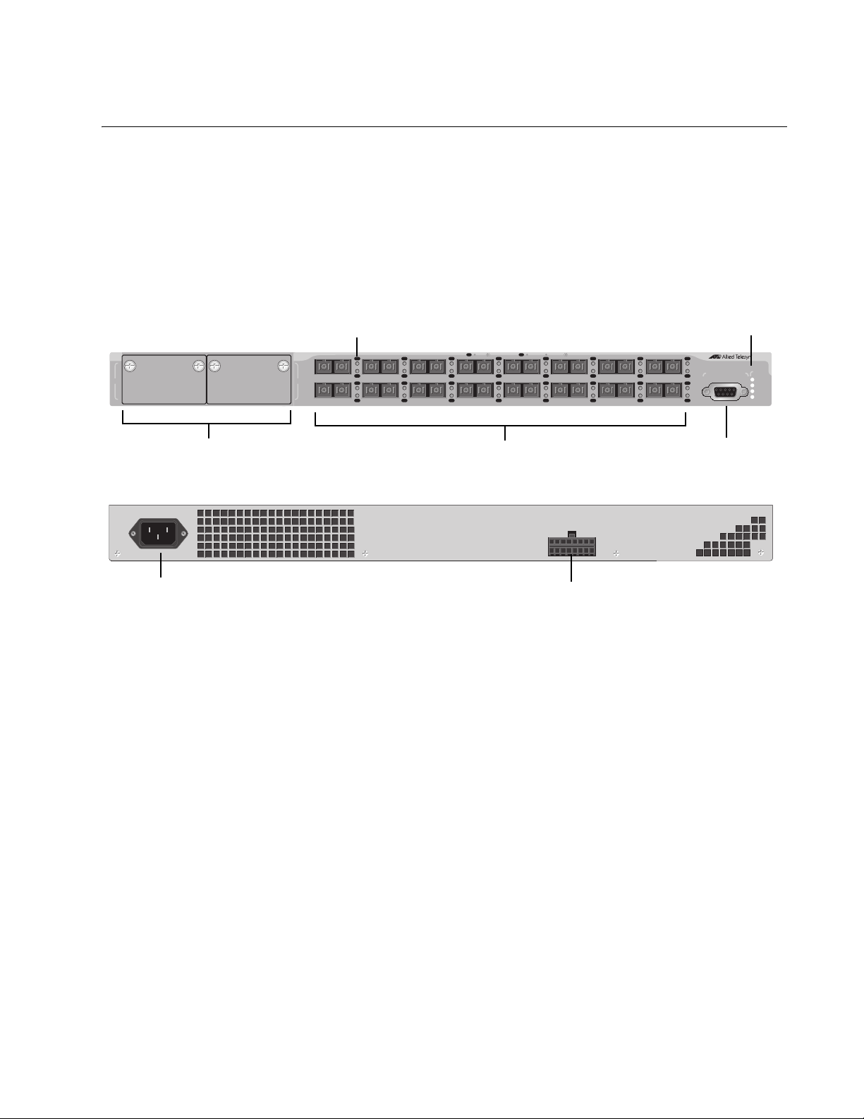
Module Expansion Slots
100Base-FX Ports
Terminal Port
System LEDs
Port LEDs
RPS Connector
AC Power Connector
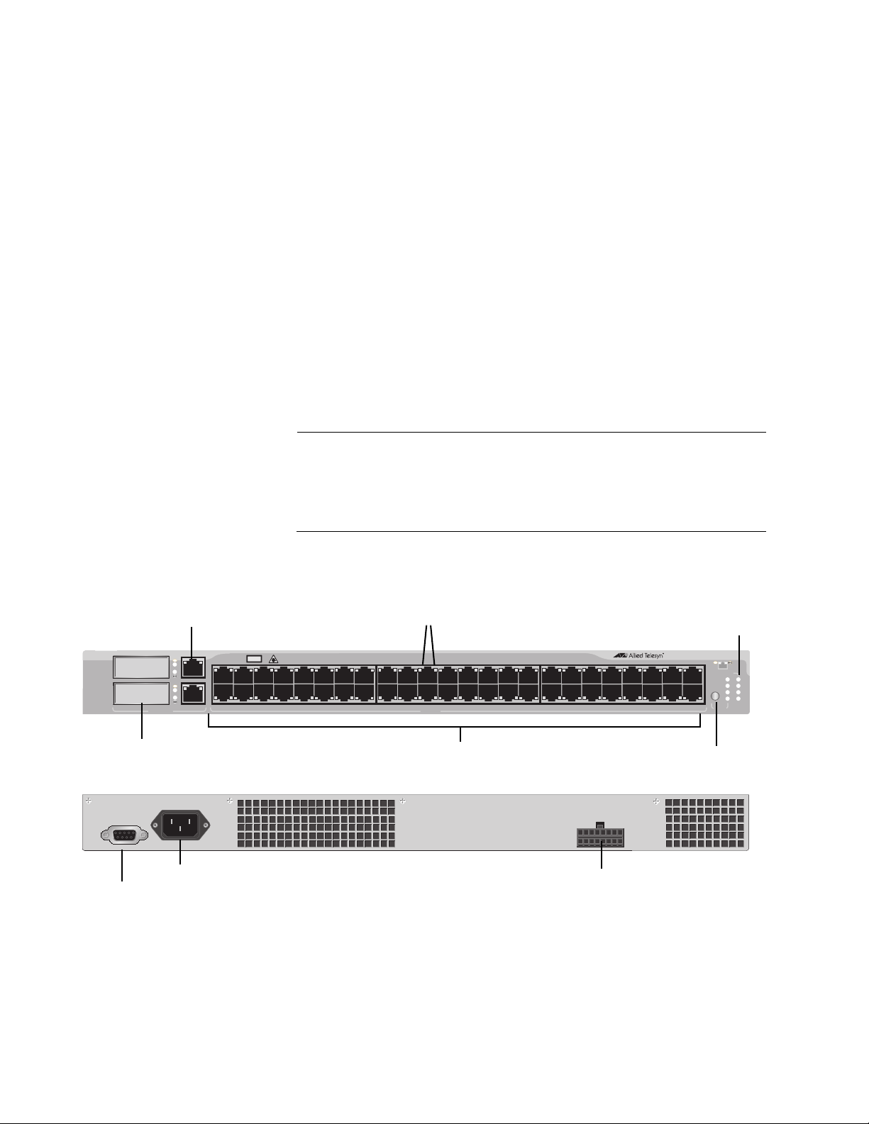
Model Descriptions
AT-8516F/SC The AT-8516F/SC switch has 16 100Base-FX fiber optic ports with dual
SC connectors. The ports operate at 100 Mbps, half- or full-duplex mode,
and have a maximum operating distance of 2 kilometers (1.24 miles) or
412 meters (1,360 feet), depending on the duplex mode, using 50/125 or
62.5/125 micron (core/cladding) multimode fiber optic cable.
Figure 1 illustrates the front panel of the AT-8516F/SC switch.
100-240VAC
~
RPS INPUT
Figure 1. AT-8516F/SC Switch Front and Back Panels
17
Page 18
Chapter 1: Overview
1 3 5 7 9 11 13 15 17 19 21 23
2 4 6 8 10 12 14 16 18 20 22 24
LINK
MODE
LINK
MODE
COL
100
FULL
ACT
FAULT
RPS
MASTER
PWR
MODE
1357 911
2
4
6
8
10 12
13 15 17
19 21 23
14
16
18 20 22 24
STATUS
2625
AT-8524M
Fast Ethernet Switch
10/100Base-TX Ports
Port Status
LED Mode
Select Button
System
LEDs
LEDs
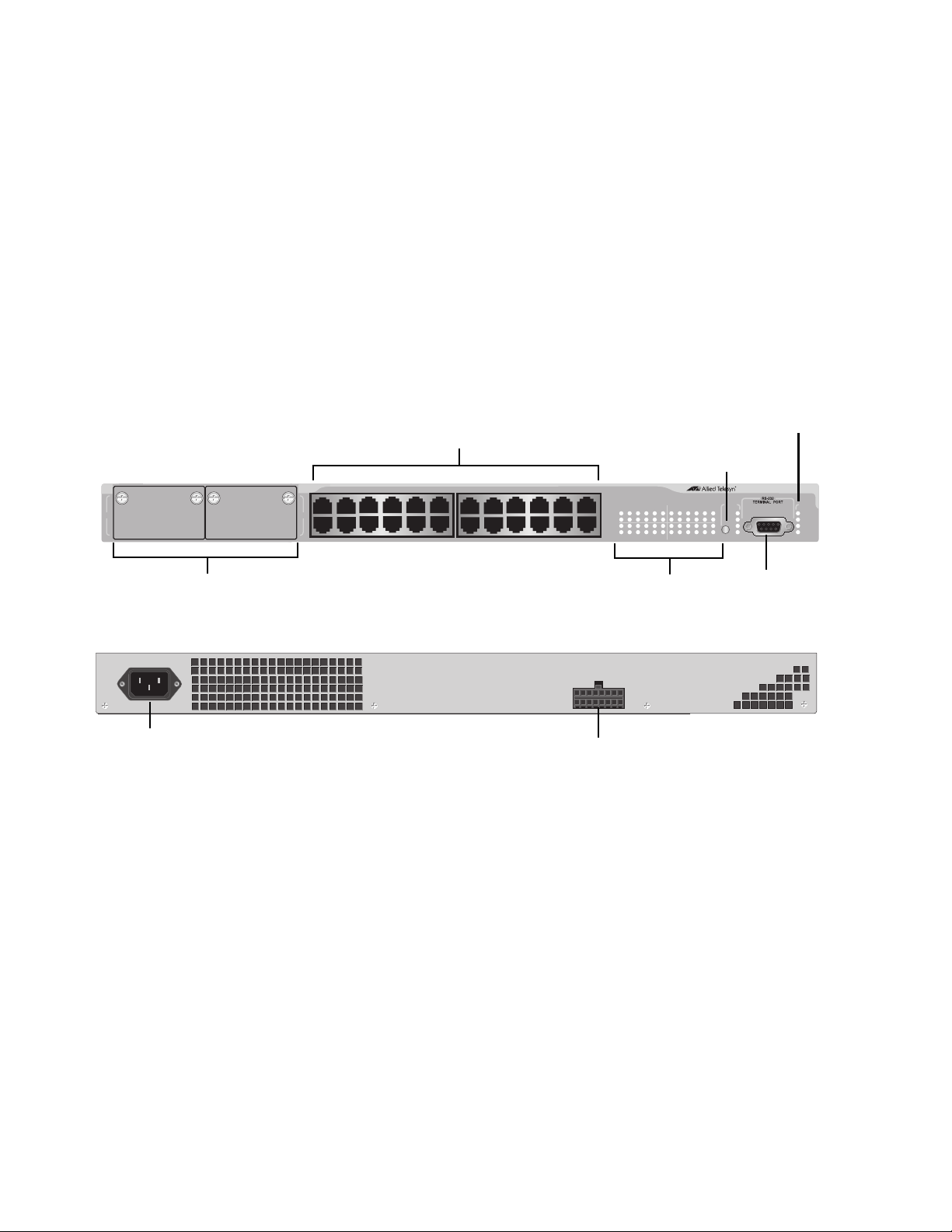
Module Expansion Slots
RS-232
Terminal Port
AC Power Connector
RPS Connector
AT-8524M The AT-8524M switch has 24 10/100Base-TX twisted pair ports and two
module expansion slots. The twisted pair ports feature RJ-45 connectors
and have a maximum operating distance of 100 meters (328 feet) using
Category 3 or better 100 ohm twisted pair cable for 10Base-T operation
and Category 5 or 5E 100 ohm twisted pair cable for 100Base-TX
operation.
The expansion slots are compatible with 100Base and 1000Base fiber
optic and twisted pair port expansion modules and the AT-STACKM
stacking module.
Figure 2 shows the front and back panels of the AT-8524M switch.
~
100-240VAC
Figure 2. AT-8524M Switch Front and Back Panels
RPS INPUT
18
Page 19
AT-8500 Series Layer 2+ Fast Ethernet Switches Installation Guide
10/100Base-TX Ports
100-240VAC
~
RPS INPUT
RPS INPUT VDC A Max
48V
12V
3.3V
8.5A
3A
15A
with PoE
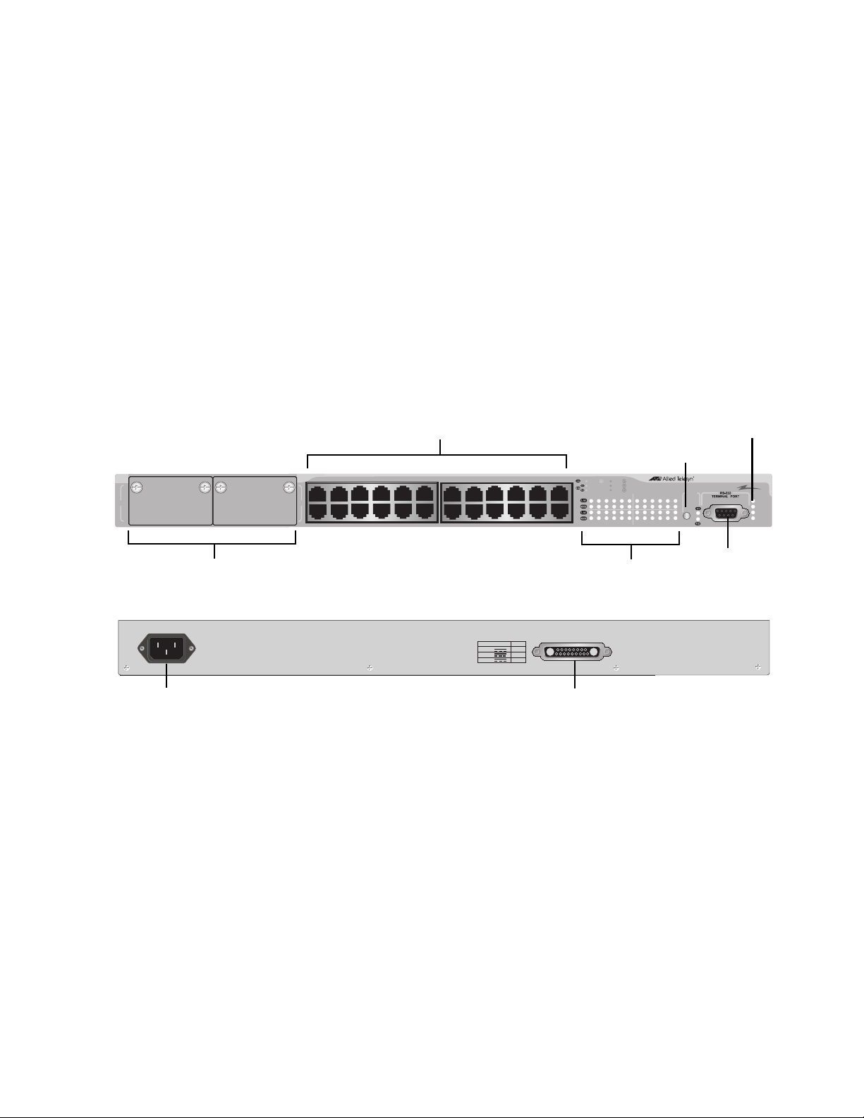
Module Expansion Slots
Port Status
LEDs
LED Mode
Select Button
System
LEDs
RS-232
Terminal Port
AC Power Connector
RPS Connector
AT-8524POE The AT-8524POE switch has 24 10/100Base-TX ports with Power over
Ethernet (PoE) capability. (For a description of this feature, refer to “Power
Over Ethernet” on page 27.) The ports feature RJ-45 connectors and have
a maximum operating distance of 100 meters (328 feet) using twisted pair
cable. The ports, when not using PoE, can use Category 3 or better 100
ohm twisted pair cable for 10Base-T operation and Category 5 or 5E 100
ohm twisted pair cable for 100Base-TX operation. For ports using PoE,
Category 5 or 5E 100 ohm twisted pair cable is required for both 10 and
100 Mbps operation.
The switch also features two expansion slots that are compatible with
100Base and 1000Base fiber optic and twisted pair port expansion
modules and the AT-STACKM stacking module.
Figure 3 shows the front and back panels of the AT-8524POE switch.
AT-8524POE
1357 911
25
26
2
4
8
6
10 12
13 15 17
14
16
19 21 23
18 20 22 24
10 LINK ACT
100 LINK ACT
FDX
HDX
COL
PD ON MAX CURRENTPD ERR
1 3 5 7 9 11 13 15 17 19 21 23
2 4 6 8 10 12 14 16 18 20 22 24
MODE
Fast Ethernet Switch
PoE
STATUS
FAULT
MASTER
RPS
PWR
Figure 3. AT-8524POE Switch Front and Back Panels
19
Page 20
Chapter 1: Overview
Note
COL
SPD
FDX
ACT
FLT
RPS
MSTR
PWR
STATUS
AT-8550GB
Fast Ethernet Switch
LINK
LINK
LINK
MAIN PORTS
13579
11 13 15 17 19 21 23 25 27 29 31 33 35 37 39 41 43 45 47
2 4 6 8 10 12 14 16 18 20 22 24 26 28 30 32 34 36 38 40 42 44 46 48
MODELINK 49R
49
50
GBIC
UPLINK PORTS
CLASS 1
LASER PRODUCT
MODE
MODELINK 50R
10/100Base-TX Ports
Port LEDs
10/100/1000Base-T Ports
GBIC Slots
100-240VAC
~
RPS INPUT
RS-232
Terminal Port
AC Power Connector
RPS Connector
LED Mode
Select Button
System
LEDs
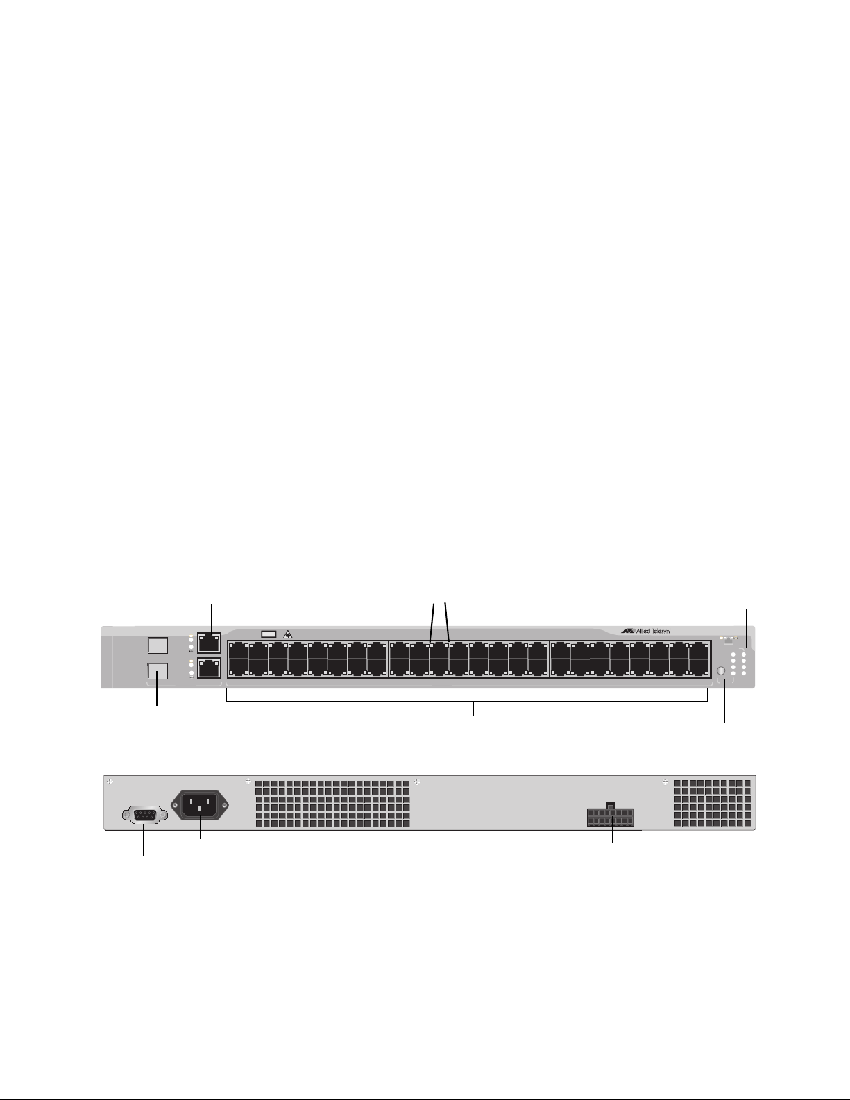
AT-8550GB The AT-8550GB switch has 48 10/100Base-TX twisted pair ports, capable
of operating at either 10 or 100 Mbps, with RJ-45 connectors. These ports
have a maximum operating distance of 100 meters (328 feet) using
Category 3 or better 100 ohm twisted pair cable for 10Base-T operation
and Category 5 or 5E 100 ohm twisted pair cable for 100Base-TX
operation.
The switch has two 10/100/1000Base-T twisted pair ports, labelled Ports
49R and 50R. They have RJ-45 connectors, require Category 5 or 5E 100
ohm twisted pair cable, and have a maximum operating distance of 100
meters (328 feet).
The switch also has two slots for two Gigabit Interface Converters
(GBICs). You can use the GBICs to add 1000Base-X fiber optic ports to
the switch to extend the distance of your network. For a list of GBICs
supported by the switch, contact your Allied Telesis sales representative
or refer to the Allied Telesis web site: www.alliedtelesis.com.
The twisted pair ports 49R and 50R change to a redundant status
when GBICs are installed and establish links with their end nodes. A
link on a GBIC port always takes precedence over that of the
corresponding 10/100/1000Base-T twisted pair port.
Figure 4 shows the front and back panels of the AT-8550GB switch.
Figure 4. AT-8550GB Switch Front and Back Panels
20
Page 21
AT-8500 Series Layer 2+ Fast Ethernet Switches Installation Guide
Note
COL
SPD
FDX
ACT
FLT
RPS
MSTR
PWR
STATUS
AT-8550SP
Fast Ethernet Switch
LINK
LINK
LINK
MAIN PORTS
13579
11 13 15 17 19 21 23 25 27 29 31 33 35 37 39 41 43 45 47
2 4 6 8 10 12 14 16 18 20 22 24 26 28 30 32 34 36 38 40 42 44 46 48
MODELINK 49R
49
50
SFP
UPLINK PORTS
CLASS 1
LASER PRODUCT
MODE
MODELINK 50R
Port LEDs
SFP Slots
RS-232
Terminal Port
AC Power Connector
RPS Connector
10/100Base-TX Ports
LED Mode
Select Button
System
LEDs
10/100/1000Base-T Ports
AT-8550SP The AT-8550SP switch has 48 10/100Base-TX twisted pair ports with
RJ-45 connectors. The ports have a maximum operating distance of 100
meters (328 feet) using Category 3 or better 100 ohm twisted pair cable for
10Base-T operation and Category 5 or 5E 100 ohm twisted pair cable for
100Base-TX operation.
The switch also features two 10/100/1000Base-T twisted pair ports,
labelled Ports 49R and 50R. They have RJ-45 connectors, require
Category 5 or 5E 100 ohm twisted pair cable, and have a maximum
operating distance of 100 meters (328 feet).
There are also two slots for two Small Form-factor Pluggable (SFP)
transceivers. You can use the slots to add 1000Base-X fiber optic ports to
the switch. For a list of supported SFP transceivers, contact your Allied
Telesis sales representative or refer to the Allied Telesis web site:
www.alliedtelesis.com.
The twisted pair ports 49R and 50R change to a redundant status
when SFP transceivers are installed and establish links with their
end nodes. A link on an SFP port always takes precedence over that
of the corresponding 10/100/1000Base-T twisted pair port.
100-240VAC
Figure 5 shows the front and back panels of the AT-8550GB switch.
~
Figure 5. AT-8550SP Switch Front and Back Panels
RPS INPUT
21
Page 22

Chapter 1: Overview
Note
Port Descriptions
This section provides information on the following port types found on the
AT-8500 Series switches:
“10/100Base-TX Twisted Pair Ports,” next
“10/100/1000Base-T Twisted Pair Ports” on page 24
“100Base-FX Fiber Optic Ports” on page 25
10/100Base-TX
Twisted Pair
Ports
This section applies to the AT-8524M, AT-8524POE, AT-8550GB, and
AT-8550SP switches.
Type of Connector
The 10/100Base-TX twisted pair ports feature 8-pin RJ-45 connectors.
Only four of the pins are used when a port is operating at 10 or 100 Mbps
Speed
The twisted pair ports are 10/100Base-TX compliant and are capable of
10 megabits per second (Mbps) or 100 Mbps speeds. You can set the port
speed manually or, because the ports are IEEE 802.3u Auto-Negotiation
compliant, you can let the switch set each port’s speed automatically. With
Auto-Negotiation, the switch automatically matches the highest possible
common speed between each switch port and each end node. For
example, if an end node is capable of only 10 Mbps, the switch sets the
port connected to the end node to 10 Mbps.
Auto-Negotiation is activated as the default on all twisted pair ports
on the switch. To deactivate Auto-Negotiation and set the speeds
manually, refer to the AT-S62 Management Software User’s Guides.
Duplex Mode
Each twisted pair port on the switch can operate in either half- or fullduplex mode. The twisted pair ports are IEEE 802.3u-compliant and will
Auto-Negotiate the duplex mode setting.
If desired, you can disable Auto-Negotiation on one or all of the switch
ports so that you can set the duplex mode manually through the switch’s
management software.
22
Page 23

AT-8500 Series Layer 2+ Fast Ethernet Switches Installation Guide
Note
Note
In order for a switch port to successfully Auto-Negotiate its duplex
mode with an end node, the end node should also be using AutoNegotiation. Otherwise, a duplex mode mismatch can occur. A
switch port using Auto-Negotiation will default to half-duplex if it
detects that the end node is not using Auto-Negotiation. This will
result in a mismatch if the end node is operating at a fixed duplex
mode of full-duplex.
To avoid this problem, when you connect an end node with a fixed
duplex mode of full-duplex to a switch port, you should use the
AT-S62 management software to disable Auto-Negotiation on the
port and set the port speed and duplex mode manually.
Maximum Distance
Each twisted pair port has a maximum operating distance of 100 meters
(328 feet).
Type of Cabling
For 10 Mbps operation, Category 3 or better 100 ohm shielded or
unshielded twisted pair cabling is required. For 100 Mbps operation,
Category 5 or Enhanced Category 5 (5E) 100 ohm shielded or unshielded
twisted pair cabling is required.
Auto-MDI/MDI-X
The twisted pair ports are auto-MDI/MDI-X. They automatically configure
themselves as either MDI or MDI-X, depending on the configuration of the
port on the end node. This feature allows you to use either straight-through
or crossover twisted pair cables to connect devices to the ports.
The auto-MDI/MDI-X feature on a port is available only when the
port is set to Auto-Negotiation. If you disable Auto-Negotiation and
set a port’s speed and duplex mode manually, the port defaults to
MDI-X. For instructions on configuring a port, refer to the AT-S62
Management Software User’s Guides.
Port Pinouts
For the port pinouts for the AT-8524M, AT-8550GB, and AT-8550SP
switches, refer to Table 12 on page 83. For the port pinouts for the
AT-8524POE switch, refer to Table 13 on page 83.
23
Page 24

Chapter 1: Overview
Note
Note
10/100/
1000Base-T
Twisted Pair
Ports
This section applies to Port 49R and Port 50R on the AT-8550GB and
AT-8550SP switches.
Type of Connector
The ports have 8-pin RJ-45 connectors. The ports use four pins when
operating at 10 or 100 Mbps and all eight pins when operating at
1000 Mbps.
Speed
The ports can operate at 10, 100, or 1000 Mbps. The speed is set
automatically through Auto-Negotiation or you can set the speed to 10 or
100 Mbps manually through the management software.
Ports 49R and 50R can operate at 1000 Mbps only when set to
Auto-Negotiation. You cannot manually set these ports to 1000
Mbps.
Duplex Mode
The ports can operate in either half- or full-duplex mode. The ports are
IEEE 802.3u compliant and will Auto-Negotiate the duplex mode. If
needed, Auto-Negotiation can be disabled so that you can set the duplex
mode manually through the management software.
In order for a 10/100/1000Base-T port to successfully AutoNegotiate its duplex mode with an end node, the end node should
also be using Auto-Negotiation. Otherwise, a duplex mode
mismatch can occur. A port, using Auto-Negotiation, will default to
half-duplex if it detects that the end node is not using AutoNegotiation. This will result in a mismatch if the end node is
operating at a fixed duplex mode of full-duplex.
To avoid this problem, when you connect an end node with a fixed
duplex mode of full-duplex to a 10/100/1000Base-T port, you should
use the AT-S62 management software to disable Auto-Negotiation
on the port and set the port speed and duplex mode manually.
Maximum Distance
The ports have a maximum operating distance of 100 meters (328 feet).
Type of Cable
24
Page 25

AT-8500 Series Layer 2+ Fast Ethernet Switches Installation Guide
Note
For 10 Mbps, the port requires Category 3 or better 100 ohm shielded or
unshielded twisted pair cabling. For 100 or 1000 Mbps operation, the ports
require Category 5 or Enhanced Category 5 (5E) 100 ohm shielded or
unshielded twisted pair cabling.
Auto-MDI/MDI-X
The ports are auto-MDI/MDI-X. They automatically configure themselves
as either MDI or MDI-X. This feature allows you to use a straight-through
twisted pair cable to connect any type of device to a port.
The auto-MDI/MDI-X feature on a 10/100/1000Base-T port is
functional only when the port is set to Auto-Negotiation. If you
disable Auto-Negotiation and set the port’s speed and duplex mode
manually, the port defaults to MDI-X. For instructions on configuring
a port, refer to the AT-S62 Management Software User’s Guides.
100Base-FX
Fiber Optic Ports
Port Pinouts
For the pinouts of these ports when operating at 10 or 100 Mbps, refer to
Table 12 on page 83. For port pinouts when the ports are operating at
1000 Mbps, refer to Table 14 on page 84.
This section applies to the AT-8516F/SC switch.
Type of Connector
The fiber optic ports on the AT-8516F/SC switch have dual SC connectors.
Speed
The fiber optic ports have a fixed operating speed of 100 megabits per
second (Mbps). The speed cannot be changed.
Duplex Mode
The fiber optic ports can operate in either half- or full-duplex mode. You
can set the duplex mode manually or allow the switch to set it
automatically through Auto-Negotiation.
Maximum Distance
Each fiber optic port has a maximum operating distance of two kilometers
(1.25 miles) when operating in full-duplex mode and 412 meters (1,360
feet) when operating in half-duplex mode.
25
Page 26

Chapter 1: Overview
Note
Type of Cable
The fiber optic ports can use either 50/125 or 62.5/125 micron multimode
fiber optic cable.
Do not use single-mode fiber optic cable with these ports.
26
Page 27

Power Over Ethernet
The following discussion applies only to the AT-8524POE switch.
The twisted pair ports on the AT-8524POE switch feature Power over
Ethernet (PoE). PoE is a mechanism for supplying power to network
devices over the same twisted pair cables used to carry network traffic.
This feature can simplify network installation and maintenance by allowing
you to use the switch as a central power source for other network devices.
A device that receives its power over an Ethernet cable is called a
powered device. Examples of such devices can be wireless access points,
IP telephones, web cams, and even other Ethernet switches. A powered
device connected to a port on the switch will receive both network traffic
and power over the same twisted pair cable.
There are several advantages that the PoE feature of the AT-8524POE
switch adds to the installation and maintenance of your network. First,
because the switch acts as the central power source for your powered
devices, adding an uninterruptible power source (UPS) to the switch
increases the protection not just to the switch itself from possible power
source problems but also to all of the powered devices connected to it.
This can increase the reliability of your network by minimizing the impact
to network operations from a power failure.
AT-8500 Series Layer 2+ Fast Ethernet Switches Installation Guide
PoE can also simplify the installation of your network. A frequent issue in
selecting a location for a network device is whether there is a power
source nearby. This often limits equipment placement or requires the
added cost and time of having additional electrical sources installed. With
PoE, you can install PoE-compatible network equipment wherever they
are needed without having to worry about whether they are near a power
source.
The switch automatically determines whether or not a device connected to
a port is a powered device. A powered device has a signature resistor or
signature capacitor that the switch can detect over the Ethernet cabling. If
the resistor or capacitor is present, the switch assumes that the device is a
powered device.
Power Budgeting The AT-8524POE Layer 2+ Fast Ethernet Switch provides a maximum of
15.4 W of power per port on all 24 ports for a total power consumption of
370 W, while at the same time furnishing standard 10/100 Mbps Ethernet
functionality.
The AT-8524POE smart power management functionality supports any
combination of Ethernet ports (1-24) that supply power for IEEE 802.3af
Class 0, 1, 2, or 3 powered devices up to a maximum of 370 watts, as
27
Page 28

Chapter 1: Overview
described in Table 3. .
Table 3. IEEE 802.3af Class vs. Power Levels
Class Usage
Minimum Power
Levels Output at
the PSE
Maximum Power
Levels Output at
the PD
0 Default 15.4W 0.44W to 12.95W
1 Optional 4.0W 0.44W to 3.84W
2 Optional 7.0W 3.84W to 6.49W
3 Optional 15.4W 6.49W to 12.95W
A port connected to a network node that is not a powered device (that is, a
device that receives its power from another power source) functions as a
regular Ethernet port, without PoE. The PoE feature remains enabled on
the port but no power is delivered to the device.
Implementation A standard Ethernet twisted pair cable contains four pairs of strands for a
total of eight strands. 10/100 Mbps network traffic requires only four
strands (1, 2, 3, and 6), leaving four strands in the cable unused (4, 5, 7,
and 8).
The PoE standard, IEEE 802.3af, describes two alternative ways for
delivering power to a powered device (PD) over twisted pair cabling.
Alternative A uses the same strands that carry the network traffic.
Alternative B uses the spare strands. The PoE implementation on the AT8524POE Layer 2+ Fast Ethernet Switch is Alternative A, where power is
transmitted over strands 1, 2, 3, and 6.
28
PD’s that comply with the IEEE 802.3af standard typically support both
power delivery methods. So long as a PD is compliant with the standard, it
should be able to receive its power from the switch while using either a
straight or cross-over cable. The PoE feature on the AT-8524POE Layer
2+ Fast Ethernet Switch should also work with most legacy PD’s as long
as the device can be powered on pins 1, 2, 3, and 6. A legacy device is a
node that was manufactured before the IEEE 802.3af standard was
completed and, consequently, may not adhere to the standard. If this is
the case, a straight (MDI) cable may be needed to insure that the DC
polarity is correct.
Page 29

GBIC and SFP Slots
482
The AT-8550GB switch has two GBIC slots, and AT-8550SP switch has
two SFP slots. The slots are labelled Port 49 and Port 50. Each slot can
accommodate one optional fiber optic Gigabit Interface Converter (GBIC)
or Small Form-factor Pluggable (SPF) transceiver.
These modules are a fast and easy way for you to add an 1000 Mbps fiber
optic port to your Fast Ethernet switch. You can use the modules to extend
the distance of your network, build a high-speed backbone network
between switches, or connect additional end nodes to the network, such
as high-speed servers.
Figure 6 shows an example of a fiber optic GBIC, and Figure 7 shows an
SFP transceiver.
AT-8500 Series Layer 2+ Fast Ethernet Switches Installation Guide
Figure 6. GBIC Module
Figure 7. SFP Transceiver
When you install a GBIC or SFP in Port 49 or Port 50 and the module
establishes a link with its end node, the corresponding twisted pair port,
Port 49R or 50R, changes to a redundant status. A link on a GBIC or SFP
port always takes precedence over that of the corresponding 10/100/
1000Base-T twisted pair port.
For a list of the GBIC and SFP modules supported by the
AT-8550GB and AT-8550SP switches, contact your Allied Telesis
sales representative or refer to our web site at:
www.alliedtelesis.com.
29
Page 30

Chapter 1: Overview
Note
Module Expansion Slots
The AT-8516F/SC, AT-8524M, and AT-8524POE switches have two
expansion slots. Each slot can accommodate an expansion module. You
can use the slots to add 100Base and 1000Base fiber optic and twisted
pair ports to the switch.
For a list of the Allied Telesis expansion modules supported by the
switches, contact your Allied Telesis sales representative or refer to
our web site at: www.alliedtelesis.com.
30
Page 31

LEDs
Note
AT-8500 Series Layer 2+ Fast Ethernet Switches Installation Guide
This section provides information on the LEDs found on the AT-8500
Series switches:
“Twisted Pair Port LEDs and the LED Mode Select Button,” next
“Fiber Optic Port LEDs” on page 34
“GBIC and SFP Expansion Slot LEDs” on page 35
“System LEDs” on page 36
Twisted Pair Port
LEDs and the
LED Mode Select
Button
This section applies to the AT-8524M, AT-8524POE, AT-8550GB, and
AT-8550SP switches.
The port LEDs on the front panel display port status information. Each port
has two LEDs. One of the LEDs displays the status of the link between a
port and its end node. The second LED, labeled MODE, displays a variety
of status information, depending on the switch model. You use the Mode
Select button on the front panel to toggle the Mode LEDs to display
different status information. The LEDs next to the Mode Select button
indicate the status being displayed by the port Mode LEDs.
Toggling the Mode Selection button does not affect the normal
operations of the switch.
Table 4 describes the LEDs for the 10/100Base-TX twisted pair ports on
the AT-8524M, AT-8550GB, and AT-8550SP switches.
Table 4. LEDs for the 10/100Base-TX Twisted Pair Ports on the
AT-8524M, AT-8550GB, and AT-8550SP Switches
LED State Description
LINK OFF Indicates that there is no link between the
port and the end node.
Green Indicates a valid link has been established
between the port and the end node.
Mode - COL OFF Indicates that no data collisions are
occurring on the port.
Flashing
Green
Indicates that data collisions are occurring
on the port.
31
Page 32

Chapter 1: Overview
Table 4. LEDs for the 10/100Base-TX Twisted Pair Ports on the
AT-8524M, AT-8550GB, and AT-8550SP Switches (Continued)
LED State Description
Mode - 100
(AT-8524M)
OFF Indicates that the port is operating at 10
Mbps.
Green Indicates that the port is operating at 100
Mbps.
Mode - SPD
(AT-8550GB
and
AT-8550SP)
Mode - FULL
(AT-8524M)
OFF Indicates that the port is operating at 10
Mbps.
Green Indicates that the port is operating at 100
Mbps.
OFF Indicates that the port is operating in half-
duplex mode.
Green Indicates that the port is operating in full-
duplex mode.
MODE - FDX
AT-8550GB
and
AT-8550SP)
OFF Indicates that the port is operating in half-
duplex mode.
Green Indicates that the port is operating in full-
duplex mode.
Mode - ACT OFF Indicates that there is no activity on the port.
Flashing
Green
Indicates that the port is transmitting and/or
receiving data packets.
Table 5 describes the LEDs for the 10/100/1000Base-TX twisted pair
ports, Ports 49R and 50R, on the AT-8550GB and AT-8550SP switches.
Table 5. LEDs for Ports 49R and 50R on the AT-8550GB and AT-8550SP
Switches
LED State Description
LINK OFF Indicates that there is no link between the
port and the end node.
Green Indicates a valid link has been established
between the port and the end node.
Mode - COL OFF Indicates that no data collisions are occurring
on the port.
Flashing
Green
Indicates that data collisions are occurring on
the port.
32
Page 33

AT-8500 Series Layer 2+ Fast Ethernet Switches Installation Guide
Table 5. LEDs for Ports 49R and 50R on the AT-8550GB and AT-8550SP
Switches (Continued)
LED State Description
Mode - SPD OFF Indicates that the port is operating at 10 or
100 Mbps.
Green Indicates that the port is operating at 1000
Mbps.
Mode - FDX OFF Indicates that the port is operating in half-
duplex mode.
Green Indicates that the port is operating in full-
duplex mode.
Mode - ACT OFF Indicates that there is no activity on the port.
Flashing
Green
Indicates that the port is transmitting and/or
receiving data packets.
Table 6 describes the LEDs for the 10/100Base-TX twisted pair ports on
the AT-8524POE switch.
Table 6. LEDs for the 10/100Base-TX Twisted Pair Ports on the
AT-8524POE Switch
LED State Description
L/A OFF Indicates that the port has not established a
link with its end node.
Steady
Green
Flashing
Green
Steady
Amber
Flashing
Amber
Indicates the port has established a valid
100 Mbps link with its end node.
Indicates the port is receiving or transmitting
packets at 100 Mbps.
Indicates the port has established a valid 10
Mbps link with its end node.
Indicates the port is receiving or transmitting
packets at 10 Mbps.
33
Page 34

Chapter 1: Overview
Table 6. LEDs for the 10/100Base-TX Twisted Pair Ports on the
AT-8524POE Switch (Continued)
LED State Description
Mode - DC OFF Indicates that the port has not established a
valid link with its end node.
Steady
Green
Steady
Amber
Flashing
Amber
Mode - POE OFF Indicates that the device connected to the
Green Indicates that the end node is a powered
Steady
Amber
Flashing
Amber
Indicates that the port is operating in full
duplex mode.
Indicates that the port is operating in half
duplex mode.
Indicates that the port is operating in half
duplex mode and that data collisions are
occurring on the port.
port is not a powered device and does not
require PoE.
device and that the port is providing power
to it.
Indicates that the port experienced a
problem providing PoE to the end node. For
further information, refer to Chapter 3,
“Troubleshooting” on page 77.
Indicates that the port is connected to a
powered device but that providing power to
it would exceed the maximum PoE power
budget of the switch. For further
information, refer to Chapter 3,
“Troubleshooting” on page 77.
Fiber Optic Port
LEDs
34
This section applies to the AT-8516F/SC switch. The fiber optic ports on
an AT-8516F/SC switch have two LEDs, labeled L/A and D/C. The LEDs
Page 35

AT-8500 Series Layer 2+ Fast Ethernet Switches Installation Guide
Note
are defined in Table 7.
Table 7. LEDs for the Fiber Optic Ports on the AT-8516F/SC Switch
LED State Description
L/A OFF Indicates no link has been established between
the port and the end node.
Green Indicates a valid link exists between the port
and the end node.
GBIC and SFP
Expansion Slot
LEDs
Flashing
Green
D/C Green Indicates that the port is operating in full-duplex
Amber Indicates that the port is operating in half-duplex
Flashing
Amber
The AT-8516F/SC switch does not have an LED Mode Select
button.
The GBIC and SFP slots on the AT-8550GB and AT-8550SP switches,
respectively, have two LEDs. The LEDs display the operating status of the
fiber optic port. Use the Mode Select button on the switch to toggle the
status information displayed by the MODE LED. The LEDs are defined in
Table 8.
Indicates that the port is transmitting and/or
receiving data packets.
mode.
mode.
Indicates that data collisions are occurring on
the port.
Table 8. LEDs for the Optional GBIC and SFP Ports on an AT-8550GB and
AT-8550SP Switches
LED State Description
LINK OFF Indicates that there is no link between the
port and the end node.
Solid
Green
Mode - COL OFF Indicates that no data collisions are
Flashing
Green
Indicates a valid link has been established
between the port and the end node.
occurring on the port.
Indicates that data collisions are occurring
on the port.
35
Page 36

Chapter 1: Overview
Table 8. LEDs for the Optional GBIC and SFP Ports on an AT-8550GB and
AT-8550SP Switches
LED State Description
Mode - SPD Solid
Green
Indicates that the port is operating at 1000
Mbps.
Mode - FDX OFF Indicates that the port is operating in
half-duplex mode.
Solid
Green
Indicates that the port is operating in
full-duplex mode.
Mode - ACT OFF Indicates that there is no activity on the port.
Flashing
Green
Indicates that the port is transmitting and/or
receiving data packets.
System LEDs The system LEDs on the front panel display general status information, as
described in Table 9.
Table 9. System LEDs
LED State Description
FAULT
or FLT
OFF Indicates normal operation.
Red Indicates that the management software is
saving a change to its configuration. The LED
goes off once the configuration has been
saved.
36
If the FAULT LED remains on, the switch or
management software may have experienced a
malfunction. Refer to Chapter 3,
“Troubleshooting” on page 77 for instructions
on how to troubleshoot a problem.
MASTE
R or
Green Indicates that the switch is functioning as the
master switch of an enhanced stack.
MSTR
OFF Indicates that the switch is a slave switch or is
not a member of a stack.
RPS Green Indicates that an optional redundant power
supply is connected to the switch.
OFF Indicates that there is no optional redundant
power supply connected to the switch.
PWR Green Indicates that the switch is receiving power.
Page 37

RS-232 Terminal Port
Note
Note
You can use the RS-232 terminal port to establish a local (out-of-band)
management session with the switch and to configure the switch’s
operating parameters. You establish a local management session with the
switch by connecting either a terminal or a personal computer with a
terminal emulation program to the port.
The RS-232 terminal port has a DB-9 female connector and uses a
straight-through RS-232 cable (included with the switch). The default
settings for the RS-232 terminal port are:
AT-8500 Series Layer 2+ Fast Ethernet Switches Installation Guide
You are not required to manage an AT-8500 Series switch. If the
default switch settings are adequate for your network, you can use
the unit as an unmanaged switch. For the default settings, refer to
the AT-S62 Management Software User’s Guides.
Baud rate: 9600 bps
Data bits: 8
Parity: None
Stop bits: 1
Flow control: None
These settings are for a DEC VT100 or ANSI terminal, or an
equivalent terminal emulation program.
37
Page 38

Chapter 1: Overview
Note
Note
Power Options and Connectors
This section provides information about the power options and features on
the AT-8500 Series switches:
“RPS Connector,” next
“AC Power Connector” on page 39
“DC Power Connector” on page 39
RPS Connector The RPS connector on the back panel of the switch connects to an
optional AT-RPS3004 or AT-RPS3104 redundant power supply unit.
Figure 8 illustrates an AT-RPS3004 unit. A redundant power supply unit
can provide power to the switch in the event the switch’s internal power
supply should fail.
The AT-RPS3004 unit is used with the AT-8516F/SC, AT-8524M,
AT-8550GB, and AT-8550SP switches. The AT-RPS3104 unit is
used with the AT-8524POE switch. Do not use the AT-RPS3004 unit
with the AT-8524POE switch.
A redundant external power supply comes with one pre-installed power
module and has three empty slots for additional power modules. Each
power module can support one switch, making the unit capable of
supporting up to four switches simultaneously.
Figure 8. AT-RPS3004 Redundant Power Supply Unit
DC models of the AT-8500 Series switches do not feature an RPS
connector.
38
Page 39

AT-8500 Series Layer 2+ Fast Ethernet Switches Installation Guide
AC Power
Connector
DC Power
Connector
The switch has a single AC power supply socket on the back panel, which
has autoswitch AC inputs. To power the switch on or off, you connect or
disconnect the power cord.
Refer to Appendix A, “Technical Specifications” on page 81 for the input
voltage range.
Some models of the AT-8500 Series switch are offered with a DC terminal
block on the back panel instead of an AC socket, for those network
installations that require DC equipment. Refer to Appendix A, “Technical
Specifications” on page 81, for the input voltage range and “Wiring and
Powering on an DC Powered Unit” on page 70, for instructions on how to
wire a DC powered unit.
39
Page 40

Chapter 1: Overview
A Few Basics about Ethernet Switching
An Ethernet switch interconnects network devices, such as workstations,
printers, routers, and other Ethernet switches, so that they can
communicate with each other by sending and receiving Ethernet frames.
MAC Address
Table
Every hardware device in your network has a MAC address and each
MAC address is unique. The address is assigned to a device by the
device’s manufacturer. For example, the network interface cards that you
install in your computers have a unique MAC address assigned to them by
the adapter manufacturers.
An AT-8500 Series Fast Ethernet Switch has a MAC address table
capable of storing up to 8,000 MAC addresses. The switch uses the table
to store the MAC addresses of the network end nodes connected to the
ports, along with the port number on which each address was learned.
A switch learns the MAC addresses of the end nodes by examining the
source address of each packet received on a port. It adds the address and
port on which the packet was received to the MAC table if the address had
not already been entered in the table. The result is a table that contains all
the MAC addresses of the devices that are connected to the switch’s
ports, and the port number where each address was learned.
When the switch receives a packet, it also examines the destination
address and, by referring to its MAC address table, determines the port on
which the destination end node is connected. It then forwards the packet
to the appropriate port and on to the end node. This increases network
bandwidth by limiting each packet to the appropriate port when the
intended end node is located, freeing the other switch ports for receiving
and transmitting data.
If the switch receives a packet with a destination address that is not in the
MAC address table, it floods the packet to all the ports on the switch. If the
ports have been grouped into virtual LANs, the switch floods the packet
only to those ports which belong to the same VLAN as the port on which
the packet was received. This prevents packets from being forwarded into
inappropriate LAN segments, increasing network security. When the
destination an end node responds, the switch adds its MAC address and
port number to the table.
If the switch receives a packet with a destination address that is on the
same port on which the packet was received, it discards the packet
without forwarding it on to any port. Because both the source end node
and the destination end node for the packet are located on the same port
on the switch, there is no reason for the switch to forward the packet.
Duplex Mode Duplex mode refers to the manner in which an end node receives and
40
Page 41

AT-8500 Series Layer 2+ Fast Ethernet Switches Installation Guide
Note
transmits data. If an end node can receive or transmit data, but not both
simultaneously, the end node is operating in what is referred to as halfduplex mode. If an end node can both receive and transmit data
simultaneously, the end node is said to be operating in full-duplex mode.
Naturally, an end node capable of operating in full-duplex can handle data
much faster than an end node that can only operate in half-duplex mode.
The twisted pair ports on the AT-8500 Series switches can operate in
either half- or full-duplex mode. The twisted pair ports are IEEE 802.3ucompliant and will Auto-Negotiate the duplex mode setting for you.
By allowing the switch to configure the duplex mode for each port, you will
not need to change the setting for a port on the switch should you replace
an end node with an end node that has a different duplex mode capability.
With Auto-Negotiation, the switch automatically resets the port to a new
duplex mode setting.
If desired, you can disable Auto-Negotiation on the switch ports so that
you can set the duplex mode manually through the switch’s management
software.
Store and
Forward
In order for a switch port to successfully Auto-Negotiate its duplex
mode with an end node, the end node should also be using AutoNegotiation. Otherwise, a duplex mode mismatch can occur. A
switch port, using Auto-Negotiation, defaults to half-duplex if it
detects that the end node is not using Auto-Negotiation. This results
in a mismatch if the end node is operating at a fixed duplex mode of
full-duplex.
Consequently, when you connect an end node with a fixed duplex
mode of full-duplex to a switch port, you should use the AT-S62
management software to disable Auto-Negotiation on the port and
set the port speed and duplex mode manually.
These Fast Ethernet switches use store and forward as the method for
receiving and transmitting frames. When an Ethernet frame is received on
a switch port, the switch does not retransmit the frame out the destination
port until it has received the entire frame and stored the frame in a port
buffer. It then examines the frame to determine if it is a valid frame. Invalid
frames, such as fragments or runts, are discarded by the switch. This
ensures that only valid frames are transmitted out the switch ports and that
damaged frames are not propagated on your network.
Back Pressure
and Flow Control
To maintain the orderly movement of data between the end nodes, an
Ethernet switch may periodically need to signal an end node to stop
sending data.
41
Page 42

Chapter 1: Overview
How a switch signals an end node to stop transmitting data differs
depending on the speed and duplex mode of the end node and switch
port. A twisted pair port operating at 100 Mbps port and half-duplex mode
stops an end node from transmitting data by forcing a collision. A collision
on an Ethernet network occurs when two end nodes attempt to transmit
data using the same data link at the same time. A collision causes end
nodes to stop sending data. When the switch needs to stop a 100 Mbps,
half-duplex end node from transmitting data, it forces a collision on the
data link, which stops the end node. After the switch is ready to receive
data again, the switch stops forcing collisions. This is referred to as back
pressure.
A port operating at 100 Mbps and full-duplex mode uses PAUSE frames,
as specified in the IEEE 802.3x standard, to stop the transmission of data
from an end node. Whenever the switch wants an end node to stop
transmitting data, it issues this frame. The frame instructs the end node to
cease transmission. The switch continues to issue PAUSE frames until it
is ready again to receive data from the end node. This is referred to as
flow control.
42
Page 43

Network Topologies
MODE
STATUS
AT-8524M
Fast Ethernet Switch
Legend
10 Mbps
100 Mbps
AT-8524M Fast
Ethernet Switch
This section illustrates several of the network topologies you can create
with the AT-8500 Series Fast Ethernet switch.
AT-8500 Series Layer 2+ Fast Ethernet Switches Installation Guide
Power
Workgroup
Topology
The topology shown in Figure 9 is commonly referred to as a power
workgroup topology. Each workstation or end node is connected directly to
a port on an AT-8524M Fast Ethernet Switch. This provides each end
node with a dedicated data link to the switch for best performance and
reliability. The devices can operate at either 10 Mbps or 100 Mbps.
Collapsed
Backbone
Topology
Figure 9. Power Workgroup Topology
In the topology illustrated in Figure 10, an AT-8524M Fast Ethernet Switch
connects together 10/100 Mbps Ethernet hubs. This type of topology is
often referred to as a collapsed backbone topology. The switch functions
as the focal point of the network by acting as a bridge between the
different workgroups. The switch transfers an Ethernet frame from hub to
hub only when the destination end node for the frame is on a different hub
than the end node that originated the frame. This reduces the amount of
unnecessary data traffic in each workgroup, freeing up bandwidth and
improving network performance.
43
Page 44

Chapter 1: Overview
Ethernet
Hubs
Legend
10 Mbps
100 Mbps
AT-8524M Fast
Ethernet Switch
Fast Ethernet Switch
AT-8524M
MODE
STATUS
8
7
6
5
4
3
2
1
4
3
2
1
8
7
6
5
3
2
1
7
6
5
4
Figure 10. Collapsed Backbone Topology
Mixed Topology You can always combine topologies as well as build a larger network by
connecting different switches together. If the switches are within 100
meters (328 feet) of each other, you can use the twisted pair ports. If the
switches are further apart, then you can use fiber optic ports.
8
44
Page 45
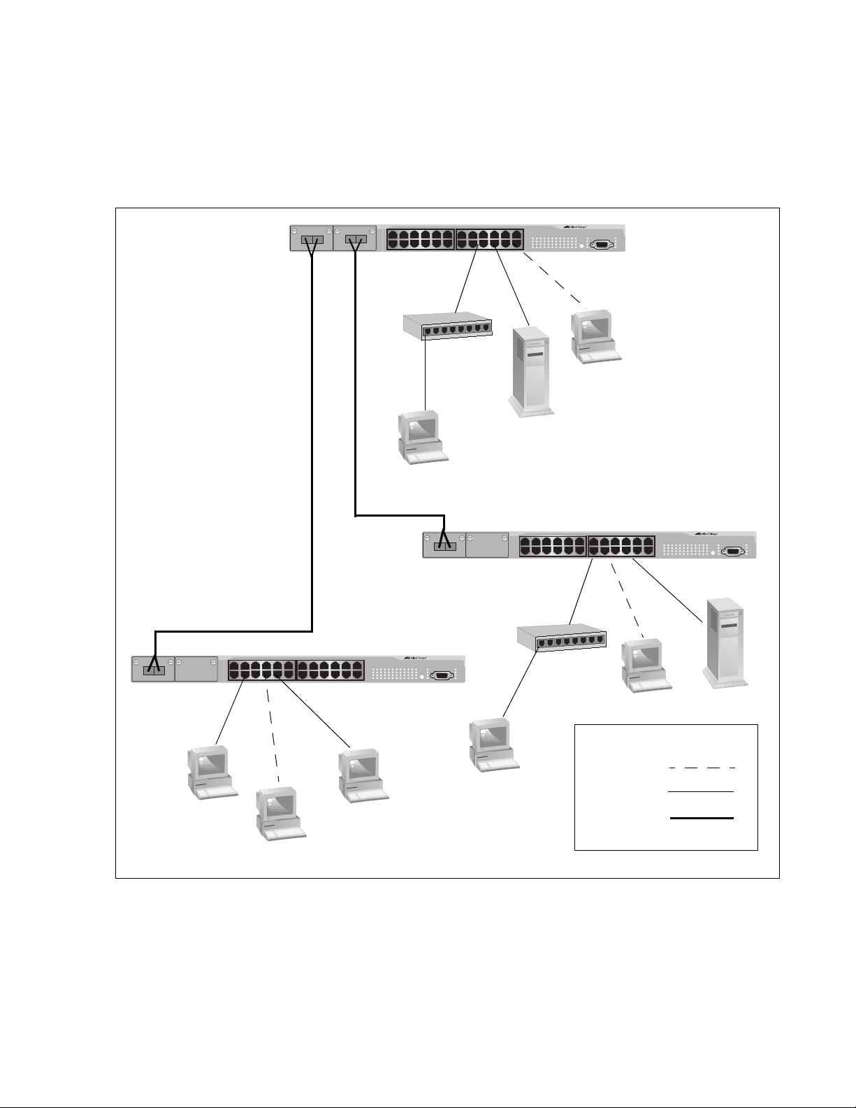
AT-8500 Series Layer 2+ Fast Ethernet Switches Installation Guide
AT-8524M Fast
Ethernet Switch
AT-8524M Fast
Ethernet Switch
AT-8524M Fast
Ethernet Switch
Legend
10 Mbps
100 Mbps
1000 Mbps
Fiber Optic
Figure 11 illustrates a network of three AT-8524M Fast Ethernet switches.
The workstations and servers on the network are connected either directly
to a switch or indirectly through an Ethernet hub. The switches themselves
are connected together through 1000Base fiber optic ports on AT-A45/SC
expansion modules, creating a high-speed backbone.
AT-8524M
8
7
6
5
4
3
2
1
AT-8524M
8
7
6
5
4
3
2
1
AT-8524M
Figure 11. Mixed Topology
45
Page 46

Chapter 1: Overview
46
Page 47

Chapter 2
Note
Installation
This chapter provides the installation procedures for the switch and
contains the following sections:
“Reviewing Safety Precautions” on page 48
“Selecting a Site for the Switch” on page 51
“Planning the Installation” on page 52
“Unpacking the Switch” on page 54
“Installing the Switch in a Rack” on page 55
“Installing an Optional Expansion or Stacking Module” on page 58
“Installing an Optional GBIC” on page 60
“Installing an Optional SFP Transceiver” on page 62
“Cabling the Switch” on page 64
“Powering on an AC Powered Switch” on page 68
“Wiring and Powering on an DC Powered Unit” on page 70
“Starting a Local Management Session” on page 73
“Warranty Registration” on page 75
To install an optional redundant power supply, refer to the
installation guide included with the unit.
47
Page 48

Chapter 2: Installation
Note
Reviewing Safety Precautions
Please review the following safety precautions before you begin to install
the chassis or any of its components.
The indicates that a translation of the safety statement is
available in a PDF document titled “Translated Safety Statements”
(613-000405) on the Allied Telesis website at
www.alliedtelesis.com.
Warning: To prevent electric shock, do not remove the cover.
No user-serviceable parts inside. This unit contains hazardous
voltages and should only be opened by a trained and qualified
technician. To avoid the possibility of electric shock, disconnect
electric power to the product before connecting or disconnecting
the LAN cables.
E1
Warning: Do not work on equipment or cables during periods of
lightning activity.
Warning: Power cord is used as a disconnection device. To deenergize equipment, disconnect the power cord.
Warning: Class I Equipment. This equipment must be earthed.
The power plug must be connected to a properly wired earth
ground socket outlet. An improperly wired socket outlet could
place hazardous voltages on accessible metal parts.
Pluggable Equipment. The socket outlet shall be installed near
the equipment and shall be easily accessible.
Caution: Air vents must not be blocked and must have free
access to the room ambient air for cooling.
Warning: Operating Temperature. This product is designed for a
maximum ambient temperature of 40° degrees C.
E2
E6
E5
E3
E7
E4
48
All Countries: Install product in accordance with local and
National Electrical Codes.
E8
Page 49

AT-8500 Series Layer 2+ Fast Ethernet Switches Installation Guide
Warning: As a safety precaution, install a circuit breaker with a
minimum value of 15 Amps between the equipment and the DC
power source.
Always connect the wires to the LAN equipment first before you
connect the wires to the circuit breaker. Do not work with HOT
feeds to avoid the danger of physical injury from electrical shock.
Always be sure that the circuit breaker is in the OFF position
before connecting the wires to the breaker.
Warning: Do not strip more than the recommended amount of
wire. Stripping more than the recommended amount can create
a safety hazard by leaving exposed wire on the terminal block
after installation.
Warning: When installing this equipment, always ensure that
the frame ground connection is installed first and disconnected
last.
E11
E10
E9
Warning: Check to see if there are any exposed copper strands
coming from the installed wire. When this installation is done
correctly there should be no exposed copper wire strands
extending from the terminal block. Any exposed wiring can
conduct harmful levels of electricity to persons touching the
wires. E12
This system works with positive grounded or negative grounded
E21
E13
E24
DC systems.
Circuit Overloading: Consideration should be given to the
connection of the equipment to the supply circuit and the effect
that overloading of circuits might have on overcurrent protection
and supply wiring. Appropriate consideration of equipment
nameplate ratings should be used when addressing this
concern.
A tray cable is required to connect the power source if the unit is
powered by centralized DC power. The tray cable must be a UL
listed Type TC tray cable and rated at 600 V and 90 degrees C,
with three conductors, minimum 14 AWG.
Warning: Mounting of the equipment in the rack should be such
that a hazardous condition is not created due to uneven
mechanical loading.
E25
49
Page 50

Chapter 2: Installation
Warning: This unit might have more than one power source. To
reduce the risk of electric shock, disconnect all power sources
before servicing the unit.
E30
If installed in a closed or multi-unit rack assembly, the operating
ambient temperature of the rack environment may be greater
than the room ambient temperature. Therefore, consideration
should be given to installing the equipment in an environment
compatible with the manufacturer’s maximum rated ambient
temperature (Tmra). E35
Caution: Installation of the equipment in a rack should be such
that the amount of air flow required for safe operation of the
equipment is not compromised.
E36
Warning: Reliable earthing of rack-mounted equipment should
be maintained. Particular attention should be given to supply
connections other than direct connections to the branch circuits
(e.g., use of power strips).
E37
Warning: To reduce the risk of electric shock, the PoE ports on
this product must not connect to cabling that is routed outside
the building where this device is located.
E40
50
Page 51

Selecting a Site for the Switch
Observe the following requirements when choosing a site for your switch:
If you plan to install the switch in an equipment rack, check to be sure
that the rack is safely secured and that it will not tip over. Devices in a
rack should be installed starting at the bottom, with the heavier devices
near the bottom of the rack.
If you are installing the switch on a table, be sure that the table is level
and secure.
The power outlet for the switch should be located near the unit and
should be easily accessible.
The site should provide for easy access to the ports on the front of the
switch. This will make it easy for you to connect and disconnect cables,
as well as to view the switch’s LEDs.
To allow proper cooling of the switch, air flow around the unit and
through its vents on the side and rear should be unrestricted.
AT-8500 Series Layer 2+ Fast Ethernet Switches Installation Guide
Do not place objects on top of the switch.
Do not expose the switch to moisture or water.
Make sure that the site is a dust-free environment.
You should use dedicated power circuits or power conditioners to
supply reliable electrical power to the network devices.
51
Page 52

Chapter 2: Installation
Note
Note
Planning the Installation
Table 10 contains the cabling specifications for the twisted pair ports.
Model Speed Cable Type
Table 10. Twisted Pair Cabling and Distances
Maximum
Operating
Distance
AT-8524M
AT-8524POE
AT-8550GB
AT-8550SP
AT-8550GB
AT-8550SP
(Ports 49R
and 50R)
The twisted pair ports on the switch feature auto-MDI/MDI-X. They
configured themselves automatically as MDI or MDI-X when
connected to an end node. This allows you to use a straight-through
twisted pair cable when connecting any type of network device to a
port on the switch.
10 Mbps Category 3 or better
100-ohm shielded or
unshielded twisted pair
cable
100 Mbps Category 5 or Category
5E (Enhanced)
100-ohm shielded or
unshielded twisted pair
cable
1000 Mbps Category 5 and
Category 5E
(Enhanced) 100-ohm
shielded or unshielded
twisted pair cable
100 m (328 ft)
100 m (328 ft)
100 m (328 ft)
The auto-MDI/MDI-X feature is disabled if you disable AutoNegotiation on a port and set a port’s speed and duplex mode
manually using the AT-S62 management software. A port where
Auto-Negotiation has been disabled defaults to MDI-X. Disabling
Auto-Negotiation may require that you manually configure a port’s
MDI/MDI-X setting or use a crossover cable.
The 10/100/1000Base-T ports, Ports 49R and 50R, on the
AT-8550GB and AT-8550SP switches can operate at 1000 Mbps
only when set to Auto-Negotiation, which is the default setting. You
cannot manually set these ports to 1000 Mbps.
52
Page 53

AT-8500 Series Layer 2+ Fast Ethernet Switches Installation Guide
Note
Table 11 contains the cabling specifications for the fiber optic ports on an
AT-8516F/SC switch.
Table 11. Fiber Optic Cabling and Distances
Maximum
Model Speed Cable Type
Operating
Distance
AT-8516F/SC 100 Mbps 50/125 or 62.5/125
micron (core/cladding)
multimode fiber optic
cable
For cabling specifications for an optional GBIC module, SFP
module, expansion module, or stacking module, refer to the
installation guide included with the option.
Full-duplex
mode: 2 km
(1.25 mi)
Half-duplex
mode: 412 m
(1,360 ft)
53
Page 54

Chapter 2: Installation
Note
Unpacking the Switch
To unpack the switch, perform the following procedure:
1. Remove all components from the shipping package.
2. Place the switch on a level, secure surface.
3. Make sure the following hardware components are included in your
Store the packaging material in a safe location. You must use the
original shipping material if you need to return the unit to Allied
Telesis.
switch package. If any item is missing or damaged, contact your Allied
Telesis sales representative for assistance.
One AT-8500 Series Fast Ethernet Switch
Two mounting brackets
Eight flathead Phillips screws (All models except the AT-8524POE
switch)
Twelve flathead Phillips screws (AT-8524POE switch only)
AC power cord (AC switches only; Americas, EC, Australia, and
UK only)
Management cable for local management
Documentation CD
Warranty card
54
Page 55

Installing the Switch in a Rack
Note
17
19 21 23
18
20 22 24
COL
100
FULL
ACT
FAULT
RPS
MASTER
PWR
M
ODE
STATUS
AT-8524M
Fast E
thernet Sw
itch
17
19 21 23
18
20 22 24
COL
100
FULL
ACT
FAULT
RPS
MASTER
PW
R
MO
DE
STATUS
AT-8524M
Fast Ethernet Switch
17 19 21 23
18
20 22 24
COL
100
FULL
ACT
FAULT
RPS
MASTER
PWR
M
ODE
STATUS
AT-8524M
Fast Ethernet Switch
17
19 21 23
18 20 22 24
COL
100
FULL
ACT
FAULT
RPS
MASTER
PWR
M
ODE
STATUS
AT-8524M
Fast Ethernet Sw
itch
AB
CD
The switch is shipped with two brackets for mounting the unit in a rack.
The brackets can be attached to the chassis four ways. You can install the
chassis so that it is flush with the front of the rack or so that it extends
forward from the rack. Figure 12 illustrates the different ways that you can
install the brackets and how much the chassis extends from the front of the
rack.
Method A - Flush with front of rack
Method B - 4.5cm (1.75 in.)
Method C - 18.4 cm (7.25 in.)
Method D - 21.6 cm (8.5 in)
AT-8500 Series Layer 2+ Fast Ethernet Switches Installation Guide
Figure 12. Rack Mount Bracket Positions
The AT-8524POE switch only supports Method A.
Perform the following procedure to install the switch in a standard 19-inch
rack. If you are not installing the switch in a rack, proceed to “Installing an
Optional GBIC” on page 60.
1. Place the unit upside down on a level, secure surface.
55
Page 56

Chapter 2: Installation
2. Using a flat-head screwdriver, remove the snap-on plastic feet from
the bottom of the switch, as shown in Figure 13.
Figure 13. Removing the Feet
3. Turn the switch over.
4. Attach a rackmounting bracket to one side of the switch using four of
the screws that came with the switch. You can install the brackets in
one of four ways, as shown in Figure 12.
5. Install the second rackmounting bracket on the other side of the switch
using the four remaining screws.
6. Mount the switch in the 19-inch rack using standard screws (not
provided).
Warning: To prevent electric shock, do not remove the cover.
No user-serviceable parts inside. This unit contains hazardous
voltages and should only be opened by a trained and qualified
technician. To avoid the possibility of electric shock, disconnect
electric power to the product before connecting or disconnecting
the LAN cables.
E1
Warning: Do not work on equipment or cables during periods of
lightning activity.
E2
Warning: Power cord is used as a disconnection device. To deenergize equipment, disconnect the power cord.
E3
Warning: Class I Equipment. This equipment must be earthed.
The power plug must be connected to a properly wired earth
ground socket outlet. An improperly wired socket outlet could
place hazardous voltages on accessible metal parts.
E4
56
Pluggable Equipment. The socket outlet shall be installed near
the equipment and shall be easily accessible.
E5
Page 57

AT-8500 Series Layer 2+ Fast Ethernet Switches Installation Guide
Caution: Air vents must not be blocked and must have free
access to the room ambient air for cooling.
E6
Warning: Operating Temperature. This product is designed for a
maximum ambient temperature of 40° degrees C.
E7
Circuit Overloading: Consideration should be given to the
connection of the equipment to the supply circuit and the effect
that overloading of circuits might have on overcurrent protection
and supply wiring. Appropriate consideration of equipment
nameplate ratings should be used when addressing this
concern.
E21
Warning: Mounting of the equipment in the rack should be such
that a hazardous condition is not created due to uneven
mechanical loading.
E25
If installed in a closed or multi-unit rack assembly, the operating
ambient temperature of the rack environment may be greater
than the room ambient temperature. Therefore, consideration
should be given to installing the equipment in an environment
compatible with the manufacturer’s maximum rated ambient
temperature (Tmra). E35
Caution: Installation of the equipment in a rack should be such
that the amount of air flow required for safe operation of the
equipment is not compromised.
E36
Warning: Reliable earthing of rack-mounted equipment should
be maintained. Particular attention should be given to supply
connections other than direct connections to the branch circuits
(e.g., use of power strips).
E37
57
Page 58

Chapter 2: Installation
Note
Note
Warning
Installing an Optional Expansion or Stacking Module
This section describes how to install an optional expansion or stacking
module in the switch and applies to the AT-8516F/SC, AT-8524M, and
AT-8524POE models.
The modules can be hot-swapped; you do not have to power off a
switch to install these options.
To install a module, perform the following procedure:
1. Remove the module from its shipping container and store the packaging material in a safe location.
You must use the original shipping material if you need to return the
module to Allied Telesis.
An expansion or stacking module can be damaged by static
electricity. Be sure to observe all standard electrostatic discharge
(ESD) precautions, such as wearing an antistatic wrist strap, to
avoid damaging the module.
Refer to the module’s installation guide for a list of the items included
with the option. If any item is missing or damaged, contact your Allied
Telesis sales representative for assistance.
2. Locate the expansion slots on the left side of switch.
3. Using a Phillips screwdriver, loosen the captive screws on the
faceplate and remove it, as shown in Figure 14.
58
Figure 14. Removing the Expansion Slot Faceplate
Page 59

AT-8500 Series Layer 2+ Fast Ethernet Switches Installation Guide
Caution
Note
1
0/100/1000BASE-T
AT-A46
10
100
FULL DUPLEX
ACTIVITY
LINK
1000
10/100/1000BASE-T
AT-A46
10
100
FULL DUP
L
EX
ACTIVITY
LINK
1000
4. Pull the faceplate straight out of the slot.
5. Keep the faceplate in a safe area in case you need to reinstall it.
The faceplate keeps any dust from getting into the switch and
maintains proper airflow if the slot remains empty.
6. Carefully slide the module into the slot until the module faceplate
makes contact with the switch, as shown in Figure 15.
Avoid touching the module components.
Figure 15. Installing a Module
7. Using a Phillips screwdriver, tighten the captive screws, as shown in
Figure 16, to secure the module in the switch.
Figure 16. Securing the Module in the Expansion Slot
Always use the captive screws to secure the module to the switch.
Leaving a module partially seated may cause the system to halt and
subsequently crash.
When you remove a module, store the device in an antistatic bag or
immediately install it in another switch.
59
Page 60

Chapter 2: Installation
Note
Note
Warning
Note
Installing an Optional GBIC
To install an optional GBIC in an AT-8550GB switch, perform the following
procedure:
A GBIC can be hot-swapped; you do not have to power off a switch
to install it.
1. Remove the GBIC from its shipping container and store the packaging material in a safe location.
You must use the original shipping material if you need to return the
module to Allied Telesis.
A GBIC can be damaged by static electricity. Be sure to observe all
standard electrostatic discharge (ESD) precautions, such as
wearing an antistatic wrist strap, to avoid damaging the module.
2. Check that the GBIC package includes all the items listed below.
If any item is missing or damaged, contact your Allied Telesis sales
representative for assistance.
One GBIC module
Installation Guide
Warranty card
For fiber optic cabling specifications, refer to the GBIC installation
guide provided with your module.
3. Follow these guidelines to ensure proper performance of your GBIC:
GBIC modules are dust sensitive. When the GBIC is stored or
when a fiber-optic cable is not plugged in, always keep plugs in the
GBIC optical bores.
60
The most common source of contaminants in the optical bore is
debris picked up on the ferrules of the optical connectors, as
shown in Figure 17. Use an alcohol swab or wipe to clean the
Page 61

AT-8500 Series Layer 2+ Fast Ethernet Switches Installation Guide
Note
Note
Ferrule
Bore
LINK
LINK
MODE LINK49R
MODE LINK50R
10/100/1000BASE-T
49
50
1
000
BAS
E-X
UPLINK P
OR
TS
ferrules of the optical connector.
Figure 17. Optical Bore and Ferrule of GBIC Module
Unnecessary removal and insertion of a GBIC can lead to premature
failure.
4. Slide the GBIC module, with the label side up, into an expansion slot
on the switch, as shown in Figure 18.
The GBIC can be installed in either slot. The GBIC module is seated in
the slot when it clicks into place.
Figure 18. Installing a GBIC Module
5. If you purchased two GBIC modules for the switch, repeat this
procedure to install the second module.
Unnecessary removal and insertion of a GBIC can lead to premature
failure.
61
Page 62

Chapter 2: Installation
Note
Note
Warning
Note
Installing an Optional SFP Transceiver
To install an optional SFP transceiver in an AT-8550SP switch, perform
the following procedure:
An SFP transceiver can be hot-swapped; you do not have to power
off a switch to install it.
1. Unpack the SFP transceiver from its shipping container and store the packaging material in a safe location.
You must use the original shipping material if you need to return the
module to Allied Telesis.
An SFP transceiver can be damaged by static electricity. Be sure to
observe all standard electrostatic discharge (ESD) precautions,
such as wearing an antistatic wrist strap, to avoid damaging the
module.
2. Check that the SFP transceiver includes the items listed below. If any
item is missing or damaged, contact your Allied Telesis sales
representative for assistance.
One SFP module
Installation Guide
Warranty card
For fiber optic cabling specifications, refer to the SFP installation
guide provided with the module.
3. Follow these guidelines to ensure proper performance of your SFP
transceiver:
SFP transceivers are static sensitive. To prevent Electrostatic
Discharge (ESD) damage, follow your normal board and
component handling procedures.
62
SFP transceivers are dust sensitive. Do not remove the dust cover
from the port until you are ready to attach the fiber optic cable.
The most common source of contaminants in the optical bore is
Page 63

AT-8500 Series Layer 2+ Fast Ethernet Switches Installation Guide
Note
Note
Note
debris picked up on the ferrules of the optical connectors. Use an
alcohol swab or wipe to clean the ferrules of the optical connector.
Unnecessary removal and insertion of an SFP transceiver can lead
to premature failure.
4. Remove the dust plug from the SFP slot.
5. Locate the label on the transceiver and turn it so that the label is on top
and the alignment groove is on the bottom.
6. Slide the SFP transceiver into an SFP slot on the switch.
The SFP module can be installed in either slot. The SFP module is
seated in the slot when it clicks into place.
SFP transceivers are dust sensitive. When a fiber optic cable is not
installed, or when you store the SFP, always keep the plug in the
slot. When you do remove the plug, keep it for future use.
Unnecessary removal and insertion of an SFP transceiver can lead
to premature failure.
7. If you purchased two SFP transceivers for the switch, repeat this
procedure to install the second transceiver.
For information about cabling for the SFP transceiver, consult the
documentation that was shipped with the SFP.
63
Page 64

Chapter 2: Installation
1
3
5
2
4
6
26
Cabling the Switch
To connect the data cables to the switch ports and to apply power to the
switch, perform the following procedure:
Cabling Twisted
Pair Ports
If your AT-8500 Series switch has twisted pair ports, perform the following
procedure:
1. Connect the twisted pair data cables to the RJ-45 ports on the switch, as shown in Figure 19.
Figure 19. Connecting the Twisted Pair Data Cables
When you connect a twisted pair cable to a port, observe the following
guidelines:
An RJ-45 connector should fit snugly into the port on the switch.
The tab on the connector should lock the connector into place.
Because the ports on the switch are auto-MDI/MDI-X, you can use
either a straight-through or crossover twisted pair cable to connect
any type of network device to a port on the switch. If you disable
Auto-Negotiation on a port, the auto-MDI/MDI-X feature is disabled
and the port defaults to MDI-X. For instructions on how to
configure a port, refer to the AT-S62 Management Software User’s
Guides.
If your network topology will contain a loop where two or more
network devices can communicate with each other over more than
one data path, do not connect the network cables forming the loop
until after you have activated a spanning tree protocol on the
switch. Data loops can adversely affect network performance. For
information on spanning tree, refer to the AT-S62 Management
Software User’s Guides.
If you are creating a port trunk, do not connect the cables of the
trunk to the switch until you after have configured the trunk using
the switch’s management software. Connecting the trunk cables to
the switch before you have configured the software will result in a
data loop, which can adversely affect network performance. For
64
Page 65

AT-8500 Series Layer 2+ Fast Ethernet Switches Installation Guide
Warning
Note
18
D/
C
L/A
D/
C
L/A
TX
TX
1
TX
RX
9
TX RX
instructions on how to configure a port trunk, refer to the AT-S62
Management Software User’s Guides.
When you connect a device to a port on an AT-8524POE switch,
the port automatically determines whether the node is a powered
device and, if it is, the amount of wattage required by the device,
up to a maximum of 15.4 W. If the node is not a powered device,
the port automatically disables the PoE feature.
To reduce the risk of electric shock, the PoE ports on this product
must not connect to cabling that is routed outside the building where
this device is located. E40
Cabling Fiber
Optic Ports
If your switch has fiber optic ports, perform the following procedure:
1. Remove the dust covers from the ports, as shown in Figure 20.
Figure 20. Removing the Dust Covers from the Fiber Optic Ports
Do not remove the dust covers if you do not intend to connect the
fiber optic cables at this time. Dust contamination can adversely
impact the operation of the ports.
65
Page 66

Chapter 2: Installation
18
D/C
L/A
D
/
C
L
/A
TX
TX
1
TX RX
9
TX
RX
SC Port
Transmitter
Fiber
Connector
Receiver
Fiber
Connector
2. Attach the fiber optic data cables to the fiber optic ports, as shown in
Figure 21.
Figure 21. Attaching a Fiber Optic Cable
When you attach a fiber optic cable, be sure to observe the following
guidelines:
Be sure that the cable connector is firmly locked into place in the
port.
A dual SC port consists of two separate connectors, as shown in
Figure 22. Each connects to a separate fiber strand. One is for
receiving packets and the other is for transmitting packets. When
you connect a fiber optic cable to a dual SC port, be sure that the
receiver fiber connector is connected to the transmitter connector
on the remote end node, and the transmitter fiber connector is
connected to the receiver connector on the remote node.
1TX RX
Figure 22. Dual SC Port
You should verify that you are using the appropriate type of fiber
optic cabling. For an AT-8516F/xx Series switch, refer to “Planning
the Installation” on page 52. For an optional GBIC module, refer to
the GBIC installation guide. For an optional fiber optic expansion
module, refer to the expansion module installation guide.
You should verify that the operating specifications of the switch’s
66
fiber optic port are compatible with the fiber optic port on the
Page 67

AT-8500 Series Layer 2+ Fast Ethernet Switches Installation Guide
remote end node. For example, you cannot connect a fiber optic
port with a maximum distance of 2 kilometers and an operating
wavelength of 1310 nm to another fiber optic port that has a
maximum distance of 40 kilometers (24.8 miles) and an operating
wavelength of 1550 nm. For fiber optic ports specifications, refer to
“AT-8516F/SC Fiber Optic Port Specifications” on page 85.
If your network topology will contain a loop where two or more
network devices can communicate with each other over more than
one data path, do not connect the network cables forming the loop
until after you have activated a spanning tree protocol on the
switch. Data loops can adversely affect network performance. For
information on spanning tree, refer to the AT-S62 Management
Software User’s Guides.
If you are creating a port trunk, do not connect the cables of the
trunk to the switch until you after have configured the trunk using
the switch’s management software. Connecting the trunk cables to
the switch before you have configured the software will result in a
data loop, which can adversely affect network performance. For
instructions on how to configure a port trunk, refer to the AT-S62
Management Software User’s Guides.
Cabling
Expansion
Modules
If you installed a fiber optic or twisted pair expansion module, stacking
module, GBIC module, or SFP module, connect the data cable to the port
on the module.
67
Page 68

Chapter 2: Installation
Note
Warning
Powering on an AC Powered Switch
To power on an AC powered switch, perform the following procedure:
If you are installing a DC powered switch, go to “Wiring and
Powering on an DC Powered Unit” on page 70.
1. Select the correct power cord for your country.
2. Plug the power cord into the AC power connector on the back panel of
the switch, as shown in Figure 23.
The power cord is used as a disconnection device. To de-energize
equipment, disconnect the power cord. E3
68
Figure 23. Connecting the AC Power Cord
3. Plug the other end of the power cord into a wall outlet.
When power is applied, the switch begins to load the AT-S62 software.
The loading process takes approximately 20 to 30 seconds to complete.
Page 69

AT-8500 Series Layer 2+ Fast Ethernet Switches Installation Guide
Warning
4. If you installed an optional redundant power supply unit, connect one
end of the DC power cord included with the RPS unit to the back panel
of the redundant power supply and the other end to the RPS connector
on the back panel of the switch, as shown in Figure 24.
Figure 24. Connecting the RPS DC Cable
5. Verify that the PWR LED on the front of the unit is green. If the PWR
LED is OFF, refer to Chapter 3, “Troubleshooting” on page 77.
The switch runs a series of self-diagnostic tests, which take a few
seconds to perform. After the self tests are complete, the switch is
ready for normal network operations.
This unit might have more than one power cord. To reduce the risk
of electric shock, disconnect all power cords before servicing the
unit. E30
No further installation steps are required if you do not intend to change
the default operating parameter settings of the switch, which are listed
in the AT-S62 Management Software User’s Guide. However, if you
want to manage the switch, refer to “Starting a Local Management
Session” on page 73.
69
Page 70

Chapter 2: Installation
Warning
Wiring and Powering on an DC Powered Unit
To provide power for a DC powered switch, perform the following steps:
1. Before you attach wires to the DC terminal block at the rear of the switch, review the following warning:
As a safety precaution, install a circuit breaker with a minimum value
of 15 Amps between the equipment and the DC power source.
Always connect the wires to the LAN equipment first before you
connect the wires to the circuit breaker. Do not work with HOT feeds
to avoid the danger of physical injury from electrical shock. Always
be sure that the circuit breaker is in the OFF position before
connecting the wires to the breaker. E9
A tray cable is required to connect the power source if the unit is
powered by centralized DC power. The tray cable must be a UL
listed Type TC tray cable and rated at 600 V and 90 degrees C, with
three conductors, minimum 14 AWG. E24
2. On the rear side of the chassis is a DC terminal block. Starting from
the left side of the terminal block, identify the positive, frame ground,
and negative terminals using the symbols beneath the terminal block
or the illustration in Figure 25.
DC INPUT
36-60VDC
Ground
Negative
Positive
FOR CENTRALIZED DC
POWER CONNECTION,
INSTALL ONLY IN A
RESTRICTED AREA
Figure 25. Positive, Ground, and Negative Terminals
70
3. With a 14-gauge wire-stripping tool, strip the three wires in the tray
cable coming from the DC input power source to 8mm ± 1mm (0.31 in.,
± 0.039 in.).
Page 71

AT-8500 Series Layer 2+ Fast Ethernet Switches Installation Guide
Warning
Warning
Warning
40-60VDC
452
Do not strip more than the recommended amount of wire. (See
Figure 26.) Stripping more than the recommended amount can
create a safety hazard by leaving exposed wire on the terminal block
after installation. E10
8mm ±1mm
(0.31in. ±0.039in.)
451
Figure 26. Stripped Wire
4. Connect the frame ground wire to the terminal marked with the
ground symbol by inserting the wire into the terminal and tightening the
connection with a flathead screwdriver, as shown in Figure 27.
When installing this equipment, always ensure that the frame ground
connection is installed first and disconnected last. E11
Figure 27. Connecting the Stripped Wire
5. Connect the positive feed wire to the terminal block marked (+).
6. Connect the negative feed wire to the terminal block marked (-).
Check to see if there are any exposed copper strands coming from
the installed wires. When this installation is done correctly there
should be no exposed copper wire strands extending from the
terminal block. Any exposed wiring can conduct harmful levels of
electricity to persons touching the wires. E12
71
Page 72

Chapter 2: Installation
Warning
7. Secure the tray supply cable near the rack framework using multiple
cable ties to minimize the chance of the connections being disturbed
by casual contact with the wiring. Use at least four cable ties
separated four inches apart with the first one located within six inches
of the terminal block.
This system works with a positive grounded or negative grounded
DC system. E13
8. Ensure that the circuit breaker is in the Off position.
9. Connect the DC wires to the circuit breaker. (Refer “Power
Specifications” on page 82 for power requirements.)
10. Power on the circuit breaker.
11. Verify that the PWR LED on the front of the unit is green. If the PWR
LED is OFF, refer to Chapter 3, “Troubleshooting” on page 77.
The switch runs a series of self-diagnostic tests, which take a few
seconds to perform. After the self tests are complete, the switch is
ready for normal network operations.
This unit might have more than one power cord. To reduce the risk
of electric shock, disconnect all power cords before servicing the
unit. E30
No further installation steps are required if you do not intend to change
the default operating parameter settings of the switch, which are listed
in the AT-S62 Management Software User’s Guide. However, if you
want to manage the switch, refer to “Starting a Local Management
Session” on page 73.
72
Page 73

Starting a Local Management Session
Note
FAULT
RPS
MASTER
PWR
STAT US
AT-8524M
Fast Ethernet Switch
COL
100
FULL
ACT
MODE
The procedure in this section explains how to start a local (out-of-band)
management session using the RS-232 terminal port on the switch. You
can use a local management session to configure the switch’s operating
parameters and view performance and error statistics.
If you already installed an AT-8500 Series Switch, AT-8400 Series
Switch, or AT-8000 Series Switch on your network and configured it
as a Master switch of an enhanced stack, you can begin to remotely
manage the new switch you have just installed by connecting, locally
or remotely, to the Master switch and then using the enhanced
stacking feature to access the new switch. For instructions, refer to
the AT-S62 Management Software User’s Guides.
To start a local management session, perform the following procedure:
AT-8500 Series Layer 2+ Fast Ethernet Switches Installation Guide
1. Connect one end of the RS-232, straight-through management cable
included with the AT-8500 Series switch to the RS-232 terminal port on
the switch. (See Figure 28.) This port is located on the front panel on
the AT-8516F/SC, AT-8524M, and AT-8524POE switches and on the
back panel of the AT-8550GB and AT-8550SP switches.
Figure 28. Connecting an RS-232 Cable to the RS-232 Terminal Port on
an AT-8524M Switch
2. Connect the other end of the cable to an RS-232 port on a terminal or
a personal computer with a terminal emulation program.
3. Set the terminal or the terminal emulation program to the following
settings:
Baud rate: 9600 bps
Data bits: 8
73
Page 74

Chapter 2: Installation
Note
Note
Parity: None
Stop bits: 1
Flow control: None
The port settings are for a DEC VT100 or ANSI terminal, or an
equivalent terminal emulator program.
When you reset or power cycle the switch during a local
management session, you will see the following prompt: Press
<CTRL>B to go to Boot Prompt. This message is intended for
manufacturing purposes only. If you inadvertently display the boot
prompt (=>), type boot and press Return to start the switch.
4. Press Return.
You are prompted for a user name and password.
5. To view and configure all of the switch’s operating parameters, enter
the login name “manager”. The default password for manager access
is “friend”. To only view the parameter settings, enter the login name
“operator”. The default password for operator access is “operator”. The
user names and passwords are case-sensitive.
The Main Menu is displayed.
If you logged in with manager access, you can now fully manage the
switch using the management interface. For instructions, refer to the
AT-S62 Management Software User’s Guides. The guides are
available from the Allied Telesis web site at www.alliedtelesis.com and
on the CD included with the switch.
74
Page 75

Warranty Registration
When you have finished installing the switch, fill out the enclosed warranty
card and mail it to Allied Telesis.
AT-8500 Series Layer 2+ Fast Ethernet Switches Installation Guide
75
Page 76

Chapter 2: Installation
76
Page 77

Chapter 3
Troubleshooting
This chapter contains information on how to troubleshoot the switch in the
event that a problem occurs.
If after following the instructions in this chapter you are unable to
resolve the problem, contact Allied Telesis Technical Support for
assistance. Refer to “Contacting Allied Telesis” on page 14 for
contact information.
PWR LED is Off
Check the PWR LED on the front of the switch. If the LED is OFF,
indicating that the unit is not receiving power, do the following:
Make sure that the power cord is securely connected to the power
source and to the AC connector on the back panel of the switch.
Verify that the power outlet has power by connecting another device to
it.
Try connecting the unit to another power source.
Try using a different power cord.
Check that the voltage from the power source is within the required
levels for your region.
Twisted Pair Port Link LED is Off
For twisted pair ports, verify that the LINK LED for each port is ON. If a
Link LED is OFF, do the following:
Verify that the end node connected to the port is powered ON and is
operating properly.
Check that the twisted pair cable is securely connected to the port on
the switch and to the port on the end node.
Make sure that the twisted pair cable does not exceed 100 m
(328 ft).
77
Page 78

Chapter 3: Troubleshooting
Verify that you are using the appropriate category of twisted pair cable:
Category 3 or better for 10 Mbps operation and Category 5 and
Category 5E for 100 Mbps and 1000 Mbps operations.
Determine if a crossover cable is required. Since the twisted pair ports
feature auto MDI/MDI-X, you should be able to use a straight-through
cable regardless of the type of device you connect to a port. However,
if you disable Auto-Negotiation on a port and set a port’s speed and
duplex mode manually, the port defaults to MDI-X. For port pinouts,
refer to “RJ-45 Twisted Pair Port Pinouts” on page 83.
Make sure that the operating parameters of the port on the switch are
compatible with the end node to which the port is connected. This may
require that you use the switch’s management software. For
instructions, refer to the AT-S62 Management Software User’s Guides.
Fiber Optic Port Link LED is Off
For fiber optic ports, verify that the LINK LED for each port is ON. If a LINK
LED is OFF, do the following:
Verify that the end node connected to the port is powered ON and is
operating properly.
Check that the fiber optic cable is securely connected to the port on
the switch and to the port on the end node.
Dual SC ports consist of two separate connectors, as shown in Figure
32 on page 90. Each connects to a separate fiber strand. One is for
receiving data and the other is for transmitting data. When connecting
a fiber optic cable to an SC port, be sure that the receiver fiber
connector is connected to the transmitter connector on the remote end
node, and the transmitter fiber connector is connected to the receiver
connector on the remote node.
Make sure that you are using the appropriate type of fiber optic cable
and that the cable length does not exceed the allowed maximum
distance. For an AT-8516F Series switch, refer to “Planning the
Installation” on page 52 . For an optional GBIC or SPF module, or
other expansion module, refer to the Installation Guide shipped with
the module.
Use a fiber optic tester to test the attenuation on the cable to
determine if the strength of the fiber optic signal falls below acceptable
limits. (For fiber optic port specifications for an AT-8516F Series
Switch, refer to “AT-8516F/SC Fiber Optic Port Specifications” on
page 85. For an optional GBIC or SPF module, or other expansion
module, refer to the Installation Guide shipped with the module.
78
Check that the operating specifications (for instance, wavelength and
maximum operating distance) of the fiber optic port on the remote end
node are compatible with the fiber optic port on the switch. For
Page 79

example, you cannot connect a fiber optic port with a maximum
distance of 40 kilometers (24.8 miles) and an operating wavelength of
1550 nm to a remote fiber optic port with an maximum distance of only
2 kilometers (1.24 miles) and a wavelength of 1310 nm.
Check to be sure that the fiber optic ports on the switch and on the end
node are operating at the same speed and duplex mode.
AT-8550GB and AT-8550SP switches only — Verify that the GBIC
module or SFP module is completely inserted into the expansion slot
on the front of the switch.
A 1000Base connection can take from five to ten seconds to
establish a link.
PoE Device is Not Receiving Power
If you attached a powered device to a port on an AT-8524POE, the PoE
LED for the port should be green. (Remember to use the Mode Select
button to toggle the Mode LEDs to the PoE state.) If the device is not
receiving power or the PoE LED is flashing amber, steady amber, or is
OFF, do the following:
AT-8500 Series Layer 2+ Fast Ethernet Switches Installation Guide
Check to be sure that the powered device is designed to receive power
over pins 1, 2, 3, and 6 on the RJ-45 port. This can be verified by
reviewing the device’s documentation or data sheet.
Check that the device’s power requirements do not exceed 15.4 W.
This can be verified by reviewing the device’s documentation or data
sheet.
Verify that the twisted pair cable is Category 5 or 5E.
Verify that the twisted pair cable is not faulty.
Use the AT-S62 management software to determine whether PoE is
enabled on the switch and the port. The default setting for PoE is
enabled.
Use the management software to determine whether the PoE power
setting for the port has been reduced from the default setting of 15.4
W, to a value below the power requirements of the device.
PoE is not supported on expansion modules.
Verify that the power budget on the switch is not being exceeded by
the powered devices. This should not be a problem for the
AT-8524POE switch, which can support powered devices on all ports 1
to 24, even when all devices require the maximum of 15.4 W.
Fault LED is On Continuously
79
Page 80

Chapter 3: Troubleshooting
Check the FAULT LED. During normal operations, the LED remains off,
except for periods when the management software is saving a change to
its configuration. If it remains on for an extended period, do the following:
Try resetting the switch by disconnecting and reconnecting the AC
power cord. If the switch is a DC model, reset the unit by powering off
and the powering on the DC circuit.
If the FAULT LED remains ON, try downloading a new version of the
switch’s management software through the RS-232 terminal port on
the front panel of the switch. For instructions, refer to the switch’s
software management guide.
If the LED remains on even after you have tried the above
suggestions, the switch may be having a hardware problem. Contact
your Allied Telesis representative for assistance.
Cannot Establish a Local Management Session
If you are unable to establish a local management session with the switch
through the RS-232 terminal port on the front panel, do the following:
Check to be sure that the RS-232 cable is securely connected to the
RS-232 terminal port on the switch and to the RS-232 port on the
terminal or personal computer.
Check to be sure that you are using a straight-through RS-232 cable.
Do not use a cross-over cable.
Check to be sure that the operating parameters on the terminal or the
terminal emulation program, if you are using a personal computer,
have been set correctly. The default settings for “Planning the
Installation” on page 52the RS-232 terminal port can be found in. See
“Planning the Installation” on page 52.
80
Page 81

Appendix A
Technical Specifications
Physical Specifications
AT-8516F/SC and AT-8524M 4.4 cm x 44.0 cm x 22.2 cm
Dimensions (1.75 in. x 17.3 in. x 8.75 in.)
AT-8550GB and AT-8550SP 4.4 cm x 44.0 cm x 25.5 cm
Dimensions (1.75 in. x 17.3 in. x 10.0 in.)
AT-8524POE Dimensions: 4.4 cm x 43.8 cm x 40.6 cm
(H x W x D)
(H x W x D)
(1.75 in. x 17.25 in. x 16.0 in.)
(H x W x D)
Weight:
AT-8516F/SC 3.4 kg (7.4 lb.)
AT-8524M 3.2 kg (7.1 lb.)
AT-8524POE 6.0 kg (13.3 lb.)
AT-8550GB 3.6 kg (7.9 lb.)
AT-8550SP 3.5 kg (7.7 lb.)
Recommended Minimum
Ventilation on All Sides: 10 cm (4.0 in)
Environmental Specifications
Operating Temperature: 0° C to 40° C (32° F to 104° F)
Storage Temperature: -25° C to 70° C (-13° F to 158° F)
Operating Humidity: 5% to 90% non-condensing
Storage Humidity: 5% to 95% non-condensing
Maximum Operating Altitude: 4,000 m (13,000 ft)
Maximum Non-operating Altitude:4,000 m (13,000 ft)
81
Page 82

Appendix A: Technical Specifications
Power Specifications
Input Voltage:
All models except for the AT-8524POE:
AC Input Power Consumption:
Available Power over Ethernet: 370 W @ 48 VDC
AC 100-240 VAC, 2A Max, 50/60 Hz
DC 36-60 VDC, 4A Max
AT-8524POE:
AC 100-240 VAC, 6A Max, 50/60 Hz
All models except AT-8524POE: 74 watts
Only the AT-8524POE: 450 watts
IEEE 802.3af Class 3 (15.4 W): Max 24 ports
IEEE 802.3af Class 2 (7.3 W): Max 24 ports
IEEE 802.3af Mode: Alternative A (MDI)
Safety and Electromagnetic Emissions Certifications
EMI: FCC Class A, EN55022 Class A,
VCCI Class A, C-TICK,
EN61000-3-2, EN61000-3-3
Immunity: EN55024
Safety: UL 60950 (
(TUV)
Quality and Reliability: MTBF > 90,000 hrs,
MTTR < 1/2 hr
cULus
), EN60950
82
Page 83

RJ-45 Twisted Pair Port Pinouts
Figure 29 illustrates the pin layout for an RJ-45 connector and port.
Figure 29. RJ-45 Connector and Port Pin Layout
Table 12 lists the RJ-45 pin signals for the 10/100Base-TX ports on the
AT-8524M, AT-8550GB, and AT-8550SP switches.
Table 12. 10/100Base-TX Port MDI/MDI-X Pin Signals
AT-8500 Series Layer 2+ Fast Ethernet Switches Installation Guide
Pin 1
Pin MDI Signal
MDI-X
Signal
1TX+ RX+
2TX- RX-
3RX+ TX+
4 Unused Unused
5 Unused Unused
6RX- TX-
7 Unused Unused
8 Unused Unused
Table 13 lists the RJ-45 port pin signals on the 10/100Base-TX ports on an
AT-8524POE switch.
Table 13. 10/100Base-T Port MDI/MDI-X Pin Signals with PoE
Pin MDI Signal MDI-X Signal
1
1 TX+ and Vport-1
RX+ and Vport-1
2 TX- and Vport-1 RX- and Vport-1
2
3 RX+ and Vport-2
TX+ and Vport-2
83
Page 84

Appendix A: Technical Specifications
Table 13. 10/100Base-T Port MDI/MDI-X Pin Signals with PoE
Pin MDI Signal MDI-X Signal
4 Unused Unused
5 Unused Unused
6 RX- and Vport-2 TX- and Vport-2
7 Unused Unused
8 Unused Unused
1. Vport-1 can be positive (+) or negative (-), depending on the requirements of the powered device connected to a port.
2. Vport-2 can be positive (+) or negative (-), depending on the requirements of the powered device connected to a port. If Vport-1 is positive, then Vport-2
will be negative. If Vport-1 is negative, then Vport-2
will be positive.
Table 14 lists the RJ-45 pin signals for the two 10/100/1000-Base-T ports
on the AT-8550GB switch when the ports are operating at 1000 Mbps.
Table 14. MDI and MDI-X Pin Signals (1000Base-T)
MDI Configuration MDI-X Configuration
Pinout Pair Pinout Pair
1 Pair 1 + 1 Pair 2 +
2 Pair 1 - 2 Pair 2 -
3 Pair 2 + 3 Pair 1 +
4 Pair 3 + 4 Pair 4 +
5 Pair 3 - 5 Pair 4 -
6 Pair 2 - 6 Pair 1 -
7 Pair 4 + 7 Pair 3 +
8 Pair 4 - 8 Pair 3 -
84
Page 85

AT-8500 Series Layer 2+ Fast Ethernet Switches Installation Guide
AT-8516F/SC Fiber Optic Port Specifications
Standard: 100Base-FX
Speed: 100 Mbps
Maximum Operating
Distance: 2 km (1.24 mi)
Connectors:
AT-8516F/SC Dual SC Connector
Type of Cabling: 50/125 micron or 62.5/125 micron
(core/cladding) multimode fiber optic
cabling
Operating Wavelength: 1310 nm
Transmitter Output Power:
50/125 micron cabling
Minimum: -22.5 dBm average
Maximum: -14 dBm average
62.5/125 micron cabling
Minimum: -19 dBm average
Maximum: -14 dBm average
Receiver Sensitivity:
Minimum: -31 dBm average
Maximum: -14 dBm average
85
Page 86

Appendix A: Technical Specifications
RS-232 Terminal Port Pinouts
Table 15 lists the pin signals on the RS-232 terminal port.
Table 15. RS-232 Terminal Port Pin Signals
Pin Signal
1 Data Carrier Detect
2 Transmit Data
3 Receive Data
4 Data Set Ready
5 Ground
6 Data Terminal Ready
7 Clear to Send
8 Request to Send
9 Ring Indicator
86
Page 87

RPS Connector Port Pinouts
Figure 30 illustrates the pin layout to the 16-pin molex connector and RPS
port on the AT-8516F/SC, AT-8524M, AT-8550GB, and AT-8550SP
switches.
16
8
Figure 30. RPS 16-pin Molex Connector Pin Layout
Table 16 lists the 16-pin RPS connector pins and definitions.
AT-8500 Series Layer 2+ Fast Ethernet Switches Installation Guide
9
9
1
1
16
8
Table 16. Pin Definitions of the 16-pin RPS Connector
Pin Definition
1+5V DC
2 Remote Sense (RS) +3.3 V DC
3RS -3.3 V DC
4RS +2.5V DC
5 Redundant Power Supply (RPS) present
6 +2.5V DC Return
7 +3.3V DC Return
8 +3.3V DC
9 +5V DC Return
10 +2.5V DC
11 +2.5 DC Return
12 +2.5V DC
13 +2.5V DC Return
14 +2.5V DC
15 +3.3V DC
87
Page 88

Appendix A: Technical Specifications
Table 16. Pin Definitions of the 16-pin RPS Connector (Continued)
Pin Definition
16 +3.3V DC Return
Figure 31 illustrates the pin layout to the RPS connector on the
AT-8524POE switch.
A1A2 17
15 8
Figure 31. AT-8524POE RPS Connector Pin Layout
Table 17 lists the RPS connector pins and definitions.
Table 17. Pin Definitions for the RPS Connector on the AT-8524POE
Switch
Pin Definition
A1 48V Return
A2 Return
1 48V
2 48V RS+
3 Redundant Power Supply (RPS) present
4 12V RS-
5 12V RS+
6 12V
73.3V
8 48V
88
9 48V
10 48V RS-
11 RPS GOOD
12 3.3V RS-
Page 89

AT-8500 Series Layer 2+ Fast Ethernet Switches Installation Guide
Table 17. Pin Definitions for the RPS Connector on the AT-8524POE
Switch (Continued)
Pin Definition
13 3.3V RS+
14 3.3V
15 3.3V
89
Page 90

Appendix A: Technical Specifications
Dual SC Type Connector
A dual SC type connector, as shown in Figure 32, is used with the
AT-8516F/SC switch.
Figure 32. Dual SC Connector
90
 Loading...