

Page 1

◆
User’s Guide
Gigabit
®
Switches
AT-9108
AT-8518
AT-8525
AT-8550
Version 4.x
PN 613-10793-00 Rev B
Page 2

Copyright 1999 Allied Telesyn International, Corp.
960 Sewart Drive Suite B, Sunnyvale CA 94086 USA
All rights reserved. No part of this publication may be reproduced without prior written permission from Allied Telesyn International,
Corp.
Centre
Com is a registered trademark of Allied Telesyn International, Corp.
All other product names, company names, logos or other designations mentioned herein are trademarks or registered trademarks of
their respective owners.
Allied Telesyn International, Corp. reserves the right to make changes in specifications and other information contained in this
document without prior written notice. The information provided herein is subject to change without notice. In no event shall Allied
Telesyn International, Corp. be liable for any incidental, special, indirect, or consequential damages whatsoever, including but not
limited to lost profits, arising out of or related to this manual or the information contained herein, even if Allied Telesyn International,
Corp. has been advised of, known, or should have known, the possibility of such damages.
Page 3

Table of Contents
Preface
Audience Description . . . . . . . . . . . . . . . . . . . . . . . . . . . . . . . . . . . . . . . . . . . . . . . . . . . . . . . . . . . . . . . . . . . . . . . . . . . . . . . . . . . . .Preface-ii
Document Conventions . . . . . . . . . . . . . . . . . . . . . . . . . . . . . . . . . . . . . . . . . . . . . . . . . . . . . . . . . . . . . . . . . . . . . . . . . . . . . . . . . . Preface-iii
Organization. . . . . . . . . . . . . . . . . . . . . . . . . . . . . . . . . . . . . . . . . . . . . . . . . . . . . . . . . . . . . . . . . . . . . . . . . . . . . . . . . . . . . . . . . . . . . Preface-iv
Related Publications . . . . . . . . . . . . . . . . . . . . . . . . . . . . . . . . . . . . . . . . . . . . . . . . . . . . . . . . . . . . . . . . . . . . . . . . . . . . . . . . . . . . . .Preface-v
Chapter 1
Overview
Summary of Features. . . . . . . . . . . . . . . . . . . . . . . . . . . . . . . . . . . . . . . . . . . . . . . . . . . . . . . . . . . . . . . . . . . . . . . . . . . . . . . . . . . . . . . . . . . . 1-1
Memory Requirements . . . . . . . . . . . . . . . . . . . . . . . . . . . . . . . . . . . . . . . . . . . . . . . . . . . . . . . . . . . . . . . . . . . . . . . . . . . . . . . . . . . . . . . . . . 1-5
Network Configuration Example . . . . . . . . . . . . . . . . . . . . . . . . . . . . . . . . . . . . . . . . . . . . . . . . . . . . . . . . . . . . . . . . . . . . . . . . . . . . . . . . . 1-6
Software Factory Defaults . . . . . . . . . . . . . . . . . . . . . . . . . . . . . . . . . . . . . . . . . . . . . . . . . . . . . . . . . . . . . . . . . . . . . . . . . . . . . . . . . . . . . . .1-8
Chapter 2
Accessing the Switch
Understanding the Command Syntax. . . . . . . . . . . . . . . . . . . . . . . . . . . . . . . . . . . . . . . . . . . . . . . . . . . . . . . . . . . . . . . . . . . . . . . . . . . . 2-2
Line-Editing Keys. . . . . . . . . . . . . . . . . . . . . . . . . . . . . . . . . . . . . . . . . . . . . . . . . . . . . . . . . . . . . . . . . . . . . . . . . . . . . . . . . . . . . . . . . . . . . . . . 2-5
Command History. . . . . . . . . . . . . . . . . . . . . . . . . . . . . . . . . . . . . . . . . . . . . . . . . . . . . . . . . . . . . . . . . . . . . . . . . . . . . . . . . . . . . . . . . . . . . . . 2-6
Common Commands . . . . . . . . . . . . . . . . . . . . . . . . . . . . . . . . . . . . . . . . . . . . . . . . . . . . . . . . . . . . . . . . . . . . . . . . . . . . . . . . . . . . . . . . . . . 2-7
Configuring Management Access. . . . . . . . . . . . . . . . . . . . . . . . . . . . . . . . . . . . . . . . . . . . . . . . . . . . . . . . . . . . . . . . . . . . . . . . . . . . . . .2-10
Methods of Managing the Switch. . . . . . . . . . . . . . . . . . . . . . . . . . . . . . . . . . . . . . . . . . . . . . . . . . . . . . . . . . . . . . . . . . . . . . . . . . . . . . .2-13
. . . . . . . . . . . . . . . . . . . . . . . . . . . . . . . . . . . . . . . . . . . . . . . . . . . . . . . . . . . . . . . . . . . . . . . . . . . . . . . . . . . . . . . . . . . . . . . . . . . Preface-i
. . . . . . . . . . . . . . . . . . . . . . . . . . . . . . . . . . . . . . . . . . . . . . . . . . . . . . . . . . . . . . . . . . . . . . . . . . . . . . . . . . . . . . . . . . . . . . . . . . . . . . 1-1
Virtual LANs (VLANs) . . . . . . . . . . . . . . . . . . . . . . . . . . . . . . . . . . . . . . . . . . . . . . . . . . . . . . . . . . . . . . . . . . . . . . . . . . . . . . . . . . . . . . . .1-2
Spanning Tree Protocol (STP) . . . . . . . . . . . . . . . . . . . . . . . . . . . . . . . . . . . . . . . . . . . . . . . . . . . . . . . . . . . . . . . . . . . . . . . . . . . . . . . 1-3
Quality of Service (QoS) . . . . . . . . . . . . . . . . . . . . . . . . . . . . . . . . . . . . . . . . . . . . . . . . . . . . . . . . . . . . . . . . . . . . . . . . . . . . . . . . . . . . . 1-3
Unicast Routing. . . . . . . . . . . . . . . . . . . . . . . . . . . . . . . . . . . . . . . . . . . . . . . . . . . . . . . . . . . . . . . . . . . . . . . . . . . . . . . . . . . . . . . . . . . . . 1-3
IP Multicast Routing . . . . . . . . . . . . . . . . . . . . . . . . . . . . . . . . . . . . . . . . . . . . . . . . . . . . . . . . . . . . . . . . . . . . . . . . . . . . . . . . . . . . . . . .1-4
Load Sharing . . . . . . . . . . . . . . . . . . . . . . . . . . . . . . . . . . . . . . . . . . . . . . . . . . . . . . . . . . . . . . . . . . . . . . . . . . . . . . . . . . . . . . . . . . . . . . . 1-4
. . . . . . . . . . . . . . . . . . . . . . . . . . . . . . . . . . . . . . . . . . . . . . . . . . . . . . . . . . . . . . . . . . . . . . . . . . . . . . . . . . . . . . . . . . .2-1
Syntax Helper . . . . . . . . . . . . . . . . . . . . . . . . . . . . . . . . . . . . . . . . . . . . . . . . . . . . . . . . . . . . . . . . . . . . . . . . . . . . . . . . . . . . . . . . . . . . . . 2-2
Command Completion with Syntax Helper . . . . . . . . . . . . . . . . . . . . . . . . . . . . . . . . . . . . . . . . . . . . . . . . . . . . . . . . . . . . . . . . . .2-2
Abbreviated Syntax . . . . . . . . . . . . . . . . . . . . . . . . . . . . . . . . . . . . . . . . . . . . . . . . . . . . . . . . . . . . . . . . . . . . . . . . . . . . . . . . . . . . . . . . . 2-3
Command Shortcuts . . . . . . . . . . . . . . . . . . . . . . . . . . . . . . . . . . . . . . . . . . . . . . . . . . . . . . . . . . . . . . . . . . . . . . . . . . . . . . . . . . . . . . . . 2-3
Numerical Ranges . . . . . . . . . . . . . . . . . . . . . . . . . . . . . . . . . . . . . . . . . . . . . . . . . . . . . . . . . . . . . . . . . . . . . . . . . . . . . . . . . . . . . . . . . . 2-3
Names . . . . . . . . . . . . . . . . . . . . . . . . . . . . . . . . . . . . . . . . . . . . . . . . . . . . . . . . . . . . . . . . . . . . . . . . . . . . . . . . . . . . . . . . . . . . . . . . . . . . .2-3
Symbols . . . . . . . . . . . . . . . . . . . . . . . . . . . . . . . . . . . . . . . . . . . . . . . . . . . . . . . . . . . . . . . . . . . . . . . . . . . . . . . . . . . . . . . . . . . . . . . . . . . . 2-4
Default Accounts . . . . . . . . . . . . . . . . . . . . . . . . . . . . . . . . . . . . . . . . . . . . . . . . . . . . . . . . . . . . . . . . . . . . . . . . . . . . . . . . . . . . . . . . . .2-11
Creating a Management Account . . . . . . . . . . . . . . . . . . . . . . . . . . . . . . . . . . . . . . . . . . . . . . . . . . . . . . . . . . . . . . . . . . . . . . . . . .2-12
Using the Console Interface . . . . . . . . . . . . . . . . . . . . . . . . . . . . . . . . . . . . . . . . . . . . . . . . . . . . . . . . . . . . . . . . . . . . . . . . . . . . . . . .2-13
iii
Page 4

Table of Contents
Using Telnet . . . . . . . . . . . . . . . . . . . . . . . . . . . . . . . . . . . . . . . . . . . . . . . . . . . . . . . . . . . . . . . . . . . . . . . . . . . . . . . . . . . . . . . . . . . . . . . . . . 2-14
Connecting to Another Host Using Telnet . . . . . . . . . . . . . . . . . . . . . . . . . . . . . . . . . . . . . . . . . . . . . . . . . . . . . . . . . . . . . . . . . 2-14
Configuring Switch IP Parameters . . . . . . . . . . . . . . . . . . . . . . . . . . . . . . . . . . . . . . . . . . . . . . . . . . . . . . . . . . . . . . . . . . . . . . . . . 2-14
Disconnecting a Telnet Session. . . . . . . . . . . . . . . . . . . . . . . . . . . . . . . . . . . . . . . . . . . . . . . . . . . . . . . . . . . . . . . . . . . . . . . . . . . . 2-17
Disabling Telnet Access . . . . . . . . . . . . . . . . . . . . . . . . . . . . . . . . . . . . . . . . . . . . . . . . . . . . . . . . . . . . . . . . . . . . . . . . . . . . . . . . . . . 2-18
IP Host Configuration Commands. . . . . . . . . . . . . . . . . . . . . . . . . . . . . . . . . . . . . . . . . . . . . . . . . . . . . . . . . . . . . . . . . . . . . . . . . . . . . . 2-19
Domain Name Service Client Services . . . . . . . . . . . . . . . . . . . . . . . . . . . . . . . . . . . . . . . . . . . . . . . . . . . . . . . . . . . . . . . . . . . . . . . . . . 2-20
Using the Simple Network Time Protocol. . . . . . . . . . . . . . . . . . . . . . . . . . . . . . . . . . . . . . . . . . . . . . . . . . . . . . . . . . . . . . . . . . . . . . . 2-21
Configuring and Using SNTP . . . . . . . . . . . . . . . . . . . . . . . . . . . . . . . . . . . . . . . . . . . . . . . . . . . . . . . . . . . . . . . . . . . . . . . . . . . . . . 2-21
SNTP Configuration Commands . . . . . . . . . . . . . . . . . . . . . . . . . . . . . . . . . . . . . . . . . . . . . . . . . . . . . . . . . . . . . . . . . . . . . . . . . . . 2-25
SNTP Example . . . . . . . . . . . . . . . . . . . . . . . . . . . . . . . . . . . . . . . . . . . . . . . . . . . . . . . . . . . . . . . . . . . . . . . . . . . . . . . . . . . . . . . . . . . . 2-25
Using SNMP. . . . . . . . . . . . . . . . . . . . . . . . . . . . . . . . . . . . . . . . . . . . . . . . . . . . . . . . . . . . . . . . . . . . . . . . . . . . . . . . . . . . . . . . . . . . . . . . . . . 2-26
Accessing Switch Agents . . . . . . . . . . . . . . . . . . . . . . . . . . . . . . . . . . . . . . . . . . . . . . . . . . . . . . . . . . . . . . . . . . . . . . . . . . . . . . . . . . 2-26
Supported MIBs. . . . . . . . . . . . . . . . . . . . . . . . . . . . . . . . . . . . . . . . . . . . . . . . . . . . . . . . . . . . . . . . . . . . . . . . . . . . . . . . . . . . . . . . . . . 2-26
Configuring SNMP Settings . . . . . . . . . . . . . . . . . . . . . . . . . . . . . . . . . . . . . . . . . . . . . . . . . . . . . . . . . . . . . . . . . . . . . . . . . . . . . . . 2-26
Displaying SNMP Settings . . . . . . . . . . . . . . . . . . . . . . . . . . . . . . . . . . . . . . . . . . . . . . . . . . . . . . . . . . . . . . . . . . . . . . . . . . . . . . . . . 2-28
Resetting and Disabling SNMP . . . . . . . . . . . . . . . . . . . . . . . . . . . . . . . . . . . . . . . . . . . . . . . . . . . . . . . . . . . . . . . . . . . . . . . . . . . . 2-29
Checking Basic Connectivity . . . . . . . . . . . . . . . . . . . . . . . . . . . . . . . . . . . . . . . . . . . . . . . . . . . . . . . . . . . . . . . . . . . . . . . . . . . . . . . . . . . 2-30
Ping . . . . . . . . . . . . . . . . . . . . . . . . . . . . . . . . . . . . . . . . . . . . . . . . . . . . . . . . . . . . . . . . . . . . . . . . . . . . . . . . . . . . . . . . . . . . . . . . . . . . . . 2-30
Traceroute. . . . . . . . . . . . . . . . . . . . . . . . . . . . . . . . . . . . . . . . . . . . . . . . . . . . . . . . . . . . . . . . . . . . . . . . . . . . . . . . . . . . . . . . . . . . . . . . 2-30
Chapter 3
Configuring Switch Ports
Enabling and Disabling Ports . . . . . . . . . . . . . . . . . . . . . . . . . . . . . . . . . . . . . . . . . . . . . . . . . . . . . . . . . . . . . . . . . . . . . . . . . . . . . . . . . . . .3-2
Configuring Port Speed and Duplex Setting . . . . . . . . . . . . . . . . . . . . . . . . . . . . . . . . . . . . . . . . . . . . . . . . . . . . . . . . . . . . . . . . . . . . . .3-3
Turning Off Autonegotiation for a Gigabit Ethernet Port. . . . . . . . . . . . . . . . . . . . . . . . . . . . . . . . . . . . . . . . . . . . . . . . . . . . . .3-3
Port Commands. . . . . . . . . . . . . . . . . . . . . . . . . . . . . . . . . . . . . . . . . . . . . . . . . . . . . . . . . . . . . . . . . . . . . . . . . . . . . . . . . . . . . . . . . . . . . . . . .3-4
Load Sharing on the Switch. . . . . . . . . . . . . . . . . . . . . . . . . . . . . . . . . . . . . . . . . . . . . . . . . . . . . . . . . . . . . . . . . . . . . . . . . . . . . . . . . . . . . .3-6
Configuring Load Sharing . . . . . . . . . . . . . . . . . . . . . . . . . . . . . . . . . . . . . . . . . . . . . . . . . . . . . . . . . . . . . . . . . . . . . . . . . . . . . . . . . . .3-6
Load-Sharing Example . . . . . . . . . . . . . . . . . . . . . . . . . . . . . . . . . . . . . . . . . . . . . . . . . . . . . . . . . . . . . . . . . . . . . . . . . . . . . . . . . . . . . .3-8
Verifying the Load Sharing Configuration . . . . . . . . . . . . . . . . . . . . . . . . . . . . . . . . . . . . . . . . . . . . . . . . . . . . . . . . . . . . . . . . . . . .3-9
Port Mirroring . . . . . . . . . . . . . . . . . . . . . . . . . . . . . . . . . . . . . . . . . . . . . . . . . . . . . . . . . . . . . . . . . . . . . . . . . . . . . . . . . . . . . . . . . . . . . . . . . 3-10
Port Mirroring Commands. . . . . . . . . . . . . . . . . . . . . . . . . . . . . . . . . . . . . . . . . . . . . . . . . . . . . . . . . . . . . . . . . . . . . . . . . . . . . . . . . 3-11
Port Mirroring Example . . . . . . . . . . . . . . . . . . . . . . . . . . . . . . . . . . . . . . . . . . . . . . . . . . . . . . . . . . . . . . . . . . . . . . . . . . . . . . . . . . . 3-11
. . . . . . . . . . . . . . . . . . . . . . . . . . . . . . . . . . . . . . . . . . . . . . . . . . . . . . . . . . . . . . . . . . . . . . . . . . . . . . . . . . . . . .3-1
Chapter 4
Virtual LANs (VLANs)
Overview of Virtual LANs . . . . . . . . . . . . . . . . . . . . . . . . . . . . . . . . . . . . . . . . . . . . . . . . . . . . . . . . . . . . . . . . . . . . . . . . . . . . . . . . . . . . . . . .4-1
Benefits . . . . . . . . . . . . . . . . . . . . . . . . . . . . . . . . . . . . . . . . . . . . . . . . . . . . . . . . . . . . . . . . . . . . . . . . . . . . . . . . . . . . . . . . . . . . . . . . . . . .4-1
Types of VLANs . . . . . . . . . . . . . . . . . . . . . . . . . . . . . . . . . . . . . . . . . . . . . . . . . . . . . . . . . . . . . . . . . . . . . . . . . . . . . . . . . . . . . . . . . . . . . . . . .4-3
Port-Based VLANs. . . . . . . . . . . . . . . . . . . . . . . . . . . . . . . . . . . . . . . . . . . . . . . . . . . . . . . . . . . . . . . . . . . . . . . . . . . . . . . . . . . . . . . . . . .4-3
Tagged VLANs . . . . . . . . . . . . . . . . . . . . . . . . . . . . . . . . . . . . . . . . . . . . . . . . . . . . . . . . . . . . . . . . . . . . . . . . . . . . . . . . . . . . . . . . . . . . . .4-5
Generic VLAN Registration Protocol . . . . . . . . . . . . . . . . . . . . . . . . . . . . . . . . . . . . . . . . . . . . . . . . . . . . . . . . . . . . . . . . . . . . . . . . .4-8
Protocol-Based VLANs . . . . . . . . . . . . . . . . . . . . . . . . . . . . . . . . . . . . . . . . . . . . . . . . . . . . . . . . . . . . . . . . . . . . . . . . . . . . . . . . . . . . 4-10
Precedence of Tagged Packets Over Protocol Filters. . . . . . . . . . . . . . . . . . . . . . . . . . . . . . . . . . . . . . . . . . . . . . . . . . . . . . . . 4-13
VLAN Names . . . . . . . . . . . . . . . . . . . . . . . . . . . . . . . . . . . . . . . . . . . . . . . . . . . . . . . . . . . . . . . . . . . . . . . . . . . . . . . . . . . . . . . . . . . . . . . . . . 4-14
Default VLAN . . . . . . . . . . . . . . . . . . . . . . . . . . . . . . . . . . . . . . . . . . . . . . . . . . . . . . . . . . . . . . . . . . . . . . . . . . . . . . . . . . . . . . . . . . . . . 4-14
Configuring VLANs on the Switch . . . . . . . . . . . . . . . . . . . . . . . . . . . . . . . . . . . . . . . . . . . . . . . . . . . . . . . . . . . . . . . . . . . . . . . . . . . . . . 4-15
VLAN Configuration Examples. . . . . . . . . . . . . . . . . . . . . . . . . . . . . . . . . . . . . . . . . . . . . . . . . . . . . . . . . . . . . . . . . . . . . . . . . . . . . 4-17
Displaying VLAN Settings. . . . . . . . . . . . . . . . . . . . . . . . . . . . . . . . . . . . . . . . . . . . . . . . . . . . . . . . . . . . . . . . . . . . . . . . . . . . . . . . . . . . . . 4-18
Deleting VLANs . . . . . . . . . . . . . . . . . . . . . . . . . . . . . . . . . . . . . . . . . . . . . . . . . . . . . . . . . . . . . . . . . . . . . . . . . . . . . . . . . . . . . . . . . . . . . . . 4-19
iv
. . . . . . . . . . . . . . . . . . . . . . . . . . . . . . . . . . . . . . . . . . . . . . . . . . . . . . . . . . . . . . . . . . . . . . . . . . . . . . . . . . . . . . . . . . .4-1
Page 5

AT-9108, AT-8518, AT-8525, and AT-8550 User’s Guide
Chapter 5
Forwarding Database (FDB)
Overview of the FDB . . . . . . . . . . . . . . . . . . . . . . . . . . . . . . . . . . . . . . . . . . . . . . . . . . . . . . . . . . . . . . . . . . . . . . . . . . . . . . . . . . . . . . . . . . . . 5-1
FDB Contents. . . . . . . . . . . . . . . . . . . . . . . . . . . . . . . . . . . . . . . . . . . . . . . . . . . . . . . . . . . . . . . . . . . . . . . . . . . . . . . . . . . . . . . . . . . . . . . 5-1
FDB Entry Types . . . . . . . . . . . . . . . . . . . . . . . . . . . . . . . . . . . . . . . . . . . . . . . . . . . . . . . . . . . . . . . . . . . . . . . . . . . . . . . . . . . . . . . . . . . .5-1
How FDB Entries Get Added. . . . . . . . . . . . . . . . . . . . . . . . . . . . . . . . . . . . . . . . . . . . . . . . . . . . . . . . . . . . . . . . . . . . . . . . . . . . . . . . .5-2
Associating a QoS Profile with an FDB Entry. . . . . . . . . . . . . . . . . . . . . . . . . . . . . . . . . . . . . . . . . . . . . . . . . . . . . . . . . . . . . . . . . . 5-3
Configuring FDB Entries . . . . . . . . . . . . . . . . . . . . . . . . . . . . . . . . . . . . . . . . . . . . . . . . . . . . . . . . . . . . . . . . . . . . . . . . . . . . . . . . . . . . . . . . . 5-4
FDB Configuration Examples . . . . . . . . . . . . . . . . . . . . . . . . . . . . . . . . . . . . . . . . . . . . . . . . . . . . . . . . . . . . . . . . . . . . . . . . . . . . . . . .5-5
Displaying FDB Entries . . . . . . . . . . . . . . . . . . . . . . . . . . . . . . . . . . . . . . . . . . . . . . . . . . . . . . . . . . . . . . . . . . . . . . . . . . . . . . . . . . . . . . . . . . 5-6
Removing FDB Entries. . . . . . . . . . . . . . . . . . . . . . . . . . . . . . . . . . . . . . . . . . . . . . . . . . . . . . . . . . . . . . . . . . . . . . . . . . . . . . . . . . . . . . . . . . . 5-7
Chapter 6
Spanning Tree Protocol (STP)
Overview of the Spanning Tree Protocol . . . . . . . . . . . . . . . . . . . . . . . . . . . . . . . . . . . . . . . . . . . . . . . . . . . . . . . . . . . . . . . . . . . . . . . . . 6-1
Spanning Tree Protocol Domains . . . . . . . . . . . . . . . . . . . . . . . . . . . . . . . . . . . . . . . . . . . . . . . . . . . . . . . . . . . . . . . . . . . . . . . . . . . . . . . . 6-2
STPD Status for GVRP-Added Ports . . . . . . . . . . . . . . . . . . . . . . . . . . . . . . . . . . . . . . . . . . . . . . . . . . . . . . . . . . . . . . . . . . . . . . . . . . 6-3
Defaults . . . . . . . . . . . . . . . . . . . . . . . . . . . . . . . . . . . . . . . . . . . . . . . . . . . . . . . . . . . . . . . . . . . . . . . . . . . . . . . . . . . . . . . . . . . . . . . . . . . .6-3
STP Configurations. . . . . . . . . . . . . . . . . . . . . . . . . . . . . . . . . . . . . . . . . . . . . . . . . . . . . . . . . . . . . . . . . . . . . . . . . . . . . . . . . . . . . . . . . . . . . . 6-4
Configuring STP on the Switch . . . . . . . . . . . . . . . . . . . . . . . . . . . . . . . . . . . . . . . . . . . . . . . . . . . . . . . . . . . . . . . . . . . . . . . . . . . . . . . . . .6-7
Displaying STP Settings . . . . . . . . . . . . . . . . . . . . . . . . . . . . . . . . . . . . . . . . . . . . . . . . . . . . . . . . . . . . . . . . . . . . . . . . . . . . . . . . . . . . . . . .6-10
Disabling and Resetting STP . . . . . . . . . . . . . . . . . . . . . . . . . . . . . . . . . . . . . . . . . . . . . . . . . . . . . . . . . . . . . . . . . . . . . . . . . . . . . . . . . . . .6-11
. . . . . . . . . . . . . . . . . . . . . . . . . . . . . . . . . . . . . . . . . . . . . . . . . . . . . . . . . . . . . . . . . . . . . . . . . . . . . . . . . . .5-1
. . . . . . . . . . . . . . . . . . . . . . . . . . . . . . . . . . . . . . . . . . . . . . . . . . . . . . . . . . . . . . . . . . . . . . . . . . . . . . . . . . 6-1
Chapter 7
Quality of Service (QoS)
Overview of Quality of Service . . . . . . . . . . . . . . . . . . . . . . . . . . . . . . . . . . . . . . . . . . . . . . . . . . . . . . . . . . . . . . . . . . . . . . . . . . . . . . . . . . .7-1
Building Blocks. . . . . . . . . . . . . . . . . . . . . . . . . . . . . . . . . . . . . . . . . . . . . . . . . . . . . . . . . . . . . . . . . . . . . . . . . . . . . . . . . . . . . . . . . . . . . . . . . . 7-2
QoS Mode . . . . . . . . . . . . . . . . . . . . . . . . . . . . . . . . . . . . . . . . . . . . . . . . . . . . . . . . . . . . . . . . . . . . . . . . . . . . . . . . . . . . . . . . . . . . . . . . . . . . . . 7-3
QoS Profiles. . . . . . . . . . . . . . . . . . . . . . . . . . . . . . . . . . . . . . . . . . . . . . . . . . . . . . . . . . . . . . . . . . . . . . . . . . . . . . . . . . . . . . . . . . . . . . . . . . . . . 7-4
Modifying a QoS Profile . . . . . . . . . . . . . . . . . . . . . . . . . . . . . . . . . . . . . . . . . . . . . . . . . . . . . . . . . . . . . . . . . . . . . . . . . . . . . . . . . . . . . 7-5
Creating and Deleting a QoS Profile . . . . . . . . . . . . . . . . . . . . . . . . . . . . . . . . . . . . . . . . . . . . . . . . . . . . . . . . . . . . . . . . . . . . . . . . . 7-5
QoS Profiles and QoS Mode Details . . . . . . . . . . . . . . . . . . . . . . . . . . . . . . . . . . . . . . . . . . . . . . . . . . . . . . . . . . . . . . . . . . . . . . . . . . . . . . 7-6
The Blackhole QoS Profile . . . . . . . . . . . . . . . . . . . . . . . . . . . . . . . . . . . . . . . . . . . . . . . . . . . . . . . . . . . . . . . . . . . . . . . . . . . . . . . . . . . . . . .7-7
Traffic Groupings and Creating a QoS Policy . . . . . . . . . . . . . . . . . . . . . . . . . . . . . . . . . . . . . . . . . . . . . . . . . . . . . . . . . . . . . . . . . . . . . 7-8
IPQoS Traffic Groupings. . . . . . . . . . . . . . . . . . . . . . . . . . . . . . . . . . . . . . . . . . . . . . . . . . . . . . . . . . . . . . . . . . . . . . . . . . . . . . . . . . . . . 7-9
IPQoS Implementation Rules . . . . . . . . . . . . . . . . . . . . . . . . . . . . . . . . . . . . . . . . . . . . . . . . . . . . . . . . . . . . . . . . . . . . . . . . . . . . . . .7-11
IPQoS Precedence . . . . . . . . . . . . . . . . . . . . . . . . . . . . . . . . . . . . . . . . . . . . . . . . . . . . . . . . . . . . . . . . . . . . . . . . . . . . . . . . . . . . . . . . .7-12
IPQoS Examples . . . . . . . . . . . . . . . . . . . . . . . . . . . . . . . . . . . . . . . . . . . . . . . . . . . . . . . . . . . . . . . . . . . . . . . . . . . . . . . . . . . . . . . . . . .7-13
IPQoS and Multicast Addresses . . . . . . . . . . . . . . . . . . . . . . . . . . . . . . . . . . . . . . . . . . . . . . . . . . . . . . . . . . . . . . . . . . . . . . . . . . . . .7-14
Intra-Subnet QoS . . . . . . . . . . . . . . . . . . . . . . . . . . . . . . . . . . . . . . . . . . . . . . . . . . . . . . . . . . . . . . . . . . . . . . . . . . . . . . . . . . . . . . . . . .7-15
MAC-Based Traffic Groupings . . . . . . . . . . . . . . . . . . . . . . . . . . . . . . . . . . . . . . . . . . . . . . . . . . . . . . . . . . . . . . . . . . . . . . . . . . . . . .7-15
Packet Groupings . . . . . . . . . . . . . . . . . . . . . . . . . . . . . . . . . . . . . . . . . . . . . . . . . . . . . . . . . . . . . . . . . . . . . . . . . . . . . . . . . . . . . . . . . .7-17
Physical and Logical Groupings . . . . . . . . . . . . . . . . . . . . . . . . . . . . . . . . . . . . . . . . . . . . . . . . . . . . . . . . . . . . . . . . . . . . . . . . . . . .7-18
Verifying Configuration and Performance . . . . . . . . . . . . . . . . . . . . . . . . . . . . . . . . . . . . . . . . . . . . . . . . . . . . . . . . . . . . . . . . . . . . . . .7-19
Displaying QoS Information . . . . . . . . . . . . . . . . . . . . . . . . . . . . . . . . . . . . . . . . . . . . . . . . . . . . . . . . . . . . . . . . . . . . . . . . . . . . . . . .7-19
QoS Monitor. . . . . . . . . . . . . . . . . . . . . . . . . . . . . . . . . . . . . . . . . . . . . . . . . . . . . . . . . . . . . . . . . . . . . . . . . . . . . . . . . . . . . . . . . . . . . . .7-20
Modifying a QoS Policy . . . . . . . . . . . . . . . . . . . . . . . . . . . . . . . . . . . . . . . . . . . . . . . . . . . . . . . . . . . . . . . . . . . . . . . . . . . . . . . . . . . . . . . . .7-21
Configuring QoS . . . . . . . . . . . . . . . . . . . . . . . . . . . . . . . . . . . . . . . . . . . . . . . . . . . . . . . . . . . . . . . . . . . . . . . . . . . . . . . . . . . . . . . . . . . . . . .7-22
. . . . . . . . . . . . . . . . . . . . . . . . . . . . . . . . . . . . . . . . . . . . . . . . . . . . . . . . . . . . . . . . . . . . . . . . . . . . . . . . . . . . . . . .7-1
v
Page 6

Table of Contents
Chapter 8
IP Unicast Routing
Overview of IP Unicast Routing . . . . . . . . . . . . . . . . . . . . . . . . . . . . . . . . . . . . . . . . . . . . . . . . . . . . . . . . . . . . . . . . . . . . . . . . . . . . . . . . . .8-1
Router Interfaces. . . . . . . . . . . . . . . . . . . . . . . . . . . . . . . . . . . . . . . . . . . . . . . . . . . . . . . . . . . . . . . . . . . . . . . . . . . . . . . . . . . . . . . . . . . .8-2
Populating the Routing Table . . . . . . . . . . . . . . . . . . . . . . . . . . . . . . . . . . . . . . . . . . . . . . . . . . . . . . . . . . . . . . . . . . . . . . . . . . . . . . .8-3
Proxy ARP. . . . . . . . . . . . . . . . . . . . . . . . . . . . . . . . . . . . . . . . . . . . . . . . . . . . . . . . . . . . . . . . . . . . . . . . . . . . . . . . . . . . . . . . . . . . . . . . . . . . . . .8-5
ARP-Incapable Devices . . . . . . . . . . . . . . . . . . . . . . . . . . . . . . . . . . . . . . . . . . . . . . . . . . . . . . . . . . . . . . . . . . . . . . . . . . . . . . . . . . . . . .8-5
Proxy ARP Between Subnets . . . . . . . . . . . . . . . . . . . . . . . . . . . . . . . . . . . . . . . . . . . . . . . . . . . . . . . . . . . . . . . . . . . . . . . . . . . . . . . .8-6
Relative Route Priorities . . . . . . . . . . . . . . . . . . . . . . . . . . . . . . . . . . . . . . . . . . . . . . . . . . . . . . . . . . . . . . . . . . . . . . . . . . . . . . . . . . . . . . . . .8-7
IP Multinetting . . . . . . . . . . . . . . . . . . . . . . . . . . . . . . . . . . . . . . . . . . . . . . . . . . . . . . . . . . . . . . . . . . . . . . . . . . . . . . . . . . . . . . . . . . . . . . . . . .8-8
IP Multinetting Operation . . . . . . . . . . . . . . . . . . . . . . . . . . . . . . . . . . . . . . . . . . . . . . . . . . . . . . . . . . . . . . . . . . . . . . . . . . . . . . . . . . .8-9
IP Multinetting Examples. . . . . . . . . . . . . . . . . . . . . . . . . . . . . . . . . . . . . . . . . . . . . . . . . . . . . . . . . . . . . . . . . . . . . . . . . . . . . . . . . . 8-10
Configuring IP Unicast Routing . . . . . . . . . . . . . . . . . . . . . . . . . . . . . . . . . . . . . . . . . . . . . . . . . . . . . . . . . . . . . . . . . . . . . . . . . . . . . . . . 8-11
Verifying the IP Unicast Routing Configuration. . . . . . . . . . . . . . . . . . . . . . . . . . . . . . . . . . . . . . . . . . . . . . . . . . . . . . . . . . . . . 8-12
Configuring DHCP/BootP Relay . . . . . . . . . . . . . . . . . . . . . . . . . . . . . . . . . . . . . . . . . . . . . . . . . . . . . . . . . . . . . . . . . . . . . . . . . . . . . . . . 8-13
Verifying the DHCP/BootP Relay Configuration . . . . . . . . . . . . . . . . . . . . . . . . . . . . . . . . . . . . . . . . . . . . . . . . . . . . . . . . . . . . 8-13
UDP-Forwarding . . . . . . . . . . . . . . . . . . . . . . . . . . . . . . . . . . . . . . . . . . . . . . . . . . . . . . . . . . . . . . . . . . . . . . . . . . . . . . . . . . . . . . . . . . . . . . 8-14
Configuring UDP-Forwarding . . . . . . . . . . . . . . . . . . . . . . . . . . . . . . . . . . . . . . . . . . . . . . . . . . . . . . . . . . . . . . . . . . . . . . . . . . . . . 8-14
UPD-Forwarding Example . . . . . . . . . . . . . . . . . . . . . . . . . . . . . . . . . . . . . . . . . . . . . . . . . . . . . . . . . . . . . . . . . . . . . . . . . . . . . . . . . 8-15
UDP-Forwarding Commands . . . . . . . . . . . . . . . . . . . . . . . . . . . . . . . . . . . . . . . . . . . . . . . . . . . . . . . . . . . . . . . . . . . . . . . . . . . . . . 8-16
IP Commands . . . . . . . . . . . . . . . . . . . . . . . . . . . . . . . . . . . . . . . . . . . . . . . . . . . . . . . . . . . . . . . . . . . . . . . . . . . . . . . . . . . . . . . . . . . . . . . . . 8-17
Routing Configuration Example . . . . . . . . . . . . . . . . . . . . . . . . . . . . . . . . . . . . . . . . . . . . . . . . . . . . . . . . . . . . . . . . . . . . . . . . . . . . . . . 8-22
Displaying Router Settings . . . . . . . . . . . . . . . . . . . . . . . . . . . . . . . . . . . . . . . . . . . . . . . . . . . . . . . . . . . . . . . . . . . . . . . . . . . . . . . . . . . . 8-24
Resetting and Disabling Router Settings . . . . . . . . . . . . . . . . . . . . . . . . . . . . . . . . . . . . . . . . . . . . . . . . . . . . . . . . . . . . . . . . . . . . . . . 8-25
. . . . . . . . . . . . . . . . . . . . . . . . . . . . . . . . . . . . . . . . . . . . . . . . . . . . . . . . . . . . . . . . . . . . . . . . . . . . . . . . . . . . . . . . . . . . .8-1
Chapter 9
RIP and OSPF
Overview . . . . . . . . . . . . . . . . . . . . . . . . . . . . . . . . . . . . . . . . . . . . . . . . . . . . . . . . . . . . . . . . . . . . . . . . . . . . . . . . . . . . . . . . . . . . . . . . . . . . . . .9-1
RIP Versus OSPF. . . . . . . . . . . . . . . . . . . . . . . . . . . . . . . . . . . . . . . . . . . . . . . . . . . . . . . . . . . . . . . . . . . . . . . . . . . . . . . . . . . . . . . . . . . . .9-2
Overview of RIP . . . . . . . . . . . . . . . . . . . . . . . . . . . . . . . . . . . . . . . . . . . . . . . . . . . . . . . . . . . . . . . . . . . . . . . . . . . . . . . . . . . . . . . . . . . . . . . . .9-3
Routing Table. . . . . . . . . . . . . . . . . . . . . . . . . . . . . . . . . . . . . . . . . . . . . . . . . . . . . . . . . . . . . . . . . . . . . . . . . . . . . . . . . . . . . . . . . . . . . . .9-3
Split Horizon. . . . . . . . . . . . . . . . . . . . . . . . . . . . . . . . . . . . . . . . . . . . . . . . . . . . . . . . . . . . . . . . . . . . . . . . . . . . . . . . . . . . . . . . . . . . . . . .9-3
Poison Reverse . . . . . . . . . . . . . . . . . . . . . . . . . . . . . . . . . . . . . . . . . . . . . . . . . . . . . . . . . . . . . . . . . . . . . . . . . . . . . . . . . . . . . . . . . . . . .9-3
Triggered Updates . . . . . . . . . . . . . . . . . . . . . . . . . . . . . . . . . . . . . . . . . . . . . . . . . . . . . . . . . . . . . . . . . . . . . . . . . . . . . . . . . . . . . . . . . .9-3
Route Advertisement of VLANs . . . . . . . . . . . . . . . . . . . . . . . . . . . . . . . . . . . . . . . . . . . . . . . . . . . . . . . . . . . . . . . . . . . . . . . . . . . . . .9-4
RIP Version 1 Versus RIP Version 2 . . . . . . . . . . . . . . . . . . . . . . . . . . . . . . . . . . . . . . . . . . . . . . . . . . . . . . . . . . . . . . . . . . . . . . . . . . .9-4
Overview of OSPF . . . . . . . . . . . . . . . . . . . . . . . . . . . . . . . . . . . . . . . . . . . . . . . . . . . . . . . . . . . . . . . . . . . . . . . . . . . . . . . . . . . . . . . . . . . . . . .9-5
Link-State Database. . . . . . . . . . . . . . . . . . . . . . . . . . . . . . . . . . . . . . . . . . . . . . . . . . . . . . . . . . . . . . . . . . . . . . . . . . . . . . . . . . . . . . . . .9-5
Areas . . . . . . . . . . . . . . . . . . . . . . . . . . . . . . . . . . . . . . . . . . . . . . . . . . . . . . . . . . . . . . . . . . . . . . . . . . . . . . . . . . . . . . . . . . . . . . . . . . . . . . .9-6
Route Redistribution . . . . . . . . . . . . . . . . . . . . . . . . . . . . . . . . . . . . . . . . . . . . . . . . . . . . . . . . . . . . . . . . . . . . . . . . . . . . . . . . . . . . . . . . . . . .9-9
Configuring Route Redistribution. . . . . . . . . . . . . . . . . . . . . . . . . . . . . . . . . . . . . . . . . . . . . . . . . . . . . . . . . . . . . . . . . . . . . . . . . . 9-10
OSPF Timers and Authentication . . . . . . . . . . . . . . . . . . . . . . . . . . . . . . . . . . . . . . . . . . . . . . . . . . . . . . . . . . . . . . . . . . . . . . . . . . 9-11
Configuring RIP . . . . . . . . . . . . . . . . . . . . . . . . . . . . . . . . . . . . . . . . . . . . . . . . . . . . . . . . . . . . . . . . . . . . . . . . . . . . . . . . . . . . . . . . . . . . . . . 9-12
RIP Configuration Example . . . . . . . . . . . . . . . . . . . . . . . . . . . . . . . . . . . . . . . . . . . . . . . . . . . . . . . . . . . . . . . . . . . . . . . . . . . . . . . . . . . . 9-14
Displaying RIP Settings . . . . . . . . . . . . . . . . . . . . . . . . . . . . . . . . . . . . . . . . . . . . . . . . . . . . . . . . . . . . . . . . . . . . . . . . . . . . . . . . . . . . . . . . 9-16
Resetting and Disabling RIP . . . . . . . . . . . . . . . . . . . . . . . . . . . . . . . . . . . . . . . . . . . . . . . . . . . . . . . . . . . . . . . . . . . . . . . . . . . . . . . . . . . 9-17
Configuring OSPF . . . . . . . . . . . . . . . . . . . . . . . . . . . . . . . . . . . . . . . . . . . . . . . . . . . . . . . . . . . . . . . . . . . . . . . . . . . . . . . . . . . . . . . . . . . . . 9-18
OSPF Configuration Example . . . . . . . . . . . . . . . . . . . . . . . . . . . . . . . . . . . . . . . . . . . . . . . . . . . . . . . . . . . . . . . . . . . . . . . . . . . . . . . . . . 9-21
Configuration for ABR1. . . . . . . . . . . . . . . . . . . . . . . . . . . . . . . . . . . . . . . . . . . . . . . . . . . . . . . . . . . . . . . . . . . . . . . . . . . . . . . . . . . . 9-22
Configuration for IR1 . . . . . . . . . . . . . . . . . . . . . . . . . . . . . . . . . . . . . . . . . . . . . . . . . . . . . . . . . . . . . . . . . . . . . . . . . . . . . . . . . . . . . . 9-23
Displaying OSPF Settings . . . . . . . . . . . . . . . . . . . . . . . . . . . . . . . . . . . . . . . . . . . . . . . . . . . . . . . . . . . . . . . . . . . . . . . . . . . . . . . . . . . . . . 9-24
Resetting and Disabling OSPF Settings . . . . . . . . . . . . . . . . . . . . . . . . . . . . . . . . . . . . . . . . . . . . . . . . . . . . . . . . . . . . . . . . . . . . . . . . . 9-25
. . . . . . . . . . . . . . . . . . . . . . . . . . . . . . . . . . . . . . . . . . . . . . . . . . . . . . . . . . . . . . . . . . . . . . . . . . . . . . . . . . . . . . . . . . . . . . . . . . .9-1
vi
Page 7

AT-9108, AT-8518, AT-8525, and AT-8550 User’s Guide
Chapter 10
IP Multicast Routing
Overview . . . . . . . . . . . . . . . . . . . . . . . . . . . . . . . . . . . . . . . . . . . . . . . . . . . . . . . . . . . . . . . . . . . . . . . . . . . . . . . . . . . . . . . . . . . . . . . . . . . . . .10-2
DVMRP Overview . . . . . . . . . . . . . . . . . . . . . . . . . . . . . . . . . . . . . . . . . . . . . . . . . . . . . . . . . . . . . . . . . . . . . . . . . . . . . . . . . . . . . . . . . .10-2
PIM-DM Overview . . . . . . . . . . . . . . . . . . . . . . . . . . . . . . . . . . . . . . . . . . . . . . . . . . . . . . . . . . . . . . . . . . . . . . . . . . . . . . . . . . . . . . . . .10-2
IGMP Overview . . . . . . . . . . . . . . . . . . . . . . . . . . . . . . . . . . . . . . . . . . . . . . . . . . . . . . . . . . . . . . . . . . . . . . . . . . . . . . . . . . . . . . . . . . . .10-3
Configuring IP Multicasting Routing . . . . . . . . . . . . . . . . . . . . . . . . . . . . . . . . . . . . . . . . . . . . . . . . . . . . . . . . . . . . . . . . . . . . . . . . . . . .10-4
Configuration Example . . . . . . . . . . . . . . . . . . . . . . . . . . . . . . . . . . . . . . . . . . . . . . . . . . . . . . . . . . . . . . . . . . . . . . . . . . . . . . . . . . . . . . . . .10-8
Configuration for IR1. . . . . . . . . . . . . . . . . . . . . . . . . . . . . . . . . . . . . . . . . . . . . . . . . . . . . . . . . . . . . . . . . . . . . . . . . . . . . . . . . . . . . . .10-9
Displaying IP Multicast Routing Settings . . . . . . . . . . . . . . . . . . . . . . . . . . . . . . . . . . . . . . . . . . . . . . . . . . . . . . . . . . . . . . . . . . . . . . 10-10
Deleting and Resetting IP Multicast Settings . . . . . . . . . . . . . . . . . . . . . . . . . . . . . . . . . . . . . . . . . . . . . . . . . . . . . . . . . . . . . . . . . . 10-11
Chapter 11
IPX Routing
Overview of IPX . . . . . . . . . . . . . . . . . . . . . . . . . . . . . . . . . . . . . . . . . . . . . . . . . . . . . . . . . . . . . . . . . . . . . . . . . . . . . . . . . . . . . . . . . . . . . . . .11-1
Router Interfaces . . . . . . . . . . . . . . . . . . . . . . . . . . . . . . . . . . . . . . . . . . . . . . . . . . . . . . . . . . . . . . . . . . . . . . . . . . . . . . . . . . . . . . . . . .11-1
IPX Routing Performance . . . . . . . . . . . . . . . . . . . . . . . . . . . . . . . . . . . . . . . . . . . . . . . . . . . . . . . . . . . . . . . . . . . . . . . . . . . . . . . . . .11-2
IPX Encapsulation Types . . . . . . . . . . . . . . . . . . . . . . . . . . . . . . . . . . . . . . . . . . . . . . . . . . . . . . . . . . . . . . . . . . . . . . . . . . . . . . . . . . .11-3
Populating the Routing Table . . . . . . . . . . . . . . . . . . . . . . . . . . . . . . . . . . . . . . . . . . . . . . . . . . . . . . . . . . . . . . . . . . . . . . . . . . . . . .11-3
IPX/RIP Routing . . . . . . . . . . . . . . . . . . . . . . . . . . . . . . . . . . . . . . . . . . . . . . . . . . . . . . . . . . . . . . . . . . . . . . . . . . . . . . . . . . . . . . . . . . . . . . . .11-4
Routing SAP Advertisements . . . . . . . . . . . . . . . . . . . . . . . . . . . . . . . . . . . . . . . . . . . . . . . . . . . . . . . . . . . . . . . . . . . . . . . . . . . . . . .11-5
Configuring IPX . . . . . . . . . . . . . . . . . . . . . . . . . . . . . . . . . . . . . . . . . . . . . . . . . . . . . . . . . . . . . . . . . . . . . . . . . . . . . . . . . . . . . . . . . . . . . . . .11-6
Verifying IPX Router Configuration . . . . . . . . . . . . . . . . . . . . . . . . . . . . . . . . . . . . . . . . . . . . . . . . . . . . . . . . . . . . . . . . . . . . . . . . .11-6
Protocol-Based VLANs for IPX . . . . . . . . . . . . . . . . . . . . . . . . . . . . . . . . . . . . . . . . . . . . . . . . . . . . . . . . . . . . . . . . . . . . . . . . . . . . . .11-7
IPX Commands . . . . . . . . . . . . . . . . . . . . . . . . . . . . . . . . . . . . . . . . . . . . . . . . . . . . . . . . . . . . . . . . . . . . . . . . . . . . . . . . . . . . . . . . . . . . . . . .11-8
IPX Configuration Example . . . . . . . . . . . . . . . . . . . . . . . . . . . . . . . . . . . . . . . . . . . . . . . . . . . . . . . . . . . . . . . . . . . . . . . . . . . . . . . . . . . 11-12
Displaying IPX Settings . . . . . . . . . . . . . . . . . . . . . . . . . . . . . . . . . . . . . . . . . . . . . . . . . . . . . . . . . . . . . . . . . . . . . . . . . . . . . . . . . . . . . . . 11-14
Resetting and Disabling IPX . . . . . . . . . . . . . . . . . . . . . . . . . . . . . . . . . . . . . . . . . . . . . . . . . . . . . . . . . . . . . . . . . . . . . . . . . . . . . . . . . . 11-15
. . . . . . . . . . . . . . . . . . . . . . . . . . . . . . . . . . . . . . . . . . . . . . . . . . . . . . . . . . . . . . . . . . . . . . . . . . . . . . . . . . . . . . . . . . . . . . . . . . .11-1
. . . . . . . . . . . . . . . . . . . . . . . . . . . . . . . . . . . . . . . . . . . . . . . . . . . . . . . . . . . . . . . . . . . . . . . . . . . . . . . . . . . . . . . . . .10-1
Chapter 12
Access Policies
Overview of Access Policies. . . . . . . . . . . . . . . . . . . . . . . . . . . . . . . . . . . . . . . . . . . . . . . . . . . . . . . . . . . . . . . . . . . . . . . . . . . . . . . . . . . . .12-1
Using Access Policies. . . . . . . . . . . . . . . . . . . . . . . . . . . . . . . . . . . . . . . . . . . . . . . . . . . . . . . . . . . . . . . . . . . . . . . . . . . . . . . . . . . . . . . . . . .12-2
Creating an Access Profile . . . . . . . . . . . . . . . . . . . . . . . . . . . . . . . . . . . . . . . . . . . . . . . . . . . . . . . . . . . . . . . . . . . . . . . . . . . . . . . . . .12-2
Configuring an Access Profile . . . . . . . . . . . . . . . . . . . . . . . . . . . . . . . . . . . . . . . . . . . . . . . . . . . . . . . . . . . . . . . . . . . . . . . . . . . . . .12-2
Applying Access Profiles . . . . . . . . . . . . . . . . . . . . . . . . . . . . . . . . . . . . . . . . . . . . . . . . . . . . . . . . . . . . . . . . . . . . . . . . . . . . . . . . . . .12-2
Access Policies for RIP. . . . . . . . . . . . . . . . . . . . . . . . . . . . . . . . . . . . . . . . . . . . . . . . . . . . . . . . . . . . . . . . . . . . . . . . . . . . . . . . . . . . . .12-3
Access Policies for OSPF. . . . . . . . . . . . . . . . . . . . . . . . . . . . . . . . . . . . . . . . . . . . . . . . . . . . . . . . . . . . . . . . . . . . . . . . . . . . . . . . . . . .12-5
Access Policies for DVMRP . . . . . . . . . . . . . . . . . . . . . . . . . . . . . . . . . . . . . . . . . . . . . . . . . . . . . . . . . . . . . . . . . . . . . . . . . . . . . . . . .12-7
Access Policies for PIM-DM . . . . . . . . . . . . . . . . . . . . . . . . . . . . . . . . . . . . . . . . . . . . . . . . . . . . . . . . . . . . . . . . . . . . . . . . . . . . . . . . .12-8
Making Changes to an Access Profile . . . . . . . . . . . . . . . . . . . . . . . . . . . . . . . . . . . . . . . . . . . . . . . . . . . . . . . . . . . . . . . . . . . . . . . . . . .12-9
Removing an Access Policy . . . . . . . . . . . . . . . . . . . . . . . . . . . . . . . . . . . . . . . . . . . . . . . . . . . . . . . . . . . . . . . . . . . . . . . . . . . . . . . . . . . 12-10
Access Policy Commands. . . . . . . . . . . . . . . . . . . . . . . . . . . . . . . . . . . . . . . . . . . . . . . . . . . . . . . . . . . . . . . . . . . . . . . . . . . . . . . . . . . . . 12-11
Chapter 13
Status Monitoring and Statistics
Status Monitoring. . . . . . . . . . . . . . . . . . . . . . . . . . . . . . . . . . . . . . . . . . . . . . . . . . . . . . . . . . . . . . . . . . . . . . . . . . . . . . . . . . . . . . . . . . . . . .13-1
Port Statistics . . . . . . . . . . . . . . . . . . . . . . . . . . . . . . . . . . . . . . . . . . . . . . . . . . . . . . . . . . . . . . . . . . . . . . . . . . . . . . . . . . . . . . . . . . . . . . . . . .13-3
Port Errors . . . . . . . . . . . . . . . . . . . . . . . . . . . . . . . . . . . . . . . . . . . . . . . . . . . . . . . . . . . . . . . . . . . . . . . . . . . . . . . . . . . . . . . . . . . . . . . . . . . . .13-4
Port Monitoring Display Keys . . . . . . . . . . . . . . . . . . . . . . . . . . . . . . . . . . . . . . . . . . . . . . . . . . . . . . . . . . . . . . . . . . . . . . . . . . . . . . . . . . .13-6
Logging . . . . . . . . . . . . . . . . . . . . . . . . . . . . . . . . . . . . . . . . . . . . . . . . . . . . . . . . . . . . . . . . . . . . . . . . . . . . . . . . . . . . . . . . . . . . . . . . . . . . . . .13-7
Local Logging . . . . . . . . . . . . . . . . . . . . . . . . . . . . . . . . . . . . . . . . . . . . . . . . . . . . . . . . . . . . . . . . . . . . . . . . . . . . . . . . . . . . . . . . . . . . .13-8
Remote Logging. . . . . . . . . . . . . . . . . . . . . . . . . . . . . . . . . . . . . . . . . . . . . . . . . . . . . . . . . . . . . . . . . . . . . . . . . . . . . . . . . . . . . . . . . . .13-9
Logging Commands . . . . . . . . . . . . . . . . . . . . . . . . . . . . . . . . . . . . . . . . . . . . . . . . . . . . . . . . . . . . . . . . . . . . . . . . . . . . . . . . . . . . . 13-10
. . . . . . . . . . . . . . . . . . . . . . . . . . . . . . . . . . . . . . . . . . . . . . . . . . . . . . . . . . . . . . . . . . . . . . . . . . . . . . . . . . . . . . . . . . . . . . . .12-1
. . . . . . . . . . . . . . . . . . . . . . . . . . . . . . . . . . . . . . . . . . . . . . . . . . . . . . . . . . . . . . . . . . . . . . . . . . . . . .13-1
vii
Page 8

Table of Contents
RMON . . . . . . . . . . . . . . . . . . . . . . . . . . . . . . . . . . . . . . . . . . . . . . . . . . . . . . . . . . . . . . . . . . . . . . . . . . . . . . . . . . . . . . . . . . . . . . . . . . . . . . . 13-11
About RMON . . . . . . . . . . . . . . . . . . . . . . . . . . . . . . . . . . . . . . . . . . . . . . . . . . . . . . . . . . . . . . . . . . . . . . . . . . . . . . . . . . . . . . . . . . . . 13-11
RMON Features of the Switch . . . . . . . . . . . . . . . . . . . . . . . . . . . . . . . . . . . . . . . . . . . . . . . . . . . . . . . . . . . . . . . . . . . . . . . . . . . . 13-12
Configuring RMON. . . . . . . . . . . . . . . . . . . . . . . . . . . . . . . . . . . . . . . . . . . . . . . . . . . . . . . . . . . . . . . . . . . . . . . . . . . . . . . . . . . . . . . 13-13
Event Actions . . . . . . . . . . . . . . . . . . . . . . . . . . . . . . . . . . . . . . . . . . . . . . . . . . . . . . . . . . . . . . . . . . . . . . . . . . . . . . . . . . . . . . . . . . . . 13-13
Chapter 14
Software Upgrade and Boot Options
Downloading a New Image . . . . . . . . . . . . . . . . . . . . . . . . . . . . . . . . . . . . . . . . . . . . . . . . . . . . . . . . . . . . . . . . . . . . . . . . . . . . . . . . . . . . 14-1
Rebooting the Switch . . . . . . . . . . . . . . . . . . . . . . . . . . . . . . . . . . . . . . . . . . . . . . . . . . . . . . . . . . . . . . . . . . . . . . . . . . . . . . . . . . . . . 14-2
Saving Configuration Changes. . . . . . . . . . . . . . . . . . . . . . . . . . . . . . . . . . . . . . . . . . . . . . . . . . . . . . . . . . . . . . . . . . . . . . . . . . . . . . . . . 14-3
Returning to Factory Defaults . . . . . . . . . . . . . . . . . . . . . . . . . . . . . . . . . . . . . . . . . . . . . . . . . . . . . . . . . . . . . . . . . . . . . . . . . . . . . 14-3
Using TFTP to Upload the Configuration . . . . . . . . . . . . . . . . . . . . . . . . . . . . . . . . . . . . . . . . . . . . . . . . . . . . . . . . . . . . . . . . . . . . . . . 14-4
Using TFTP to Download the Configuration . . . . . . . . . . . . . . . . . . . . . . . . . . . . . . . . . . . . . . . . . . . . . . . . . . . . . . . . . . . . . . . . . . . . 14-5
Upgrading and Accessing BootROM . . . . . . . . . . . . . . . . . . . . . . . . . . . . . . . . . . . . . . . . . . . . . . . . . . . . . . . . . . . . . . . . . . . . . . . . . . . 14-6
Upgrading BootROM. . . . . . . . . . . . . . . . . . . . . . . . . . . . . . . . . . . . . . . . . . . . . . . . . . . . . . . . . . . . . . . . . . . . . . . . . . . . . . . . . . . . . . 14-6
Accessing the BootROM menu . . . . . . . . . . . . . . . . . . . . . . . . . . . . . . . . . . . . . . . . . . . . . . . . . . . . . . . . . . . . . . . . . . . . . . . . . . . . 14-6
Boot Option Commands. . . . . . . . . . . . . . . . . . . . . . . . . . . . . . . . . . . . . . . . . . . . . . . . . . . . . . . . . . . . . . . . . . . . . . . . . . . . . . . . . . . . . . . 14-7
Appendix A
Supported Standards
Appendix B
Troubleshooting
LEDs . . . . . . . . . . . . . . . . . . . . . . . . . . . . . . . . . . . . . . . . . . . . . . . . . . . . . . . . . . . . . . . . . . . . . . . . . . . . . . . . . . . . . . . . . . . . . . . . . . . . . . . . . . . .B-1
Using the Command-Line Interface . . . . . . . . . . . . . . . . . . . . . . . . . . . . . . . . . . . . . . . . . . . . . . . . . . . . . . . . . . . . . . . . . . . . . . . . . . . . . .B-3
Port Configuration . . . . . . . . . . . . . . . . . . . . . . . . . . . . . . . . . . . . . . . . . . . . . . . . . . . . . . . . . . . . . . . . . . . . . . . . . . . . . . . . . . . . . . . . . .B-5
VLANs . . . . . . . . . . . . . . . . . . . . . . . . . . . . . . . . . . . . . . . . . . . . . . . . . . . . . . . . . . . . . . . . . . . . . . . . . . . . . . . . . . . . . . . . . . . . . . . . . . . . . .B-6
STP . . . . . . . . . . . . . . . . . . . . . . . . . . . . . . . . . . . . . . . . . . . . . . . . . . . . . . . . . . . . . . . . . . . . . . . . . . . . . . . . . . . . . . . . . . . . . . . . . . . . . . . . .B-7
Debug Tracing . . . . . . . . . . . . . . . . . . . . . . . . . . . . . . . . . . . . . . . . . . . . . . . . . . . . . . . . . . . . . . . . . . . . . . . . . . . . . . . . . . . . . . . . . . . . . . . . . .B-8
. . . . . . . . . . . . . . . . . . . . . . . . . . . . . . . . . . . . . . . . . . . . . . . . . . . . . . . . . . . . . . . . . . . . . . . . . . . . . . . . . . . . . . . . . A-1
. . . . . . . . . . . . . . . . . . . . . . . . . . . . . . . . . . . . . . . . . . . . . . . . . . . . . . . . . . . . . . . . . . . . . . . . . . . . . . . . . . . . . . . . . . . . . . .B-1
. . . . . . . . . . . . . . . . . . . . . . . . . . . . . . . . . . . . . . . . . . . . . . . . . . . . . . . . . . . . . . . . . . . . . . . . 14-1
Index
. . . . . . . . . . . . . . . . . . . . . . . . . . . . . . . . . . . . . . . . . . . . . . . . . . . . . . . . . . . . . . . . . . . . . . . . . . . . . . . . . . . . . . . . . . . . . . . . . . . . . . Index-1
viii
Page 9

Preface
This guide describes the use and configuration of the following
Allied Telesyn Gigabit Ethernet switches running software version
4.x.
Switch Model Description
AT-8518SX
AT-8518LX
AT-9108SX
AT-9108LX
AT-8525SX
AT-8525LX
AT-8550SX
❏
16 auto-negotiating 10Base-T/100Base-TX ports
❏
Two Gigabit Ethernet ports with short wavelength GBIC connectors
❏
16 auto-negotiating 10Base-T/100Base-TX ports
❏
Two Gigabit Ethernet ports with long wavelength GBIC connectors
❏
6 Gigabit Ethernet ports with SC connectors
❏
2 Gigabit Ethernet ports with short wavelength GBIC connectors
❏
6 Gigabit Ethernet ports with SC connectors
❏
2 Gigabit Ethernet ports with long wavelength GBIC connectors
❏
24 auto-negotiating 10Base-T/100Base-TX ports
❏
1 Gigabit Ethernet ports with short wavelength GBIC connector
❏
1 redundant Ethernet Gigabit Ethernet port
❏
24 auto-negotiating 10Base-T/100Base-TX ports
❏
1 Gigabit Ethernet ports with long wavelength GBIC connector
❏
1 redundant Ethernet Gigabit Ethernet port
❏
48 auto-negotiating 10Base-T/100Base-TX ports
❏
2 Gigabit Ethernet ports with short wavelength GBIC connectors
❏
2 redundant Ethernet Gigabit Ethernet port
AT-8550LX
❏
48 auto-negotiating 10Base-T/100Base-TX ports
❏
2 Gigabit Ethernet ports with long wavelength GBIC connectors
❏
2 redundant Ethernet Gigabit Ethernet port
Preface-i
Page 10

Audience Description
Audience Description
This guide provides the required information to configure the
software running on the Gigabit Ethernet switches.
This guide is intended for use by network administrators who are
responsible for installing and setting up network equipment. It
assumes a basic working knowledge of the following:
❑
Local area networks (LANs)
❑
Ethernet concepts
❑
Ethernet switching and bridging concepts
❑
Routing concepts
❑
Internet Protocol (IP) concepts
❑
Routing Information Protocol (RIP) and Open Shortest Path
First (OSPF)
❑
IP Multicast concepts
❑
Distance Vector Multicast Routing Protocol (DVMRP) concepts
❑
Protocol Independent Multicast-Dense Mode (PIM-DM)
concepts
❑
Internet Packet Exchange (IPX) concepts
❑
Simple Network Management Protocol (SNMP)
Preface-ii
Page 11

AT-9108, AT-8518, AT-8525, and AT-8550 User’s Guide
Note
Caution
Warning
Document
Conventions
This guide uses the following conventions:
A note provides additional information.
A caution indicates that performing or omitting a specific action may
result in equipment damage or loss of data.
A warning indicates that performing or omitting a specific action may
result in bodily injury.
Preface-iii
Page 12

Organization
Organization
This guide is divided into xx chapters and xx appendices, as follows:
Section Title Description
Chapter 1,
Chapter 2,
Chapter 3,
Chapter 4,
Chapter 5,
Chapter 6,
Chapter 7,
Chapter 8,
Chapter 9,
Overview
Accessing the Switch
Configuring Switch Ports
Virtual LANs (VLANs)
Forwarding Database (FDB)
Spanning Tree Protocol (STP)
Quality of Service (QoS)
IP Unicast Routing
RIP and OSPF
A description of the Gigabit switch’s software
features and software factory default settings
The basics of managing the Gigabit switches
The procedures to configure the switch ports
A description of VLAN concepts and the
procedures to implement VLANs on the Gigabit
switches
A description of the switch’s forwarding
database and the procedures to configure it
An explanation of Spanning Tree features as
implemented by the Gigabit switches
A description of the concept of Quality of Service
(QoS) and the procedures to configure QoS on
the Gigabit switches
The procedures to configure IP routing on
theGigabit switches
A description of the the IP unicast routing
protocols available on the Gigabit switches
Chapter 10,
Chapter 11,
Chapter 12,
Chapter 13,
Statistics
Chapter 14,
Options
Appendix A,
Appendix B,
Preface-iv
IP Multicast Routing
IPX Routing
Access Policies
Status Monitoring and
Software Upgrade and Boot
Supported Standards
Troubleshooting
A description of IP multicast routing
components and procedures to configure IP
multicast routing on the Gigabit switches
The procedures to configure IPX, IPX/RIP, and
IPX/SAP on the Gigabit switches
The procedures to create access policies on the
Gigabit switches
The procedures on obtaining statistical
information about the Gigabit switches
The procedures to upgrade the switch software
image, load, and save configurations
A list of supported software standards
Problem resolutions
Page 13

Related Publications
AT-9108, AT-8518, AT-8525, and AT-8550 User’s Guide
Allied Telesyn wants our customers to be well informed by providing
the most up-to-date and most easily accessible way to find our
guides and other technical information.
Visit our website at:
www.alliedtelesyn/techhome.htm.com
download the following guide:
AT-9108, AT-8518, AT-8525, and AT-8550 User’s
Command Guide
PN 613-10794-00
The following guides are shipped with the product:
AT-9108, AT-8518, AT-8525 and AT-8550 Installation
Guide
PN 613-10841-00
AT-RPS1000 Installation Guide
PN 613-10755-00
AT-GBIC (SX and LX) Quick Install Guide
PN 613-10757-00
and
Preface-v
Page 14

Page 15

Chapter 1
Overview
This chapter describes the following:
❑
Gigabit Ethernet switch software features
❑
How to use the Gigabit Ethernet switch in your network
configuration
❑
Software factory default settings
Summary of Features
The software features include the following:
❑
Virtual local area networks (VLANs) including support for IEEE
802.1Q and IEEE 802.1p
❑
Spanning Tree Protocol (STP) (IEEE 802.1D) with multiple STP
domains
❑
Policy-Based Quality of Service (PB-QoS)
❑
Wire-speed Internet Protocol (IP) routing
❑
IP Multinetting
❑
DHCP/BootP Relay
❑
Routing Information Protocol (RIP) version 1 and RIP version 2
❑
Open Shortest Path First (OSPF) routing protocol
❑
Wire-speed IP multicast routing support
❑
IGMP snooping to control IP multicast traffic
1-1
Page 16

Summary of Features
❑
Distance Vector Multicast Routing Protocol (DVMRP)
❑
Protocol Independent Multicast-Dense Mode (PIM-DM)
❑
IPX, IPX/RIP, and IPX/SAP support
❑
Load sharing on multiple ports
❑
Console command-line interface (CLI) connection
❑
Telnet CLI connection
❑
Simple Network Management Protocol (SNMP) support
❑
Remote Monitoring (RMON)
❑
Traffic mirroring for all ports
Note
For more information on the Gigabit switch components, refer to the
switch installation guides.
Virtual LANs
(VLANs)
The switches have a VLAN feature that enables you to construct your
broadcast domains without being restricted by physical
connections. Up to 255 VLANs can be defined on the switch. A VLAN
is a group of location- and topology-independent devices that
communicate as if they were on the same physical local area network
(LAN).
Implementing VLANs on your network has the following three
advantages:
❑
It helps to control broadcast traffic. If a device in VLAN
Marketing
transmits a broadcast frame, only VLAN
Marketing
devices receive the frame.
❑
It provides extra security. Devices in VLAN
communicate with devices on VLAN
Marketing
Sales
using routing
can only
services.
❑
It eases the change and movement of devices on networks. If
a device in VLAN
Marketing
is moved to a port in another part
of the network, all you must do is specify that the new port
belongs to VLAN
Marketing
.
1-2
Note
For more information on VLANs, refer to Chapter 4.
Page 17

AT-9108, AT-8518, AT-8525, and AT-8550 User’s Guide
Note
Note
Note
Spanning Tree
Protocol
(
STP
Quality of Service
(QoS)
The switches support the IEEE 802.1D Spanning Tree Protocol (STP),
)
which is a bridge-based mechanism for providing fault tolerance on
networks. STP enables you to implement parallel paths for network
traffic, and ensure the following:
❑
Redundant paths are disabled when the main paths are
operational.
❑
Redundant paths are enabled if the main traffic paths fail.
The switch supports up to 64 Spanning Tree Domains (STPDs).
For more information on STP, refer to Chapter 6.
The switches have Policy-Based Quality of Service (QoS) features that
enable you to specify service levels for different traffic groups. By
default, all traffic is assigned the “normal” QoS policy profile. If
needed, you can create other QoS policies and apply them to
different traffic types so that they have different guaranteed
minimum bandwidth, maximum bandwidth, and priority.
Unicast Routing
For more information on Quality of Service, refer to Chapter 7.
The switches can route IP or IPX traffic between the VLANs that are
configured as virtual router interfaces. Both dynamic and static IP
routes are maintained in the routing table. The following routing
protocols are supported:
❑
RIP version 1
❑
RIP version 2
❑
OSPF
❑
IPX/RIP
For more information on IP unicast routing, refer to Chapter 8. For
more information on IPX/RIP, refer to Chapter 11.
1-3
Page 18

Summary of Features
IP Multicast
Routing
Load Sharing
The switches can use IP multicasting to allow a single IP host to
transmit a packet to a group of IP hosts. The switch softwre supports
multicast routes that are learned by way of the Distance Vector
Multicast Routing Protocol (DVMRP) or Protocol Independent
Multicast-Dense Mode (PIM-DM).
Note
For more information on IP multicast routing, refer to Chapter 10.
Load sharing allows you to increase bandwidth and resilience by
using a group of ports to carry traffic in parallel between systems.
The sharing algorithm allows the switch to use multiple ports as a
single logical port. For example, VLANs see the load-sharing group as
a single virtual port. The algorithm also guarantees packet
sequencing between clients.
Note
For information on load sharing, refer to Chapter 3.
1-4
Page 19

Memory Requirements
Your Gigabit switch must have 32MB of DRAM in order to support
the features in switch software version 4.0 and above. This is not an
issue for the AT-8525 and the AT-8550 models, and all currently
shipping switches contain 32MB. Earlier models of the switches
shipped with 16MB, and must be upgraded to support the switch
software version 4.0 and above.
To determine the memory size in your switch, use the following
command:
show memory
For switches running software version 4.0, the switch indicates the
total DRAM size in megabytes as part of the output. For switches
running previous softwware releases, you must calculate the
memory by taking the sum of the bytes listed under
free
the sum is greater than 16,000,000, there is no need to upgrade the
memory on the switch. If this is not the case, please contact your
supplier.
AT-9108, AT-8518, AT-8525, and AT-8550 User’s Guide
and adding to it the bytes listed under
current
current alloc
. If
1-5
Page 20
Network Configuration Example
Network Configuration Example
Using Allied Telesyn’s Gigabit Ethernet switches, you can build a
complete end-to-end LAN switching infrastructure that consistently
delivers the same functionality, features, and management interface
throughout. Functionality includes non-blocking switch fabric, wirespeed routing, and Policy-Based QoS. Features include IP routing
with RIP, RIP v2, and OSPF, IP multicast routing support with IGMP,
DVMRP, and PIM-DM, VLAN support by way of IEEE 802.1Q (including
the Generic VLAN Registration Protocol, or GVRP), and standard
packet prioritization using IEEE 802.1p (also known as IEEE 802.1D-
1998).
The switches deliver the maximum price performance in a small, 3.5
inch-high package. The needs of smaller networks can be satisfied
with AT-8525 and AT-8550 Enterprise desktop switches aggregated
by other Allied Telesyn switches.
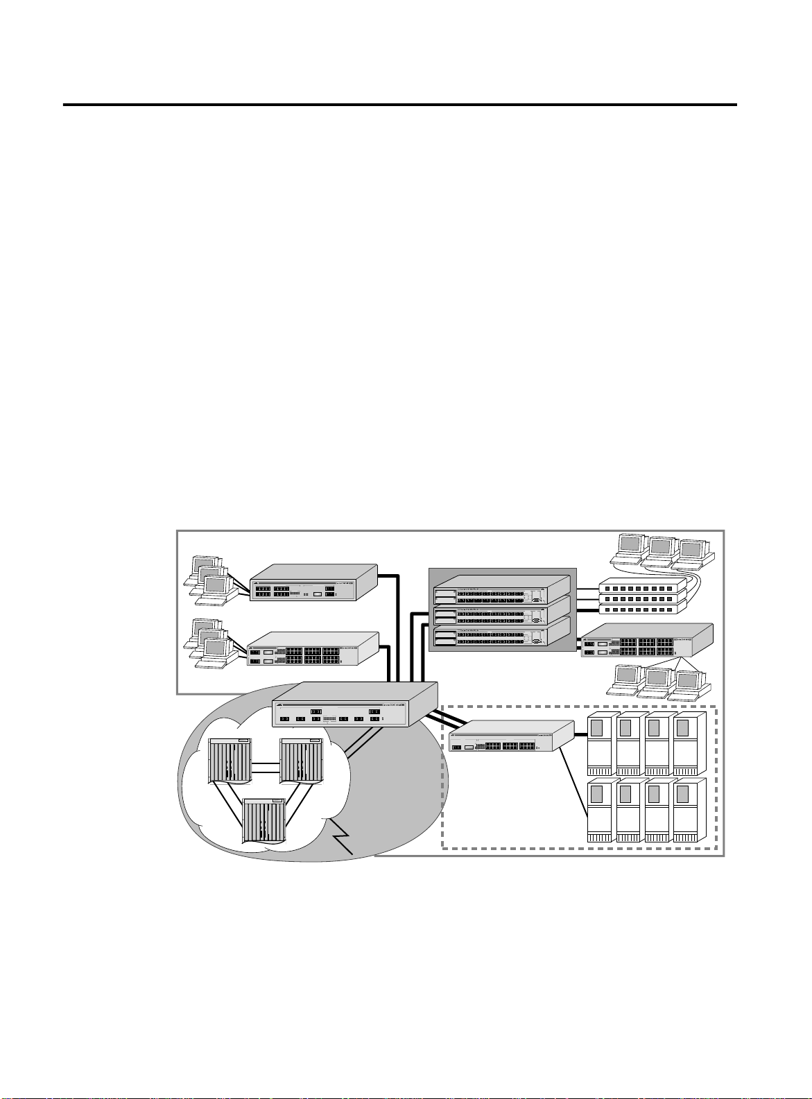
In most networks, desktop switches at the edge of the network are
aggregated with core and segment switches. An example of this
configuration is illustrated in Figure 1-1.
Intranet Switching Architecture
1234
9101112
Enterprise Desktop
49 49R
1000BASE-X
50 50R
Routers
1000BASE-X NETWORK PORTS10/100BASE-TX MDI-X NETWORK PORTS
5678
LINK/ACTIVITY
13 14 15 16
12345678
17R 17
18 17R17
ACTIVITY
910111213141516
LINK
LINKACTIVITY DISABLED
Switching
1234
5678
123456
789101112
494949R
1314 15 16 1718
49RAL
1920 21 22 2324
13 14 15 16
17 18 19 20
ACTIVITY
25 26 27 28
29 30 31 32
LINK ON
DISABLED
2526 27 28 2930
3132 33 34 3536
3738 39 49 4142
50R
4344 45 46 47485050
50RAL
37 38 39 40
41 42 43 44
1 8
234 567
10/100BASE-T ETHERNET SWITCH
WITH GIGABIT ETHERNET
18
POWER
DIAG
9101112
10/100BASE-T ETHERNET SWITCH
WITH GIGABIT ETHERNET
21 22 23 24
10/100BASE-TX
33 34 35 36
MDI-X
POWER
MGMT.
45 46 47 48
1000BASE-X NETWORK PORTS
ACTIVITY
12345678
12345678
LINK
LINK DISABLED
Core
Switching
Figure 1-1
100BASE-FX FAST ETHERNET SWITCH
100BASE-FX
L/A
L/A
L/A
L/A
L/A
A
D/C
D/C
D/C
D/C
D/C
L/A
L/A
L/A
L/A
L/A
B
D/C
D/C
D/C
D/C
D/C
100BASE-FX FAST ETHERNET SWITCH
100BASE-FX
L/A
L/A
L/A
L/A
L/A
A
D/C
D/C
D/C
D/C
D/C
L/A
L/A
L/A
L/A
L/A
B
D/C
D/C
D/C
D/C
D/C
100BASE-FX FAST ETHERNET SWITCH
100BASE-FX
L/A
L/A
L/A
L/A
L/A
A
D/C
D/C
D/C
D/C
D/C
L/A
L/A
L/A
L/A
L/A
B
D/C
D/C
D/C
D/C
D/C
STATUS
RS-232
PORT ACTIVITY
87654321
TERMINAL PORT
L/A
L/A
L/A
D/C
D/C
D/C
L/A
RXTXRXTXRXTXRXTXRXTXRXTXRXTXRXTX
LINK / ACTIVITY
FULL DUP /
HALF DUP
D/C
FAULT
161514131211109
COL
L/A
L/A
L/A
RPS
PWR
D/C
D/C
D/C
RXTXRXTXRXTXRXTXRXTXRXTXRXTXRXTX
RESET
STATUS
RS-232
PORT ACTIVITY
87654321
TERMINAL PORT
L/A
L/A
L/A
D/C
D/C
D/C
L/A
RXTXRXTXRXTXRXTXRXTXRXTXRXTXRXTX
LINK / ACTIVITY
FULL DUP /
HALF DUP
D/C
FAULT
161514131211109
COL
L/A
L/A
L/A
RPS
PWR
D/C
D/C
D/C
RXTXRXTXRXTXRXTXRXTXRXTXRXTXRXTX
RESET
STATUS
RS-232
PORT ACTIVITY
87654321
TERMINAL PORT
L/A
L/A
L/A
D/C
D/C
D/C
L/A
RXTXRXTXRXTXRXTXRXTXRXTXRXTXRXTX
LINK / ACTIVITY
FULL DUP /
HALF DUP
D/C
FAULT
161514131211109
COL
L/A
L/A
L/A
RPS
PWR
D/C
D/C
D/C
RXTXRXTXRXTXRXTXRXTXRXTXRXTXRXTX
RESET
Distributed Core
GIGABIT ETHERNET SWITCH
POWER
DIAG
Switching
1000BASE-X 10/100BASE-TX MDI-X
ACTIVITY
1234
LINK ON
DISABLED
123456
789101112
1314 15 1617 18
25R
1920 21 2223 242525
25RAL
25 25R
13 14 15 16
5678
17 18 19 20
9101112
21 22 23 24
10/100BASE-T ETHERNET SWITCH
WITH GIGABIT ETHERNET
POWER
MGMT.
Data Center
Integrated Server
Switching
Network Configuration Example
9101112
5678
1234
123456
789101112
494949R
1314 15 16 1718
49RAL
1920 21 22 2324
49 49R
13 14 15 16
ACTIVITY
25 26 27 28
LINK ON
1000BASE-X
DISABLED
2526 27 28 2930
3132 33 34 3536
3738 39 49 4142
50R
4344 45 46 47485050
50RAL
50 50R
37 38 39 40
17 18 19 20
29 30 31 32
41 42 43 44
21 22 23 24
33 34 35 36
45 46 47 48
10/100BASE-T ETHERNET SWITCH
WITH GIGABIT ETHERNET
10/100BASE-TX
MDI-X
POWER
MGMT.
ISA_2
1-6
Page 21

AT-9108, AT-8518, AT-8525, and AT-8550 User’s Guide
A high-speed core switch is used to aggregate Gigabit Ethernet links
from several Allied Telesyn Gigabit Ethernet switches and fast
Ethernet links from access routers.
In this diagram, the Gigabit switches are used for enterprise desktop
connectivity, segment switching, and server switching. The AT-8550
and AT-8525 are used for enterprise desktop connectivity; a
combination of the AT-8518 and AT-8525 is used for segment
switching; and the AT-9108 is used for server switching.
A unique feature of the Gigabit switches is that they provide full layer
3 switching or routing. By enabling core and server switches to route,
the performance penalty of traditional software-based routers can
be removed, and those routers can be used primarily for WAN and
access routing applications. At the desktop, enabling routing on
enterprise desktop switches can increase reliability by dual-homing
the switch to the backbone. In addition, routing on desktop switches
increases the efficiency of the LAN by properly handling IP multicast
packets that are destined for desktops. Segment switches that
deliver wire-speed IP routing can permit easy network migration
with no change to the existing subnet structure.
1-7
Page 22

Software Factory Defaults
Software Factory Defaults
Table 1-1 shows factory defaults for global software features.
Table 1-1
Gigabit Switches Global Factory Defaults
Item Default Setting
Serial or Telnet user account
admin
with no password and
user
with no password
Web network management Enabled
SNMP read community string
SNMP write community string
public
private
RMON Disabled
BOOTP Enabled on the default VLAN (
default
)
QoS All traffic is part of the default queue in ingress mode
QoS monitoring Automatic roving
802.1p priority Recognition enabled
802.3x flow control Enabled on Gigabit Ethernet ports
Virtual LANs One VLAN named
default
; all ports belong to the default
VLAN; the default VLAN belongs to the STPD named
802.1Q tagging All packets are untagged on the default VLAN (
default)
Spanning Tree Protocol Disabled for the switch; enabled for each port in the
STPD
Forwarding database aging period 300 seconds (5 minutes)
IP Routing Disabled
RIP Disabled
OSPF Disabled
IP multicast routing Disabled
IGMP snooping Enabled
DVMRP Disabled
GVRP Disabled
s0
1-8
Page 23

AT-9108, AT-8518, AT-8525, and AT-8550 User’s Guide
Note
Table 1-1
Gigabit Switches Global Factory Defaults
Item Default Setting
PIM-DM Disabled
IPX routing Disabled
NTP Disabled
DNS Disabled
Port mirroring Disabled
For default settings of individual software features, refer to individual
chapters in this guide.
(Continued)
1-9
Page 24

Page 25

Chapter 2
Note
Accessing the Switch
This chapter provides the following required information to begin
managing the Gigabit switch:
❑
Understanding the command syntax
❑
Line-editing commands
❑
Command history substitution
❑
Configuring the switch for management
❑
Switch management methods
❑
Configuring SNMP
❑
Checking basic connectivity
❑
Using the Simple Network Time Protocol (SNTP)
For configuration changes to be retained through a power cycle or
reboot, you must issue a SAVE command after you have made the
change. For more information on the SAVE command, refer to
Chapter 14.
2-1
Page 26

Understanding the Command Syntax
Note
This section describes the steps to take when entering a command.
Refer to the sections that follow for detailed information on using
the command-line interface.
To use the command-line interface (CLI), follow these steps:
1. When entering a command at the prompt, ensure that you have
the appropriate privilege level.
Most configuration commands require you to have the
administrator privilege level.
2. Enter the command name.
If the command does not include a parameter or values, skip
to Step 3. If the command requires more information,
continue to Step 2a.
AT-9108, AT-8518, AT-8525, and AT-8550 User’s Guide
Syntax Helper
a. If the command includes a parameter, enter the parameter
name and values.
b. The value part of the command specifies how you want the
parameter to be set. Values include numerics, strings, or
addresses, depending on the parameter.
3. After entering the complete command, press [Return].
If an asterisk (*) appears in front of the command-line prompt, it
indicates that you have outstanding configuration changes that have
not been saved. For more information on saving configuration
changes, refer to Chapter 14.
The CLI has a built-in syntax helper. If you are unsure of the complete
syntax for a particular command, enter as much of the command as
possible and press [Return]. The syntax helper provides a list of
options for the remainder of the command.
The syntax helper also provides assistance if you have entered an
incorrect command.
Command
Completion with
Syntax Helper
The switch software provides command completion if you press the
[Tab] key. If you enter a partial command, pressing the [Tab] key
posts a list of available options, and places the cursor at the end of
the command.
2-2
Page 27

AT-9108, AT-8518, AT-8525, and AT-8550 User’s Guide
Note
Abbreviated
Syntax
Command
Shortcuts
Abbreviated syntax is the shortest, most unambiguous, allowable
abbreviation of a command or parameter. Typically, this is the first
three letters of the command.
When using abbreviated syntax, you must enter enough characters to
make the command unambiguous and distinguishable to the switch.
All named components of the switch configuration must have a
unique name. Components are named using the
When you enter a command to configure a named component, you
do not need to use the keyword of the component. For example, to
create a VLAN, you must enter a unique VLAN name:
create vlan engineering
Once you have created the VLAN with a unique name, you can then
eliminate the keyword
the name to be entered. For example, instead of entering the
command
vlan
from all other commands that require
create
command.
Numerical
Ranges
Names
config vlan engineering delete port 1-3,6
you can enter the following shortcut:
config engineering delete port 1-3,6
Commands that require you to enter one or more port numbers on a
switch use the parameter
be a range of numbers, for example:
port 1-3
You can add additional port numbers to the list, separated by a
comma:
port 1-3,6,8
All named components of the switch configuration must have a
unique name. Names must begin with an alphabetical character and
are delimited by whitespace, unless enclosed in quotation marks.
<portlist>
in the syntax. A portlist can
2-3
Page 28

Understanding the Command Syntax
Symbols
You may see a variety of symbols shown as part of the command
syntax. These symbols explain how to enter the command, and you
do not type them as part of the command itself. Table 2-1
summarizes command syntax symbols.
Table 2-1
Command Syntax Symbols
Symbol Description
angle brackets < > Enclose a variable or value. You must specify the variable or value. For
example, in the syntax
config vlan <name> ipaddress <ip_address>
you must supply a VLAN name for
<ip_address>
when entering the command. Do not type the angle
<name>
and an address for
brackets.
square brackets [ ] Enclose a required value or list of required arguments. One or more
values or arguments can be specified. For example, in the syntax
disable vlan [<name> | all]
you must specify either the VLAN name for
all
when entering the command. Do not type the square brackets.
<name>
, or the keyword
vertical bar | Separates mutually exclusive items in a list, one of which must be
entered. For example, in the syntax
config snmp community [readonly | readwrite]
<string>
you must specify either the read or write community string in the
command. Do not type the vertical bar.
braces { } Enclose an optional value or a list of optional arguments. One or more
values or arguments can be specified. For example, in the syntax
show vlan {<name> | all}
you can specify either a particular VLAN or the keyword
all
. If you do
not specify an argument, the command will show all VLANs. Do not type
the braces.
2-4
Page 29

Line-Editing Keys
AT-9108, AT-8518, AT-8525, and AT-8550 User’s Guide
Table 2-2 describes the line-editing keys available using the CLI.
Table 2-2
Line-Editing Ke y
Key(s) Description
Backspace Deletes character to the left of cursor and shifts the remainder of line to
left.
Delete or
Deletes character under cursor and shifts the remainder of line to left.
[Ctrl] + D
[Ctrl] + K Deletes characters from under cursor to the end of the line.
Insert Toggles on and off. When toggled on, inserts text and shifts previous text
to right.
Left Arrow Moves cursor to left.
Right Arrow Moves cursor to right.
Home or
Moves cursor to first character in line.
[Ctrl] + A
End or [Ctrl] + E Moves cursor to last character in line.
[Ctrl] + L Clears the screen and movers the cursor to the beginning of the line.
[Ctrl] + U Clears all characters typed from the cursor to the beginning of the line.
[Ctrl] + W Deletes the previous word.
Up Arrow Displays the previous command in the command history buffer and
places cursor at end of command.
Down Arrow Displays the next command in the command history buffer and places
cursor at end of command.
2-5
Page 30

Command History
Command History
The switch software “remembers” the last 49 commands you enter.
You can display a list of these commands by using the following
command:
history
2-6
Page 31

Common Commands
AT-9108, AT-8518, AT-8525, and AT-8550 User’s Guide
Table 2-3 describes common commands used to manage the switch.
Commands specific to a particular feature are described in the other
chapters of this guide.
Table 2-3
Common Commands
Command Description
create account [admin | user]
<username> {encrypted} {<password>}
Creates a user account. The
should only be used by the switch to generate an
ASCII configuration (using the
configuration
command), and parsing a
encrypted
upload
option
switch-generated configuration (using the
download configuration
command).
create vlan <name> Creates a VLAN with the given name.
config account <username> {encrypted}
{<password>}
Configures a user account password. Passwords
must have a minimum of 4 characters and can have
a maximum of 12 characters. User names and
passwords are case-sensitive.
config banner Configures the banner string. You can enter up to
24 rows of 80-column text that is displayed before
the login prompt of each session. Press [Return] at
the beginning of a line to terminate the command
and apply the banner. To clear the banner, press
[Return] at the beginning of the first line.
config ports <portlist> auto off {speed
[10 | 100]} duplex [half | full]
Manually configures the port speed and duplex
setting of one or more ports on a switch.
config time <date> <time> Configures the system date and time. The format is
as follows:
mm/dd/yyyy hh:mm:ss
The time uses a 24-hour clock format. You cannot
set the year past 2023.
2-7
Page 32

Common Commands
Table 2-3
Common Commands
(Continued)
Command Description
config timezone <gmt_offset> {autodst |
noautodst}
Configures the time zone information to the
configured offset from GMT time. The format of
gmt_offset
is +/- minutes from GMT time.
Specify:
❑
autodst — Enables automatic Daylight
Savings Time change
❑
nosautodst — Disables automatic Daylight
Savings Time change.
autodst
.
config vlan <name> ipaddress
<ip_address> {<mask>}
The default setting is
Configures an IP address and subnet mask for a
VLAN.
enable bootp vlan [<name> | all] Enables BootP for one or more VLANs.
enable idletimeout Enables a timer that disconnects all sessions (both
Telnet and console) after 20 minutes of inactivity.
The default setting is disabled.
enable license [basic_L3 | advanced_L3]
<license_key>
Enables a particular software feature license. Specify
<license_key>
as an integer. This command is
available only on the AT-8550 and AT-8525.
The command
unconfig switch all
does not
clear licensing information. This feature cannot be
disabled once the license is enabled on the switch.
enable telnet Enables Telnet access to the switch.
help Displays a command summary list.
history Displays the previous 49 commands entered on the
switch.
clear session <number> Terminates a Telnet session from the switch.
disable bootp vlan [<name> | all] Disables BootP for one or more VLANs.
disable idletimeout Disables the timer that disconnects all sessions.
Once disabled, console sessions remain open until
the switch is rebooted or you logoff. Telnet sessions
remain open until you close the Telnet client.
disable port <portlist> Disables a port on the switch.
disable telnet Disables Telnet access to the switch.
delete account <username> Deletes a user account.
delete vlan <name> Deletes a VLAN.
2-8
Page 33

AT-9108, AT-8518, AT-8525, and AT-8550 User’s Guide
Table 2-3
Common Commands
(Continued)
Command Description
unconfig switch {all} Resets all switch parameters (with the exception of
defined user accounts, and date and time
information) to the factory defaults. If you specify
the keyword
all
, the user account information is
reset as well.
show banner Displays the user-configured banner.
2-9
Page 34

Configuring Management Access
Configuring Management Access
The switch software supports the following two level levels of
management:
❑
User
❑
Administrator
A user-level account has viewing access to all manageable
parameters, with the exception of the following:
❑
User account database
❑
SNMP community strings
A user-level account can use the
ping
command to test device
reachability, and change the password assigned to the account
name. If you have logged on with user capabilities, the commandline prompt ends with a (>) sign. For example:
8550:2>
An administrator-level account can view and change all switch
parameters. It can also add and delete users, and change the
password associated with any account name. The administrator can
disconnect a management session that has been established by way
of a Telnet connection. If this happens, the user logged on by way of
the Telnet connection is notified that the session has been
terminated.
If you have logged on with administrator capabilities, the commandline prompt ends with a (#) sign. For example:
8550:18#
The prompt text is taken from the SNMP
sysname
setting. The
number that follows the colon indicates the sequential
line/command number.
2-10
If an asterisk (*) appears in front of the command-line prompt, it
indicates that you have outstanding configuration changes that
have not been saved. For example:
*8550:19#
Note
For more information on saving configuration changes, refer to
Chapter 14.
Page 35

AT-9108, AT-8518, AT-8525, and AT-8550 User’s Guide
Note
Default Accounts
By default, the switch is configured with two accounts, as shown in
Table 2-4.
Table 2-4
Default Accounts
Account Name Access Level
admin This user can access and change all manageable parameters. The admin
account cannot be deleted.
user This user can view (but not change) all manageable parameters, with the
following exceptions:
❑
This user cannot view the user account database.
❑
This user cannot view the SNMP community strings.
Changing the Default Password.
Default accounts do not have
passwords assigned to them. Passwords must have a minimum of 4
characters and can have a maximum of 12 characters.
User names and passwords are case-sensitive.
To add a password to the default admin account, follow these
steps:
1. Log in to the switch using the name
admin
.
2. At the password prompt, press [Return].
3. Add a default admin password by typing the following:
config account admin
4. Enter the new password at the prompt.
5. Re-enter the new password at the prompt.
To add a password to the default user account, follow these
steps:
1. Log in to the switch using the name
admin
.
2. At the password prompt, press [Return], or enter the password
that you have configured for the
admin
account.
3. Add a default user password by typing the following:
config account user
4. Enter the new password at the prompt.
5. Re-enter the new password at the prompt.
2-11
Page 36

Configuring Management Access
Note
If you forget your password while logged out of the command-line
interface, contact your local technical support representative, who
will advise on your next course of action.
Creating a
Management
Account
The switch can have a total of 16 management accounts. You can use
the default names (
admin
and
user
), or you can create new names
and passwords for the accounts. Passwords must have a minimum of
4 characters and can have a maximum of 12 characters.
To create a new account, follow these steps:
1. Log in to the switch as
admin
.
2. At the password prompt, press [Return], or enter the password
that you have configured for the
admin
account.
3. Add a new user by using the following command:
create account [admin | user] <username>
{encrypted}
4. Enter the password at the prompt.
5. Re-enter the password at the prompt.
Viewing Accounts.
To view the accounts that have been created,
you must have administrator privileges. Use the following command
to see the accounts:
show accounts
Deleting an Account.
To delete a account, you must have
administrator privileges. Use the following command to delete an
account:
delete account <username>
Note
The account name admin cannot be deleted.
2-12
Page 37

Methods of Managing the Switch
Note
You can manage the switch using the following methods:
❑
Access the CLI by connecting a terminal (or workstation with
terminal-emulation software) to the console port.
❑
Access the CLI over a TCP/IP network using a Telnet
connection.
❑
Use an SNMP Network Manager over a network running the IP
protocol.
The switch can support up to multiple user sessions concurrently, as
follows:
❑
One console session
❑
Eight Telnet sessions
AT-9108, AT-8518, AT-8525, and AT-8550 User’s Guide
Using the
Console Interface
The CLI built into the switch is accessible by way of the 9-pin, RS-232
port labeled
console
, located on the back of the Switch.
For more information on the console port pinouts, refer to the switch
hardware installation guide.
Once the connection is established, you will see the switch prompt
and you may log in.
2-13
Page 38

Using Telnet
Using Telnet
Any workstation with a Telnet facility should be able to
communicate with the switch over a TCP/IP network.
Up to eight active Telnet sessions can access the switch concurrently.
idle timeouts
If
after 20 minutes of inactivity. If a connection to a Telnet session is
lost inadvertently, the switch terminates the session within two
hours.
Before you can start a Telnet session, you must set up the IP
parameters described in the section “Configuring Switch IP
Parameters,” later in this chapter. Telnet is enabled by default.
To open the Telnet session, you must specify the IP address of the
device that you want to manage. Check the user manual supplied
with the Telnet facility if you are unsure of how to do this.
Once the connection is established, you will see the switch prompt
and you may log in.
are enabled, the Telnet connection will time out
Connecting to
Another Host
Using Telnet
Configuring
Switch IP
Parameters
You can Telnet from the current CLI session to another host using the
following command:
telnet [<ipaddress> | <hostname>]
{<port_number>}
If the TCP port number is not specified, the Telnet session defaults to
port 23. Only VT100 emulation is supported.
To manage the switch by way of a Telnet connection or by using an
SNMP Network Manager, you must first configure the switch IP
parameters.
Using a BootP Server.
Protocol (BootP) server set up correctly on your network, you must
add the following information to the BootP server:
❑
Switch Media Access Control (MAC) address
❑
IP address
❑
Subnet address mask (optional)
If you are using IP and you have a Bootstrap
2-14
The switch MAC address is found on the rear label of the switch.
Once this is done, the IP address and subnetwork mask for the switch
will be downloaded automatically. You can then start managing the
switch without further configuration.
Page 39

AT-9108, AT-8518, AT-8525, and AT-8550 User’s Guide
Note
Note
You can enable BootP on a per-VLAN basis by using the following
command:
enable bootp vlan [<name> | all]
By default, BootP is enabled on the
default
VLAN.
If you configure the switch to use BootP, the switch IP address is not
retained through a power cycle, even if the configuration has been
saved. To retain the IP address through a power cycle, you must
configure the IP address of the VLAN using the command-line
interface, Telnet, or Web interface.
All VLANs within a switch that are configured to use BootP to get
their IP address use the same MAC address. Therefore, if you are
using BootP relay through a router, the BootP server must be capable
of differentiating its relay based on the gateway portion of the BootP
packet.
For more information on DHCP/BootP relay, refer to Chapter 8.
Manually Configuring the IP Settings.
If you are using IP without a
BootP server, you must enter the IP parameters for the switch in
order for the SNMP Network Manager, Telnet software, or Web
interface to communicate with the device. To assign IP parameters to
the switch, you must do the following:
❑
Log in to the switch with administrator privileges.
❑
Assign an IP address and subnetwork mask to a VLAN.
The switch comes configured with a default VLAN named
default
. To use Telnet or an SNMP Network Manager, you must
have at least one VLAN on the switch, and it must be assigned
an IP address and subnetwork mask. IP addresses are always
assigned to a VLAN. The switch can be assigned multiple IP
addresses.
For information on creating and configuring VLANs, refer to Chapter
4.
2-15
Page 40

Using Telnet
To configure the IP settings manually, perform the following
steps:
1. Connect a terminal or workstation running terminal-emulation
software to the console port.
2. At your terminal, press [Return] one or more times until you see
the login prompt.
3. At the login prompt, enter your user name and password. Note
that they are both case-sensitive. Ensure that you have entered a
user name and password with administrator privileges.
– If you are logging in for the first time, use the default user
name
admin
to log in with administrator privileges. For
example:
login: admin
– Administrator capabilities enable you to access all switch
functions. The default user names have no passwords
assigned.
– If you have been assigned a user name and password with
administrator privileges, enter them at the login prompt.
4. At the password prompt, enter the password and press [Return].
When you have successfully logged in to the switch, the
command-line prompt displays the name of the switch in its
prompt.
5. Assign an IP address and subnetwork mask for the default VLAN
by using the following command:
config vlan <name> ipaddress <ipaddress>
{<subnet_mask>}
For example:
config vlan default ipaddress 123.45.67.8
255.255.255.0
Your changes take effect immediately.
2-16
Page 41

AT-9108, AT-8518, AT-8525, and AT-8550 User’s Guide
Note
Note
As a general rule, when configuring any IP addresses for the switch,
you can express a subnet mask by using dotted decimal notation, or
by using classless inter-domain routing notation (CIDR). CIDR uses a
forward slash plus the number of bits in the subnet mask. Using CIDR
notation, the command identical to the one above would be:
config vlan default ipaddress 123.45.67.8 / 24
6. Configure the default route for the switch using the following
command:
config iproute add default <ipaddress>
{<metric>}
For example:
config iproute add default 123.45.67.1
7. Save your configuration changes so that they will be in effect after
the next switch reboot, by typing
Disconnecting a
Telnet Session
save
For more information on saving configuration changes, refer to
Chapter 14.
8. When you are finished using the facility, log out of the switch by
typing
logout or quit
An administrator-level account can disconnect a management
session that has been established by way of a Telnet connection. If
this happens, the user logged in by way of the Telnet connection is
notified that the session has been terminated.
To terminate a Telnet session, follow these steps:
1. Log in to the switch with administrator privileges.
2. Determine the session number of the session you want to
terminate by using the following command:
show session
3. Terminate the session by using the following command:
clear session <session_number>
2-17
Page 42

Using Telnet
Disabling Telnet
Access
By default, Telnet services are enabled on the switch. You can choose
to disable Telnet by entering
disable telnet
To re-enable Telnet on the switch, at the console port enter
enable telnet
You must be logged in as an administrator to enable or disable
Telnet.
2-18
Page 43

IP Host Configuration Commands
Table 2-5 describes the commands that are used to configure IP
settings on the switch.
AT-9108, AT-8518, AT-8525, and AT-8550 User’s Guide
Table 2-5
IP Host Configuration Commands
Command Description
config iparp add <ipaddress>
<mac_address>
Adds a permanent entry to the Address Resolution
Protocol (ARP) table. Specify the IP address and
MAC address of the entry.
config iparp delete <ipaddress> Deletes an entry from the ARP table. Specify the IP
address of the entry.
clear iparp {<ipaddress> | vlan <name>} Removes dynamic entries in the IP ARP table.
Permanent IP ARP entries are not affected.
config iproute add <ipaddress> <mask>
<gateway> {<metric>}
Adds a static address to the routing table. Use a
value of 255.255.255.255 for
mask
to indicate a host
entry.
config iproute delete <ipaddress>
Deletes a static address from the routing table.
<mask> <gateway>
config iproute add default <gateway>
{<metric>}
Adds a default gateway to the routing table. A
default gateway must be located on a configured IP
interface. If no metric is specified, the default metric
of 1 is used.
config iproute delete default <gateway> Deletes a default gateway from the routing table.
show ipconfig {vlan <name>} Displays configuration information for one or all
VLANs.
show ipstats {vlan <name>} Displays IP statistics for the CPU of the switch or for
a particular VLAN.
show iproute {priority | vlan <name> |
Displays the contents of the IP routing table.
permanent | <ipaddress> <mask>}
show iparp {<ipaddress | vlan <name> |
permanent}
Displays the IP ARP table. You can filter the display
by IP address, VLAN, or permanent entries.
2-19
Page 44

Domain Name Service Client Services
Domain Name Servic e Cl ien t Servi ce s
The Domain Name Service (DNS) client in ExtremeWare augments
the following commands to allow them to accept either IP addresses
or host names:
❑
telnet
❑
download [image | configuration | bootrom]
❑
upload configuration
❑
ping
❑
traceroute
In addition, the
nslookup
utility can be used to return the IP
address of a hostname.
Table 2-6 describes the commands used to configure DNS.
Table 2-6
DNS Commands
Command Description
config dns-client default-domain
<domain_name>
Configures the domain that the DNS client uses if a
fully qualified domain name is not entered. For
example, if the default domain is configured to be
foo.com
, executing
ping bar
searches for
bar.foo.com.
config dns-client add <ipaddress> Adds a DNS name server(s) to the available server
list for the DNS client. Up to three name servers can
be configured.
config dns-client delete <ipaddress> Removes a DNS server.
nslookup <hostname> Displays the IP address of the requested host.
show dns-client Displays the DNS configuration.
2-20
Page 45

AT-9108, AT-8518, AT-8525, and AT-8550 User’s Guide
Using the Simple Network Time Protocol
The switch software supports the client portion of the Simple
Network Time Protocol (SNTP) Version 3 based on RFC1769. SNTP
can be used by the switch to update and synchronize its internal
clock from a Network Time Protocol (NTP) server. When enabled, the
switch sends out a periodic query to the indicated NTP server, or the
switch listens to broadcast NTP updates. In addition, the switch
supports the configured setting for Greenwich Mean time (GMT)
offset and the use of Daylight Savings Time. These features have
been tested for year 2000 compliance.
Configuring and
Using SNTP
GMT
Offset in
Hours
GMT
Offset in
Minutes
To use SNTP, follow these steps:
1. Identify the host(s) that are configured as NTP server(s).
Additionally, identify the preferred method for obtaining NTP
updates. The options are for the NTP server to send out
broadcasts, or for switches using NTP to query the NTP server(s)
directly. A combination of both methods is possible. You must
identify the method that should be used for the switch being
configured.
2. Configure the Greenwich Mean Time (GMT) offset and Daylight
Savings Time preference. NTP updates are distributed using GMT
time. To properly display the local time in logs and other
timestamp information, the switch should be configured with the
appropriate offset to GMT based on geographical location.
Table 2-7 describes GMT offsets.
Table 2-7
Common Time Zone
References
Greenwich Mean Time Offsets
Cities
+0:00 +0 GMT - Greenwich Mean
UT or UTC - Universal
(Coordinated)
WET - Western European
-1:00 -60 WAT - West Africa Azores, Cape Verde Islands
-2:00 -120 AT - Azores
-3:00 -180 Brasilia, Brazil ; Buenos Aires,
-4:00 -240 AST - Atlantic Standard Caracas ; La Paz
London, England; Dublin, Ireland;
Edinburgh, Scotland ; Lisbon,
Portugal; Reykjavik, Iceland ;
Casablanca, Morocco
Argentina; Georgetown, Guyana;
2-21
Page 46

Using the Simple Network Time Protocol
(Continued)
Cities
GMT
Offset in
Hours
Table 2-7
GMT
Offset in
Minutes
Greenwich Mean Time Offsets
Common Time Zone
References
-5:00 -300 EST - Eastern Standard Bogota, Columbia; Lima, Peru; New
York, NY, Trevor City, MI USA
-6:00 -360 CST - Central Standard Mexico City, Mexico
Saskatchewan, Canada
-7:00 -420 MST - Mountain Standard
-8:00 -480 PST - Pacific Standard Los Angeles, CA, Cupertino, CA,
Seattle, WA USA
-9:00 -540 YST - Yukon Standard
-10:00 -600 AHST - Alaska-Hawaii
Standard
CAT - Central Alaska
HST - Hawaii Standard
-11:00 -660 NT - Nome
-12:00 -720 IDLW - International Date Line
West
+1:00 +60 CET - Central European
FWT - French Winter
MET - Middle European
MEWT - Middle European
Winter
SWT - Swedish Winter
+2:00 +120 EET - Eastern European,
Russia Zone 1
Paris, France ; Berlin, Germany;
Amsterdam, The Netherlands ;
Brussels, Belgium ; Vienna, Austria ;
Madrid, Spain; Rome, Italy; Bern,
Switzerland; Stockholm, Sweden;
Oslo, Norway
Athens, Greece; Helsinki, Finland;
Istanbul, Turkey; Jerusalem, Israel;
Harare, Zimbabwe
+3:00 +180 BT - Baghdad, Russia Zone 2 Kuwait; Nairobi, Kenya; Riyadh, Saudi
Arabia; Moscow, Russia; Tehran, Iran
+4:00 +240 ZP4 - Russia Zone 3 Abu Dhabi, UAE; Muscat; Tblisi;
Volgograd; Kabul
+5:00 +300 ZP5 - Russia Zone 4
+5:30 +330 IST – India Standard Time New Delhi, Pune, Allahabad, India
+6:00 +360 ZP6 - Russia Zone 5
+7:00 +420 WAST - West Australian
Standard
2-22
Page 47

AT-9108, AT-8518, AT-8525, and AT-8550 User’s Guide
Greenwich Mean Time Offsets
Common Time Zone
References
GMT
Offset in
Hours
Table 2-7
GMT
Offset in
Minutes
+8:00 +480 CCT - China Coast, Russia
Zone 7
+9:00 +540 JST - Japan Standard, Russia
Zone 8
+10:00 +600 EAST - East Australian
Standard
GST - Guam Standard
Russia Zone 9
+11:00 +660
+12:00 +720 IDLE - International Date Line
East
NZST - New Zealand Standard
NZT - New Zealand
(Continued)
Cities
Wellington, New Zealand; Fiji,
Marshall Islands
The command syntax to configure GMT offset and usage of
Daylight Savings is as follows:
config timezone <GMT_offset> {autodst |
noautodst}
The GMT_OFFSET is in +/- minutes from the GMT time.
Automatic Daylight Savings Time (DST) changes can be
enabled or disabled. The default setting is enabled.
3. Enable the SNTP client using the following command:
enable sntp-client
Once enabled, the switch sends out a periodic query to the
NTP servers defined later (if configured) or listens to broadcast
NTP updates from the network. The network time information
is automatically saved into the on-board real-time clock.
4. If you would like this switch to use a directed query to the NTP
server, configure the switch to use the NTP server(s). If the switch
listens to NTP broadcasts, skip this step. To configure the switch to
use a directed query, use the following command:
config sntp-client [primary | secondary]
server [<ip_address> | <hostname>]
2-23
Page 48

Using the Simple Network Time Protocol
5. Optionally, the interval for which the SNTP client updates the real-
NTP queries are first sent to the primary server. If the primary
server does not respond within 1 second, or if it is not
synchronized, the switch queries the secondary server (if one
is configured). If the switch cannot obtain the time, it restarts
the query process. Otherwise, the switch waits for the
client update interval
before querying again.
sntp-
time clock of the switch can be changed using the following
command:
config sntp-client update-interval <seconds>
The default
sntp-client update-interval
value is 64
seconds.
6. You can verify the configuration using the following commands:
show sntp-client
This command provides configuration and statistics associated with
SNTP and its connectivity to the NTP server.
show switch
This command indicates the GMT offset, Daylight Savings Time, and
the current local time.
2-24
Page 49

AT-9108, AT-8518, AT-8525, and AT-8550 User’s Guide
SNTP
Table 2-8 describes SNTP configuration commands.
Configuration
Commands
Table 2-8
Command Description
enable sntp-client Enables Simple Network Time Protocol (SNTP) client
disable sntp-client Disables SNTP client functions.
config sntp-client [primary | secondary]
server [<ipaddress> | <host_name>]
config sntp-client update-interval
<seconds>
SNTP Configuration Commands
functions.
Configures an NTP server for the switch to obtain
time information. Queries are first sent to the
primary server. If the primary server does not
respond within 1 second, or if it is not synchronized,
the switch queries the second server.
Configures the interval between polling for time
information from SNTP servers. The default setting
is 64 seconds.
show sntp-client Displays configuration and statistics for the SNTP
client.
SNTP Example
In this example, the switch queries a specific NTP server and a
backup NTP server. The switch is located in Cupertino, CA, and an
update occurs every 20 minutes. The commands to configure the
switch are as follows:
config timezone -240 autodst
enable sntp-client
config sntp-client primary server 10.0.1.1
config sntp-client secondary server 10.0.1.2
2-25
Page 50

Using SNMP
Using SNMP
Any Network Manager running the Simple Network Management
Protocol (SNMP) can manage the switch, provided the Management
Information Base (MIB) is installed correctly on the management
station. Each Network Manager provides its own user interface to the
management facilities.
The following sections describe how to get started if you want to use
an SNMP manager. It assumes you are already familiar with SNMP
management. If not, refer to the following publication:
Accessing Switch
Agents
Supported MIBs
Configuring
SNMP Settings
The Simple Book
by Marshall T. Rose
ISBN 0-13-8121611-9
Published by Prentice Hall
To have access to the SNMP agent residing in the switch, at least one
VLAN must have an IP address assigned to it.
For more information on assigning IP addresses, refer to Table 2-3.
Any Network Manager running SNMP can manage the switch,
provided the MIB is installed correctly on the management station. In
addition to private MIBs, the switch supports the standard MIBs
listed in Appendix A.
The following SNMP parameters can be configured on the switch:
❑
Authorized trap receivers
be one or more network management stations on your
network. The switch sends SNMP traps to all trap receivers.
You can have a maximum of six trap receivers configured for
each switch. Entries in this list can be created, modified, and
deleted using the RMON2 trapDestTable MIB variable, as
described in RFC 2021.
Note
— An authorized trap receiver can
2-26
❑
Authorized managers
either a single network management station, or a range of
addresses (for example, a complete subnet) specified by a
prefix and a mask. The switch can have a maximum of eight
authorized managers.
— An authorized manager can be
Page 51

AT-9108, AT-8518, AT-8525, and AT-8550 User’s Guide
❑
Community strings
— The community strings allow a simple
method of authentication between the switch and the remote
Network Manager. There are two types of community strings
on the switch. Read community strings provide read-only
access to the switch. The default read-only community string
public
is
. Read-write community strings provide read and
write access to the switch. The default read-write community
string is
private
. A total of eight community strings can be
configured on the switch. The community string for all
authorized trap receivers must be configured on the switch for
the trap receiver to receive switch-generated traps. SNMP
community strings can contain up to 126 characters.
❑
System contact
(optional) — The system contact is a text field
that enables you to enter the name of the person(s)
responsible for managing the switch.
❑
System name
— The system name is the name that you have
assigned to this switch. The default name is the model name
of the switch (for example, Summit1).
❑
System location
(optional) — Using the system location field,
you can enter an optional location for this switch.
Table 2-9 describes SNMP configuration commands.
Table 2-9
SNMP Configuration Commands
Command Description
enable snmp access Turns on SNMP support for the switch.
enable snmp traps Turns on SNMP trap support.
config snmp add <ipaddress> {<mask>} Adds the IP address of an SNMP management
station to the access list. Up to 32 addresses can be
specified.
config snmp add trapreceiver
<ipaddress> community <string>
Adds the IP address of a specified trap receiver. The
IP address can be a unicast, multicast, or broadcast.
A maximum of six trap receivers is allowed.
config snmp community [readonly |
readwrite] <string>
Adds an SNMP read or read/write community string.
The default
public
string is
readonly
. The default
private
. Each community string can have
community string is
readwrite
community
a maximum of 126 characters, and can be enclosed
by double quotation marks.
2-27
Page 52

Using SNMP
Table 2-9
SNMP Configuration Commands
(Continued)
Command Description
config snmp delete [<ipaddress>
{<mask>} | all]
Deletes the IP address of a specified SNMP
management station or all SNMP management
stations. If you delete all addresses, any machine
can have SNMP management access to the switch.
config snmp delete trapreceiver
[<ip_address> community <string> | all]
Deletes the IP address of a specified trap receiver or
all authorized trap receivers.
config snmp syscontact <string> Configures the name of the system contact. A
maximum of 255 characters is allowed.
config snmp sysname <string> Configures the name of the switch. A maximum of
32 characters is allowed. The default sysname is the
model name of the device (for example,
Summit1)
. The
sysname
appears in the switch
prompt.
config snmp syslocation <string> Configures the location of the switch. A maximum
of 255 characters is allowed.
Displaying
SNMP Settings
To display the SNMP settings configured on the switch, enter the
following command:
show management
This command displays the following information:
❑
Enable/disable state for Telnet, SNMP, and Web access
❑
SNMP community strings
❑
Authorized SNMP station list
❑
SNMP trap receiver list
❑
RMON polling configuration
❑
Login statistics
2-28
Page 53

AT-9108, AT-8518, AT-8525, and AT-8550 User’s Guide
Resetting and
To reset and disable SNMP settings, use the commands in Table 2-10.
Disabling SNMP
Table 2-10
Command Description
disable snmp access Disables SNMP on the switch. Disabling SNMP access does not
disable snmp traps Prevents SNMP traps from being sent from the switch. Does
unconfig management Restores default values to all SNMP-related entries.
SNMP Reset and Disable Commands
affect the SNMP configuration (for example, community
strings).
not clear the SNMP trap receivers that have been configured.
2-29
Page 54

Checking Basic Connectivity
Checking Basic Connectivity
The switch offers the following commands for checking basic
connectivity:
❑
ping
❑
traceroute
Ping
ping
The
Protocol (ICMP) echo messages to a remote IP device. The
command is available for both the user and administrator privilege
level.
The
ping {continuous} {size <n>} [<ip_address> |
<hostname>]
Options for the ping command are described in Table 2-11.
Parameter Description
continuous
size <n>
<ipaddress Specifies the IP address of the host.
command enables you to send Internet Control Message
ping
command syntax is
Table 2-11
Specifies ICMP echo messages to be sent
continuously. This option can be interrupted by
pressing any key.
Specifies the size of the packet.
Ping Command Parameters
ping
2-30
Traceroute
<hostname> Specifies the name of the host. To use the
hostname
ping
If a
until interrupted. Press any key to interrupt a
The
between the switch and a destination endstation. The
command syntax is
traceroute [<ip_address> | <hostname>]
where:
request fails, the switch continues to send
traceroute
❑
ip_address
❑
hostname
use the hostname, you must first configure DNS.
command enables you to trace the routed path
is the IP address of the destination endstation.
is the hostname of the destination endstation. To
, you must first configure DNS.
ping
messages
ping
request.
traceroute
Page 55

Chapter 3
Note
Configuring Switch Ports
This chapter describes how to configure ports on the switch. .
Ports on the switch can be configured in the following ways:
❑
Enabling and disabling individual ports
❑
Configuring the port speed (Fast Ethernet ports only)
❑
Configuring half- or full-duplex mode
❑
Creating load-sharing groups on multiple ports
❑
Changing the Quality or Service (QoS) setting for individual
ports
For more information on QoS, refer to Chapter 7.
3-1
Page 56

Enabling and Disabling Ports
Enabling and Disabling Ports
By default, all ports are enabled. To enable or disable one or more
ports, use the following command:
[enable | disable] port <portlist>
For example, to disable ports 3, 5, and 12 through 15 , enter the
following:
disable port 3,5,12-15
Even though a port is disabled, the link remains enabled for
diagnostic purposes.
3-2
Page 57

AT-9108, AT-8518, AT-8525, and AT-8550 User’s Guide
Configuring Port Speed and Duplex Setting
By default, the switch is configured to use autonegotiation to
determine the port speed and duplex setting for each port. You can
select to manually configure the duplex setting and the speed of
10/100 Mbps ports, and you can manually configure the duplex
setting on Gigabit Ethernet ports.
Fast Ethernet ports can connect to either 10Base-T or 100Base-T
networks. By default, the ports autonegotiate port speed. You can
also configure each port for a particular speed (either 10 Mbps or 100
Mbps).
Gigabit Ethernet ports are statically set to 1 Gbps, and their speed
cannot be modified.
All ports on the switch can be configured for half-duplex or fullduplex operation. By default, the ports autonegotiate the duplex
setting.
Turning Off
Autonegotiation
for a Gigabit
Ethernet Port
To configure port speed and duplex setting, use the following
command:
config ports <portlist> auto off {speed [10 |
100]} duplex [half | full]
To configure the switch to autonegotiate, use the following
command:
config ports <portlist> auto on
Flow control is supported only on Gigabit Ethernet ports. It is
enabled or disabled as part of autonegotiation. If autonegotiation is
set to off, flow control is disabled. When autonegotiation is turned
on, flow control is enabled.
In certain interoperability situations, it is necessary to turn
autonegotiation off on a Gigabit Ethernet port. Even though a
Gigabit Ethernet port runs only at full duplex and gigabit speeds, the
command that turns off autonegotiation must still include the
duplex setting.
The following example turns autonegotiation off for port 4 (a Gigabit
Ethernet port);
config ports 4 auto off duplex full
3-3
Page 58

Port Commands
Port Commands
Table 3-1 describes the switch port commands.
Table 3-1
Port Commands
Command Description
enable learning port <portlist> Enables MAC address learning on one or more ports. The
default setting is enabled.
enable port <portlist> Enables a port.
enable sharing <master_port>
grouping <portlist>
Defines a load-sharing group of ports. The ports specified
portlist
in <
> are grouped to the master port.
enable smartredundancy <portlist> Enables the smart redundancy feature on the redundant
Gigabit Ethernet port. When the Smart Redundancy
feature is enabled, the switch always uses the primary
link when the primary link is available. The default setting
is enabled.
config ports <portlist> auto on Enables autonegotiation for the particular port type;
802.3u for 10/100 Mbps ports or 802.3z for Gigabit
Ethernet ports.
config ports <portlist> auto off
{speed [10 | 100]} duplex [half | full]
Changes the configuration of a group of ports. Specify
the following:
❑
auto off
— The port will not autonegotiate the
settings.
❑
speed
— The speed of the port (for 10/100 Mbps
ports only).
❑
duplex
— The duplex setting (half- or full-duplex).
config ports <portlist> displaystring <string>
Configures a user-defined string for a port. The string is
displayed in certain
show port all info
show
commands (for example,
). The string can be up to 16
characters.
config ports <portlist> qosprofile
<qosname>
unconfig ports <portlist> display-
Configures one or more ports to use a particular QoS
profile.
Clears the user-defined display string from a port.
string <string>
disable learning port <portlist> Disables MAC address learning on one or more ports for
security purposes. If MAC address learning is disabled,
only broadcast traffic, EDP traffic, and packets destined
to a permanent MAC address matching that port
number, are forwarded. The default setting is enabled.
3-4
Page 59

AT-9108, AT-8518, AT-8525, and AT-8550 User’s Guide
Table 3-1
Port Commands
(Continued)
Command Description
disable port <portlist> Disables a port. Even when disabled, the link is available
for diagnostic purposes.
disable sharing <master_port> Disables a load-sharing group of ports.
disable smartredundancy
<portlist>
Disables the smart redundancy feature. If the feature is
disabled, the switch changes the active link only when
the current active link becomes inoperable.
restart port <portlist> Resets autonegotiation for one or more ports by
resetting the physical link.
show ports {<portlist>} collisions Displays real-time collision statistics.
show ports {<portlist>}
Displays the port configuration.
configuration
show ports {<portlist>} info Displays detailed system-related information.
show ports {<portlist>} packet Displays a histogram of packet statistics.
show ports {<portlist>} qosmonitor Displays real-time QoS statistics. For more information on
QoS, refer to Chapter 7.
show ports {<portlist>} rxerrors Displays real-time receive error statistics. For more
information on error statistics, refer to Chapter 13.
show ports {<portlist>} stats Displays real-time port statistics. For more information
on port statistics, refer to Chapter 13.
show ports {<portlist>} txerrors Displays real-time transmit error statistics. For more
information on error statistics, refer to Chapter 13.
show ports {<portlist>} utilization Displays real-time port utilization information. Use the
[Spacebar] to toggle between packet, byte, and
bandwidth utilization information.
3-5
Page 60

Load Sharing on the Switch
Load Sharing on the Switch
Load sharing with switches allows you to increase bandwidth and
resilience between switches by using a group of ports to carry traffic
in parallel between switches. The sharing algorithm allows the
switch to use multiple ports as a single logical port. For example,
VLANs see the load-sharing group as a single logical port. The
algorithm also guarantees packet sequencing between clients.
If a port in a load-sharing group fails, traffic is redistributed to the
remaining ports in the load-sharing group. If the failed port becomes
active again, traffic is redistributed to include that port.
Load sharing must be enabled on both ends of the link, or a network
loop will result.
Load sharing is most useful in cases where the traffic transmitted
from the switch to the load-sharing group is sourced from an equal
or greater number of ports on the switch. For example, traffic
transmitted to a two-port load-sharing group should originate from
a minimum of two other ports on the same switch.
Note
Configuring Load
Sharing
This feature is supported between Allied Telesyn Gigabit Ethernet
switches only, but may be compatible with third-party “trunking” or
sharing algorithms. Check with an Allied Telesyn’s Technical Support
department for more information.
To set up the switch to load share among ports, you must create a
load-sharing group of ports. Load-sharing groups are defined
according to the following rules:
❑
Ports on the switch are divided into groups of two or four.
❑
Ports in a load-sharing group must be contiguous.
❑
Follow the outlined boxes in Table 3-4 through Table 3-5 to
determine the valid port combinations.
❑
The first port in the load-sharing group is configured to be the
“master” logical port. This is the reference port used in
configuration commands. It can be thought of as the logical
port representing the entire port group.
3-6
Page 61

AT-9108, AT-8518, AT-8525, and AT-8550 User’s Guide
Table 3-2, Table 3-3, Table 3-4 and Table 3-5 show the possible load-
sharing port group combinations for the AT-9108, AT-8518, AT-8525,
and AT-8550, respectively.
Load-Sharing Group
4-port groups
2-port groups
Load-Sharing Group
4-port groups
2-port groups
Load-Sharing Group
Table 3-2
Port Combinations for the AT-9108
12
3 4 5 6 78
x x x x
x x x x x x
Table 3-3
Port Combinations for the AT-8518
123456789101112131415161718
x x x x x x x x x x x x x x x x
x x x x x x x x x x x x x x x x x x
Table 3-4
Port Combinations for the AT-8525
12345678910111213141516171819202122232425
4-port groups
2-port groups
x x x x x x x x x x x x x x x x x x x x x x x x
x x x x x x x x x x x x x x x x x x x x x x x x
3-7
Page 62

Load Sharing on the Switch
Load-Sharing Group
4-port groups
2-port groups
Load-Sharing Group
4-port groups
2-port groups
Load-Sharing Group
4-port groups
2-port groups
Table 3-5
Port Combinations for the AT-8550
123456789101112131415161718192021222324
x x x x x x x x x x x x x x x x x x x x x x x x
x x x x x x x x x x x x x x x x x x x x x x x x
25262728293031323334353637383940414243444546474
x x x x x x x x x x x x x x x x x x x x x x x x
x x x x x x x x x x x x x x x x x x x x x x x x
495
0
x x
8
Load-Sharing
Example
To define a load-sharing group, you assign a group of ports to a
single, logical port number. To enable or disable a load-sharing
group, use the following commands:
enable sharing <master_port> grouping
<portlist>
disable sharing <master_port>
The following example defines a load-sharing group that contains
ports 9 through 12, and uses the first port in the group as the master
logical port 9:
enable sharing 9 grouping 9-12
In this example, logical port 9 represents physical ports 9 through 12.
When using load sharing, you should always reference the master
logical port of the load-sharing group (port 9 in the previous
example) when configuring or viewing VLANs. VLANs configured to
use other ports in the load-sharing group will have those ports
deleted from the VLAN when load sharing becomes enabled.
3-8
Page 63

AT-9108, AT-8518, AT-8525, and AT-8550 User’s Guide
Note
Do not disable a port that is part of a load-sharing group. Disabling
the port prevents it from forwarding traffic, but still allows the link to
initialize. As a result, a partner switch does receive a valid indication
that the port is not in a forwarding state, and the partner switch will
continue to forward packets.
Verifying the
Load Sharing
Configuration
The screen output resulting from the
configuration
command indicates the ports are involved in load
show ports
sharing and the master logical port identity.
3-9
Page 64

Port Mirroring
Port Mirroring
Port-mirroring configures the switch to copy all traffic associated
with one or more ports to a monitor port on the switch. The monitor
port can be connected to a network analyzer or RMON probe for
packet analysis. The switch uses a traffic filter that copies a group of
traffic to the monitor port.
The traffic filter can be defined based on one of the following criteria:
❑
MAC source address/destination address
— All data sent to
or received from a particular source or destination MAC
address is copied to the monitor port.
Note
For MAC mirroring to work correctly, the MAC address must already
be present in the forwarding database (FDB). For more information
on the FDB, refer to Chapter 5.
❑
Physical port
— All data that traverses the port, regardless of
VLAN configuration, is copied to the monitor port.
❑
VLAN
— All data to and from a particular VLAN, regardless of
the physical port configuration, is copied to the monitor port.
❑
Virtual port
— All data specific to a VLAN on a specific port is
copied to the monitor port.
Up to eight mirroring filters and one monitor port can be configured
on the switch. Once a port is specified as a monitor port, it cannot be
used for any other function.
3-10
Note
Frames that contain errors are not mirrored.
Page 65

AT-9108, AT-8518, AT-8525, and AT-8550 User’s Guide
Port Mirroring
Port mirroring commands are described in Table 3-6.
Commands
Table 3-6
Command Description
enable mirroring to <port> Dedicates a port to be the mirror output port.
config mirroring add [mac <mac_address> |
vlan <name> | port <port> | vlan <name>
port <port>]
config mirroring delete [mac
<mac_address> | vlan <name> | port <port>
| vlan <name> port <port> | all}
disable mirroring Disables port-mirroring.
show mirroring Displays the port-mirroring configuration.
Port Mirroring Configuration Command
Adds a single mirroring filter definition. Up to
eight mirroring definitions can be added. You
can mirror traffic from a MAC address, a VLAN, a
physical port, or a specific VLAN/port
combination.
Deletes a particular mirroring filter definition, or
all mirroring filter definitions.
Port Mirroring
Example
The following example selects port 3 as the mirror port, and sends all
traffic coming into or out of the switch on port 1 to the mirror port:
enable mirroring port 3
config mirroring add port 1
The following example sends all traffic coming into or out of the
switch on port 1 and the VLAN
config mirroring add port 1 vlan default
default
to the mirror port:
3-11
Page 66

Page 67

Chapter 4
Virtual LANs (VLANs)
Setting up Virtual Local Area Networks (VLANs) on the switch eases
many time-consuming tasks of network administration while
increasing efficiency in network operations.
This chapter describes the concept of VLANs and explains how to
implement VLANs on the switch.
Overview of Virtual LANs
The term “VLAN” is used to refer to a collection of devices that
communicate as if they were on the same physical LAN. Any set of
ports (including all ports on the switch) is considered a VLAN. LAN
segments are not restricted by the hardware that physically connects
them. The segments are defined by flexible user groups you create
with the command-line interface.
Benefits
Implementing VLANs on your networks has the following
advantages:
❑
With traditional networks, congestion can be caused by
broadcast traffic that is directed to all network devices,
regardless of whether they require it. VLANs increase the
efficiency of your network because each VLAN can be set up to
contain only those devices that must communicate with each
other.
VLANs help to control traffic.
4-1
Page 68

Overview of Virtual LANs
❑
VLANs provide extra security.
Devices within each VLAN can only communicate with member
devices in the same VLAN. If a device in VLAN
communicate with devices in VLAN
Sales
Marketing
must
, the traffic must cross a
routing device.
❑
VLANs ease the change and movement of devices.
With traditional networks, network administrators spend much of
their time dealing with moves and changes. If users move to a
different subnetwork, the addresses of each endstation must be
updated manually.
For example, with a VLAN, if an endstation in VLAN
Marketing
is
moved to a port in another part of the network, and retains its
original subnet membership; you must only specify that the new
port is in VLAN
Marketing
.
4-2
Page 69

Types of VLANs
AT-9108, AT-8518, AT-8525, and AT-8550 User’s Guide
The switch supports a maximum of 256 VLANs. VLANs can be created
according to the following criteria:
❑
Physical port
❑
802.1Q tag
❑
Ethernet, LLC SAP, or LLC/SNAP Ethernet protocol type
❑
A combination of these criteria
Port-Based
VLANs
234 567
In a port-based VLAN, a VLAN name is given to a group of one or
more ports on the switch. A port can be a member of only one portbased VLAN.
For example, on the G6X module in Figure 4-1, ports 1, 2, and 5 are
part of VLAN
6 is in VLAN
Marketing
1 8
1000BASE-X NETWORK PORTS
ACTIVITY
12345678
12345678
LINK
LINK DISABLED
Marketing
Finance
; ports 3 and 4 are part of VLAN
.
Finance
GIGABIT ETHERNET SWITCH
POWER
DIAG
Sales
; and port
Sales
Figure 4-1
Example of a Port-Based VLAN
4-3
Page 70
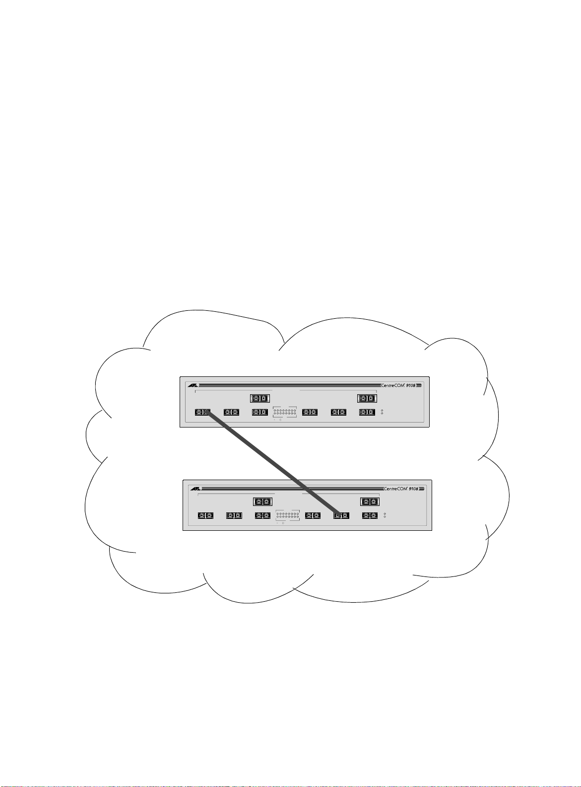
Types of VLANs
Even though they are physically connected to the same switch, for
the members of the different VLANs to communicate, the traffic
must go through the IP routing functionality provided in the switch.
This means that each VLAN must be configured as a router interface
with a unique IP address.
Spanning Switches with Port-Based VLANs.
To create a port-based
VLAN that spans two switches, you must do two things:
❑
Assign the port on each switch to the VLAN.
❑
Cable the two switches together using one port on each
switch per VLAN.
Figure 4-2 illustrates a single VLAN that spans two AT-9108 switches.
All ports on both switches belong to VLAN
Sales
. The two switches
are connected using slot 8, port 4 on System 1, and slot 1, port 1 on
System 2.
Sales
1000BASE-X NETWORK PORTS
1 8
234 567
ACTIVITY
12345678
12345678
LINK
LINK DISABLED
GIGABIT ETHERNET SWITCH
POWER
DIAG
Switch 1
1000BASE-X NETWORK PORTS
1 8
234 567
ACTIVITY
12345678
12345678
LINK
LINK DISABLED
Switch 2
Figure 4-2
Single Port-Based VLAN Spanning Two Switches
GIGABIT ETHERNET SWITCH
POWER
DIAG
4-4
Page 71
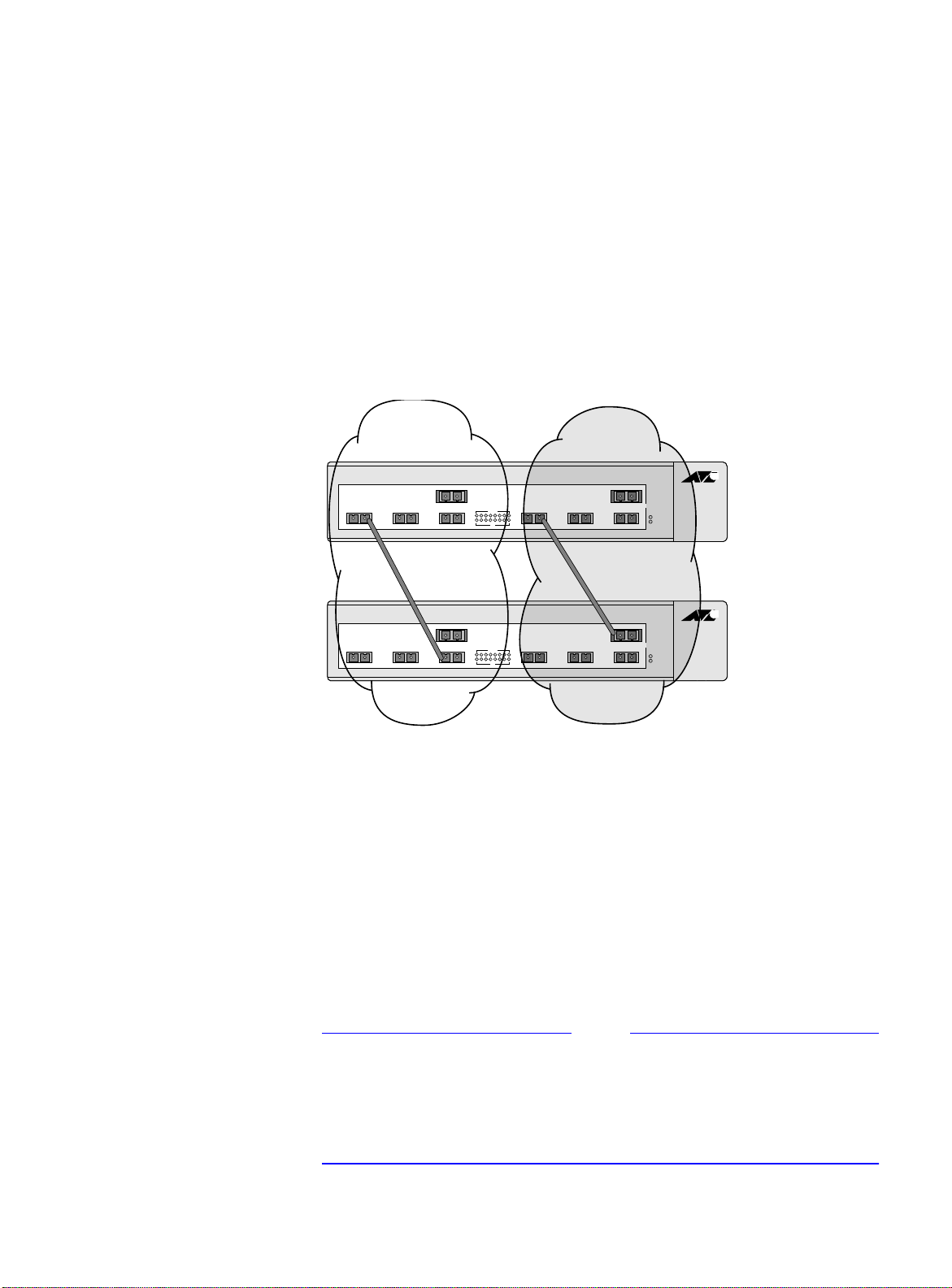
AT-9108, AT-8518, AT-8525, and AT-8550 User’s Guide
Note
Accounting Engineering
1
4
32
1
4
32
8
7
65
8
7
65
Switch 1
Switch 2
To create multiple VLANs that span two switches in a port-based
VLAN, a port on Switch 1 must be cabled to a port on Switch 2 for
each VLAN you want to have span across the switches. At least one
port on each switch must be a member of the corresponding VLANs,
as well.
Figure 4-3 illustrates two VLANs spanning two switches. On Switch 1,
ports 1-4 are part of VLAN
Engineering
. On Switch 2, ports 1-4 are part of VLAN
5 - 8 are part of VLAN
Accounting
Engineering
; ports 5 - 8 are part of VLAN
Accounting
. VLAN
Accounting
spans Switch 1
; ports
and Switch 2 by way of a connection between Switch 1 port 2 and
Switch 2 port 4. VLAN
Engineering
spans Switch 1 and Switch 2 by
way of a connection between Switch 1 port 5 and Switch 2 port 8
Using is configuration, you can create multiple VLANs that span
multiple switches, in a daisy-chained fashion. Each switch must have
a dedicated port for each VLAN. Each dedicated port must be
connected to a port that is a member of its VLAN on the next switch.
Tagged VLANs
Tagging
Ethernet frame. The tag contains the identification number of a
specific VLAN, called the
The use of 802.1Q tagged packets may lead to the appearance of
packets slightly bigger than the current IEEE 802.3/Ethernet
maximum of 1,518 bytes. This may affect packet error counters in
other devices, and may also lead to connectivity problems if non-
802.1Q bridges or routers are placed in the path.
Figure 4-3
Two Port-Based VLANs Spanning Two Switches
is a process that inserts a marker (called a
VLANid
.
tag
) into the
4-5
Page 72

Types of VLANs
Uses of Tagged VLANs.
Tagging is most commonly used to create
VLANs that span switches. The switch-to-switch connections are
typically called
trunks
. Using tags, multiple VLANs can span multiple
switches using one or more trunks. In a port-based VLAN, each VLAN
requires its own pair of trunk ports, as shown in Figure 4-3. Using
tags, multiple VLANs can span two switches with a single trunk.
Another benefit of tagged VLANs is the ability to have a port be a
member of multiple VLANs. This is particularly useful if you have a
device (such as a server) that must belong to multiple VLANs. The
device must have a NIC that supports 802.1Q tagging.
A single port can be a member of only one port-based VLAN. All
additional VLAN membership for the port must be accompanied by
tags. In addition to configuring the VLAN tag for the port, the server
must have a
Network Interface Card (NIC)
that supports 802.1Q
tagging.
Assigning a VLAN Tag.
Each VLAN may be assigned an 802.1Q
VLAN tag. As ports are added to a VLAN with an 802.1Q tag defined,
you decide whether each port will use tagging for that VLAN. The
default mode of the switch is to have all ports assigned to the VLAN
named
default
with an 802.1Q VLAN tag (VLANid) of 1 assigned.
Not all ports in the VLAN must be tagged. As traffic from a port is
forwarded out of the switch, the switch determines (in real time) if
each destination port should use tagged or untagged packet formats
for that VLAN. The switch adds and strips tags, as required, by the
port configuration for that VLAN.
Note
Packets arriving tagged with a VLANid that is not configured in the
switch will be discarded.
Figure 4-4 illustrates the physical view of a network that uses tagged
and untagged traffic.
4-6
Page 73

AT-9108, AT-8518, AT-8525, and AT-8550 User’s Guide
Centre
M S
COM
802.1Q
Tagged server
Switch 1
M S
MM
M
M
S
M S
M
S
S
S
Switch 2
Figure 4-4
Physical Diagram of Tagged and Untagged Traffic
Figure 4-5 shows a logical diagram of the same network.
Marketing
Switch 1
Port 2
Port 4
Switch 2
Port 1
Port 4
Switch 1
Port 1 *
Port 7 *
Switch 2
Port 2 *
Sales
Switch 1
Port 1
Port 6
= Marketing
= Sales
= Tagged port
Centre
COM
Switch 2
Port 7
Port 8
Figure 4-5
Logical Diagram of Tagged and Untagged Traffic
In Figure 4-4 and Figure 4-5:
❑
The trunk port on each switch carries traffic for both VLAN
Marketing
❑
The trunk port on each switch is tagged.
❑
The server connected to slot 1, port 1 on System 1 has a NIC
and VLAN
that supports 802.1Q tagging.
❑
The server connected to slot 1, port 1 on System 1 is a member
of both VLAN
❑
All other stations use untagged traffic.
Marketing
Sales
.
and VLAN
Sales
*Tagged Ports
.
4-7
Page 74

Types of VLANs
As data passes out of the switch, the switch determines if the
destination port requires the frames to be tagged or untagged. All
traffic coming from and going to the server is tagged. Traffic coming
from and going to the trunk ports is tagged. The traffic that comes
from and goes to the other stations on this network is not tagged.
Generic VLAN
Registration
Protocol
Mixing Port-based and Tagged VLANs.
You can configure the
switch using a combination of port-based and tagged VLANs. A
given port can be a member of multiple VLANs, with the stipulation
that only one of its VLANs uses untagged traffic. In other words, a
port can simultaneously be a member of one port-based VLAN and
multiple tag-based VLANs.
Note
For the purposes of VLAN classification, packets arriving on a port
with an 802.1Q tag containing a VLANid of zero are treated as
untagged.
The Generic VLAN Registration Protocol (GVRP) allows a LAN device
to signal other neighboring devices that it wishes to receive packets
for one or more VLANs. The GVRP protocol is defined as part of the
IEEE 802.1Q Virtual LANs draft standard. The main purpose of the
protocol is to allow switches to automatically discover some of the
VLAN information that would otherwise have to be manually
configured in each switch. GVRP can also be run by network servers.
These servers are usually configured to join several VLANs, and then
signal the network switches of the VLANs of which they want to be
part.
4-8
Figure 4-6 illustrates a network using GVRP.
VLAN Red,
Untagged
VLAN Red,
Untagged
Switch A VLAN Red, Tag 10
1000BASE-X
ACTIVITY
LINK ON
DISABLED
56
4
23
1
12
1011
789
1617 18
1415
13
25R
25
A
24
2223
21
1920
25R
25
L
25R
25
POWER
MGMT.
10/100BASE-T ETHERNET SWITCH
WITH GIGABIT ETHERNET
10/100BASE-TX MDI-X
GVRP: "Send
me traffic for
VLAN tag 10."
GVRP: "Send
me traffic for
VLAN tag 10."
Figure 4-6
Network Example Using GVRP
GVRP: "Send
VLAN tag 10."
Switch B
me traffic for
Page 75

AT-9108, AT-8518, AT-8525, and AT-8550 User’s Guide
Note
In Figure 4-6, Switch A is a member of VLAN
Red
. VLAN
Red
has the
VLANid 10. Port 1 and port 2 on Switch A are added to the VLAN as
untagged.
The configuration for Switch A is as follows:
create vlan red
config vlan red tag 10
config vlan red add port 1-2 untagged
enable gvrp
Switch B does not need to be configured with VLAN or tagging
information. Instead, using GVRP, the server connected to Switch B,
and the remainder of the network connected to Switch B provides
Switch B with the information it needs to forward traffic. Switch A
automatically adds port 3 to VLAN
that there are other devices on port 3 that need access to VLAN
Red
because Switch A now knows
Red
VLANs that are automatically created using GVRP with the VLANid 10
are given names in the format
gvrp vlan xxxx
.
where
xxxx
is the VLANid (in decimal) that is discovered by GVRP.
These VLANs are not permanently stored in nonvolatile storage, and
you cannot add or remove ports from these VLANs.
GVRP assumes that the VLANs for which it carries information
operate using VLAN tags, unless explicitly configured otherwise.
Typically, you must configure any untagged VLANs on the switches
at the edges of the network, and the GVRP protocol is used across
the core of the network to automatically configure other switches
using tagged VLANs.
You cannot assign an IP address to a VLAN learned by way of GVRP.
GVRP and Spanning Tree Domains.
Because GVRP-learned VLANs
are dynamic, all VLANs created by GVRP use the system defaults and
become members of the default Spanning Tree Domain (STPD), s0.
Because two STPDs cannot exist on the same physical port, if two
GVRP clients attempt to join two different VLANs that belong to two
different STPDs, the second client is refused. You should configure all
potential GVRP VLANs to be members of the same STPD. This
configuration is done automatically, if you have not configured
additional STPDs.
4-9
Page 76

Types of VLANs
GVRP Commands.
Table 4-1
Table 4-1 describes GVRP commands.
GVRP Commands
Command Description
enable gvrp Enables the Generic VLAN Registration Protocol (GVRP).
The default setting is disabled.
config gvrp {listen | send | both |
none} {port <portlist>}
Configures the sending and receiving GVRP information
one or all a ports. Options include the following:
❑
❑
❑
❑
listen
send
both
none
— Receive GVRP packets.
— Send GVRP packets.
— Send and receive GVRP packets.
— Disable the port from participating in GVRP
operation.
The default setting is
both
.
disable gvrp Disables the Generic VLAN Registration Protocol
(GVRP).
show gvrp Displays the current configuration and status of GVRP.
Protocol-Based
VLANs
Protocol-based VLANs enable you to define a packet filter that the
switch uses as the matching criteria to determine if a particular
packet belongs to a particular VLAN.
Protocol-based VLANs are most often used in situations where
network segments contain hosts running multiple protocols. For
example, in Figure 4-7, the hosts are running both the IP and
NetBIOS protocols.
The IP traffic has been divided into two IP subnets, 192.207.35.0 and
192.207.36.0. The subnets are internally routed by the switch. The
subnets are assigned different VLAN names,
Finance
and
Personnel
,
respectively. The remainder of the traffic belongs to the VLAN named
MyCompany
. All ports are members of the VLAN
MyCompany
.
4-10
Page 77

AT-9108, AT-8518, AT-8525, and AT-8550 User’s Guide
192.207.36.1192.207.35.1
My Company
Finance Personnel
1
Predefined Protocol Filters.
234
Figure 4-7
Protocol-Based VLANs
The following protocol filters are
192.207.36.0192.207.35.0
predefined on the switch:
❑
IP
❑
IPX
❑
NetBIOS
= IP traffic
= All other traffic
❑
DECNet
❑
IPX_8022
❑
IPX_SNAP
❑
AppleTalk
Defining Protocol Filters.
If necessary, you can define a customized
protocol filter based on EtherType, Logical Link Control (LLC), and/or
Subnetwork Access Protocol (SNAP). Up to six protocols may be part
of a protocol filter.
4-11
Page 78

Types of VLANs
To define a protocol filter, do the following:
1. Create a protocol using the following command:
create protocol <protocol_name>
For example:
create protocol fred
The protocol name can have a maximum of 31 characters.
2. Configure the protocol using the following command:
config protocol <protocol_name> add
<protocol_type> <hex_value>
Supported protocol types include:
❑
etype
— EtherType
The values for
etype
are four-digit hexadecimal numbers
taken from a list maintained by the IEEE. This list can be
found at the following URL:
http://standards.ieee.org/regauth/ethert
ype/index.html
❑
llc
— LLC Service Advertising Protocol (SAP)
The values for
llc
are four-digit hexadecimal numbers
that are created by concatenating a two-digit LLC
Destination SAP (DSAP) and a two-digit LLC Source SAP
(SSAP).
❑
snap
— Ethertype inside an IEEE SNAP packet encapsulation.
The values for
snap
are the same as the values for
described previously.
For example:
config protocol fred add llc feff
etype
,
4-12
config protocol fred add snap 9999
A maximum of fifteen protocol filters, each containing a maximum of
six protocols, can be defined. However, no more than seven
protocols can be active and configured for use.
Page 79

AT-9108, AT-8518, AT-8525, and AT-8550 User’s Guide
Note
For more information on SNAP for Ethernet protocol types, see
TR 11802-5:1997 (ISO/IEC) [ANSI/IEEE std. 802.1H, 1997 Edition].
Precedence of
Tagged Packets
Over Protocol
Filters
Deleting a Protocol Filter.
the VLAN is assigned a protocol filter of
If a protocol filter is deleted from a VLAN,
. You can continue to
none
configure the VLAN. However, no traffic is forwarded to the VLAN
until a protocol is assigned to it.
If a VLAN is configured to accept tagged packets on a particular port,
incoming packets that match the tag configuration take precedence
over any protocol filters associated with the VLAN.
4-13
Page 80

VLAN Names
VLAN Names
The switch supports up to 256 different VLANs. Each VLAN is given a
name that can be up to 32 characters. VLAN names can use standard
alphanumeric characters. The following characters are not permitted
in a VLAN name:
❑
Space
❑
Comma
❑
Quotation mark
VLAN names must begin with an alphabetical letter. Quotation
marks can be used to enclose a VLAN name that does not begin with
an alphabetical character, or that contains a space, comma, or other
special character.
VLAN names are locally significant. That is, VLAN names used on one
switch are only meaningful to that switch. If another switch is
connected to it, the VLAN names have no significance to the other
switch.
Default VLAN
Note
You should use VLAN names consistently across your entire network.
The switch ships with one default VLAN that has the following
properties:
❑
The VLAN name is
❑
It contains all the ports on a new or initialized switch.
❑
The default VLAN is untagged on all ports. It has an internal
default.
VLANid of 1.
4-14
Page 81

Configuring VL ANs on the Switch
Note
This section describes the commands associated with setting up
VLANs on the switch.
To configuring a VLAN:
1. Create and name the VLAN.
2. Assign an IP address and mask (if applicable) to the VLAN, if
needed.
Each IP address and mask assigned to a VLAN must represent a
unique IP subnet. You cannot configure the same IP subnet on
different VLANs.
3. Assign a VLANid, if any ports in this VLAN will use a tag.
AT-9108, AT-8518, AT-8525, and AT-8550 User’s Guide
4. Assign one or more ports to the VLAN.
As you add each port to the VLAN, decide if the port will use an
802.1Q tag.
Table 4-2 describes the commands used to configure a VLAN.
Table 4-2
VLAN Configuration Commands
Command Description
create vlan <name> Creates a named VLAN.
create protocol <protocol_name> Creates a user-defined protocol.
enable ignore-stp vlan <name> Enables a VLAN from using STP port information. When
enabled, all virtual ports associated with the VLAN are
in STP forwarding mode. The default setting is
disabled.
config dot1p ethertype <ethertype> Configures an IEEE 802.1Q Ethertype. Use this
command only if you have another switch that
supports 802.1Q, but uses a different Ethertype value
than 8100.
4-15
Page 82

Configuring VLANs on the Switch
Table 4-2
VLAN Configuration Commands
Command Description
config protocol <protocol_name>
[add | delete] <protocol_type>
<hex_value> {<protocol_type>
<hex_value>} ...
Configures a protocol filter. Supported
<protocol_type>
❑
etype
❑
llc
❑
snap
The variable
between 0 and FFFF that represents either the
Ethernet protocol type (for EtherType), the DSAP/SSAP
combination (for LLC), or the SNAP-encoded Ethernet
protocol type (for SNAP).
config vlan <name> ipaddress
<ipaddress> {<mask>}
config vlan <name> add port
<portlist> {tagged | untagged}
Assigns an IP address and an optional mask to the
VLAN.
Adds one or more ports to a VLAN. You can specify
tagged port(s), untagged port(s). By default, ports are
untagged.
config vlan <name> delete port
Deletes one or more ports from a VLAN.
<portlist> {tagged | untagged}
(Continued)
values include:
<hex_value>
is a hexadecimal number
config vlan <name> protocol
[<protocol_name> | any]
Configures a protocol-based VLAN. If the keyword
is specified, then it becomes the default VLAN. All
any
packets that cannot be classified into other protocolbased VLANs are assigned to the default VLAN of that
port.
config vlan <name> qosprofile
<qosname>
Configures a VLAN to use a particular QoS profile.
Dynamic FDB entries associated with the VLAN are
flushed once the change is committed.
config vlan <name> tag <vlanid> Assigns a numerical VLANid. The valid range is from 1
to 4095.
4-16
Page 83

AT-9108, AT-8518, AT-8525, and AT-8550 User’s Guide
VLAN
Configuration
Examples
The following example creates a tag-based VLAN named
video
. It
assigns the VLANid 1000. Ports 4 through 8 are added as tagged
ports to the VLAN.
create vlan video
config video tag 1000
config video add port 4-8 tagged
The following example creates a VLAN named
sales
, with the VLANid
120. The VLAN uses both tagged and untagged ports. Ports 1
through 3 are tagged, and ports 4 and 7 are untagged. Note that
when not explicitly specified, ports are added as untagged.
create vlan sales
config sales tag 120
config sales add port 1-3 tagged
config sales add port 4,7
4-17
Page 84

Displaying VLAN Settings
Displaying VLAN Settings
To display VLAN settings, use the following command:
show vlan {<name> | all}
The
command displays summary information about each
show
VLAN, and includes the following:
❑
Name
❑
VLANid
❑
How the VLAN was created (manually or by GVRP)
❑
IP address
❑
STPD information
❑
Protocol information
❑
QoS profile information
❑
Ports assigned
❑
Tagged/untagged status for each port
❑
How the ports were added to the VLAN (manually or by GVRP)
To display protocol information, use the following command:
show protocol {<protocol> | all}
show
This
command displays protocol information, including the
following:
❑
Protocol name
❑
List of protocol fields
❑
VLANs that use the protocol
4-18
Page 85

Deleting VLANs
AT-9108, AT-8518, AT-8525, and AT-8550 User’s Guide
To delete a VLAN, or to return VLAN settings to their defaults, use the
commands listed in Table 4-3.
Table 4-3
VLAN Delete and Reset Commands
Command Description
disable ignore-stp vlan <name> Allows a VLAN to use STP port information.
unconfig vlan <name> ipaddress Resets the IP address of the VLAN.
delete vlan <name> Removes a VLAN.
delete protocol <protocol> Removes a protocol.
4-19
Page 86

Page 87

Chapter 5
Forwarding Database (FDB)
This chapter describes the contents of the forwarding database
(FDB), how the FDB works, and how to configure the FDB.
Overview of the FDB
The switch maintains a database of all media access control (MAC)
addresses received on all of its ports. It uses the information in this
database to decide whether a frame should be forwarded or filtered.
FDB Contents
FDB Entry Types
The database holds up to a maximum of 128K entries. Each entry
consists of the MAC address of the device, an identifier for the port
on which it was received, and an identifier for the VLAN to which the
device belongs. Frames destined for devices that are not in the FDB
are flooded to all members of the VLAN.
The following are three types of entries in the FDB:
❑
Dynamic entries
dynamic. Entries in the database are removed (aged-out) if,
after a period of time (aging time), the device has not
transmitted. This prevents the database from becoming full
with obsolete entries by ensuring that when a device is
removed from the network, its entry is deleted from the
database. Dynamic entries are deleted from the database if
the switch is reset or a power off/on cycle occurs. For more
information about setting the aging time, refer to the section
“Configuring FDB Entries,” later in this chapter.
— Initially, all entries in the database are
5-1
Page 88

Overview of the FDB
❑
Non-aging entries
— If the aging time is set to zero, all aging
entries in the database are defined as static, non-aging entries.
This means that they do not age, but they are still deleted if
the switch is reset.
❑
Permanent entries
— Permanent entries are retained in the
database if the switch is reset or a power off/on cycle occurs.
The system administrator must make entries permanent. A
permanent entry can either be a unicast or multicast MAC
address. All entries entered by way of the command-line
interface are stored as permanent. The switch can support a
maximum of 64 permanent entries.
Once created, permanent entries stay the same as when they were
created. For example. the permanent entry store is not updated
when any of the following take place:
— A VLAN is deleted.
— A VLANid is changed.
— A port mode is changed (tagged/untagged).
— A port is deleted from a VLAN.
How FDB Entri es
Get Added
— A port is disabled.
— A port enters blocking state.
— A port QoS setting is changed.
— A port goes down (link down).
❑
Blackhole entrie
s — A blackhole entry configures packets
with a specified MAC destination address to be discarded.
Blackhole entries are useful as a security measure or in special
circumstances where a specific destination address must be
discarded. Blackhole entries are treated like permanent
entries in the event of a switch reset or power off/on cycle.
Blackhole entries are never aged out of the database.
Entries are added into the FDB in the following two ways:
❑
The switch can learn entries. The system updates its FDB with
the source MAC address from a packet, the VLAN, and the port
identifier on which the source packet is received.
❑
You can enter and update entries using a MIB browser, an
SNMP Network Manager, or the command-line interface (CLI).
5-2
Page 89

AT-9108, AT-8518, AT-8525, and AT-8550 User’s Guide
Note
Associating a QoS
Profile with an
FDB Entry
You can associate a QoS profile with a MAC address (and VLAN) of a
device that will be dynamically learned. The FDB treats the entry like
a dynamic entry (it is learned, it can be aged out of the database, and
so on). The switch applies the QoS profile as soon as the FDB entry is
learned.
For more information on QoS, refer to Chapter 7.
5-3
Page 90

Configuring FDB Entries
Configuring FDB Entries
To configure entries in the FDB, use the commands listed in
Table 5-1.
Table 5-1
FDB Configuration Commands
Command Description
create fdbentry <mac_address> vlan
<name> [blackhole | <portlist> |
dynamic] {qosprofile <qosname>}
Creates an FDB entry. Specify the following:
mac_address
❑
— Device MAC address, using
colon separated bytes.
name
❑
❑
blackhole
VLAN associated with MAC address.
—
Configures the MAC address as a
—
blackhole entry.
portlist
❑
Port numbers associated with
—
MAC address.
dynamic
❑
pecifies that the entry will be
— S
learned dynamically. Used to associated a QoS
profile with a dynamically learned entry.
qosname
❑
QoS profile associated with MAC
—
address.
If more than one port number is associated with a
permanent MAC entry, packets are multicast to the
multiple destinations.
config fdb agingtime <number> Configures the FDB aging time. The range is 15
through 1,000,000 seconds. The default value is 300
seconds. A value of 0 indicates that the entry should
never be aged out.
enable learning port <portlist> Enables MAC address learning on one or more
ports.
disable learning port <portlist> Disables MAC address learning on one or more
ports for security purposes. If MAC address learning
is disabled, only broadcast traffic, EDP traffic, and
packets destined to a permanent MAC address
matching that port number, are forwarded. The
default setting is enabled.
5-4
Page 91

AT-9108, AT-8518, AT-8525, and AT-8550 User’s Guide
FDB
Configuration
Examples
The following example adds a permanent entry to the FDB:
create fdbentry 00:E0:2B:12:34:56 vlan
marketing port 4
The permanent entry has the following characteristics:
❑
MAC address is 00E02B123456.
❑
VLAN name is
❑
Slot number for this device is 3.
❑
Port number for this device is 4.
marketing
.
This example associates the QoS profile qp2 with a dynamic entry
that will be learned by the FDB:
create fdbentry 00:A0:23:12:34:56 vlan net34
dynamic qosprofile qp2
This entry has the following characteristics:
❑
MAC address is 00A023123456.
❑
VLAN name is
❑
The entry will be learned dynamically.
❑
QoS profile
net34
.
qp2
will be applied when the entry is learned.
5-5
Page 92

Displaying FDB Entries
Displaying FDB Entries
To display FDB entries, use the command
show fdb {<mac_address> | vlan <name> |
<portlist> | permanent | qos}
where the following is true:
❑
mac_address
address.
❑
vlan <name>
❑
portlist
combination.
❑
permanent
❑
qos
— Displays all entries that are associated with a QoS
profile.
— Displays the entry for a particular MAC
— Displays the entries for a VLAN.
— Displays the entries for a slot and port
— Displays all permanent entries.
With no options, the command displays all FDB entries.
5-6
Page 93

Removing FDB Entries
You can remove one or more specific entries from the FDB, or you
can clear the entire FDB of all entries by using the commands listed
in Table 5-2.
AT-9108, AT-8518, AT-8525, and AT-8550 User’s Guide
Table 5-2
Removing FDB Entry Commands
Command Description
delete fdbentry <mac_address> vlan
Deletes a permanent FDB entry.
<name>
clear fdb {<mac_address> | vlan
<name> | <portlist>}
Clears dynamic FDB entries that match the filter.
When no options are specified, the command clears
all FDB entries.
5-7
Page 94

Page 95

Chapter 6
Note
Spanning Tree Protocol (STP)
Using the Spanning Tree Protocol (STP) functionality of the switch
makes your network more fault tolerant. The following sections
explain more about STP and the STP features supported by the
switch software.
STP is a part of the 802.1D bridge specification defined by the IEEE
Computer Society. To explain STP in terms used by the 802.1D
specification, the Gigabit switch will be referred to as a bridge.
Overview of the Spanning Tree Protocol
STP is a bridge-based mechanism for providing fault tolerance on
networks. STP allows you to implement parallel paths for network
traffic, and ensure that
❑
Redundant paths are disabled when the main paths are
operational.
❑
Redundant paths are enabled if the main path fails.
6-1
Page 96

Spanning Tree Protocol Domains
Spanning Tree Prot oc ol Doma in s
The switch can be partitioned into multiple virtual bridges. Each
virtual bridge can run an independent Spanning Tree instance. Each
Spanning Tree instance is called a
Each STPD has its own Root Bridge and active path. Once the STPD is
created, one or more VLANs can be assigned to it.
A port can belong to only one STPD. If a port is a member of multiple
VLANs, then all those VLANs must belong to the same STPD.
The key points to remember when configuring VLANs and STP are
the following:
❑
Each VLAN forms an independent broadcast domain.
❑
STP blocks paths to create a loop-free environment.
❑
When STP blocks a path, no data can be transmitted or
received on the blocked port.
Spanning Tree Domain
(STPD).
❑
Within any given STPD, all VLANs belonging to it use the same
spanning tree.
Caution
Care must be taken to ensure that multiple STPD instances within a
single switch do not see each other in the same broadcast domain.
This could happen if, for example, another external bridge is used to
connect VLANs belonging to separate STPDs.
If you delete an STPD, the VLANs that were members of that STPD are
also deleted. You must remove all VLANs associated with the STP
before deleting the STPD.
Caution
If no VLANs are configured to use the protocol filter
any
on a
particular port, STP BPDUs are not flooded within a VLAN when STP is
turned off. If you need STP to operate on this type of port, enable STP
on the associated VLAN, so that it can participate.
6-2
Page 97

AT-9108, AT-8518, AT-8525, and AT-8550 User’s Guide
Note
STPD Status for
GVRP-Added
Ports
Defaults
If a port is added to a VLAN by GVRP, the newly added port reflects
the SPTD membership and status of the VLAN to which it is added.
For example, if VLAN
then all ports added to VLAN
ports, as well. The command for disabling STP on a port basis
permanent affect on ports controlled by GVRP.
For more information on GVRP, refer to Chapter 4.
The default device configuration contains a single STPD called s0.
The default VLAN is a member of STPD s0.
All STP parameters default to the IEEE 802.1D values, as appropriate.
Red
is a member of STPD s0, and s0 is enabled,
Red
by GVRP have s0 enabled on those
has
no
6-3
Page 98
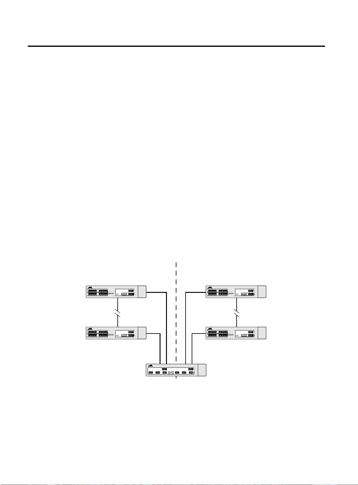
STP Configurations
STP Configuratio ns
When you assign VLANs to an STPD, pay careful attention to the STP
configuration and its effect on the forwarding of VLAN traffic.
Figure 6-1 illustrates a network that uses VLAN tagging for trunk
connections. The following four VLANs have been defined:
❑
Sales
is defined on Switch A, Switch B, and Switch M.
❑
Personnel
❑
Manufacturing
❑
Engineering
❑
Marketing
is defined on Switch A, Switch B, and Switch M.
is defined on Switch Y, Switch Z, and Switch M.
is defined on Switch Y, Switch Z, and Switch M.
is defined on all switches (Switch A, Switch B, Switch
Y, Switch Z, and Switch M).
Two STPDs are defined:
❑
STPD1 contains VLANs
❑
STPD2 contains VLANs
The VLAN
Marketing
is a member of the default STPD, bu t not
Sales
and
Personnel.
Manufacturing
Engineering.
and
assigned to either STPD1 or STPD2.
Sales, Personnel, Marketing
Centre
COM
Switch A Switch Y
Centre
COM
Switch B
STPD 1 STPD 2
Manufacturing, Engineering, Marketing
Centre
COM
Centre
COM
Switch Z
Switch M
Centre
COM
6-4
Sales, Personnel, Manufacturing, Engineering, Marketing
Figure 6-1
Multiple Spanning Tree Domains
Page 99

AT-9108, AT-8518, AT-8525, and AT-8550 User’s Guide
When the switches in this configuration start up, STP configures each
STPD such that there are no active loops in the topology. STP could
configure the topology in a number of ways to make it loop-free.
In Figure 6-1, the connection between Switch A and Switch B is put
into blocking state, and the connection between Switch Y and
Switch Z is put into blocking state. After STP converges, all the VLANs
can communicate, and all bridging loops are prevented.
The VLAN
Marketing
, which has not been assigned to either STPD1 or
STPD2, communicates using all five switches. The topology has no
loops, because STP has already blocked the port connection
between Switch A and Switch B, and between Switch Y and Switch Z.
Within a single STPD, you must be extra careful when configuring
your VLANs. Figure 6-2 illustrates a network that has been incorrectly
set up using a single STPD so that the STP configuration disables the
ability of the switches to forward VLAN traffic.
Marketing & Sales Marketing, Sales & Engineering
Centre
COM
Switch 1 Switch 3
Centre
COM
Centre
COM
Switch 2
Sales & Engineering
Figure 6-2
Tag-Based STP Configuration
The tag-based network in Figure 6-2 has the following configuration:
❑
Switch 1 contains VLAN
❑
Switch 2 contains VLAN
❑
Switch 3 contains VLAN
VLAN
❑
The tagged trunk connections for three switches form a
Sales
.
Marketing
and VLAN
Engineering
Marketing
, VLAN
and VLAN
Engineering
Sales
Sales
.
.
, and
triangular loop that is not permitted in an STP topology.
❑
All VLANs in each switch are members of the same STPD.
6-5
Page 100

STP Configurations
STP may block traffic between Switch 1 and Switch 3 by disabling the
trunk ports for that connection on each switch.
Switch 2 has no ports assigned to VLAN marketing. Therefore, if the
trunk for VLAN marketing on Switches 1 and 3 is blocked, the traffic
for VLAN marketing will not be able to traverse the switches.
6-6
 Loading...