


Allegro A3189LUA, A3189LU, A3189LLT, A3189EUA, A3189EU Datasheet
...3185 THRU
3189
Sheet Data 2A.27609
HALL-EFFECT LATCHES FOR HIGH-TEMPERATURE OPERATION
X
VCC
|
|
|
|
|
|
|
|
1 |
|
2 |
|
3 |
|
|
|
|
|
|
|
|
SUPPLY |
GROUND |
OUTPUT |
|
|
Dwg. PH-003A |
Pinning is shown viewed from branded side.
ABSOLUTE MAXIMUM RATINGS
at TA = +25°C
Supply Voltage, VCC ............................ |
30 V |
|
Reverse Battery Voltage, VRCC ........... |
-30 |
V |
Magnetic Flux Density, B ........... |
Unlimited |
|
Output OFF Voltage, VOUT .................. |
30 V |
|
Reverse Output Voltage, VOUT .......... |
-0.5 |
V |
Continuous Output Current, IOUT ..... 25 mA
Operating Temperature Range, TA
Suffix ‘E–’ |
................... -40°C to +85°C |
Suffix ‘L–’ ................. |
-40°C to +150°C |
Storage Temperature Range, |
|
TS ............................... |
-65°C to +170°C |
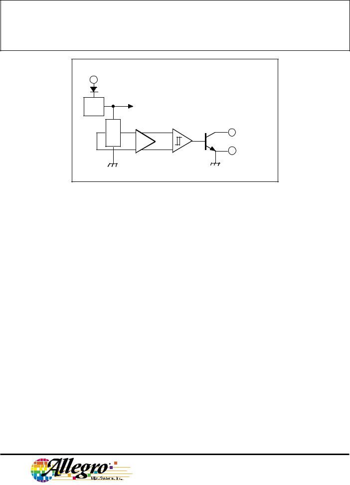
These Hall-effect latches are extremely temperature-stable and stressresistant sensors especially suited for operation over extended temperature ranges to +150°C. Superior high-temperature performance is made possible through a novel Schmitt trigger circuit that maintains operate and release point symmetry by compensating for temperature changes in the Hall element. Additionally, internal compensation provides magnetic switch points that become more sensitive with temperature, hence offsetting the usual degradation of the magnetic field with temperature. The symmetry capability makes these devices ideal for use in pulse-counting applications where duty cycle is an important parameter. The four basic devices (3185, 3187, 3188, and 3189) are identical except for magnetic switch points.
Each device includes on a single silicon chip a voltage regulator, quadratic Hall-voltage generator, temperature compensation circuit, signal amplifier, Schmitt trigger, and a buffered open-collector output to sink up to 25 mA. The on-board regulator permits operation with supply voltages of 3.8 to 24 volts.
The first character of the part number suffix determines the device operating temperature range. Suffix ‘E–’ is for -40°C to +85°C, and suffix ‘L–’ is for -40°C to +150°C. Three package styles provide a magnetically optimized package for most applications. Suffix ‘–LT’ is a miniature SOT- 89/TO-243AA transistor package for surface-mount applications; suffix ‘–U’ is a three-lead plastic mini-SIP, while suffix ‘–UA’ is a three-lead ultra-mini- SIP.
FEATURES
■Symmetrical Switch Points
■Superior Temperature Stability
■Operation From Unregulated Supply
■Open-Collector 25 mA Output
■Reverse Battery Protection
■Activate With Small, Commercially Available Permanent Magnets
■Solid-State Reliability
■Small Size
■Resistant to Physical Stress
Always order by complete part number: the prefix ‘A’ + the basic four-digit part number + a suffix to indicate operating temperature range +
a suffix to indicate package style, e.g., A3185ELT .
3185 THRU 3189
HALL-EFFECT LATCHES FOR HIGH-TEMPERATURE OPERATION
FUNCTIONAL BLOCK DIAGRAM
1 VCC
REG.
X |
3 OUTPUT
2 GROUND
Dwg. FH-005-3
ELECTRICAL CHARACTERISTICS over operating temperature range, at VCC = 12 V.
|
|
|
|
Limits |
|
|
|
|
|
|
|
|
|
Characteristic |
Symbol |
Test Conditions |
Min. |
Typ. |
Max. |
Units |
|
|
|
|
|
|
|
Supply Voltage |
VCC |
Operating |
3.8 |
— |
24 |
V |
Output Saturation Voltage |
VOUT(SAT) |
IOUT = 20 mA, B > BOP |
— |
175 |
400 |
mV |
Output Leakage Current |
IOFF |
VOUT = 24 V, B < BRP |
— |
0.05 |
5.0 |
µA |
Supply Current |
ICC |
B < BRP (Output OFF) |
— |
4.75 |
8.0 |
mA |
|
|
B > BOP (Output ON) |
— |
5.7 |
— |
mA |
|
|
|
|
|
|
|
Output Rise Time |
tr |
RL = 820 Ω, CL = 20 pF |
— |
100 |
— |
ns |
Output Fall Time |
tf |
RL = 820 Ω, CL = 20 pF |
— |
100 |
— |
ns |
|
|
|
|
|
|
|
MAGNETIC CHARACTERISTICS in gauss over operating supply voltage range.
|
|
|
|
|
|
Part Numbers* |
|
|
|
|
|
|
|
|
|
|
|
|
|||
|
|
|
A3185 |
|
A3187 |
A3188 |
A3189 |
|||
|
|
|
|
|
|
|
|
|
|
|
Characteristic |
Min. |
Max. |
Min. |
Max. |
Min. |
Max. |
Min. |
Max. |
||
|
|
|
|
|
|
|
|
|
|
|
BOP at TA = 25°C |
170 |
270 |
50 |
150 |
100 |
180 |
50 |
230 |
||
|
|
|
|
|
|
|
|
|
|
|
over operating temp. range |
140 |
300 |
50 |
175 |
80 |
200 |
50 |
250 |
||
|
|
|
|
|
|
|
|
|
|
|
BRP at TA = 25°C |
-270 |
-170 |
-150 |
-50 |
-180 |
-100 |
-230 |
-50 |
||
|
|
|
|
|
|
|
|
|
|
|
over operating temp. range |
-300 |
-140 |
-175 |
-50 |
-200 |
-80 |
-250 |
-50 |
||
|
|
|
|
|
|
|
|
|
|
|
Bhys at TA = 25°C |
340 |
540 |
100 |
300 |
200 |
360 |
100 |
460 |
||
|
|
|
|
|
|
|
|
|
|
|
over operating temp. range |
280 |
600 |
100 |
350 |
160 |
400 |
100 |
500 |
||
|
|
|
|
|
|
|
|
|
|
|
NOTES: BOP = operate point (output turns ON); BRP = release point (output turns OFF); Bhys = hysteresis (BOP - BRP). As used here, negative flux densities are defined as less than zero (algebraic convention).
*Complete part number includes a suffix to identify operating temperature range (E or L) and package type ( LT, U, or UA).
115 Northeast Cutoff, Box 15036
Worcester, Massachusetts 01615-0036 (508) 853-5000
Copyright © 1995, 1999, Allegro MicroSystems, Inc.

3185 THRU 3189
HALL-EFFECT LATCHES FOR HIGH-TEMPERATURE OPERATION
TYPICAL OPERATING CHARACTERISTICS
|
|
|
|
A3185* SWITCH POINTS |
|||||||||||
|
300 |
|
|
|
|
|
|
|
|
|
|
|
|
|
|
|
200 |
|
|
|
|
|
|
|
|
|
|
|
|
|
|
GAUSSIN |
|
|
OPERATE POINT |
|
|
|
|
|
|
|
|
|
|
||
|
|
|
|
|
|
|
|
|
|
|
|
||||
100 |
|
|
|
|
|
|
|
|
VCC = |
12 V |
|
|
|||
|
|
|
|
|
|
|
|
|
|
||||||
|
|
|
|
|
|
|
|
|
|
|
|
|
|
|
|
POINT |
0 |
|
|
|
|
|
|
|
|
|
|
|
|
|
|
|
|
|
|
|
|
|
|
|
|
|
|
|
|
||
|
|
|
|
|
|
|
|
|
|
|
|
|
|
||
|
|
|
|
|
|
|
|
|
|
|
|
|
|
|
|
SWITCH |
-100 |
|
|
|
|
|
|
|
|
|
|
|
|
|
|
|
|
|
|
|
|
|
|
|
|
|
|
|
|
|
|
|
|
|
|
|
|
|
|
|
|
|
|
|
|
|
|
|
|
|
|
|
|
|
|
RELEASE POINT |
|
|
|
|
|||
|
-200 |
|
|
|
|
|
|
|
|
|
|
|
|
|
|
|
-300 |
|
|
|
|
|
|
|
|
|
|
|
|
|
|
|
|
|
|
|
|
|
|
|
|
|
|
|
|
|
|
|
-50 |
-25 0 25 50 75 100 125 150 |
|||||||||||||
AMBIENT TEMPERATURE IN °C
Dwg. GH-026
OUTPUT SATURATION VOLTAGE
300
|
|
|
I OUT = 20 mA |
|
|
|
|
|
|
|
|
|
VCC = 4.5–24 V |
|
|
|
|
|
|
IN mV |
200 |
|
|
|
|
|
|
|
|
VOLTAGE |
|
|
|
|
|
|
|
|
|
SATURATION |
100 |
|
|
|
|
|
|
|
|
|
0 |
|
|
|
|
|
|
|
150 |
|
-50 |
-25 |
0 |
25 |
50 |
75 |
100 |
125 |
|
|
|
|
AMBIENT TEMPERATURE IN °C |
|
|
|
|||
|
|
|
|
|
|
|
|
Dwg. GH-029 |
|
SUPPLY CURRENT
10
8.0
IN mA |
|
|
|
|
|
|
|
|
|
|
|
|
|
|
|
B ≥ B OP |
|
|
|
|
|
|
|
CURRENT |
6.0 |
|
|
|
|
|
|
|
|
|
|
|
|
|
|
|
B ≤ BRP |
|
|
||||
|
|
|
|
|
|
|
|
|
|||
SUPPLY |
4.0 |
|
|
|
|
|
|
|
|
|
|
|
|
|
|
|
|
|
|
|
|
|
|
|
|
|
|
|
|
|
|
|
|
|
|
|
2.0 |
|
|
|
|
|
|
TA = +25°C |
|
|
|
|
|
|
|
|
|
|
|
|
|||
|
0 |
|
|
|
|
|
|
|
|
|
|
|
|
|
|
|
|
|
|
|
|
|
|
|
0 |
5 |
10 |
15 |
20 |
25 |
|||||
SUPPLY VOLTAGE IN VOLTS
Dwg. GH-030
|
|
|
|
|
A3187* SWITCH POINTS |
|
|
||||||||||||||||||
|
150 |
|
|
|
|
|
|
|
|
|
|
|
|
|
|
|
|
|
|
|
|
|
|
|
|
|
100 |
|
|
|
|
|
|
|
|
|
|
|
|
|
|
|
|
|
|
|
|
|
|
|
|
|
|
|
OPERATE POINT |
|
|
|
|
|
|
|
|
|
|
|
|
|
|
|
|
||||||
|
|
|
|
|
|
|
|
|
|
|
|
|
|
|
|
|
|
|
|
|
|||||
GAUSSIN |
50 |
|
|
|
|
|
|
|
|
|
|
|
|
|
|
|
VCC = |
12 V |
|
|
|
||||
|
|
|
|
|
|
|
|
|
|
|
|
|
|
|
|
|
|
||||||||
|
|
|
|
|
|
|
|
|
|
|
|
|
|
|
|
|
|
|
|
|
|
|
|
|
|
POINT |
0 |
|
|
|
|
|
|
|
|
|
|
|
|
|
|
|
|
|
|
|
|
|
|
|
|
|
|
|
|
|
|
|
|
|
|
|
|
|
|
|
|
|
|
|
|
|
|
|
|
||
|
|
|
|
|
|
|
|
|
|
|
|
|
|
|
|
|
|
|
|
|
|
|
|||
|
|
|
|
|
|
|
|
|
|
|
|
|
|
|
|
|
|
|
|
|
|
|
|
|
|
SWITCH |
-50 |
|
|
|
|
|
|
|
|
|
|
|
|
RELEASE POINT |
|
|
|
|
|
|
|
||||
|
|
|
|
|
|
|
|
|
|
|
|
|
|
|
|
|
|
|
|
|
|
|
|
|
|
|
-100 |
|
|
|
|
|
|
|
|
|
|
|
|
|
|
|
|
|
|
|
|
|
|
|
|
|
|
|
|
|
|
|
|
|
|
|
|
|
|
|
|
|
|
|
|
|
|
|
|
|
|
|
|
|
|
|
|
|
|
|
|
|
|
|
|
|
|
|
|
|
|
|
|
|
|
|
|
|
|
|
|
|
|
|
|
|
|
|
|
|
|
|
|
|
|
|
|
|
|
|
|
||
|
-150 |
|
|
|
|
|
|
|
|
|
|
|
|
|
|
|
|
|
|
|
|
|
|
|
|
|
-50 |
-25 |
0 |
|
25 |
|
50 |
75 |
100 |
125 |
|
150 |
|||||||||||||
|
|
|
|
|
|
AMBIENT TEMPERATURE IN °C |
|
|
|
Dwg. GH-027 |
|||||||||||||||
|
|
|
|
|
|
|
|
|
|
|
|
|
|
|
|
|
|
|
|
|
|
||||
|
|
|
|
|
|
SUPPLY CURRENT |
|
|
|
|
|
|
|
||||||||||||
|
7.0 |
|
|
|
|
|
|
|
|
|
|
|
|
|
|
|
|
|
|
|
|
|
|
|
|
|
|
|
|
|
|
|
|
|
|
|
|
|
|
|
|
|
|
|
|
|
|
|
|
||
|
|
|
|
|
|
|
|
|
|
|
|
|
|
|
|
|
|
|
|
|
|
|
|
|
|
mA |
6.0 |
|
|
|
|
|
|
|
|
|
|
|
|
|
|
|
|
|
VCC = 12 V |
|
|
||||
|
|
|
|
|
|
|
|
|
|
|
|
|
|
|
|
|
|
|
|||||||
|
|
|
|
|
|
|
|
|
|
|
|
|
|
|
|
|
|
|
|
|
|
|
|||
IN |
|
|
|
|
|
|
|
|
|
|
|
|
|
|
|
|
|
|
|
|
|
|
|
||
|
|
|
|
|
|
|
|
B ≥ B OP |
|
|
|
|
|
|
|
|
|
|
|
|
|
|
|||
CURRENT |
|
|
|
|
|
|
|
|
|
|
|
|
|
|
|
|
|
|
|
|
|
|
|||
|
|
|
|
|
|
|
|
|
|
|
|
|
|
|
|
|
|
|
|
|
|
|
|
|
|
|
|
|
|
|
|
|
|
|
|
|
|
|
|
|
|
|
|
|
|
|
|
|
|
|
|
SUPPLY |
5.0 |
|
|
|
|
|
|
|
|
|
|
|
|
|
|
|
|
|
|
|
|
|
|
|
|
|
|
|
|
|
|
|
|
|
|
|
|
|
|
|
|
|
|
|
|
|
|
|
|
||
|
|
|
|
|
|
|
|
|
|
|
|
|
|
|
|
|
|
|
|
|
|
|
|
|
|
|
|
|
|
|
|
|
|
|
|
|
|
|
|
|
|
|
|
B ≤ BRP |
|
|
|
||||
|
4.0 |
|
|
|
|
|
|
|
|
|
|
|
|
|
|
|
|
|
|
|
|
|
|
|
|
|
-50 |
-25 |
0 |
25 |
|
50 |
75 |
100 |
125 |
|
150 |
||||||||||||||
|
|
|
|
|
|
AMBIENT TEMPERATURE IN °C |
|
|
|
Dwg. GH-028 |
|||||||||||||||
|
|
|
|
|
|
|
|
|
|
|
|
|
|
|
|
|
|
|
|
|
|
||||
|
|
|
|
|
|
|
|
OPERATE POINT |
|
|
|
|
|
|
|
||||||||||
GAUSS |
20 |
|
|
|
|
|
|
|
|
|
|
|
|
|
|
|
|
|
|
|
|
|
|
|
|
15 |
|
|
|
|
|
|
|
|
|
|
|
|
|
|
|
|
|
|
|
|
|
|
|
|
|
|
|
|
|
|
|
|
|
|
|
|
|
|
|
|
|
|
|
|
|
|
|
|
|
|
|
|
|
|
|
|
|
|
|
|
|
|
|
|
|
|
|
|
|
|
|
|
|
|
|||
IN |
|
|
|
|
|
|
|
|
|
|
|
|
|
|
|
|
|
TA = +25°C |
|
|
|
||||
|
|
|
|
|
|
|
|
|
|
|
|
|
|
|
|
|
|
|
|
|
|
|
|
|
|
POINT |
10 |
|
|
|
|
|
|
|
|
|
|
|
|
|
|
|
|
|
|
|
|
|
|
|
|
OPERATEIN |
5.0 |
|
|
|
|
|
|
|
|
|
|
|
|
|
|
|
|
|
|
|
|
|
|
|
|
CHANGE |
|
|
|
|
|
|
|
|
|
|
|
|
|
|
|
|
|
|
|
|
|
|
|
|
|
0 |
|
|
|
|
|
|
|
|
|
|
|
|
|
|
|
|
|
|
|
|
|
|
|
|
|
|
|
|
|
|
|
|
|
|
|
|
|
|
|
|
|
|
|
|
|
|
|
|
|
|
|
|
-5.0 |
|
|
|
|
|
|
|
|
|
|
|
|
|
|
|
|
|
|
|
|
|
|
|
|
|
|
|
|
|
|
|
|
|
|
|
|
|
|
|
|
|
|
|
|
|
|
|
|
|
|
|
|
|
|
|
|
|
|
|
|
|
|
|
|
|
|
|
|
|
|
|
|
|
|
|
|
|
0 |
|
5 |
|
|
10 |
|
|
15 |
|
|
|
20 |
|
|
|
25 |
||||||||
SUPPLY VOLTAGE IN VOLTS
Dwg. GH-037
* Complete part number includes a suffix denoting operating temperature range (E or L) and package type (LT, U, or UA).
 Loading...