

Page 1

Rhein Tech Laboratories Client: Alinco, Inc
360 Herndon Parkway Model: DR-135TMkII
Suite 1400 Standards: FCC 15.121/IC RSS-215
Herndon, VA 20170 Report #: 2002221
http://www.rheintech.com
Date: January 31, 2003
APPENDIX H: MANUAL
Please see the following pages.
Page 23 of 51
Page 2
VHF FM Mobile Transceiver
DR-135T
Instruction Manual
Thank you for purchasing your new Alinco transceiver.
This instruction manual contains important safety and operating instructions. Please read this
manual carefully before using the product and keep it for future reference.
Page 3

NOTICE / Compliance Information Statement
This equipment has been tested and found to comply with the limits for a Class B digital device, pursuant
to part 15 of the FCC Rules.
These limits are designed to provide reasonable protection against harmful interference in a residential
installation. This equipment generates, uses, and can radiate radio frequency energy and, if not installed
and used in accordance with the instruction manual, may cause harmful interference to radio communica-
tions. However, there is no guarantee that interference will not occur in a particular installation. If this
equipment does cause harmful interference to radio or television reception, which can be determined by
turning the equipment off and on, the user is encouraged to try to correct the interference by one or more
of the following measures:
• Reorient or relocate the receiving antenna.
• Increase the separation between the equipment and receiver.
• Connect the equipment into an outlet on a circuit different from that to which the receiver is
connected.
• Consult the dealer or an experienced radio/TV technician for help.
Tested to Comply
With FCC Standards
FOR HOME OR OFFICE USE
Information in this document is subject to change without notice or obligation. All brand names and
trademarks are the property of their respective owners. Alinco cannot be liable for pictorial or typographi-
cal inaccuracies. Some parts, options and/or accessories are unavailable in certain areas. Changes or modi-
fications not expressly approved by the party responsible for compliance could void the user's authority to
operate the equipment.
VHF FM Transceiver DR-135TMK
This device complies with Part 15 of the FCC Rules. Operation is subject to the following two conditions:
(1) This device may not cause harmful interference, and (2) this device must accept any interference
received, including interference that may cause undesired operation.
U.S. Representative:
ATOC Amateur Distributing LLC, 23 South High St. Covington, OH 45318 USA Ph. 937-473-2840
Copyright © 2000 All rights reserved. No part of this document may be reproduced, copied, translated or
transcribed in any form or by any means without the prior written permission of Alinco. Inc., Osaka,
Japan. English Edition Printed in Japan.
Page 4

Contents
Before operating the transceiver ...................................... 3
Introduction ........................................................................ 3
1. New and Innovative Features ........................................ 4
2. Standard Accessories.................................................... 5
3. Initial Installation ............................................................ 6
For a base station set up ....................................................................... 6
For a mobile station set up .................................................................... 7
External power supply control & Power lamp functions ......................... 8
Power supply voltage display function ................................................... 8
4. Part Names and Functions ............................................ 9
Front Panel ............................................................................................ 9
Rear Panel ........................................................................................... 10
Display ................................................................................................. 11
Microphone .......................................................................................... 12
5. Basic Operations .......................................................... 13
Turning the unit on and off ................................................................... 13
Audio Volume level setting .................................................................. 13
Squelch level setting ............................................................................ 13
VFO mode ........................................................................................... 14
[Change frequency by the channel step] ................................ 14
[Change frequency by 1 MHz step] ........................................ 14
Changing the channel step .................................................................. 15
REPEATER (DUPLEX) Operation ....................................................... 15
CTCSS / DCS setting .......................................................................... 16
Memory Mode ...................................................................................... 17
[Memory programming] ........................................................... 17
[Programmable data in the memory channel] ......................... 18
CALL mode .......................................................................................... 19
To receive signals ................................................................................ 19
To transmit ........................................................................................... 20
6. Parameter Setting Mode .............................................. 21
Channel Step setting ........................................................................... 22
Scan Type ............................................................................................ 22
Beep Sound ......................................................................................... 22
Time-Out-Timer.................................................................................... 23
TOT Penalty......................................................................................... 23
APO - Auto Power OFF ....................................................................... 24
Tone-Burst-Frequency ......................................................................... 24
Busy-Channel-Lock-Out ...................................................................... 24
Theft Alarm .......................................................................................... 24
Alphanumeric Tag ................................................................................ 25
Dimmer ................................................................................................ 25
1
Page 5

Contents
7. Advanced Operations .................................................. 26
SCANNING FUNCTION ...................................................................... 26
[VFO Scan] ............................................................................. 26
[Memory scan] ........................................................................ 26
• Program scan ....................................................................... 27
• Tone Scan ............................................................................. 27
• DCS scan ............................................................................. 28
KEY-LOCK FUNCTION ....................................................................... 28
TONE BURST...................................................................................... 28
Digital voice communication ................................................................ 29
WIDE / NARROW (Reduction of the Mic Gain/Deviation) ................... 29
AUTO-DIALER..................................................................................... 30
THEFT ALARM .................................................................................... 31
CABLE CLONE ................................................................................... 33
8. PACKET OPERATION ................................................... 34
[To operate packet using EJ-41U] ........................................... 34
[To operate packet using an external TNC]............................. 36
[To operate APRS®] ................................................................ 37
[SET UP] ................................................................................. 38
[APRS Operation] ................................................................... 38
9. Remote Control Operation .......................................... 39
[List of Remote Control Keys] ................................................ 39
[Entering a frequency directly] ................................................ 40
[Entry method depending on tuning step] ............................... 40
10. Maintenance / Reference ........................................... 41
Reset ................................................................................................... 41
Trouble Shooting ................................................................................. 42
11. Optional accessories ................................................. 43
12. Specifications ............................................................. 44
Appendix ........................................................................... 45
TNC Commands List ........................................................................... 45
2
Page 6
Before operating the transceiver
Attention
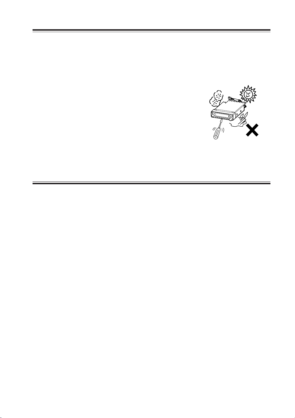
• Do not remove the case or touch the interior components.
Tampering can cause equipment trouble.
• Do not use or keep the transceiver where it is exposed to direct sunlight, dusty
places, or near sources of heat.
• Keep the transceiver away from TV's or other equipment when it interferes with reception.
• When transmitting for long periods of time at high
power, the transceiver might overheat.
• Turn the power off immediately if the transceiver
emits smoke or strange odors. Ensure the transceiver
is safe, then bring it to the nearest Alinco service
center.
Introduction
Thank you very much for purchasing this excellent Alinco transceiver. Our products
are ranked among the finest in the world. This radio has been manufactured with
state of the art technology and it has been tested carefully at our factory. It is designed to operate to your satisfaction for many years under normal use.
PLEASE READ THIS MANUAL COMPLETELY TO LEARN ALL THE FUNCTIONS THE PRODUCT OFFERS. WE MADE EVERY ATTEMPT TO WRITE
THIS MANUAL TO BE AS COMPREHENSIVE AND EASY TO UNDERSTAND
AS POSSIBLE. IT IS IMPORTANT TO NOTE THAT SOME OF THE OPERATIONS MAY BE EXPLAINED IN RELATION TO INFORMATION IN PREVIOUS CHAPTERS. BY READING JUST ONE PART OF THE MANUAL, YOU
RISK NOT UNDERSTANDING THE COMPLETE EXPLANATION OF THE
FUNCTION.
3
Page 7

1. New and Innovative Features
Your new radio features some of the most advanced functions and reliable engineering
available anywhere. The ALINCO design philosophy is focused on developing innovative usable features, including the following:
• Three different styles of display are available on a large LCD panel including frequency, channel number or 7 digit alphanumeric label. The dimmer (bright/dim) makes
it easier to read the display at night.
• Simple, clean layout of keys and knobs ensure convenient operation.
• High-quality materials are used throughout the product and a huge heat sink around the
chassis ensures stable and durable operation.
• Conventional or narrow FM mode can be selected.
• AM Air-band reception capability.
• 100 fully programmable memory channels with alphanumeric memory channel labels.
• A DATA port is located on the front panel for easy access to external accessory connections. A DSUB9 port is available on the rear to connect a PC for 1200/9600bps packet
operation.
• CTCSS, DCS and 4 different Tone-Bursts are standard for selective calling and repeater access worldwide.
• The Theft Alarm feature gives an extra measure of security for mobile installation.
• The transceiver has a cable clone capability.
• The optional EJ-41U board is available for data communications such as APRS® or
packet, without an external TNC.
4
Page 8
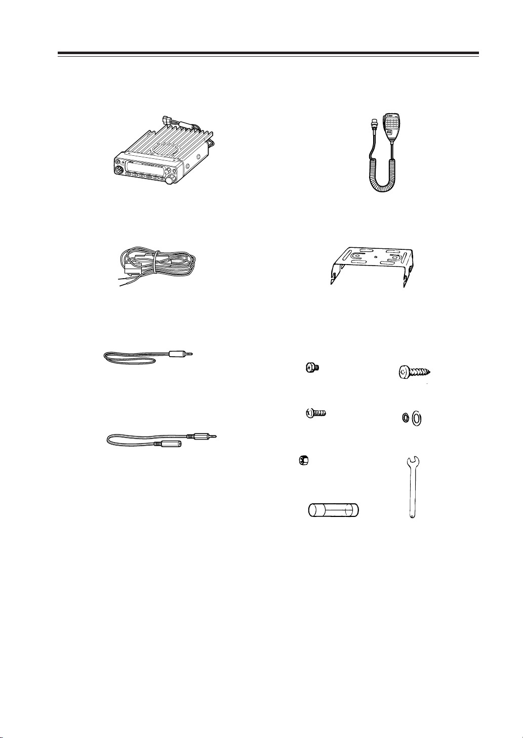
2. Standard Accessories
Carefully unpack to make sure the following items are found in the package in addition to this manual:
• Transceiver
• DC power cable with fuse holder (UA0038)
• Alarm cable A (with wire) (UX1259)
•
Alarm cable B (extension use) (UX1260)
• Microphone EMS-53 or EMS-57 (with
DTMF keypad)
• Mobile mounting bracket. (FM0078Z)
• Hardware kit for bracket
Black screws (M4*8mm)
4pcs. (AE0012)
Screws (M5*20mm)
4pcs. (AA0013)
Tapping screws
(M5*20mm) 4pcs. (AJ0003)
Washer (AZ0010)
S-washer (AZ0009)
Small (spanner) wrench.
(FM0079)
• Theft Alarm stickers 2pcs. (PR0454)
Hexagonal nut (M5) 4pcs.
(AN0002)
Spare fuses (a pair)
2pcs. (EF0005)
• Instruction manual (PS0349)
The standard accessories may vary slightly depending on the version you have purchased. Please contact
your local authorized Alinco dealer should you have any questions. ALINCO and authorized dealers are
not responsible for any typographical errors there may be in this manual. Standard accessories may
change without notice.
Warranty Policy:
Please refer to any enclosed warranty information or contact your authorized Alinco dealer / distributor
for the warranty policy.
5
Page 9
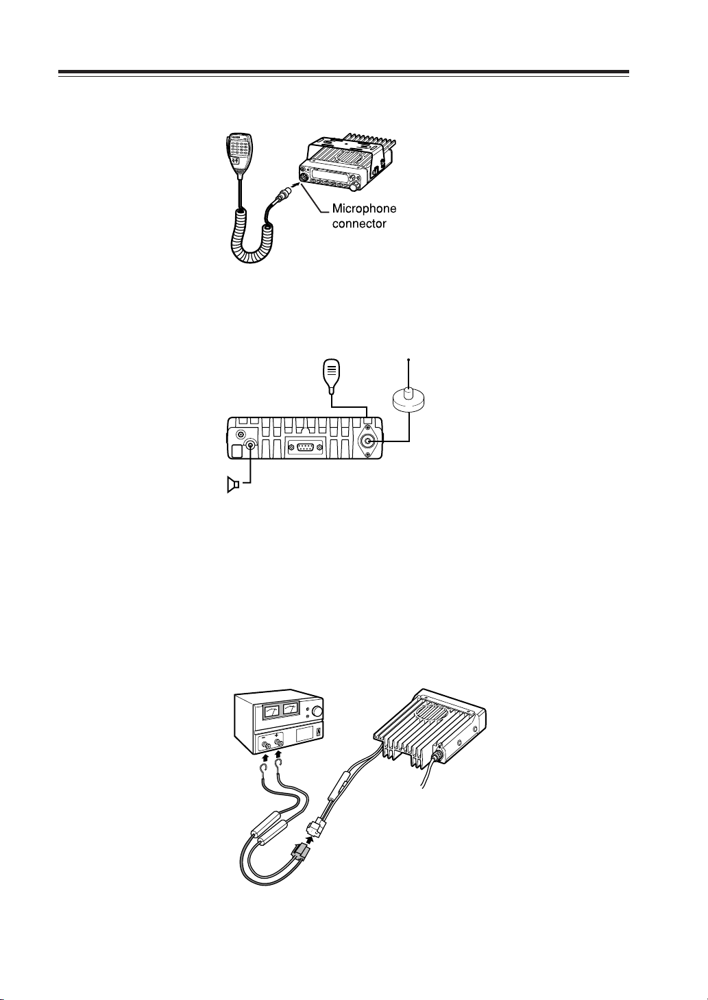
3. Initial Installation
Connect the microphone to the front panel of the transceiver.
Connect antenna port to a 50 ohm antenna that covers the two-meter band, using good quality
50 ohm coaxial cable.
Microphone
Antenna
External speaker
(if used)
rear panel
For a base station set up
The Transceiver requires a 12-13.8VDC negative grounded power source.
Use a regulated power supply capable of providing continuous current of 12A or more.
Power supplies that do not meet those specifications may cause malfunction and/or damage to the
radio and will void the warranty. Alinco offers excellent communication-grade power supplies as
optional accessories. Please contact your local authorized Alinco dealer.
DC
power supply
Black lead
2
Red lead
DC power cable
1
6
Page 10

3. Initial Installation
For a mobile station set up
Location
The transceiver may be installed in any position in your car, where the controls and microphone are
easily accessible and it does not interfere with the safe operation of the vehicle or the performance
of the set. If your vehicle is equipped with air bags, be certain your radio will not interfere with
their deployment. If you are uncertain about where to mount the unit, contact your vehicle's manufacturer.
Installing a Mobile Antenna
Screw-fixed
base
Magnet base
Use a 50 ohm coaxial cable to connect the antenna. Mobile antennas require an appropriate mounting base for proper installation and operation. For more information, see the documentation for
your antenna.
CAUTION: After installing your antenna, ensure that you have the best possible SWR reading.
High RF environments can cause severe damage to your unit. Ensure that you are not
in a high RF environment when operating the transceiver.
Installing the Transceiver
See the figure on the below.
Car body
Washer (M5)
Tapping screw
(M5 x 20 mm)
Mounting bracket
7
Page 11

3. Initial Installation
External power supply control & power lamp functions
ACC terminal
Ext. Power jack
DC cable
Be sure the vehicle has a negative-ground, 12VDC electric system before installation. Connect the
provided DC cable directly to the battery as shown below to minimize any possible ignition noise.
Be sure the vehicle has a large capacity battery as the use of the transceiver may overload the
electric system of the vehicle.
If the ignition-key on/off feature is desired (optional feature), use the optional EDC-37 (For direct
connection to the circuit on the vehicle) or EDC-36 (for a Cigar-Plug connection) cable. Connect
one of the cables between the ACC terminal or a Cigar-Plug that operates with the vehicle ignition
or ACC switch on the vehicle and EXT POWER jack on the rear side of the unit. (Note: In many
cars, the cigar-lighter plug is always powered. If this is the case, you cannot use it for the ignition
key on/off function.) If this option is selected, the unit can be turned on/off either manually or
automatically in accordance with the ignition key position:
Cigar-Plug connection
Battery
1. When the ignition key is turned to ACC or ON (Start) position with the radio turned
off, the power switch illuminates. The illumination will be turned off when the ignition key is turned to the off position. To turn on the unit, press the power switch
manually while it is illuminated (while ignition key is at ACC or ON position).
2. When the ignition key is turned to ACC or ON position with the radio's power switch
on, the unit turns on automatically and the power switch will be lit. Turn the ignition
key to OFF position or manually turn the power switch off to shut down the radio.
The power consumption when using the additional cable is 5mA.
For operation without this option, use the power switch to turn the unit on/off.
Power supply voltage display function
After connecting the transceiver to the power supply, the supply voltage can be confirmed by
pressing the SQL key together with the FUNC key. The supply voltage to the transceiver is then
seen on the display.
The transceiver will return to its normal operation when the power is switched OFF.
The display immediately changes as the voltage supply changes.
It also displays voltage during transmission.
IMPORTANT:
The range of the displayed voltage is only from 7V - 16VDC. Because the displayed value
is estimated, please use a voltmeter when a more precise reading is desired.
8
Page 12

4. Part Names and Functions
Front Panel
10
11
12
4 5
6
8
7
2
9
3
•Primary Functions
No.
Key Function
1PWR Power turns ON / OFF whenever switch is pressed.
2 Volume knob Adjusts the volume level.
3Dial
4 FUNC/SET Sets the function mode to access additional settings.
5 V/M/MW Switches between VFO mode and memory mode.
6 MHZ/SHIFT Changes the frequency in 1 MHz steps.
7
TS/DCS/LOCK
8 CALL/H/L Switches to CALL mode.
9 SQL/D Sets the squelch level
10
DATA Terminal
11
TX Light indicator
12
Mic. Connector
Changes the frequency, memory channel and scan direction.
Sets the tone squelch and DCS setting.
Used in clone and theft alarm functions.
Lights during transmission.
Connection port for supplied microphone.
1
•Functions which can be activated while F appears, after
pressing the FUCN Key.
No.
Key Function
4 FUNC/SET
5 V/M/MW Write in to memory channel.
6 MHZ/SHIFT Sets the shift direction and the offset frequency.
7
TSDCS/LOCK
8 CALL/H/L Switches between HI, MID, and LOW power transmission.
9 SQL/D
Confirms selection of other functions and exits the function mode.
Sets the key lock function.
Accesses the packet communication mode. / AM reception mode (DR-235T only)
9
Page 13

4. Part Names and Functions
Rear Panel
•
Functions that can be activated while pressing the FUNC Key
No.
Key Function
1PWR Reset to factory default settings.
5 V/M/MW Erase the memory.
6 MHZ/SHIFT Switches to wide / narrow mode reception.
7
TSDCS/LOCK
8 CALL/H/L Accesses the clone function mode.
9 SQL/D Accesses the power supply voltage indication mode.
Sets the auto dialer.
• Functions that require continuous pressing to be activated.
No.
Key Function
4 FUNC/SET When pressed for 2 seconds, accesses the set mode.
9 SQL/D
When pressed, within 1 second the monitor function is on.
21 4
No.
Key Function
1 Ext. Power jack Terminal for connecting optional EDC-37 for
2
External Speaker Terminal
3 DSUB-9 Connector Terminal where external TNC may be con-
4 Antenna Connector Connection for 50 ohm coaxial cable and
3
use with ignition key on/off function.
Terminal for optional external speaker
nected for packet use. With optional EJ-41U,
connects internal TNC to the computer.
antenna.
10
Page 14

Display
4. Part Name of Functions
12131416 15171819
11
10
1
2
3
No.
Key Function
1
SQL Appears when setting the squelch level.
2
M Appears when in memory mode.
3
4
.Decimal point
5
.Decimal point
6
.Decimal point
7
8
9 S-meter
Indicates the memory channel number in memory mode.
Appears when setting the theft alarm function.
Appears when setting the skip level.
Indicates the decimal point of frequency and the scanning function.
Indicates the frequency or memory name.
Appears when a signal is being received.
Indicates the relative signal strength level of transmission / reception.
5 6 7
4
9
8
10 Appears when in packet mode.
11 key lock Appears when setting the key lock.
12 DCS Appears when setting the DCS.
13 Appears when setting the tone squelch.
14 +- Appears when setting the shift.
15 A Appears during AM reception.
16 Nar Appears when in narrow band reception mode.
17 Lo Appears when transmission power is set to LOW.
18 Mi Appears when transmission power is set to MID.
19 Appears when FUNC Key is pressed.
11
Page 15

4. Part Names and Functions
Microphone
Standard Option
No.
Key Function
1UP
2 DOWN
Increase the frequency, memory channel number, or setting value.
Decrease the frequency, memory channel number, or setting value.
3 PTT Press the PTT(Push-To-Talk)key to transmit.
4 DTMF DTMF tone keys
DTMF / REMOTE
5
Set to DTMF when you don’t want to operate remote con-
trol functions. So that DTMF keys do not function except
Switch
during transmit to send DTMF codes manually.
6 Lock Switch Locks out the UP and DOWN keys.
7MIC Speak here during transmission.
12
Mic. Connector Diagram (While looking in the front view of the con-
nector)
GND
MIC
PTT
DOWN
1
7
2
3
6
8
5
4
MIC GND
Remote control
DC 5V
UP
Page 16

5. Basic Operations
PWR key
Turning the unit on and off
Press the power switch or turn the ignition key to ACC or ON
position according to the option selected during installation.
Press the power switch again or turn the ignition key to OFF
position to turn off.
Audio Volume level setting
Rotate the VOL knob clockwise to increase the audio level,
counterclockwise to decrease. Set it at the desired level.
Squelch level setting
A squelch eliminates white-noise (the background noise when
a signal is not received).
Higher level settings will keep the squelch “closed” more
tightly for quieter monitoring, but weak signals will not be
heard. Lower settings allow weaker signals to “open” the
squelch but noise may also cause it to open.
1. Press SQL key. SQL icon appears on the dis-
play and the squelch level will be shown at the
position where the memory number is displayed. 21 levels, between 0 and 20, are available. “0” is the lowest setting.
2. By rotating the main dial or by using the UP/
DOWN keys on the microphone, adjust the
squelch to the desired level. To return to normal use, press PTT or any key on the front
panel; or if there are no operations within 5
seconds, the unit will store the setting and will
return to its original status.
Minimum
volume
Squelch level
Maximum
VOL knob
volume
The new squelch level will be stored in the CPU until another
adjustment is done.
13
Page 17

5. Basic Operation
VFO mode
VFO tuning is set as a default mode at the factory. VFO (variable frequency oscillator) allows you to change the frequency
in accordance with the selected channel step as you rotate the
main dial or by using the UP/DOWN keys on the microphone.
VFO mode is also used to program the data to be stored in the
memory channels or to change the parameter settings of the
transceiver.
1. Identify the current mode by checking the dis-
play. If “M” or “C” icon is NOT displayed on
it, the unit is already in the VFO mode.
2. Otherwise press “V/M” keys until those icons
are gone.
[Change frequency by the channel step]
Rotate the main dial clockwise to increase the frequency, counterclockwise to decrease. The UP/DOWN keys on the microphone act in the same way.
Frequency
decrease
VFO mode
Frequency
increase
[Change frequency by 1 MHz step]
This will enable a quick change of frequency in 1 MHz steps:
1. Press MHz key. The digits after 100 kHz will
disappear from the display.
2. Follow the same sequence as above to change
the value.
Dial
14
Page 18

Changing the channel step
1. Be sure the unit is in VFO mode. Refer to page
21 to enter into the SET mode.
5. Basic Operation
2. Select the channel step parameter setting using
the tuning knob. The current channel step will
be displayed as below.
3. Press PTT or any one of the keys except SQL
on the front panel to enter the desired step into
the transceiver’s memory. The display will then
return to the original status.
Please note that settings below 10 kHz may be automatically
corrected according to the selected step.
REPEATER (DUPLEX) Operation
Shift Direction and Offset frequency setting
Conventional repeaters are operated in the DUPLEX mode.
It receives an incoming signal (UP-LINK) on one frequency
and re-transmits on another (DOWN-LINK). The difference
between these two frequencies is called the offset frequency.
If the UP-LINK frequency is higher than the DOWN-LINK
frequency, the direction is positive, and if it is lower, the shift
direction is negative. The offset is variable between 0 to 99.995
MHz on this unit.
Display for channel step
at-600 kHz
Press the F key. While the F icon stays on the display, press
MHz key. The display shows the current status of shift direction and offset frequency. The default value is 0.60 MHz (600
kHz) in the negative direction. Press MHz key until the desired offset direction is set. If SIMPLEX mode (without changing transmit and receive frequency) is desired, select the position where both - and + icons disappeared.
Shift release
1. Rotate the dial or use UP/DOWN keys on the microphone to change the shift fre-
quency. It changes in accordance with the channel step setting.
2. In this mode, if the F key is pressed again, the offset frequency can be changed in
1 MHz steps for faster setting.
3. Press PTT or any key except F or MHz on the front panel to return to the original
status.
15
Page 19

5. Basic Operation
CTCSS / DCS setting
Many repeaters require a CTCSS tone or a DCS code encode setting as a “key” to access the
system, so-called “selective-calling”. Sometimes, CTCSS or DCS decode features are used on the
output of a repeater so they can be used as a squelch. In this mode, regardless of the main squelch
status, the audio can be heard ONLY when the matching tone/code signal is received. The combination of CTCSS squelch and DCS function is not available; only one or the other may be used for
a given memory channel.
1. Press TS/DCS key. The current setting will be
displayed with T/SQ/DCS icons and relative
frequency/code. Press the same key to select
T
88.5
The original status
T/SQ
88.5
DCS
023
T/SQ/DCS setting.
2. The numbers (such as 88.5) represent the CTCSS frequency in Hz. When it is dis-
played with the T icon only, the unit transmits the sub-audible tone while the PTT is
pressed (encode) and the repeater access is enabled (assuming the repeater is using
88.5).
3. Press the same key again so that the SQ icon shows up on the display. This is the
CTCSS decode frequency. This enables CTCSS squelch (or Tone Squelch, TSQ).
4. Press it again so that the 3-digit number and DCS icon is displayed. This is the DCS
code, and it enables DCS encoding and decoding.
For 2 - 4, rotate the main dial or press the UP/DOWN keys to change tone or code. Press any key
(Except TS/DCS, UP/DOWN keys) to enter the setting and return to original status. The T/SQ/
DCS icon will remain on the display to show the current status. To exit, simply use the TS/DCS key
and press it until the relative status icon T/TQ/DCS disappears.
The CTCSS encoding and decoding frequencies may be set differently. The encode setting frequency automatically relates to the decode setting, but decode setting does not affect encode. The
standard set of 39 different CTCSS tones are available as shown on the chart below. DCS encode/
decode cannot be separated and are selectable from 104 codes as shown below.
67.0 69.3 71.9 74.4 77.0 79.7
82.5 85.4 88.5 91.5 94.8 97.4
100.0 103.5 107.2 110.9 114.8 118.8
123.0 127.3 131.8 136.5 141.3 146.2
151.4 156.7 162.2 167.9 173.8 179.9
186.2 192.8 203.5 210.7 218.1 225.7
233.6 241.8 250.3
CTCSS Tone Frequency(Hz)
NOTE: Depending on the deviation level of the incoming DCS coded-signal, your radio may not open the DCS
squelch. If this occurs, return to DCS setting mode and press the CALL key. A decimal point appears on
the 10 MHz order; then set the desired code. This setting can also be stored in a memory channel.
023 025 026 031 032 036 043 047 051 053 054
065 071 072 073 074 114 115 116 122 125 131
132 134 143 145 152 155 156 162 165 172 174
205 212 223 225 226 243 244 245 246 251 252
255 261 263 265 266 271 274 306 311 315 325
331 332 343 346 351 356 364 365 371 411 412
413 423 431 432 445 446 452 454 455 462 464
465 466 503 506 516 523 526 532 546 565 606
612 624 627 631 632 654 662 664 703 712 723
731 732 734 743 754
DCS Codes
16
Page 20

5. Basic Operation
Memory Mode
The memory mode on this transceiver provides up to 100 channels (0-99), 1 call (quick recall ch)
and a pair of program-scan “edge memory” channels for quick, easy access to the preprogrammed
frequencies with different parameter settings.
1. Press V/M key. M icon appears on the display
to indicate that the unit is in the memory mode.
Repeat to switch the mode between VFO and
memory.
2. In memory mode, rotate the main dial or press
UP/DOWN keys to change the memory channel number.
Memory mode
3. To change the number by units of 10, press
FUNC and rotate the main dial or press UP/
DOWN keys while F icon is on the display.
[Memory programming]
1. Return to VFO mode by pressing V/M key. Re-
ferring to the list below for the programmable
parameters, program in the VFO mode to the
desired frequency and settings to be stored later
in the memory.
2. When all the settings are complete, press FUNC
key. The F, and M icons appear and a memory
channel number will be indicated on the
display.
3. Rotate the main dial or press the UP/DOWN
keys to select the desired memory channel number into which the current VFO settings will be
copied. An empty channel is shown with a flashing M icon. It may be a good practice to “allocate” memory channels in order, such as 0-9
for local repeaters, 10-19 local simplex, 20-49
repeaters within the area, 50-79 for repeater reserve, 80-98 simplex reserve. It makes references easier for the operation and future modifications of the memory channels.
Memory channel
during the unregistered channel
17
Page 21

5. Basic Operation
4. While F icon is on the display, press MW key.
5. To program the CALL channel (quick recall)
6. To delete a programmed channel, select it in
7. To undo delete, repeat 6. However, the Undo
The VFO settings are copied to the memory
channel and a beep will sound. The memory
channel can be over-written if a previously programmed channel is selected (the memory
channels shown with a stable M icon).
select the channel shown with CH-C on the display. Save Ch99 to store the setting used for
the Alarm operation, which will be explained
later. Use PL and PH for Program scan setting,
which will be explained in the advanced operations chapter.
memory mode, press FUNC key then press the
MW key while F icon is on. The memory is deleted and a beep sounds. The M icon starts flashing showing that this channel is now empty.
function becomes impossible once the channel
or the mode is changed.
[Programmable data in the memory channel]
Some features will be explained later, so please read this instruction manual thoroughly prior to
programming memories.
Memory channels including 0 - 99 and CALL can store following:
• Frequency
• Shift frequency
• Shift direction
• CTCSS tone both encode and decode
• Tone Squelch setting
• DCS code both encode and decode
• DCS squelch setting
• Scan skip channel
• Busy Channel Lock Out setting
• Priority monitoring frequency (PC programming required)
• Normal/Narrow FM width
• AM air-band receive
NOTE: Only the frequency can be stored in PH and PL channels to determine the edges of the program
scan range.
18
Page 22

5. Basic Operation
CALL mode
This is a memory mode that allows the transceiver to quickly recall the assigned memory channel
by simply pressing the CALL key, regardless of the current status of the unit.
1. Press CALL key. The C icon appears on the
display and the transceiver enters the CALL
mode. In this mode, the main dial or the UP/
DOWN keys cannot change the frequency or
memory channels.
2. Press CALL key again or press V/M key to exit
CALL mode.
3. No scan functions are available in CALL mode.
To store a desired setting in the CALL channel, follow the memory mode programming instructions and assign your selected settings to memory channel C. The call channel can be modified but
cannot be eliminated or hidden.
To receive signals
• Be sure to have the unit connected to the appropriate antenna, powered on, set the audio volume and
squelch level properly.
• Select the desired receiving frequency or browse frequencies to listen to ongoing communications. The
S-meter shows relative signal strength between BUSY and FULL when the transceiver detects an incoming
signal.
• If the S-meter indicates an incoming signal but nothing is heard from a speaker, check audio level, squelch
level, and CTCSS/DCS decoding status, which are explained elsewhere in this manual.
• A Monitor function is available to receive weaker signals. Press and hold SQL key for more than 1 second.
Regardless of the level setting of the squelch, it will be opened and the BUSY icon turns on the display.
Press any key on the front panel to exit.
19
Page 23

5. Basic Operation
To transmit
1. Select the desired frequency. Be sure that you
are authorized to operate on the selected frequency. Check the system and monitor the fre-
quency to make sure that you are not going to
disturb any ongoing communications.
2. Select the output power. Press FUNC key and
then press CALL key while F icon is on the
display. As the CALL key is pressed, the output power changes among 3 levels. The Lo icon
stands for LOW power setting, Mi for MEDIUM power. When the transceiver is set at
HIGH power, no icon will appear. The output
power level cannot be changed during transmission.
3. Default setting is High power. Press the PTT
key on the microphone to transmit, release it to
receive. During transmission, the relative power
output is shown on the RF meter as:
LOW power = 2 segments
MID power = 3 segments
HIGH power = 5 segments.
LOW power
MID power
20
HIGH power
4. If operating from a vehicle, do not transmit for
extended periods without running the engine,
to avoid battery drainage. Check the battery
voltage often. The lights, windshield wipers,
stereo system, air-conditioner, defogger and
other accessories drain the battery’s power considerably. When those accessories are turned
on, reduce the output power or turn off one or
more accessories to avoid the battery becoming overloaded. Watch the road when driving.
Check local regulations that may pertain to the
use of a transceiver when driving.
Page 24

6. Parameter Setting Mode
IMPORTANT: Please read the following pages thoroughly prior to the change of any parameters.
THE PARAMETERS CANNOT BE SET WITHOUT ENTERING THE SET MODE.
By entering the Parameter Setting mode, some of the radio’s operating parameters can be changed
to suit your application. The following is the Selectable Parameters’ Menu.
Note: The Alphanumeric Channel Tag setting will not appear in the menu until memories have been programmed
first!
To use the Parameter Setting mode
1. Press FUNC key for more than 2 seconds to
enter the Parameter Setting mode.
Use SQL key or UP/DOWN keys to select
menu.
2. Rotate the main dial to select the desired set-
ting.
3. Press SQL or UP/DOWN keys again to enter
the selected setting into the radio’s memory. The
transceiver is now ready for additional Parameter adjustments.
Default setting
4. Press any key OTHER than SQL/UP/DOWN
to exit the Parameter mode. The only exception is the Channel Tag setting which accepts
only PTT, FUNC, MHz and TS/DCS keys to
exit.
Details of the features in Menu
Please refer to “Parameter Setting Mode” for setting operations. The operation procedures of some of the features are explained later in detail.
Parameters Setting Mode
STP-5 Channel Step setting
TIMER Scan type (time scan/busy scan)
BEEP-ON Beep sound ON/OFF
TOT-OFF Time-Out-Timer ON/OFF
TP-OFF TOT penalty ON/OFF
APO-OFF Auto-Power-Off ON/OFF
TB-1750 Tone-Burst Frequency setting
BCLO-OF Busy-Channel-Lock-Out ON/OFF
SCR-OFF Theft Alarm ON/OFF
A
LAMP-H
Alphanumeric Channel Tag setting
Dimmer (LCD illumination) High/Low
21
Page 25

6. Parameters Setting Mode
Channel Step setting:
This is to select the channel step to be used in the VFO mode.
Refer to the chart below for the relation of the actual step
frequency and how it is displayed.
Scan Type
This is to select the scan resume condition. TIMER setting
allows the radio to resume scanning after 5 seconds, regardless of the signal receiving status. BUSY setting resumes scanning when the received signal is gone. The scan mode is explained later.
Beep Sound
BEEP-ON setting enables a beep that sounds after certain keys
are touched and/or setting is done. BEEP-OF shows that the
beep function is off.
22
Page 26

6. Parameters Setting Mode
Time-Out-Timer
The TOT feature is popular in repeater systems. It prohibits the users from transmitting on the
repeater after a certain period of time has elapsed. By setting this function and activating it according to the repeaters’ requirement, the radio alerts the user by a beep 5 seconds prior to time-out.
When the time is expired, transmitting stops and the transceiver automatically returns to receiving
mode. This avoids the repeater going into its TOT mode. Until the PTT is released once and pressed
again, the transceiver will not transmit.
1. In this Menu the default display shows TOT-
OFF.
2. Rotate the main dial to select time-out time.
The display should change as shown. The number followed by TOT is the time-out time in
seconds.
3. The TOT feature is selectable up to 450 sec-
onds (7.5 minutes).
during the setting time of 60 seconds
TOT Penalty
When the transmission is shut down in the TOT mode, this function prohibits another transmission
for a selected time period.
1. During the TOT penalty period, the beep sounds
when the PTT is pressed but the radio does not
transmit.
2. If the PTT is continuously pressed over both
TOT and the TOT penalty period, this function
will be automatically cancelled.
3. Default setting is TP-OFF. Rotate the main dial
to select the penalty time, up to 15 seconds.
during the setting time of 5 seconds
23
Page 27

6. Parameters Setting Mode
APO-Auto Power OFF
This feature will automatically shut off the transceiver. It is useful for mobile operation to avoid
draining the car battery. If there is no activity or use of the radio, it will turn off automatically after
30 minutes followed by a beep sound.
1. Default is APO-OFF.
2. Rotate dial to select APO-ON to activate the
function.
during the ON setting
Tone-Burst Frequency
This is to access Tone-Burst repeaters which require a certain pitch of audible tone to activate
“sleeping” repeaters. Usually, a repeater system does not require the tone once the repeater is
activated.
1. The default is TB-1750, which is 1750 Hz tone.
2. It is selectable from 1750, 2100, 1000, 1450 Hz.
during the 1750 Hz frequency
See ADVANCED OPERATION chapter for operation.
Busy-Channel-Lock-Out
This function prohibits transmission as long as there is a signal on the receiving frequency.
The default is BCLO-OF, which is the off position. By activating this function, the radio transmits
only when:
1. No signal is received (BUSY icon is gone) on
the receiving frequency.
2. Tone-squelch is opened by the corresponding
CTCSS tone of the receiving signal.
3. As above, with DCS code.
Otherwise a beep sounds but the unit does not transmit even
when the PTT is pressed.
during the ON setting
Theft Alarm
Default is SCR-OFF. Select ON or DLY to activate the function. When the SCR-ON is selected, 100 MHz and 100 kHz
order decimal points will appear on the display.
The operation of this transceiver feature is explained later.
lights up lights up
24
Page 28

6. Parameters Setting Mode
Alphanumeric Tag
The memory channels stored in the memory-mode can be displayed with an alphanumeric tag
instead of the default frequency display. Program the memory channel first.
There are 67 characters available including A-Z, 0-9.
1. Enter the set mode while the unit is in memory
mode.
2. Select alphanumeric tag setting by rotating the
main dial or pressing the UP/DOWN keys. The
display shows [A] flashing.
3. Rotate the main dial to select a character. Press
the V/M key. The character stops flashing and
is entered.
4.
The same flashing character appears next to it,
ready for the next character to be entered. Repeat the same sequence, up to seven characters.
5. To delete all characters during programming
press [CALL] key.
6. To exit after setting is done, press one of the
following keys: PTT, FUNC, TS, DCS.
After programming, the alphanumeric tag will be displayed on the designated channels, instead of
the frequency, when in memory mode. The memory channel number and other status icons will
also be displayed. If you wish to see the programmed frequency, press FUNC and it will be displayed for 5 seconds. To return to the alphanumeric display, wait 5 seconds or press any key.
Pressing any key followed by FUNC returns to normal operation, regardless of the display status.
IMPORTANT: This function cannot be enabled without programming the memories.
Dimmer
The display illumination can be dimmed.
1. [LAMP-H] is displayed as default.
2. Rotate the dial to choose the brighter (H) or
darker (L) position.
25
 Loading...