

Page 1

Dear Client,
Thank you for choosing Alfa Romeo.
Your
Alfa 166 has been designed to guarantee the safety, comfort and driving pleasure typical of Alfa
Romeo.
This booklet will help you to get to know the characteristics and operation of your vehicle.
The following pages contain all the indications necessary for you to be able to maintain the high standards of
performance, quality, safety and respect for the environment which characterise this
Alfa 166.
The Warranty Booklet also contains the regulations, the warranty certificate and a guide to the services offered by
Alfa Romeo - services which are essential and precious because, when you purchase an Alfa Romeo you are not
only acquiring a car, but the tranquillity that comes from knowing that an efficient, willing and widespread organization is at your service for any assistance problems you may have.
What’s more every single component of the
Alfa 166 is fully recyclable. At the end of your car’s useful
lifespan any Alfa Romeo dealer would be pleased to make arrangements for your car to be recycled and nature
benefits in two ways: there’s no pollution from waste disposal, and the demand for raw materials is reduced.
Have a good trip.
1
Page 2

Any queries concerning servicing should be forwarded to the showroom from which the vehicle was purchased,
the subsidiary company or to our branch offices or associated companies.
WARRANTY BOOKLET
The Warranty Booklet is delivered together with every new vehicle and contains the regulations tied to the services
given by Alfa Romeo Services and to the warranty conditions.
Correctly carrying out the scheduled services specified by the manufacturer is the best way to maintain the performance, safety characteristics and low running costs of your vehicle. It is also necessary to maintain warranty
cover.
“Service” guide
This contains the Alfa Romeo Authorized Services. The services can be recognized by the presence of the Alfa
Romeo badge and logo.
The Alfa Romeo organization in Italy can be found in the telephone book under the letter “A” Alfa Romeo.
Not all the models described in this booklet are available in all countries. Only some of the fittings described in this booklet are
fitted as standard to the vehicle. The list of available accessories should be requested from Alfa Romeo Dealers.
2
Page 3
3
VERY IMPORTANT!
FUEL CAPACITY
Petrol engines: only use unleaded petrol with no less than 95 R.O.N.
JTD engines: only use Diesel fuel for motor vehicles that meet European Specification EN590.
K
STARTING THE ENGINE
Petrol engines with mechanical transmission: engage the handbrake; set the gearshift lever to neutral; fully depress
the clutch without pressing the accelerator, then turn the ignition key to AVV and release it as soon as the engine has started.
Petrol engines with automatic electronic transmission (Sportronic): make sure that the handbrake is engaged and that the gearshift lever is at P; keep the brake pedal fully depressed without pressing the accelerator; then turn
the ignition key to AVV and release it as soon as the engine has started.
JTD engines with mechanical transmission: engage the handbrake; set the gearshift lever to neutral; fully depress
the clutch without pressing the accelerator; turn the ignition key to MAR and wait for the
m
warning light to go off, then
turn the ignition key to AVV and release it as soon as the engine has started.
JTD engines with automatic electronic transmission (Sportronic): make sure that the handbrake is engaged and that the gearshift lever is at P; keep the brake pedal fully depressed without pressing the accelerator; turn the ignition key to MAR and wait for the
m
warning light to go off, then turn the ignition key to AVV and release it as soon
as the engine has started.
PARKING ON FLAMMABLE MATERIAL
While working, the catalyst develops a very high temperature. Do not park the car over grass, dry leaves, pine needles or
any other inflammable materials: risk of fire.
Page 4

4
ACCESSORY ELECTRICAL DEVICES
If after purchasing the car you wish to install accessories that need an electrical supply (with the risk of gradually draining
the battery), contact Alfa Romeo Authorised Services who will assess the overall electrical absorption and check whether the
car system is able to withstand the load required.
쇵
CODE CARD
Keep it in a safe place, not in the car. It is advisable to always keep the electronic code on the CODE card with you in case
emergency starting is necessary.
SCHEDULED SERVICING
Correct maintenance makes it possible to preserve vehicle peformance levels and safety, respect for the environment and
low running costs unaltered over the course of time.
THE OWNER HANDBOOK...
…you will find important information, advice and warnings for correct use, driving safety and vehicle maintenance over
time. Pay particular attention to the symbols
"
(personal safety)
#
(protecting the environment)
â
(vehicle safety).
RESPECTING THE ENVIRONMENT
The vehicle is fitted with a system that allows continuous diagnosis of the components correlated with emissions to ensure
better respect for the environment.
Page 5
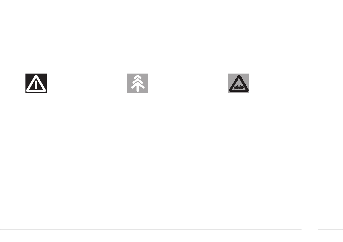
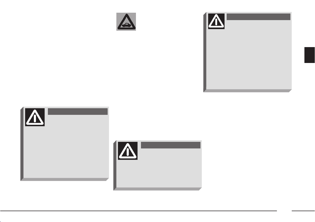
Warning: partially or fully ignoring
these rules may lead to serious injury.
This indicates the correct procedures to be
followed to prevent the vehicle from damaging the environment.
Warning: partially or fully ignoring these
rules may lead to serious damage being
caused to the vehicle which, in some circumstances, may cause forfeiture of the
warranty cover.
THE SYMBOLS USED IN THIS BOOKLET
The symbols illustrated in these pages show the subjects which should,
in particular, be closely studied.
VEHICLE
SAFETY
PROTECTING
THE ENVIRONMENT
PERSONAL
SAFETY
5
Page 6
6
SYMBOLS
Special coloured labels have been attached near to or actually
on some of the components making up your Alfa 166.
These labels bear symbols that remind you of the precautions to
be taken as regards that particular component.
A list of the symbols to be found on your Alfa 166 is
given below, with the name of the component to which it relates
at the side of it.
These symbols are divided into the following four categories:
danger, prohibition, warning and obligation.
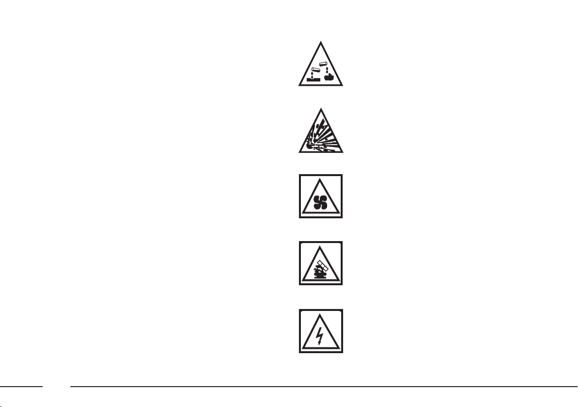
DANGER SYMBOLS
Battery
Explosion.
Fan
May cut in automatically when the engine is off.
Expansion tank
Do not remove the cap when the coolant is boiling.
Battery
Corrosive fluid.
Coil
High voltage.
Page 7
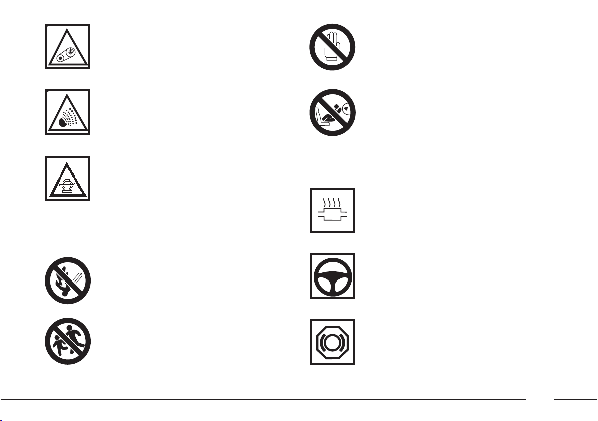
WARNING SYMBOLS
Power steering
Do not exceed the maximum fluid level in the
reservoir. Use only the recommended fluid; see
table “Specifications of fluids and lubricants”.
Brake circuit
Do not exceed the maximum fluid level in the
reservoir. Use only the recommended fluid; see
table “Specifications of fluids and lubricants”.
Catalytic converter
Do not park over inflammable materials. See paragraph “Protecting emission reducing devices”.
Belts and pulleys
Moving parts; keep limbs and clothing away.
Jack
See the owner Handbook.
Climate control tubing
Do not open.
Gas under high pressure.
PROHIBITION SYMBOLS
Battery
Keep away from children.
Battery
Keep away from naked flames.
Heat shields - belts - pulleys - fan
Do not touch.
Passenger’s Air bag
Do not install a child’s seat on the front passenger’s seat with operational air bag.
7
B
A
R
I
G
A
Page 8
OBLIGATION SYMBOLS
DIESEL
Diesel vehicle
Use only diesel fuel.
Battery
Protect your eyes.
Battery - Jack
See the Owner Handbook.
Expansion tank
Use only the recommended fluid; see table “Specifications of fluids and lubricants”.
Windscreen wiper
Use only the recommended fluid; see table
“Specifications of fluids and lubricants”.
Engine
Use only the recommended lubricant; see table
“Specifications of fluids and lubricants”.
Unleaded petrol vehicle
Use only unleaded petrol with RON 95.
8
Page 9

GETTING TO KNOW YOUR CAR
GETTING THE BEST OUT OF YOUR CAR
IN AN EMERGENCY
CAR MAINTENANCE
TECHNICAL SPECIFICATIONS
RIGHT HAND DRIVE VERSION
INDEX
CONTENTS
9
Page 10

10
The text, illustrations and specifications given herein are based on
the vehicle at the date of going to press.
In our ongoing striving to improve our products, Alfa Romeo may
introduce technical changes during production, therefore the specifications and equipment on board may be altered without prior
notice. Contact the factory sales network for detailed information.
Page 11

11
Sit comfortably in your vehicle and carefully read through the following pages.
You will immediately recognize the parts described and rapidly get
to know the controls and devices fitted to your vehicle.
STR (SPORT THROTTLE RESPONSE) SYSTEM................................................. 63
CONSTANT SPEED REGULATOR (CRUISE CONTROL)................................... 64
PARKING SENSORS............................................................................................... 67
INSTRUMENT PANEL............................................................................................. 68
CLIMATE CONTROL................................................................................................ 81
CLIMATE CONTROL UNIT..................................................................................... 83
ADDITIONAL HEATER............................................................................................ 88
CONTROLS................................................................................................................ 90
ELECTRONIC AUTOMATIC GEARBOX (SPORTRONIC) ................................ 93
INTERNAL FITTINGS.............................................................................................. 102
SUNROOF................................................................................................................. 108
LUGGAGE COMPARTMENT.................................................................................. 110
BONNET .................................................................................................................... 112
HEADLIGHTS............................................................................................................ 113
ENGINE CONTROL SYSTEM (EOBD)................................................................. 116
ABS............................................................................................................................. 117
VDC AND ASR SYSTEMS....................................................................................... 120
SOUND SYSTEM...................................................................................................... 124
REFUELLING ............................................................................................................ 125
FUEL CUT-OFF SWITCH ........................................................................................ 128
ENVIRONMENTAL PROTECTION......................................................................... 130
DASHBOARD................................................................................................ page 12
ALFA ROMEO I.C.S. SYSTEM: CONTROLS ON STEERING WHEEL ........... 14
THE ALFA ROMEO CODE SYSTEM...................................................................... 16
ELECTRONIC ALARM.............................................................................................. 22
REMOTE CONTROL DOOR LOCKING SYSTEM................................................ 26
IGNITION DEVICE................................................................................................... 26
DOORS....................................................................................................................... 28
SEATS......................................................................................................................... 31
STEERING WHEEL ADJUSTMENT....................................................................... 36
ADJUSTING THE REAR-VIEW MIRRORS.......................................................... 36
POWER WINDOWS................................................................................................ 38
SEAT BELTS ............................................................................................................... 40
CARRYING CHILDREN SAFELY............................................................................ 45
FRONT AND SIDE AIR BAGS............................................................................... 50
LIGHT SWITCHES & STEERING WHEEL LEVERS ............................................ 57
GETTING TO KNOW YOUR CAR
Page 12
12
fig. 1
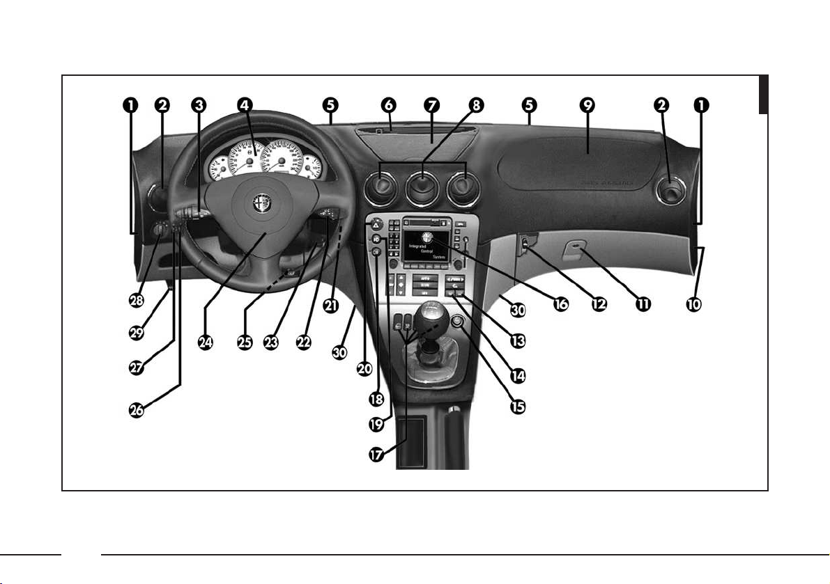
DASHBOARD
A0D0002m
Page 13

13
1 Air ducts for side window outlets.
2 Side air vents.
3 Light switch lever (high beam, flash-
ing, direction indicators and controls
for Cruise Control (automatically
keeping a set speed) (if present).
4 Instrument cluster.
5 Outlets for windscreen.
6 Upper outlet.
7 Oddments compartment.
8 Centre air vents.
9 Passenger’s air bag.
10 Manual passenger’s side Air bag
deactivation switch.
11 Glove box.
12 Boot opening button (in glove box).
13 Button for rearscreen defrosting,
door mirrors and resistances at base
of windscreen (if present).
14 Button for windscreen/front side
windows and door mirrors
defrosting, rearscreen heating,
resistances at base of windscreen (if
present).
15 Cigar lighter.
16 Alfa Romeo I.C.S. (INTEGRATED
CONTROL SYSTEM): RDS radio,
computer on board (TRIP), climate
control, clock and outside/inside
temperature, GSM phone and
navigation system (if present).
17 Buttons for central locking, fuel flap
opening, switching off the ASR
function of the VDC system switching
on the STR system (if present).
18 Rear fog guard switch.
19 Front fog light switch.
20 Hazard warning light switch.
21 Inside temperature sensor.
22 Windscreen wiper/washer control
lever and rain sensor (if present).
23 Ignition switch (ignition device).
24 Driver’s air bag and horn.
25 Lever for releasing/locking adjustable
steering wheel.
26 Instrument lighting adjustment.
27 Headlamp aiming device control
(except versions with gas discharge
headlights).
28 Outside lights switch.
29 Bonnet opening lever.
30 Front floor air outlets.
Page 14
14
ALFA ROMEO I.C.S.
SYSTEM
CONTROLS ON STEERING
WHEEL
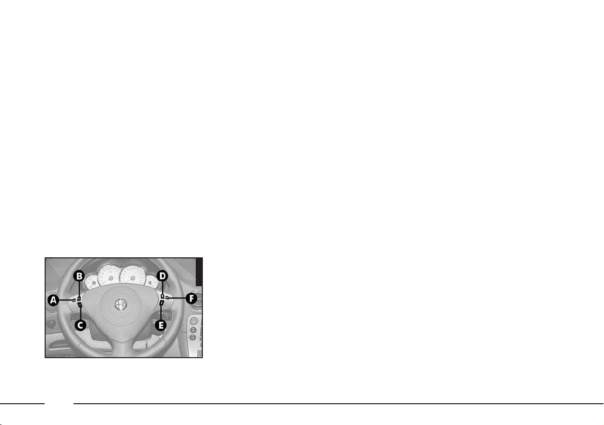
(fig. 2)
(on request for versions/markets
where applicable)
The main audio functions (AUDIO) of
the Alfa Romeo I.C.S. system are repeated on the steering wheel, which facilitates control.
A - Mute button
B - Volume highering button
C - Volume lowering button
D - Multifunction key:
– Radio: call preset stations (1 to 6)
– CD player: select next track
E - Multifunction key:
– Radio: call preset stations (6 to 1)
– CD player: select previous track
F - Radio frequency range select button
(FM-A, FM-B, FM-AS, MW, LW) and available audio sources (Radio – Cassette
player –CD player).
Mute key (A)
To turn the Mute function on, briefly
press button (A): the volume will lower
gradually.
To turn the Mute function off, briefly
press button (A) again. The volume will
higher gradually returning to the previously set value.
The Mute function is also turned off
pressing one of the volume adjustment
keys (B) or (C): in this event volume is
directly changed.
When the Mute function is on, all the
other functions can be used and if traffic
information is received the message ignores the Mute function.
A0D0004m
fig. 2
Page 15

15
Volume adjustment keys (B) and
(C)
Press (B) to increase volume and (C)
to lower it.
Pressing briefly the key volume change
is gradual by steps. Pressing it longer volume change is faster.
If volume is changed during a traffic bulletin, the new value is kept only for the
bulletin in progress.
Multifunction keys (D) and (E)
Multifunction keys (D) and (E) shall be
used for tuning preset radio stations, for
backward rewinding and for selecting
next/previous CD track.
Press (D) to select stations from 1 to 6,
or to play next CD track.
Press (E) to select stations from 6 to 1,
to play previous CD track.
Frequency range and audio
source select key (F)
To cyclically select the frequency ranges
and audio sources, briefly and repeatedly
press key (F).
The frequencies/sources available are:
FM-A, FM-B, FM-AS, MW, LW, CC*,
CD**.
(*) Only if the cassette is inserted.
(**) Only if a CD is inserted.
Page 16
16
1035PGSm
fig. 5
THE ALFA ROMEO
CODE SYSTEM
To increase protection against attempted
theft, the car is fitted with an electronic
engine lock system (Alfa Romeo CODE)
certified in accordance with EC Directive
95/56 which is activated automatically
when the key is removed from the ignition.
In fact the grip of each key contains an
electronic device which modulates the radio frequency signal transmitted when the
engine is started by a special aerial incorporated in the ignition switch.
This modulated signal is the “password”
by which the control unit recognises the
key and only in this condition can the engine be started.
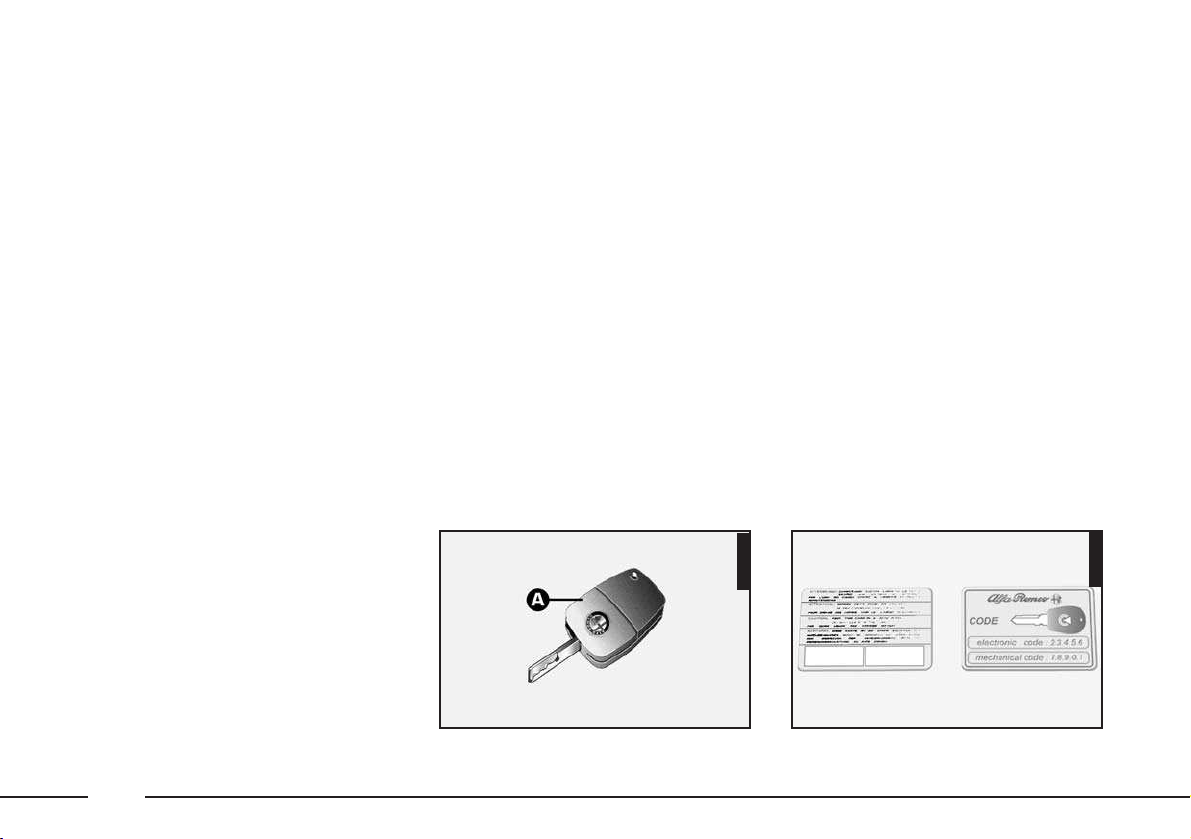
THE KEYS
The car is provided with the key (A-
fig. 4) with metal insert with power-as-
sisted opening, remote control for opening
the boot and remote control for unlocking/locking the doors and electronic alarm
(where applicable).
The key operates:
– the ignition
– door locks
– boot lock
– glovebox lock
– remote door locking/unlocking sys-
tem
– alarm system (optional for versions/
markets where applicable)
– deactivation of the passenger’s Air
bag.
IMPORTANT In order to ensure the
perfect efficiency of the electronic devices
contained inside the key, avoid exposing
it to direct sunlight.
A0D0143m
fig. 4
Page 17
17
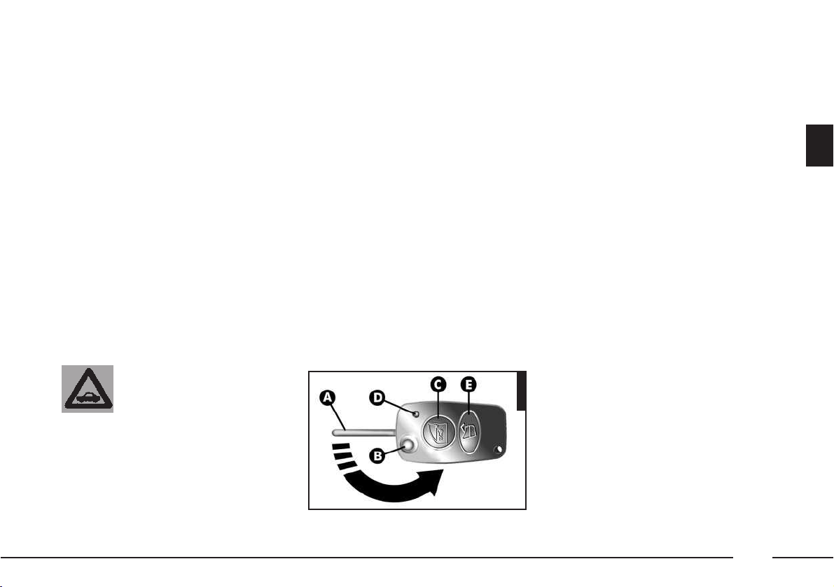
KEY WITH RADIO
FREQUENCY TRANSMITTER
WITH RE-CLOSABLE METALLIC
INSERT WITH POWERASSISTED OPENING
(fig. 6)
(optional for versions/markets where
applicable)
The key is fitted with:
– a metallic insert (A) that can be re-
closed in the key grip
– button (B) for power-assisted open-
ing of the metallic insert
– button (C) for remote opening/clos-
ing of the doors and turning the electronic
alarm on/off (where fitted)
– led (D) that signals the sending of
the code to the electronic alarm system
receiver
The CODE card (fig. 5), provided with
the key, bears the key codes (both mechanical and electronic code for emergency starting).
The code numbers on the CODE card
must be kept in a safe place, not in the
car.
The driver should always keep the electronic code given on the CODE card with
him in the event of having to carry out
emergency starting.
If the car changes ownership the new owner
must be given all the
keys and the CODE card.
fig. 6
1001PGSm
– button (E) for remote boot opening.
The metallic insert (A) of the key oper-
ates:
– the ignition
– front door locks
– boot lock
– glove box lock
– passenger’s Air bag deactivation
switch.
To move the metallic insert out of the
key grip, press button (B).
Page 18

18
To insert the metallic insert in the key
grip, keep button (B-fig. 6) pressed
and turn the insert on the direction of the
arrow until it clicks into place, then release the button (B).
To open/close the doors by remote con-
trol, press button (C). On cars fitted with
electronic alarm system, pressing button
(C) also turns the electronic alarm on/off
and the led (D) flashes while the transmitter sends the code to the receiver. This
rolling code changes at each transmission.
IMPORTANT If led (D) flashes only
once briefly when button (C) is pressed,
the battery need changing as described
below.
Opening the boot
The boot can be opened by remote
control from outside pressing button (E-
fig. 6), also when the electronic alarm
(where fitted) is on.
In this case the alarm disengages the
boot control sensor, the system (with the
exception of versions for certain markets)
sounds two beeps and the direction indicators light up for about three seconds.
When the boot is closed again the control function is restored, the system (with
the exception of versions for certain markets) sounds two beeps and the direction
indicators light up for about three seconds.
When button (B) is pres-
sed, take the utmost care
to prevent the metal insert from
causing injury or damage when it
comes out. Button (B) must only be
pressed when the key is away
from the body, in particular the
eyes, and from objects that could
be spoilt (e.g. clothes).
Never leave the key unattended to
prevent anyone, especially children, from holding it and pressing
button (B) inadvertently.
WARNING
Page 19
19
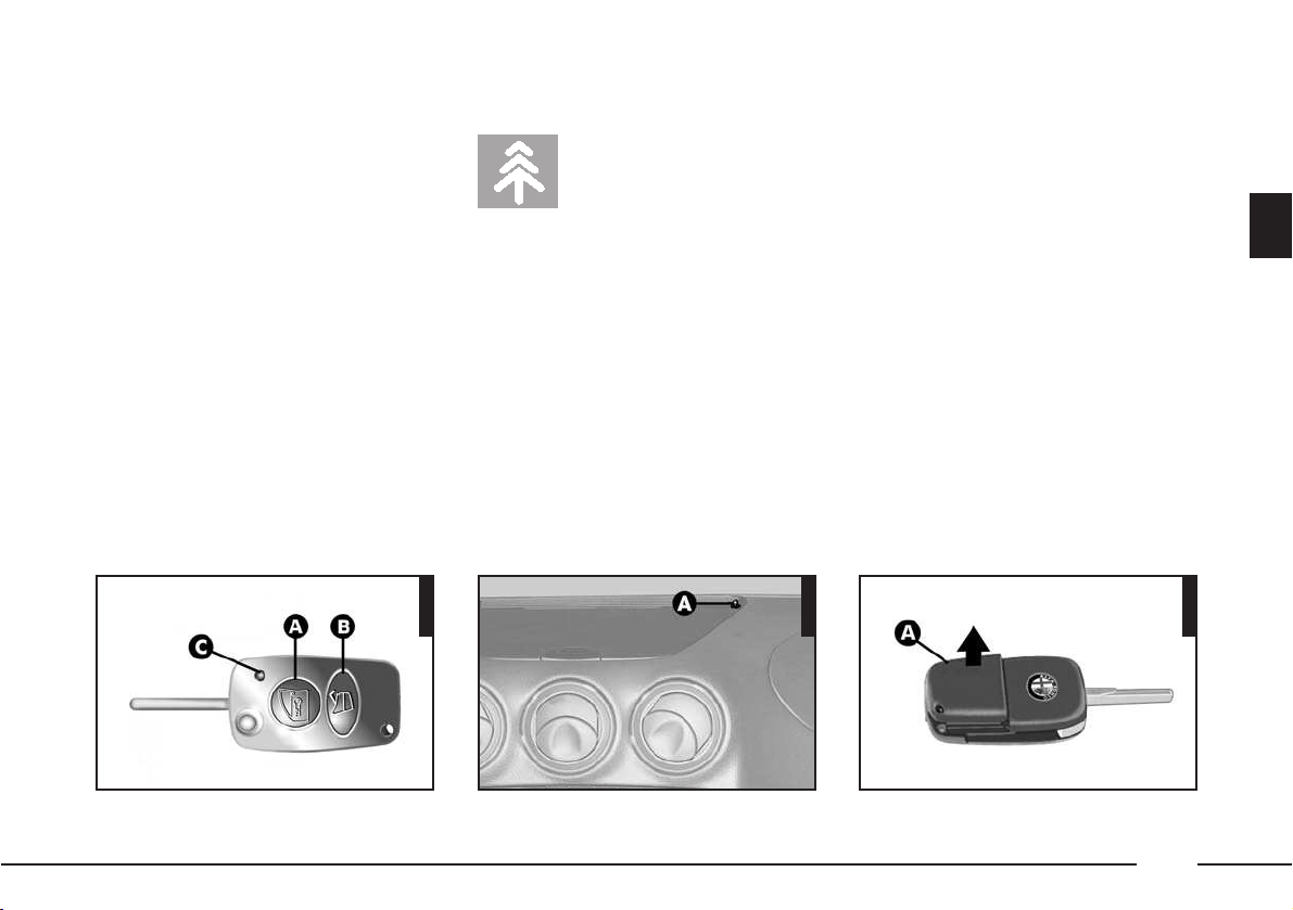
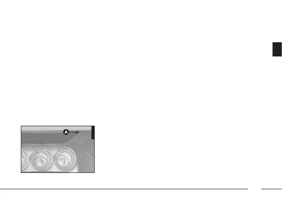
KEY BATTERY CHANGE
If pressing the remote control buttons
(A or B-fig. 7), the led (C-fig. 7)
gives only one brief flash and the alarm
system led (where fitted) (A-fig. 8) on
the dashboard stays on glowing steadily
for about 2 minutes (after turning off the
alarm and with the ignition switch off), it
is necessary to replace the battery with a
new one of the equivalent type to be
found c/o normal retailers.
To replace the battery, remove the plas-
tic lid (A-fig. 9), insert the new battery
according to the correct polarity and put
the lid back on.
For further information contact Autho-
rised Alfa Romeo Services.
OPERATION
Each time the ignition key is turned to
the STOP position, the Alfa Romeo
CODE system deactivates the functions of
the engine electronic control unit.
Each time the engine is started, turning
the key to the MAR position, the control
unit of the Alfa Romeo CODE system
sends a recognition code to the engine
control unit to deactivate the inhibition of
the functions.
The recognition code, which is crypted
and variable between over 4 billion combinations, is only sent if the system control unit has recognised the code sent to
it by the key, which contains an electronic
transmitter, through an aerial in the ignition switch.
Dead batteries constitute a hazard for the
environment and must
be disposed of in the special containers as specified by the relative laws.
fig. 7
1011PGSm
fig. 9
1034PGSm
fig. 8
305PGSm
Page 20
20
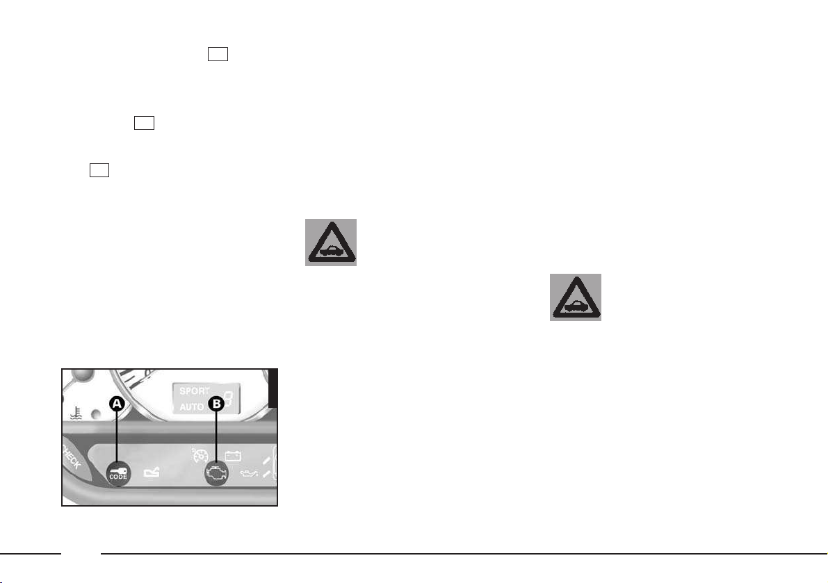
This condition is indicated by a brief
flash of the warning light (A-fig.
10) on the check panel.
If the code has not been recognised cor-
rectly, the Alfa Romeo CODE system
warning light (A-fig. 10) stays on
together with the EOBD/fuel supply-ignition system failure warning light (B-fig.
10) .
In this case, you are recommended to re-
turn the key to the STOP position and
than back to MAR; if the inhibition persists, try again possibly with the other key
provided with the car. If it is still impossible
to start the car, carry out the emergency
starting procedure described herein and
turn to an Alfa Romeo Authorized Service.
U
¢
¢
IMPORTANT Every electronic key has
its own code, which must be memorised
by the system control unit. To memorise
new keys, up to a maximum of seven,
apply solely to Alfa Romeo Authorized
Services taking with you all the keys in
your possession, the CODE card, a personal identity document and the car’s possession documents.
The codes of the keys
not provided during the
new memorising procedure are erased from the memory. This is to ensure that any lost
or stolen keys can no longer be
used to start the car.
IMPORTANT The Alfa Romeo CODE
warning light comes on when travelling
with the ignition key on MAR:
1) If the warning lamp lights up while
the car is moving, it means that the system is running a self-diagnosis (e.g. due to
a voltage drop). The first time you stop you can test the system as follows: switch
the engine off by turning the ignition key
to STOP; then turn the key back to
MAR: the warning lamp will light up and
should go out in the space of about one
second. If the warning lamp fails to go
out, leave the key at STOP for more than
30 seconds and repeat the procedure described previously. If the problem persists,
contact your Authorised Alfa Romeo Dealer.
2) If the warning lamp flashes it means
that the car is not protected by the immobiliser. Contact your Authorized Alfa
Romeo Code Dealer immediately and get
them to store the codes of all the keys in
the memory.
If after about 2 seconds
with the key in the
MAR position, the Alfa
Romeo CODE warning light turns
on again flashing at appr. half
second intervals, this means that
the code of the keys has not
been memorised, thus the car is
not protected by the Alfa Romeo
CODE system against attempted
theft. In this case, contact an Authorized Alfa Romeo Service to
have the key codes memorised.
fig. 10
A0D0091m
Page 21

21
IMPORTANT In the case of fast starting, turning the key directly from STOP
to AVV, the recognition code might not
be transmitted completely, preventing the
engine from starting: try again more
slowly.
IMPORTANT The system is protected
by two fuses housed in the main fusebox
(see “If a fuse or relay blows” in the
chapter “In an emergency”).
EMERGENCY STARTING
If it is not possible to deactivate the engine inhibitor with the ignition key, Alfa
Romeo Authorized Services can carry out
the emergency procedures using the code
of the CODE card, or, you may do this
yourself, following the procedure described below.
IMPORTANT You are advised to carefully read the entire procedure before carrying it out.
If a mistake is made during the emer-
gency procedure, the ignition key should
be turned to the STOP position and the
operations must be repeated from the start (point 1).
1) Read the 5-figure electronic code on
the CODE card.
2) Turn the ignition key to the MAR
position.
3) Fully depress the accelerator pedal
and keep it pressed. The EOBD/fuel supply-ignition system failure warning light
will come on for eight seconds approximately and will then go out; now release the accelerator pedal.
4) The warning light begins to
flash: after it has flashed for the same
number of times as the first digit on the
code of the card, press completely and
hold down the accelerator pedal until the
warning light comes on (for 4 seconds) and then goes out again; now release the accelerator pedal.
5) The warning light will begin to
flash: after it has flashed for the same
number of times as the second digit on
the code of the CODE card, press completely and hold down the accelerator
pedal.
U
U
U
U
6) Repeat this procedure in the same
way for the other digits on the CODE card
code.
7) After entering the last figure, keep
the accelerator pedal pressed. The warning light turns on (for four seconds)
and then goes off; now release the accelerator pedal.
8) A quick flash of the warning light
(for appr. 4 seconds) confirms that
the operation has taken place correctly.
9) Start the car turning the ignition key
from the MAR position to the AVV po-
sition without returning the key to the
STOP position.
Conversely, if the warning light
stays on, turn the ignition key to STOP
and repeat the procedure starting from
point 1).
IMPORTANT After emergency start-
ing it is advisable to turn to an Alfa
Romeo Authorized Service, because the
procedure described must be repeated
each time the engine is started.
U
U
U
Page 22
22
ELECTRONIC ALARM
(optional for versions/markets where
applicable)
DESCRIPTION
The system certified in accordance with
EC Directive 95/56 comprises: transmitter , receiver, control unit with siren and
volumetric sensors. The electronic alarm
is controlled by the receiver and it is
turned on and off through the remote
control incorporated in the key which
sends the crypted, variable code. The
electronic alarm monitors: unlawful opening of the doors, bonnet and boot
(perimetral protection), operation of the
ignition key, battery and emergency key
cable cutting, the presence of moving
bodies in the passenger compartment
(volumetric protection) and operates the
central door locking system. Is also
makes it possible to cut off volumetric
protection and/or the siren.
IMPORTANT The engine inhibitor
function is guaranteed by the Alfa Romeo
CODE system which is activated automatically when the ignition key is removed
from the lock.
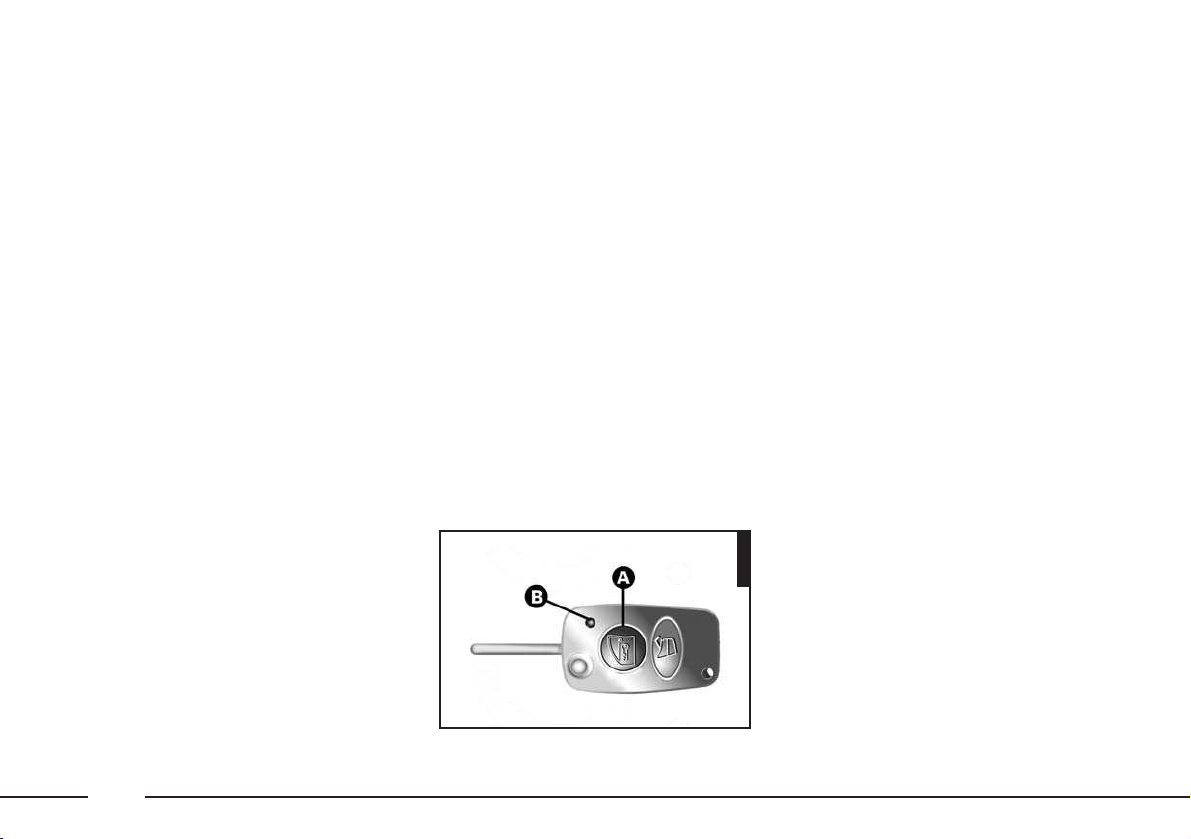
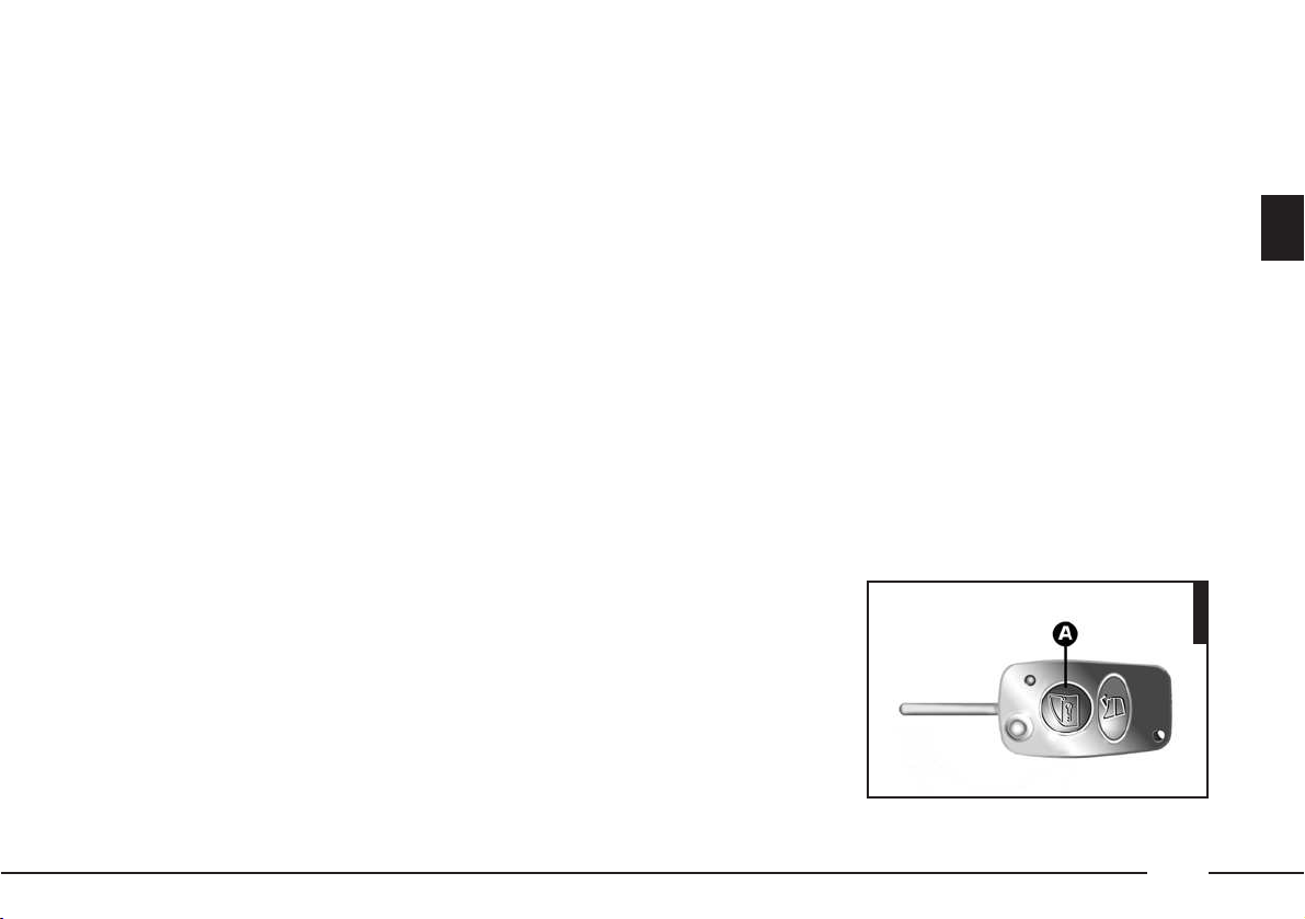
REMOTE CONTROL
(fig. 11)
The remote control is incorporated in the
key and it is fitted with a button (A) and
a led (B); the button activates the control, the led flashes while the transmitter
sends the code to the receiver. This code
(rolling code) changes at each transmission.
IMPORTANT If, when pressing the
push-button (A), the led (B) issues just a
short flash, replace the batteries as
shown in the previous paragraph.
Request for additional remote
controls
The receiver can recognise up to 5 re-
mote controls.
If during the life of the car a new remote control is needed for any reason
whatsoever, contact Alfa Romeo Authorized services directly, taking with you the
CODE card, a personal identity document
and the car’s possession documents.
fig. 11
1013PGSm
Page 23
23
ACTIVATING THE ALARM
When the doors and boot/bonnet lids
are closed and the ignition key is in the
STOP position (key removed), point the
remote control towards the car and press
the button on the ignition key.
With the exception of some markets the
system sounds a “BEEP”, the hazard
warning lights turn on for appr. three seconds and the door lock is engaged.
Engagement of the alarm is preceded
by a self-diagnosis characterised by a
change in the frequency at which the led
(A-fig. 12) flashes. If an anomaly is
detected the system gives off a further
“BEEP”.
Surveillance
When the system has been turned on,
the led (A-fig. 12) on the dashboard
will flash to indicate that the system is in
the surveillance mode.
The led (A) inside the car flashes
throughout the whole time the vehicle is
under surveillance.
IMPORTANT Operation of the elec-
tronic alarm is adapted at the origin to
the regulations of the different countries.
Self-diagnosis and monitoring of
doors and bonnet/boot
If, after the alarm has been activated, a
second acoustic signal is heard, check
that all the doors and bonnet/boot are
closed properly and engage the system
once again.
On the other hand, if a door or bonnet/boot lid is not correctly closed it will
not be controlled by the system.
If the control signal is repeated when
the doors and bonnet/boot are closed
properly this means that the self-diagnosis function has detected a system operating fault, in which case it is necessary
contact Alfa Romeo Authorized Services.
DEACTIVATING THE ALARM
To deactivate the alarm press the button
on the remote control. The system performs the following (with the exception
of some markets):
– the direction indicators turn on twice
briefly
– two beeps are sounded briefly by the
siren
– the doors are released.
IMPORTANT If the led in the car stays on when the system has been deactivated, (maximum of 2 minutes or until
the ignition key is moved to MAR) the
following should be borne in mind:
– if the led stays on permanently, it
means that the remote control batteries
are flat and need replacing;
– if the led continues to flash, but at
different intervals than normal, it means
that attempts to steal the car have been
made, counting the number of flashes it
is also possible to identify the type of attempt:
1 flash: right front door
2 flashes: left front door
fig. 12
305PGSm
Page 24

24
3 flashes: right rear door
4 flashes: left rear door
5 flashes: volumetric sensors
6 flashes: bonnet
7 flashes: boot
8 flashes: tampering with car starting
cables
9 flashes: tampering with battery cables
or cutting emergency key cables
10 flashes: at least three causes of alarm.
WHEN THE ALARM IS
TRIGGERED
When the alarm is engaged it will sound
when:
– One of the doors, the bonnet or the
boot is opened.
– The battery is disconnected or the
electric cables are cut, or the emergency
key cables are cut.
– Intrusion into the passenger compartment, e.g. window being broken (volumetric protection).
– Attempt to start the engine (key at
MAR).
Depending on the markets, the triggering of the alarm will activate the siren
and the hazard warning lights (for about
26 seconds). The methods of operation
and the number of cycles may vary depending on the versions/markets. However a maximum number of cycles is foreseen. Once the alarm cycle has come to
an end the system will return to its normal monitoring state.
SWITCHING OFF THE ALARM
To switch off the alarm, press the remote control button on the key. If the
alarm does not turn off due to a flat remote control battery or system fault,
open the door after unlocking with the
lock key, then place the key in the ignition switch and turn it to MAR.
To turn on the alarm again, turn the key
to STOP and remove it, then press the
remote control button after leaving the
car and shutting the doors. If the alarm
does not turn on and the led on the remote control gives only one brief flash
while the led on the dashboard stays on
glowing steadily for about 2 minutes, the
key battery should be replaced by a new
one of the equivalent type on sale c/o
normal retailers. To change the battery
follow the instructions given at paragraph
“Key battery change” on previous pages.
If it is not possible to switch on the
alarm with a new remote control battery,
contact Alfa Romeo Authorised Services
to have the system checked.
Page 25
25
IMPORTANT If the car is to remain i-
nactive for a prolonged length of time
(over three weeks) and security conditions permitting, it is advisable to operate
central locking turning the key in the door
lock to avoid engaging the alarm and
draining the battery.
VOLUMETRIC PROTECTION
To guarantee correct operation, all the
windows and the sunroof (optional for
versions/markets where applicable)
should be closed. This function can be excluded (for example when leaving animals on-board the vehicle) by performing
the following operations in quick succession: when the ignition key is at the
MAR position, move the key to the
STOP position and then return the key
to the MAR and then once again to the
STOP position. Remove the ignition key.
The led in the vehicle will come on for
about 2 seconds to confirm that the function has been excluded.
To restore volumetric protection move
the ignition key to the MAR position
and hold it in this position for more than
30 seconds.
If requiring to activate an electric control
operated by the ignition key at MAR
(e.g. electric windows) with the volumetric protection deactivated, turn the ignition key to MAR, operate the control
and return the key to STOP within a
maximum time of 30 seconds. This way
volumetric protection is not restored.
CUTTING OUT OPERATION OF
THE SIREN
(optional for versions/markets where
applicable)
When requiring to dispense with the
siren acoustic signalling in the alarm condition, simply keep the remote control
button (A-fig. 13) pressed for 4 seconds when engaging the system.
This condition is shown by a series of 5
beeps in quick succession after the normal acoustic/visual signals when the system is operated.
The next time the system is activated,
normal operation of the siren is restored
automatically.
fig. 13
1014PGSm
Page 26
26
MINISTERIAL
HOMOLOGATIONS
In keeping with the laws in force in
each country on the subject of radio frequency, we point out that:
– the separate homologation numbers
for each market are given on the last
pages of this handbook before the alphabetical index (for some countries also homologation document);
– for markets in which the transmitter
needs to be marked with the homologation number, this has been stated on the
component.
(Depending on the versions/markets,
the code may also be marked on the
transmitter and/or on the receiver).
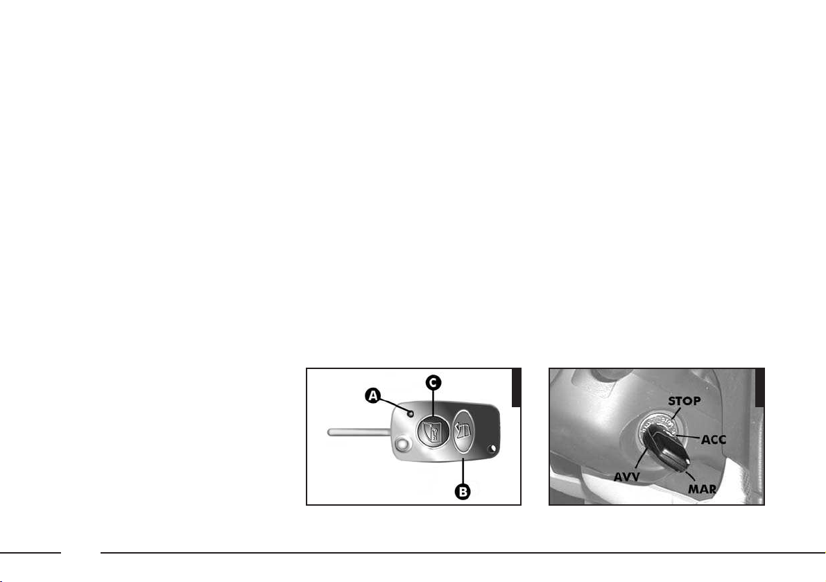
REMOTE CONTROL
DOOR LOCKING
SYSTEM
The system comprises a receiver and a
transmitter (remote control) incorporated
in the key (B-fig. 14). To lock/unlock
the locks, point the transmitter towards
the car, press and release the button
(C). If, when pressing the remote control
push-button (C), the led (A) issues just
a short flash, replace the batteries as described in the “The Alfa Romeo CODE
system” paragraph.
IMPORTANT Should it be necessary
to programme additional remote controls,
contact Alfa Romeo Authorized Services.
IGNITION DEVICE
THE SWITCH
(fig. 15)
The switch has four positions:
– STOP: engine switched off, key can
be removed, engine lock engaged, steering lock engaged, all services excluded apart from those powered directly (e.g.
hazard warning light I.C.S. system (except climate control).
– ACC: position for using the cigar
lighter and of the I.C.S. system (except
climate control).
– MAR: drive position. The engine
lock is deactivated and all electrical devices are powered.
fig. 14
1015PGSm
fig. 15
1004PGSm
Page 27
27
IMPORTANT Never leave the key in
this position when the engine is stationary.
– AVV: starting the engine.
IMPORTANT If the engine does not
start return the ignition key to the STOP
position and repeat the sequence.
The ignition block is fitted with a safety
device preventing it from being moved to
the AVV position when the engine is al-
ready running.
If the ignition device is
tampered with (for ex-
ample during an attempted break-in) have it checked
over by Alfa Romeo Authorized
Services, before travelling again.
STEERING LOCK
Engaging lock:
– move the key to the STOP position
and remove the key lightly turning the
steering wheel to facilitate the locking action.
Releasing the lock:
– turn the key to the MAR position
and gently rock the steering wheel in
both directions.
When leaving the vehicle
always remove the key
from the ignition to prevent any
passenger in the car from inadvertently activating the controls.
Never leave children unattended in
a car. Remember to engage the
handbrake and if the vehicle is facing uphill, first gear and if the vehicle is facing downhill, reverse.
WARNING
Never remove the key
with the car on the
move. The steering wheel would
lock automatically the first time
the steering wheel is turned. This
also occurs if the car is towed.
WARNING
It is absolutely forbidden
to carry out whatever after-market operation involving
steering system or steering column
modifications (e.g.: installation of
anti-theft Device) that could badly
affect performance and safety,
cause the lapse of warranty and
also result in non-compliance of the
car with homologation requirements.
WARNING
Page 28
28
DOORS
AUTOMATIC DOOR LOCKING
The automatic door locking function activates automatically when the car speed
exceeds 20 km/h.
This function can be deactivated and reactivated by the following procedure, to
be carried out with the car at a standstill,
key at STOP and doors closed:
- turn the key to MAR
- keep button (A-fig. 20) on the cen-
tral console pressed until completing a full
centralised door locking cycle (opening
and closing or vice versa).
IMPORTANT Depending on the ver-
sions/markets the lock for the key may
only be present on the driver’s door.
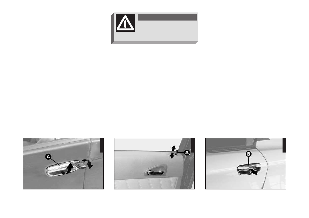
– To close the door, turn the key in the
opposite direction.
Rear doors
– To open the door, only with the inner
knob (A-fig. 17) raised, pull the opening handle (B-fig. 18).
– To close the door in safety, press the
button (A-fig. 17) also with the door
open, then close it.
OPENING/CLOSING FROM
OUTSIDE
Front doors
– To open the door, turn the key (clockwise for the driver’s door, counter-clockwise for the passenger’s door) and then
remove the key and pull the handle (A-
fig. 16).
Before opening a door
ensure that this can be
done safely.
WARNING
315PGS
1005PGS
fig. 16 fig. 18
318PGS
fig. 17
Page 29
29
– To open the door pull handle (B).
– To close the door press the knob (A)
even when the door is open, and then
close it.
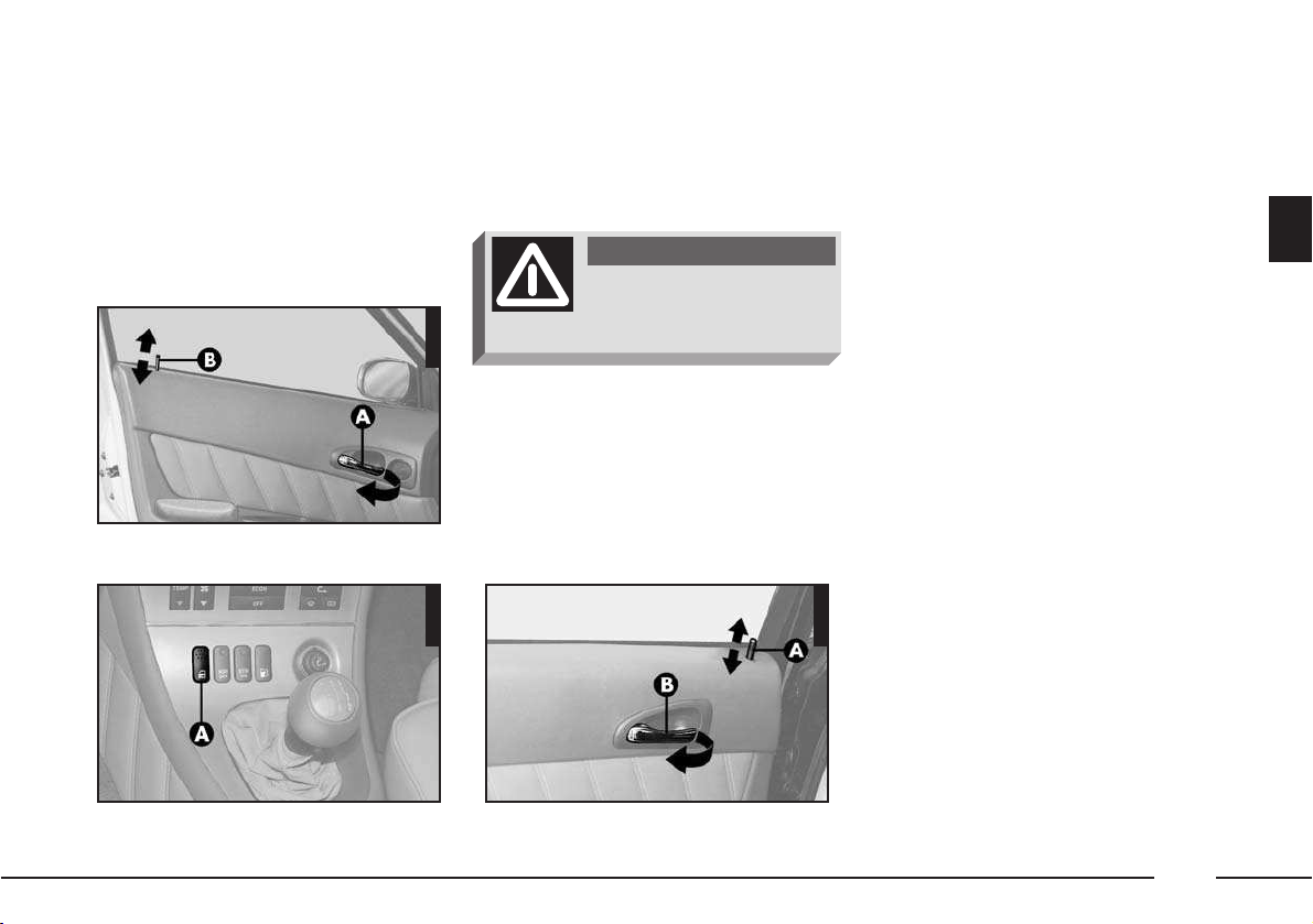
OPENING/CLOSING
FROM INSIDE
Front doors
– To open the door pull the handle
(A-fig. 19) regardless of the position
of knob (B-fig. 19).
– Pull the door to close; then, to pre-
vent the door from being opened from
CENTRALIZED LOCKING
This permits centralized locking of all
doors, both front and rear.
To operate the centralized locking device the doors must be perfectly closed
otherwise the system will not work.
IMPORTANT If one of the doors is
not closed properly the led on the relative
“door open” display will come on.
For versions/markets where applicable,
central locking depends on the complete
closing of all the doors and of the boot.
– From outside: when the doors are
closed, insert and turn the key in the lock
of one of the two front doors.
IMPORTANT Depending on the versions/markets the lock for the key may
only be present on the driver’s door.
outside, press the button (A-fig. 20)
on the centre console or the knob (B-
fig. 19).
Rear doors (fig. 21)
The rear doors can only
be opened if the child
safety lock has been released.
WARNING
fig. 19
fig. 20
P4C00057313PGSmA0D0006m
fig. 21
314PGSm
Page 30
30
– From inside: with the doors closed,
press the button (A-fig. 20) on the
centre console or one of the knobs
(B-fig. 19) on the front doors to engage (lock) central locking.
By pressing the knob (A-fig. 21) on
one of the rear doors only that particular
door will be locked.
To unlock central locking press the button
again (A-fig. 20).
IMPORTANT For the front doors it is
not possible to keep the knob (B-
fig. 19) down if the door has not been
shut properly.
IMPORTANT If the power supply is
interrupted (burnt fuse, battery disconnected etc.) each door can be opened
manually from both inside and outside
the vehicle.
IMPORTANT The centralized locking
system can be deactivated, thus unlocking all doors, by lifting the door opening
lever on one of the two front doors.
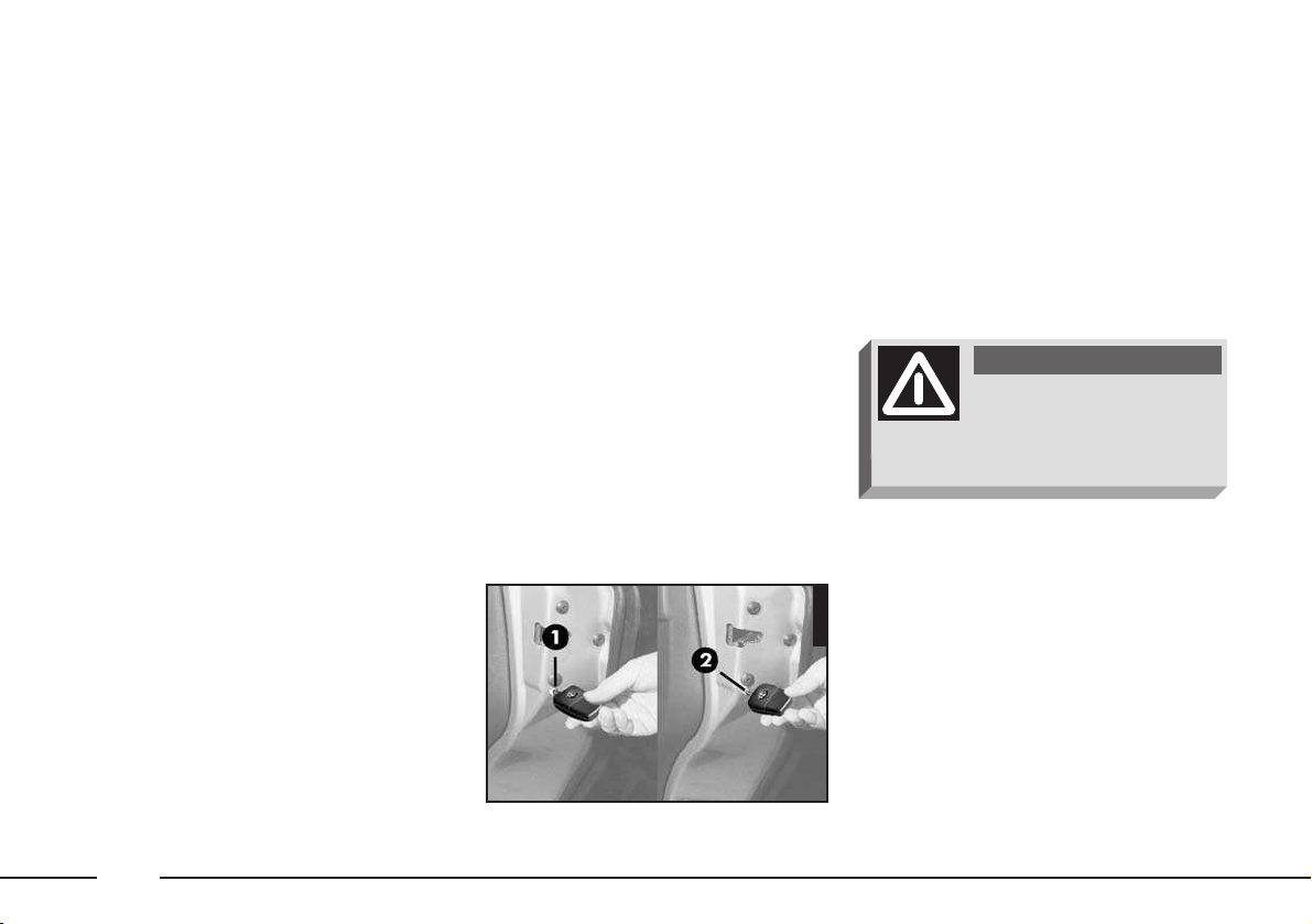
CHILD SAFETY LOCK
(fig. 22)
The rear doors are equipped with a special device which prevents the door being
opened from inside.
The device can be engaged when the
door is open by acting on the relative control using the ignition key.
Position 1 = Device inactive
Position 2 = Device engaged.
This device should be used when children are in the back seat to prevent them
from opening the door whilst the car is
moving.
IMPORTANT Do not overlook child
safety; the following recommendations
should be heeded:
– Engage the child safety device.
– Do not leave a child alone in the vehi-
cle.
– Follow the current laws regarding
child restraint and safety systems.
After activating the safety
device check that it is
working correctly by pulling on the
inner lever used to open the door.
WARNING
fig. 22
1006PGSm
Page 31

31
SEATS
FRONT SEATS
Manual adjustment controls
Moving the seat backwards or
forwards
Lift lever (A-fig. 23) and push the
seat backwards or forwards.
IMPORTANT Once you have let go
of the lever, check that the seat is firmly
locked in the runners by trying to move it
back and forth. If the seat is not locked
properly, in the case of collision it might
move unexpectedly with clearly dangerous consequences.
Adjusting the height of the
driver’s seat
To raise the seat, pull the lever (B-
fig. 23) taking it upwards, then contin-
ue operating the lever (up and down) until reaching the required height. To lower
the seat, push the lever (B) downwards,
then operate the lever (up and down) until reaching the height required.
IMPORTANT Adjustment must only
be carried out when seated in the driver’s
seat.
Seat inclination power adjustment
The adjustment is performed by apply-
ing pressure on the front or back part of
the two-position switch (C-fig. 23).
Seat warming (fig. 24)
(optional for versions/markets where
applicable)
The seat warming pad can be switched
on and off using switch (A) on the outer
side of the seat.
When the warming pad is on, the led
on the switch turns on.
Adjustments may be
made solely with the car
stationary.
WARNING
fig. 23
674PGSm
fig. 24
672PGSm
Page 32

32
Controls for seats with electric
adjstment
(on request for versions/
markets where applicable)
The position of the seats is adjusted
electrically with the controls (A-fig. 25-
26) and (B-fig. 25-27):
A - Multifunction control:
1 - raising the front of the seat
2 - raising the rear of the seat
3 - vertical movement of the seat
4 - longitudinal movement of the seat.
B - Multifunction control:
5 - seat back rake adjustment
6 - lumbar adjustment of the seat.
C - Seat heating.
Lumbar adjustment of the seat is carried
out raising or lowering the control (B-
fig. 25-27), until finding the most
comfortable position.
Seat heating (fig. 28)
Seat heating is turned on and off using
the switch (C) on the outer side of the
seat.
When seat warming is on the led on the
switch lights up.
Memorising the driver’s seat
positions (fig. 29)
The system makes it possible to memorise and call up three different positions
of the driver’s seat.
To memorise a seat position, proceed as
follows:
1) Adjust the position of the driver’s
seat with the controls described in the
previous paragraph.
2) Simultaneously press (for about 1
second) the button (MEM-fig. 29)
and one of the buttons (1), (2), or (3),
each corresponding to a position that can
be memorised.
3) Proceed in the same way to memorise the other two positions of the seat.
fig. 26fig. 25
319PGSm
604PGSm
fig. 27
603PGSm
Page 33

33
Adjusting the headrests (fig. 30)
Front headrests are adjustable in height
and rake: to adjust the height, move the
headrest up or down, then release it and
make sure that it is locked on one of the
positions provided. To adjust the rake,
turn the headrest forwards to the required
position.
IMPORTANT The shape of the headrest may vary depending on the version
and/or market. The example shown is
used only to demonstrate the methods by
which it can be adjusted.
When memorising a new position of the
seat the previous one memorised with
the same button is cleared automatically.
Keeping the corresponding button (1),
(2), or (3) pressed the positions memorised can be called even if the ignition
key is in the STOP position or removed.
IMPORTANT Memorising the positions of the seat does not include turning
on the heating.
Remember that the head
restraints must be positioned so that they are supporting
the back of the head and not the
neck. They will only be able to provide effective protection in the
event of a collision if they are in
this position.
WARNING
fig. 28
373PGSm
fig. 30
A0D0064m
fig. 29
660PGSm
Page 34

34
Centre armrest (fig. 32-33)
To raise/lower the armrest, lower it as il-
lustrated. To lower/raise the armrest keep
the lock button pressed (A-fig. 32).
To use the armrest, lower it as illustrated.
There is a compartment inside the arm-
rest: to open, lift the cover (fig. 33).
Rear pockets (fig. 31)
The front seats are provided with a
pocket in the rear of the seat back.
568PGSm
fig. 33
561PGSm
fig. 32
337PGSm
fig. 31
Page 35

35
REAR SEAT
Centre armrest
To use the centre armrest, lower it as il-
lustrated (fig. 34).
Ski compartment
The compartment may be used for carrying long loads. To gain access to this
compartment, lower the armrest and then
lower the lid (A-fig. 35) onto the arm-
rest.
Pull the handle (A-fig. 36) to open
the door from the luggage compartment.
Headrest (fig. 37)
The car is fitted with two headrests for
the side rear seats.
The rear headrests are fixed and inte-
grated in the seat back.
371PGSm
fig. 37
366PGSm
fig. 35
365PGSm
fig. 34
671PGSm
fig. 36
Page 36

36
STEERING WHEEL
ADJUSTMENT
(fig. 38)
The steering wheel position is adjustable
and may be moved nearer to or further
away from the driver and also raised or
lowered.
To do this, it is necessary to release
lever (A) pulling it towards the steering
wheel. After setting the steering wheel in
the most appropriate position, lock it
pushing the lever forwards fully home.
ADJUSTING THE
REAR-VIEW MIRRORS
INTERNAL REAR-VIEW
MIRROR
(fig. 39-40)
The mirror, fitted with a safety device
which releases it in the event of a violent
impact can be moved to two positions operating lever (A-fig. 39): normal or anti-glare.
IMPORTANT The configuration of the
mirror may vary depending on the vehicle
trim level. The figure here is demonstrative only to show how it is adjusted.
For some versions/markets the mirror
(fig. 40) automatically sets to the day
or night position.
The steering wheel position must only be ad-
justed with the vehicle stationary.
WARNING
fig. 39fig. 38
317PGS
310PGS
fig. 40
675PGS
It is absolutely forbidden
to carry out whatever after-market operation involving
steering system or steering column
modifications (e.g.: installation of
anti-theft Device) that could badly
affect performance and safety,
cause the lapse of warranty and
also result in non-compliance of the
car with homologation requirements.
WARNING
Page 37

37
Folding (fig. 41-42)
– If necessary (for example when the
size of the mirror causes difficulty in narrow paces) the door mirror can be folded
in towards the vehicle from position (A-
fig. 42) to position (B).
For some versions/markets the mirrors
can be folded electrically using a button
(C-fig. 41).
Defrosting/demisting (fig. 43)
The electric mirrors can be fitted with
heating coils which are operated together
with rearscreen heating pressing button
(A) which prevent the mirrors from frosting and/or misting.
This function is timed and is deactivated
after a few minutes.
DOOR MIRRORS
Electrically adjustable (fig. 41)
– Select the mirror to be adjusted using
switch (A) (right or left).
– Press button (B) to one of the four
directions and adjust the mirror selected
previously.
– Position the switch (A) in the inter-
mediate locking position.
The mirror can only be adjusted electri-
cally when the ignition key is in the
MAR position.
Curved door mirrors (for
versions/markets where
applicable) slightly alter the perception of distance.
WARNING
When travelling the door
mirrors must always be
in position (A).
WARNING
fig. 41
570PGSm
fig. 42 fig. 43
P4C00057A0D0007m
A0D0010m
Page 38

38
POWER WINDOWS
FRONT
Driver’s side (fig. 44)
The driver’s door armrest contains the
buttons which, with the ignition key at
MAR, operate the following windows:
A - left front window
B - right front window.
Press the button to lower the window.
Pull the button to raise it.
IMPORTANT The driver’s power win-
dow is fitted with a “continuous automatic operation” device for both lowering
and raising the window. A brief press on
the upper or lower part of the button will
cause the window to move and continue
its stroke automatically: the window
stops in the position required by pressing
either the upper or lower part of the button again.
With the ignition key at STOP or re-
moved, the power windows remain activated for about 2 minutes or until a front
door is opened.
Passenger’s side (fig. 45)
Button (A) is used to operate the pas-
senger’s window.
The passenger’s window is fitted with a
device for “continuous automatic operation” only for lowering it.
The device works as describes for the
driver’s window.
fig. 45fig. 44
A0D0008m
531PGSm
Page 39

39
REAR
The rear windows are operated by the
split controls on the driver’s door and
those on each rear door.
With the ignition key on MAR, press
the button to lower the window, pull the
button or raise it.
Controls on driver’s door (fig. 46)
The following controls are located on
the inner driver’s door panel plate:
C - left rear window
D - right rear window
E - rear door window controls inhibitor
(with the inhibitor activated the led on
the button is lit).
Do not hold the button
down when the window
is fully open or fully
closed.
Controls on rear doors (fig. 47)
Each rear door panel plate contains a
button (A) for operating the corresponding window.
Incorrect use of the
power windows can be
dangerous. Before and during operation of them always make sure
that the passengers are not exposed to the risk of harm caused
either directly by the windows in
motion or by personal objects
drawn or knocked by them. When
leaving the vehicle always remove
the ignition key to prevent passengers (especially children) from
being injured by the power windows inadvertently operated.
WARNING
fig. 46
A0D0009m
fig. 47
328PGSm
Page 40

40
SEAT BELTS
USING THE SEAT BELTS
The belt should be worn keeping the
chest straight and rested against the seat
back.
Take hold the tongue (A-fig. 48) and
insert it into the buckle (B), until hearing
the locking click.
At removal, if it jams, let it rewind for a
short stretch, then pull it out again without jerking.
To unfasten the seat belts, press button
(C).
Guide the seat belt with your hand
while it is rewinding, to prevent it from
twisting.
Through the reel, the belt automatically
adapts to the body of the passenger
wearing it, allowing freedom of movement.
When the car is parked on a steep slope
the reel mechanism may block; this is
normal. The reel mechanism prevents the
webbing coming out when it is jerked or
if the car brakes sharply, in a collision or
when cornering at high speed.
The rear seat is fitted with inertial seat
belts with three anchor points with reel for
the side seats and an abdominal belt with
two anchor points for the centre (A-fig.
49) seat. For versions/markets where applicable, the centre seat can be fitted with
inertial seat belt with three anchor points
and reel like side seats (fig. 50).
Never press button (C)
when travelling.
WARNING
571PGSm
fig. 48 fig. 49
A0D0130m
A0D0131m
fig. 49/A
To offer the highest level
of protection, the rear seat
belts should be fastened as shown
in fig. 49 and fig. 50.
WARNING
Page 41

41
Remember that in the
event of a violent collision, back seat passengers not
wearing seat belts also represent
a serious danger for the front seat
passengers.
WARNING
fig. 50
A0D0128m
fig. 50/A
A0D0129m
REAR CENTRAL ABDOMINAL
BELT (
fig. 51
) (
where provided
)
Fasten the belt by inserting the tab (A)
into the clip (B) until a click is heard.
To adjust the belt, run the tape in the
buckle (D) pulling the end (E) to tighten
and part (F) to loosen.
Press button (C) to release the belt.
IMPORTANT The belt is adjusted cor-
rectly when it adheres to the pelvis.
When the rear seats are not occupied,
the appropriate spaces between the backrest and cushion should be used to stow
the seat belt clips neatly.
FRONT SEAT BELT HEIGHT
ADJUSTMENT
Make the height adjustment when the car is sta-
tionary.
WARNING
fig. 51 fig. 52
320PGSm
3139CAm
Always adjust the height of the seat belt
to fit the person wearing it.
Page 42

42
PRETENSIONERS
To increase the efficiency of the front
seat belts, the Alfa 166 is fitted with
pretensioners.
These devices “feel”, through a sensor,
that a violent crash is in progress and
rewind the seat belts a few centimetres.
In this way they ensure that the seat belt
adheres perfectly to the wearer before
the restraining action begins.
The seat belt locks to indicate that the
device has intervened; the seat belt cannot be drawn back up even when guiding
it manually.
IMPORTANT To obtain the highest
degree of protection from the action of
the pretensioning device, wear the seat
belt keeping it firmly close to the chest
and pelvis.
Front seat pretensioners activate only if
front seat belts are properly fitted into
buckles.
A small amount of smoke may be produced. This smoke is in no way toxic and
presents no fire hazard.
The pretensioner does not require any
maintenance or greasing. Anything that
modifies its original conditions invalidates
its efficiency. If due to unusual natural
events (floods, sea storm, etc.) the device has been affected by water and
mud, it must necessarily be replaced.
After adjustment, always
check that the slider is
anchored in one of the positions
provided. To do this, with the button (A-fig. 52) released, exert a
further pressure to allow the anchor device to catch if release did
not take place at one of the preset
positions.
WARNING
The pretensioner can only
be used once. After a collision that has triggered it, have it
replaced at an Alfa Romeo Authorized Services. The validity of the
device is 10 years starting from
the date of production, the pretensioners should be replaced at an
Alfa Romeo Authorized Services as
this date approaches.
WARNING
This precaution could greatly reduce the
risk of injury in case of collision.
Correct adjustment is obtained when the
belt passes half way between the end of
the shoulder and the neck.
4 different adjustments in height are
provided.
To adjust the attachment raise or lower
the grip (A-fig. 52) and ring (B-
fig. 52) to one of the set positions.
Page 43

43
Operations which lead to
knocks, vibrations or lo-
calised heating (over
100°C for a maximum of 6 hours)
in the area around the pretensioners may cause damage or trigger
them. These devices are not affected by vibrations caused by irregularities of the road surface or
low obstacles such as kerbs, etc.
Contact a Alfa Romeo Authorized
Services for any assistance.
GENERAL INSTRUCTIONS FOR
USING THE SEAT BELTS
The driver must comply with (and have
the vehicle occupants follow) all the local
legal regulations concerning the use of
seat belts.
Always fasten the seat belts before starting.
For maximum safety,
keep the back of your
seat upright, lean back into it and
make sure the seat belt fits closely
across your chest and hips.
Make sure that the seat belts of
the front and rear passengers are
fastened at all times! You increase
the risk of serious injury or death
in a collision if you travel with the
belts unfastened.
WARNING
The belt should not be
twisted, make sure that it
is taut and adheres to the passenger’s body. The upper part should
pass over the shoulder and cross
the chest diagonally. The lower part
should adhere to the pelvis and to
the abdomen of the passenger, (fig.
53). Do not use any objects (pegs,
stoppers, etc.) to keep the belts
away from the body.
WARNING
Under no circumstances
should the components of
the seat belts and pretensioner be
tampered with or removed. Any
operation should be carried out by
qualified and authorised personnel.
Always contact Alfa Romeo Authorized Services. If the belt has
been subjected to heavy stress, for
example after an accident, it
should be changed completely together with the anchors, anchor
fastening screws and the pretensioners. In fact, even if the belt has
no visible defects, it could have
lost its resilience.
WARNING
593PGSm
fig. 53
Page 44

44
Seat belts are also to be worn by expectant mothers: the risk of injury in the case
of accident is greatly reduced for them
and the unborn child if they are wearing
a seat belt.
Of course they must position the lower
part of the belt very low down so that it
passes under the abdomen (fig. 55).
HOW TO KEEP THE SEAT BELTS
ALWAYS IN EFFICIENT
CONDITIONS
1) Always use the belt with the tape
taut and never twisted; make sure that it
is free to run without impediments.
2) After a serious accident, replace the
belt being worn at that time, even if it
does not appear damaged. Always replace the seat belts if pretensioners have
been activated.
3) To clean the belts, wash by hand
with neutral soap, rinse and leave to dry
in the shade. Never use strong detergents, bleach or dyes or other chemical
substance that might weaken the fibres.
4) Prevent the reels from getting wet:
their correct operation is only guaranteed
if water does not get inside.
5) Replace the seat belt when showing
significant wear or cut signs.
Never travel with a child
sitting on the passenger’s lap with a single belt to protect them both (fig. 54). Do not
fasten other objects to the body.
WARNING
595PGSm
fig. 54
594PGSm
fig. 55
Page 45

45
CARRYING CHILDREN SAFELY
For optimal protection in the event of a
crash, all passengers must be seated and
wearing adequate restraint systems.
This is even more warning for children.
According to 2003/20/EC Directive,
this prescription is compulsory for all European Community countries.
Compared with adults, their head is proportionally larger and heavier than the
rest of the body, while the muscles and
bone structure are not completely developed. Therefore, correct restraint systems
are necessary, other then adult seat belts.
fig. 56
003STZm
SERIOUS DANGER: Never place cradle child’s seats on the
front passenger seat of cars fitted with passenger air bag
since the air bag activation could cause serious injuries, even mortal. You
are advised to carry children always on the rear seat, as this is the most
protected position in the case of a crash. In any case, children's seats must
absolutely not be fitted on the front seat of car’s with passenger’s air bag,
which during inflation could cause serious injury, even mortal, regardless
of the seriousness of the crash that triggered it.
Children may be placed on the front seat of cars fitted with passenger’s
air bag deactivation. In this case, it is absolutely necessary to check the
warning light
F on the cluster to make sure that deactivation has ac-
tually taken place (see paragraph “Front and side air bags” at item “Passenger’s front air bag”). The front passenger seat shall be adjusted in the
most backward position to prevent any contact between child’s seat and
dashboard.
WARNING
Page 46

46
The results of research on the best child
restraint systems are contained in the European Standard ECE-R44. This Standard
enforces the use of restraint systems classified in five groups:
Group 0 0-10 kg in weight
Group 0+ 0-13 kg in weight
Group 1 9-18 kg in weight
Group 2 15-25 kg in weight
Group 3 22-36 kg in weight
As it may be noted, the groups overlap
partly and in fact, in commerce it is possible to find devices that cover more than
one weight group (fig. 56).
All restraint devices must bear the certification data, together with the control
brand, on a solidly fixed label which must
absolutely never be removed. Over
481.50 m in height, from the point of
view of restraint systems, children are
considered as adults and wear the seat
belts normally.
Lineaccessori Alfa Romeo offers seats
for each weight group, which are the recommended choice, as they have been designed and experimented specifically for
Alfa Romeo cars.
GROUP 0 and 0+
Babies up to 13 kg must be carried facing backwards on a cradle seat, which,
supporting the head, does not induce
stress on the neck in the event of sharp
deceleration. The cradle is restrained by
the car seat belts, as shown in (fig. 57)
and in turn it must restrain the child with
its own belts.
GROUP 1
Starting from 9 kg to 18 kg in weight,
children may be carried facing forwards,
with seats fitted with front cushion
(fig. 58), through which the car seat
belt restrains both child and seat.
004STZm
fig. 57 fig. 58
005STZm
Illustration is indicative
for assembly only. Assemble the seat according to the
compulsory instructions provided
with it. Child’s seat shall not be
assembled on the rear central seat.
WARNING
Page 47

47
GROUP 2
Starting from 15 kg to 25 kg in weight,
children may be restrained directly by the
car belts. The only function of the seat is to
position the child correctly in relation to the
belts, so that the diagonal part adheres to
the chest and not to the neck and that the
horizontal part clings to the child’s pelvis
and not the abdomen (fig. 59).
GROUP 3
For children from 22 kg up to 36 kg the
size of the child’s chest no longer requires
a support to space the child’s back from
the seat back.
(Fig. 60) shows proper child seat positioning on the rear seat.
Children taller than 1.50 m can wear
seat belts like adults.
006STZm
007STZm
fig. 59 fig. 60
Seats exist which are
suitable for covering
weight groups 0 and 1 with a rear
connection to the vehicle belts and
their own belts to restrain the
child. Due to their size, they can be
dangerous if installed incorrectly
fastened to the car belts with a
cushion. Carefully follow the instructions for installation provided
with the seat.
WARNING
Illustration is indicative
for assembly only. Assemble the seat according to the
compulsory instructions provided
with it. Child’s seat shall not be
assembled on the rear central seat.
WARNING
Illustration is indicative
for assembly only. Assemble the seat according to the
compulsory instructions provided
with it. Child’s seat shall not be
assembled on the rear central seat.
WARNING
Page 48

48
Below is a summary of the
rules of safety to be followed
for carrying children:
1) The recommended position for in-
stalling children’s seat is on the rear seat,
as it is the most protected in the case of
a crash.
2) If the passenger’s air bag is deacti-
vated always check the warning light
F on the cluster to make sure that it
has actually been deactivated.
3) Attain to the instructions for fasten-
ing the specific child restraint system
which you are using. These instructions
must be provided by the manufacturer.
Keep the child restraint system installation instructions with the car documents
and this Handbook. Never use a child restraint system without installation instructions.
4) Always check the seat belt is well
fastened by pulling the webbing.
5) Only one child is to be strapped to
each retaining system.
6) Always check the seat belts do not
fit around the child’s throat.
7) While travelling, do not let the child
sit incorrectly or release the belts.
8) Passengers should never carry chil-
dren on their laps. No-one, however
strong they are, can hold a child in the
event of a crash.
9) In case of an accident, replace the
seat with a new one.
In cars fitted with pas-
senger air bag never
place child’s restraint systems on
the front seat since children shall
never be seated on the front passenger seat.
WARNING
Illustration is indicative
for assembly only. Assemble the seat according to the
compulsory instructions provided
with it. Child’s seat shall not be
assembled on the rear central seat.
WARNING
Page 49

49
PASSENGER SEAT COMPLIANCE WITH REGULATIONS ON CHILD’S SEAT USE
The car, for versions/markets where applicable, complies with the new Directive 2000/3/EC regulating child’s seat assembling on
the different car seats according to the following table:
Key:
U = suitable for child restraint systems of the “Universal” category, according to European Standard ECE-R44 for the specified
“Groups”
(*) = child’s seat cannot be installed on the rear centre seat
Group Range of weight SEAT
Front passenger Lateral central Rear central
passenger passenger
Group 0,0+
Group 1
Group 2
Group 3
until 13 kg
9 -18 kg
15 - 25 kg
22 - 36 kg
U
U
U
U
U
U
U
U
(*)
(*)
(*)
(*)
Page 50

50
FRONT AND SIDE
AIR BAGS
The car is fitted with front Air bags for
the driver (fig. 61) and front passenger
(fig. 62), side bags (fig. 63) and
front window bags.
FRONT AIR BAGS
Description and operation
The front Air bag (driver’s and passenger’s) is a safety device that comes into
action in the event of a head-on collision.
It is formed of an instantly-inflating
cushion contained in a special recess:
– in the centre of the steering wheel for
the driver,
– in the dashboard with a larger-sized
cushion for the passenger.
fig. 62
A0D0011m598PGSm
fig. 61
A0D0012m
fig. 63
Page 51

51
The front Air bag (driver’s and passenger’s) is a device designed to protect the
occupants in the event of head-on collision of medium-high severity by the interposition of the cushion between the occupant and the steering wheel or dashboard.
In the event of a crash, the electronic
control unit processes the signals leading
from a deceleration sensor and when necessary, triggers inflation of the cushion.
The cushion inflates instantly as a protective barrier between the occupants’
bodies and the structures which could
cause injury. The cushion deflates immediately afterwards.
The front Air bag (driver and passenger)
has been designed to protect the occupants in the event of head-on crashes of
medium-high severity, by placing the
cushion between the occupant and the steering wheel or dashboard.
In case of crash, a person not wearing
the seat belt moves forward and may
come into contact with the cushion while
it is still inflating. Under this circumstance
the protection offered by the air bag is reduced.
Front air bags are designed to protect
car’s occupants in front crashes and therefore non-activation in other types of collisions (side collisions, rear-end shunts, rollovers, etc…) is not a system malfunction.
In collisions against highly deformable
or mobile objects (such as road signs,
heaps of gravel or snow, parked vehicles,
etc.), in rear crashes (such as bumps
from behind by another vehicle), side impacts, and in case of wedging under other
vehicles or protective barriers (for example under a truck or guard rail), the Air
bag is not triggered as it offers no additional protection compared with the seat
belts, consequently, it would be pointless.
Therefore the failure to be triggered
does not mean that the system is not
working properly.
Page 52

52
PASSENGER’S FRONT AIR BAG
The passenger’s front air bag has been
designed to improve the protection of a
person wearing a seat belt.
It volume at maximum inflation fills
most of the space between the dashboard and the passenger.
MANUAL DEACTIVATION OF
PASSENGER’S FRONT AIR BAG
Should it be absolutely necessary to carry a child on the front seat, the passenger’s front Air bag can be deactivated.
Deactivation takes place operating the
special key switch on the right of the
dashboard (fig. 65) using the car’s ignition switch. Access to the switch is only
possible with the door open.
SERIOUS DANGER: The
car is fitted with an Air
bag on the passenger's side. Never
place cradle child’s seats on the
front passenger seat of cars fitted
with passenger air bag since the
air bag activation could cause serious injuries, even mortal. In the
case of need, always deactivate
the passenger's Air bag when a
child's seat is placed on the front
seat. The front passenger seat
shall be adjusted in the most backward position to prevent any contact between child’s seat and
dashboard. Even if not compulsory
by law, you are recommended to
reactivate the Air bag immediately
as soon as child transport is no
longer necessary.
WARNING
380PGSm
fig. 65
Page 53

53
Deactivation/reactivation takes place
with ignition key at STOP and operating
it in the special key switch on the righthand side of the dashboard (fig. 65).
You can reach the switch only if the
door is opened.
The key switch (fig. 65) has two posi-
tions:
1) Passenger’s front Air bag active
(ON position P) warning light on cluster off; it is absolutely prohibited to carry
children on the front seat.
2) Passenger’s front Air bag deactivat-
ed (OFF position
F
) warning light on
cluster on; it is possible to carry children
protected by special restraint systems on
the front seat.
The
F
warning light on the instrument cluster glows steadily until the passenger’s Air bag is reactivated.
Deactivation of the front passenger’s Air
bag does not inhibit operation of the side
Air bag.
With the door open the key can be inserted and removed in both positions.
Operate the switch only
when the engine is not
running and the ignition key is removed.
WARNING
Warning light
F
indi-
cates also warning light
¬
failure. This is indicated by intermittent flashing, over 4 seconds, of warning light
F
. In this
event, warning light
¬
could be
not up to indicate restraint system
failures, if any. Stop the car and
contact Alfa Romeo Authorized
Services to have the system
checked.
WARNING
Page 54

54
SIDE AIR BAGS
(SIDE BAG FRONT WINDOW BAG)
Side air bags have the task of increasing
protection of the occupants in the event of
a side crash of medium-high severity.
They are made of two types of instantlyinflating cushions:
– side bags, housed in the back rest of
the front seats; with this solution it is always
possible to have the air bag (cushion) in the
optimum position in relation to the passenger, regardless of the adjustment of the
seat;
– front window bags, which are “curtain”
cushions, are housed behind the side roof
linings; this solution designed to protect the
head, makes it possible to offer the highest
degree of protection to the front occupants
in the event of a side crash, thanks to the
wide cushion inflation surface.
In the event of a side crash the electronic
control unit processes the signals leading
from a deceleration sensor and, when necessary, triggers inflation of the air bags.
The bags inflate instantaneously, setting
themselves between the body of the front
passengers and the car door. The bags deflate immediately afterwards.
In the event of minor side crashes (for
which the restraining action of the seat belts
is sufficient), the air bags are not deployed.
Also in this case it is of vital importance to
wear the seat belts since in case of side
crash they guarantee proper positioning of
the occupant and prevent the occupant to
be pitched out of the car in case of violent
crashes.
Therefore the side air bags do not replace
but are complementary to the use of belts,
which you are recommended to always
wear, as specified by law in Europe and
most non-European countries.
Operation of the side air bags and front
window bags is not disabled by the front air
bag deactivation switch, as described in the
previous paragraphs.
IMPORTANT In the event of side
crash, you can obtain the best protection
by the system keeping a correct position
on the seat, thus allowing correct front
window bag unfolding.
WARNING Never rest
head, arms and elbows
on the door, on the windows and
in the front window bag area to
prevent possible injuries during the
inflation phase.
WARNING
IMPORTANT The front and/or side
air bags may be activated if the car is
subjected to heavy shocks or accidents
that involve the underbody area, such as
for example violent bumps against steps,
pavements or fixed obstacles on the
ground, falling into big holes or bumpy
roads.
Page 55

55
IMPORTANTS The triggering of air
bags releases a small amount of powder.
This powder is not harmful and does not
indicate a start of fire; also the surfaces
of the deployed bag and the car interior
may be covered with dusty residue: this
may irritate the skin and eyes. In the
event of exposure, wash with neutral
soap and water.
The air bag system has a validity of 14
years as concerns the pyrotechnic charge
and 10 years as concerns the coil contact.
Contact Alfa Romeo Authorized Services as
this date approaches.
IMPORTANT If an accident has trig-
gered the air bag, Alfa Romeo Authorized
Services must be contacted to have the devices activated replaced and to have the
whole system checked.
All operations involving checking, repairing and replacing components concerning
the Air bag must be carried out by Alfa
Romeo Authorized Services.
If the car is to be demolished, Alfa Romeo
Authorized Services should be contacted beforehand to have the system deactivated.
If the car changes ownership, the new
owner must be informed of the instructions
for use and of the above warnings and be
given this “Owner’s Manual”.
IMPORTANT The triggering of the pretensioners, front air bags and side bags is
decided by the electronic control unit in a
differentiated manner depending on the
type of crash. The failure to trigger one or
more of them does not necessarily indicate
a system malfunction.
GENERAL WARNINGS
Never lean head, arms
and elbows out of the
window.
WARNING
If the
¬
warning light
does not turn on when
turning the ignition key to MAR or
if it stays on when travelling, this
could indicate a failure in safety retaining systems; under this condition air bags or pretensioners could
not trigger in the event of collision
or, in a restricted number of cases,
they could trigger accidentally.
Stop the car and contact a Alfa
Romeo Authorized Services to
have the system checked.
WARNING
Do not cover back rest of
front seats with trims or
covers there are not set for the
use of side bags.
WARNING
Page 56

56
Never travel with objects
on your lap, in front of
your chest or with a pipe, pencil,
etc. between your lips; injury may
result in the event of the air bag
being triggered.
WARNING
Always keep your hands
on the steering wheel rim
when driving, so that if the Air bag
is triggered, it can inflate without
meeting any obstacles which could
cause serious harm to you. Do not
drive with the body bent forwards, keep the seat back rest in
the erect position and lean your
back well against it.
WARNING
If the car has been stolen
or an attempt to steal it
has been made, if it has been subjected to vandals or floods, have
the Air bag system checked by Alfa
Romeo Authorized Services.
WARNING
Do not wash the seat
back rest with pressurised water or steam (by hand
or at automatic seat washing stations).
WARNING
When the ignition key is
turned to the MAR posi-
tion, the warning light
F
(with
passenger’s front air bag deactivation switch in the ON position)
turns on and flashes for few seconds to remind that passenger’s
air bag will be deployed in a crash,
after which it should go off.
WARNING
Please remember that
with the ignition key at
MAR, the air bags can be triggered
also on a stationary vehicle, if it is
bumped by another moving vehicle. Therefore, even with the car
stationary, never allow children on
the front seat. On the other hand,
remember that with the car stationary and ignition key at STOP
no safety device (air bags or pretensioners) will be triggered in the
event of an impact; in this case the
failure to trigger safety devices
should not be considered as a system failure.
WARNING
Please don’t apply stickers
or other objects to the
steering wheel, to the air-bag cover
on the passenger's side or on the
side roof lining to the upholstery on
the roof side. Don’t place objects on
the dashboard passenger’s side
(such as mobile phones) because
they could tamper with the correct
opening of the passenger’s air-bag
and than cause serious injuries to
the vehicle occupants.
WARNING
Page 57

57
LIGHTS SWITCH AND
STEERING WHEEL
LEVERS
The device and services controlled by
the levers on the steering wheel can only
be activated when the ignition key is in
the MAR position (except the parking
lights which can always be switched on).
LIGHTS SWITCH
(fig. 66)
Lights switched off
When the pointer on the knurled ring
(A) is opposite the symbol O, the external lights are switched off.
The front air bag is trig-
gered for shocks greater
in magnitude than the pretensioners. For impacts between these
two thresholds, it is therefore normal that only the pretensioners are
triggered.
WARNING
Do not hook rigid objects
to the coat hooks and to
the support handles.
WARNING
The air bag does not sub-
stitute the seat belts, but
only increases their effectiveness.
Moreover, since the front air bags
do not come into operation in the
event of front impact at low
speed, side collisions, bumps from
behind or overturning, in these circumstances the occupants would
only be protected by the seat belts
which must therefore always be
fastened.
WARNING
fig. 66
A0D0146m
Page 58

58
Sidelights
The sidelights are switched on by turn-
ing the knurled ring (A) from O to
6
.
The
3
warning light on the instrument panel will come on at the same
time.
Dipped-beam headlights
These are switched on by turning the
knurled ring (A) from
6
to 2.
Parking lights
When the pointer of the switch (A) cor-
responds with the
F
symbol, the side
lights stay on regardless of the position of
the ignition key.
If moving the left-hand lever (fig. 67)
downward, only the left-hand side parking lights switch on, while moving the
lever upward, only the right-hand side
parking lights switch on.
Main-beam headlights (fig. 68)
When the knurled ring in the
2
position the headlights can be changed form
dipped-beam to main-beam by pushing
the lever towards the dashboard (stable
position).
The
1
warning light will come on the
instrument panel.
To return from main-beam to dippedbeam, once again pull the lever towards
the steering wheel and then release.
LEFT LEVER
(fig. 67)
The left lever operates the high beam
lights and the direction indicators.
fig. 67
A0D0014m
A0D0017m
fig. 68
Page 59

59
Flashing (fig. 69)
The headlights are flashed by pulling the
lever towards the steering wheel (unstable position) regardless of the position of
the light switch.
The warning light
1
on the instrument
panel will come on at the same time.
IMPORTANT Only the main beam
lights are flashed. To avoid penalties, follow local regulations.
Direction indicators (fig. 70)
Moving the lever to the stable position:
Up (A) - engages the right-hand direc-
tion indicators.
Down (B) - engages the left-hand direc-
tion indicators.
One of the warning lights
Îo ¥
will
light up on the instrument panel at the
same time.
The lever returns to its home position
automatically and the indicators are
switched off when the steering wheel is
straightened.
IMPORTANT If you wish to signal a
rapid change of direction involving only a
minimum movement of the steering
wheel, the lever can be moved up or
down without it clicking (unstable position). When released the lever will return
to its home position.
A0D0018m
fig. 69
A0D0016m
fig. 70
Page 60

60
RIGHT-HAND LEVER
(fig. 72)
The right-hand lever is used to operate
the windscreen wiper and the windscreen
washer.
The control used to activate the windscreen washer also activates the headlight washers (optional for versions/markets where applicable).
“Follow me home” device
(fig. 71)
This function allows the illumination of the
space in front of the car for the length of
time set, and is activated with the ignition
key at STOP or removed, pulling the lefthand lever towards the steering wheel.
This function is activated pulling the lever
within 2 minutes from when the engine is
turned off. At each single movement of the
lever, the staying on of the dipped beams
and sidelights is extended by 30 seconds up
to a maximum of 3.5 minutes; the lights
switch off automatically after the time set.
Each time the lever is operated, the
1
warning light on the cluster turns on.
This function can be interrupted by keeping the lever pulled towards the steering
wheel for more than 2 seconds.
fig. 72
A0D0015m
A0D0018m
fig. 71
Page 61

61
Windscreen wiper (fig. 72-73)
The lever can be moved to five different
positions corresponding to:
A - Stationary (off)
B - Intermittent.
With the lever in position B, turning the
ring (1-fig. 73) four possible intermit-
tent speeds are obtained (except versions
with rain sensor):
■
= intermittent slow
■■
= intermittent medium
■■■
= intermittent medium-fast
■■■■
= intermittent fast.
C - Continuous, slow
D - Continuous, fast
E - Fast, temporary (unstable position).
Operation in position E is limited to the
time the lever is held in this position.
When the lever is released, it returns to
position A automatically stopping the
wiper.
Rain sensor (fig. 72-73)
(optional for versions/markets where
applicable)
The rain sensor is an electronic device
coupled with the windscreen wiper and its
purpose is to automatically adapt the frequency of the wiper strokes according to
the intensity of the rain during intermittent operation.
All the other functions controlled by the
right-hand lever (switching the wiper off,
slow and fast continuous operation, fast
temporary operation, windscreen washer
and headlight washer) remain unchanged.
The rain sensor is activated automatically moving the right-hand lever to position
(B) and its field of adjustment changes
gradually.
Operating the windscreen washer with
the rain sensor activated (lever in position
B) the normal washing cycle is carried
out at the end of which the rain sensor
resumes normal operation automatically.
Moving the key to the STOP position
the rain sensor is deactivated and the
next time the car is started (key in MAR
position) it is not reactivated even if the
lever is still in position (B). In this case to
activate the rain sensor, simply move the
lever to position (A) or (C) and then
back to position (B).
When the rain sensor is reactivated in
this way, the wiper performs at least one
stroke, even if the windscreen is dry, to
signal that the sensor has been reactivated.
The rain sensor is fastened to the windscreen inside the area cleaned by the
wiper and it controls an electronic control
unit, which in turn controls the windscreen wiper motor.
A0D0019m
fig. 73
Page 62

62
At each start the rain sensor automatically (in about 2 minutes) stabilises at a
temperature of about 40°C to eliminate
any condensation from the control surface
and prevent the formation of ice.
The rain sensor is capable of detecting
and adapting automatically to the presence of the following particular conditions
which call for different sensitivity:
– impurities on the control surface
(saline deposits, dirt, etc.)
– streaks of water caused by partial
wear of the windscreen wiper
– difference between day and night
(the human eye is more disturbed during
the night by a wet windscreen surface.
Headlight washer (fig. 75)
(optional for versions/markets where
applicable)
These are operated when the low beam
headlights are on and the windscreen
washer is switched on.
Windscreen washer (fig. 74)
The windscreen washer is operated by
pulling the lever towards the steering
wheel.
Keeping the lever pulled the windscreen
wiper is turned on continuously. When
the lever is released the wiper continues
for a few strokes and then stops or continues at the speed set.
A0D0020m
fig. 74
A0D0021m
fig. 75
Page 63

63
STR SYSTEM
(SPORT THROTTLE
RESPONSE)
(optional for versions/markets where
applicable)
The STR system offers the driver the
possibility of brilliant, sporty driving without forsaking relaxing driving in other circumstances with smoother, more gradual
engine response.
In fact, according to preference, the driver can choose between sporty fast acceleration control and smoother more gradual control, for example in city driving.
To engage the sporty response (also
when travelling), press the switch (A-
fig. 76) on the centre console. To prevent this function from being engaged unintentionally, the system requires the accelerator pedal to be completely released
for engagement. When the sporty response is enabled warning light (B) on
the switch lights up.
To restore the most comfortable re-
sponse press the button again (A) and
completely release the accelerator: the
warning light (B) on the switch goes out.
Whenever the engine is switched on,
the control unit positions on the most
comfortable response. If before switching
off the sporty response was stored, it will
automatically be retrieved releasing the
accelerator pedal after the first acceleration.
Automatic engagement
The system allows passing from the standard map to the sporty one with a
quick press on the accelerator. This function is useful in all situations, such as for
example overtaking or emergency manoeuvres, where maximum acceleration
is needed.
When the need for maximum power
ceases, the system automatically resumes
the standard map.
A0D0022m
fig. 76
Page 64

64
CRUISE CONTROL
(fig. 77)
(optional for versions/markets
where applicable)
GENERAL DESCRIPTION
The electronic cruise control makes it
possible to drive the car at the required
speed without pressing the accelerator
pedal. This reduces driving fatigue on motorways, especially during long journeys
because the speed memorised is automatically maintained.
IMPORTANT The Cruise Control can
only be engaged with speed over 30
km/h and, just for certain versions up to
180 km/h.
CONTROLS
(fig. 78)
The cruise control is controlled by switch
(A), knurled ring (B) and by button (C).
Switch (A) has two positions:
– OFF in this position the device is de-
activated;
– ON is the device’s normal operating
position. When the device starts to act on
the engine, the corresponding warning
light on the instrument cluster turns on.
The knurled ring (B) serves to memo-
rise and maintain the car speed or to increase or reduce the speed memorised.
Turn the knurled ring (B) to the (+) po-
sition to memorise the speed reached or
to increase the speed memorised.
Turn the knurled ring (B) to the (–) to
reduce the speed memorised.
The cruise control must
only be activated when
the traffic and the road make it
possible to travel safely at a constant speed for a sufficiently long
time.
WARNING
On vehicles with auto-
matic transmission, never move the lever to N when the
car is on the move.
WARNING
The device is automatically disengaged
in any one of the following cases:
– pressing the brake pedal;
– pressing the clutch pedal;
– inadvertently moving the automatic
gearshift lever to N.
A0D0024m
fig. 78
A0D0023m
fig. 77
Page 65

65
Each time the knurled ring (B) is oper-
ated the speed increases or lowers by approx. 1 km/h. Keeping the ring turned
the speed changes continuously. The new
speed reached will be maintained automatically.
With button (C) it is possible to reset
the speed memorised.
IMPORTANT Turning the ignition key
to the STOP position or switch (A) to
OFF, the memorised speed is cleared
and the system is disengaged.
To memorise the speed
Turn switch (A) to ON, wait for 2 seconds at least, then bring the car to the required speed as usual by pressing the accelerator pedal or by turning the ring nut
(B) to (+) or to (–) and then releasing
it.The car speed is memorised and it is
therefore possible to release the accelerator pedal.
The car will continue to travel at the required speed until one of the following
conditions takes place:
– pressing the brake pedal;
– pressing the clutch pedal;
– inadvertently moving the automatic
gearshift lever to position N.
IMPORTANT In the case of need (for
example overtaking) it is possible to accelerate simply pressing the accelerator
pedal; afterwards, releasing the accelerator pedal, the car will resume the speed
memorised previously.
To restore the speed memorised
If the device has been disengaged, for
example by pressing the brake or clutch
pedal, the speed memorised can be restored as follows:
– gradually accelerate until reaching a
speed approaching the one memorised;
– engage the gear selected when the
speed was memorised (4th, 5th or 6th
gear);
– press button (C).
To increase the speed memorised
The speed memorised can be increased
in two ways:
– pressing the accelerator and then
memorising the new speed reached (turning the knurled ring (B) for more than
three seconds;
or
– turning the knurled ring (B) momen-
taneously to the (+) position: each pulse
of the knurled ring will correspond to a
small increase of the speed (approx. 1
km/h) while pressing continuously will
correspond to a continuous increase of
the speed. Releasing the knurled ring (B)
the new speed will remain automatically
memorised.
To reduce the memorised speed
The memorised speed can be reduced in
two ways:
– disengaging the device (for example
pressing the brake pedal) and then memorising the new speed (turning the
knurled ring (B) to the (+) position for
at least three seconds);
or
– keeping the knurled ring (B) pressed
on the (–) position until reaching the
new speed which will be automatically
memorised.
Page 66

66
Resetting the speed memorised
The memorised speed is automatically
reset:
– turning off the engine;
or
– moving the switch (A) to the OFF
position.
When travelling with the
cruise control engaged,
never move the gearshift lever to
neutral and do not move the automatic gearshift lever to N.
You are advised to engage the
cruise control only when the traffic and road conditions permit under completely safe conditions, i.e.:
straight, dry road, dual carriageway or motorway, flowing traffic
and smooth tarmac. Do not engage
the device in town or in heavy traffic conditions.
WARNING
The Cruise Control can
only be engaged with
speed over 30 km/h and, just for
certain versions up to 180 km/h.
The device must only be engaged
in 4th, 5thor 6thgear, depending on
the vehicle speed. On cars with
electronic automatic gearbox it
must be engaged only with the
lever at position D in the automatic
mode without then moving the
gearshift lever by hand or with 3
nd
or 4thgear engaged inthe sequential manual mode.
Moving downhill with the device
engaged, the car speed might be
slightly higher than the speed
memorised due to the change in engine load.
WARNING
Should the device not be
working properly or fail
to operate, move the switch (A-fig.
78) to the OFF Position and contact
Authorized Alfa Romeo Services
after checking that the protection
fuse is intact.
The switch (A-fig. 78) may be left
constantly at ON without damaging the device. You are however
advised to deactivate the device
when not in use, moving the switch
(A) to OFF, to avoid accidentally
memorising the speed.
WARNING
Page 67

67
PARKING SENSORS
(optional for versions/markets where
applicable)
The parking system detects and informs
the driver (through an intermittent acoustic signal) about the presence of obstacles in the rear part of the car.
ACTIVATION
The sensors are automatically activated
when the reverse gear is engaged.
The sound produced by the acoustic alarm
becomes continuous when the distance between the car and the obstacle is less that
30 cm.
ACOUSTIC SIGNAL
When the reverse gear is engaged an intermittent acoustic signal is automatically
activated.
The acoustic signal:
– raises with the reduction of distance between the car and the obstacle;
– becomes continuous when the distance
between the car and the obstacle is less that
30 cm and stops if the distance raises.
– is constant if the distance is unvaried.
If this situation takes place for side sensors,
the signal is stopped after about 3 seconds
to prevent sound indications when performing manoeuvres near walls.
Page 68

68
fig. 80 - 2.0 T.SPARK, 2.5 V6 24V and 3.2 V6 24V versions
INSTRUMENT PANEL
A0D0065m
Page 69

69
fig. 81 - 3.0 V6 24V version (Sportronic)
A0D0066m
Page 70

70
fig. 82 - JTD and JTD 20V Multijet versions
A0D0067m
Page 71

71
fig. 83 - JTD 20V Multijet (Sportronic) version
A0D0068m
Page 72

72
IMPORTANT Depending on the trim
levels, the dial of the instruments may be
either light grey or black, with green or
red light.
A - Speedometer
IMPORTANT The rev counter may
have different clock values depending on
the different versions of the car.
B - Mileage recorder with double
meter display (total and trip)
The display shows:
– the mileage on the first line (6 fig-
ures)
– the trip meter (4 figures) on the sec-
ond line.
Reset the partial km. and hold the push-
button pressed for approx. 1 second (A-
fig. 84).
IMPORTANT The trip meter reading
is not stored if the battery is disconnected.
C - Check panel (fig. 85)
This electronic device checks and indicates any inefficiencies that may adversely
affect running the car and driving safety.
The check panel mainly performs two
functions:
1) Warning lights check.
Moving the ignition key to MAR the
following warning lights and displays turn
on and go out after approx. 6 seconds:
1 - Electronic automatic gearbox (where
applicable)
2 - Light failure
3 - Low brake fluid and/or handbrake
engaged
4 - Front brake pad wear
5 - Low engine oil level
6 - Fuel reserve
7 - Maximum engine coolant fluid tem-
perature
8 - Mileage recorder display
9 - Electronic automatic gearbox display
(where applicable)
A0D0025m
A0D0069m
fig. 84 fig. 85
Page 73

73
E - Fuel gauge and reserve
warning light
This shows the amount of fuel left in
the fuel tank.
This warning light comes on to indicate
that about 9 litres of fuel are left in the
tank.
IMPORTANT Under certain conditions (heavy slopes, for instance) the
reading on the gauge may differ from the
actual amount of fuel in the tank and
changes in level may be indicated late.
This is part of the operating logic of the
electronic control circuit to avoid highly
unstable readings due to swaying of the
fuel when travelling.
Any faults are signalled by the turning
on of the corresponding warning light for
approx. 15 seconds after the end of the
check.
2) Doors and boot open warning.
With the ignition key at MAR, if a led
of the car symbol (10) lights up, the corresponding door or the boot has not been
shut properly.
To repeat the check, with the ignition
key in the MAR position and the engine
off, press the button (A-fig. 86).
D - Rev counter
The danger zone (red) indicates excessively high engine revs. Do not drive for
long periods with the pointer in this area.
With the engine at idle speed, the rev
counter may indicate a gradual or sudden
speed increase depending on the cases;
this is normal as it occurs in the normal
operation, for example when the climate
control compressor is engaged or the fan.
In particular a slow change in speed helps
preserve the battery charge.
IMPORTANT Depending on the versions/markets of the car, the rev counter
may have danger sectors (red) of different size and with different top of scale
values.
IMPORTANT The electronic ignition
control system gradually shuts off the
flow of fuel when the engine is “overrevving” resulting in a gradual loss of engine power.
A0D0026m
fig. 86
Page 74

74
F - Engine coolant temperature
gauge and maximum temperature
warning light (fig. 87)
This shows the temperature of the engine coolant fluid and begins when the
fluid temperature exceeds about 50°C.
The pointer should normally be towards
the middle of the scale. If the pointer
reaches the higher temperature values
the request for vehicle performance
should be decreased.
The illumination of this warning light indicates an excessive temperature of the
engine cooling fluid. In this case, stop the
car and contact Alfa Romeo Authorized
Services.
IMPORTANT The temperature of the
engine coolant may rise towards the maximum values by obstruction or dirt on the
outer part of the engine cooling radiator.
In this case you are advised to inspect
and remove any obstructions and have
the outside of the radiator washed as
soon as possible.
G - The warning lights
IMPORTANT The presence of the
warning lights may vary depending on
the type of engine and trim level.
Insufficient brake fluid
and/or handbrake on
This warning light stays on for about 15
seconds, after the end of the check,
when the level of the brake fluid falls below the minimum, possibly due to a leakage in the system and when the handbrake is engaged.
When the ignition key is turned to
MAR the warning light comes on but
must go out after approx. 6 seconds.
x
If the warning light
comes on while driving
check if the handbrake is not engaged. If the warning lights stays
on with the handbrake not engaged,
stop immediately and contact Alfa
Romeo Authorized Services.
x
WARNING
fig. 87
588PGSm
Page 75

75
Air bag malfunction
When the ignition key is turned to the
MAR position the warning light will
come on and should go out as after
about. 4 seconds.
This warning light will come on permanently when an anomaly affecting the Air
bag system is detected.
¬
Insufficient oil pressure
This warning light should be out when
the engine is running.
When the ignition key is turned to the
MAR position the warning light comes
on and should go out as soon as the engine is started.
v
If the warning light
comes on when the ve-
hicle is in movement,
switch the engine off immediately and contact Alfa Romeo Authorized Services.
v
Low engine oil level
This warning light stays on for approx.
15 seconds, after the check, when the
engine oil level is low.
With the ignition key at MAR, pressing
the check button, the warning light turns
on but must go out after approx. 6 seconds.
The oil level is checked only pressing
the check button with the engine
stopped. If the engine is started during
the check, the check procedure is interrupted.
k
If the warning light
stays on after the
check, do not try to get
peak performance out of the engine and top up the oil as soon
as possible.
k
If the ¬ warning light
does not turn on when
turning the ignition key to MAR or
if it stays on when travelling, this
could indicate a failure in safety retaining systems; under this condition air bags or pretensioners could
not trigger in the event of collision
or, in a restricted number of cases,
they could trigger accidentally.
Stop the car and contact Alfa
Romeo Authorized Services to
have the system checked immediately.
WARNING
Page 76

76
Low battery charge
This warning light should be out when the
engine is running (a slight delay is permitted
when the engine is running at idle speed).
If the warning light comes on, Alfa
Romeo Authorized services should be contacted immediately.
When the ignition key is moved to the
MAR position the warning light comes
on and should go out as soon as the engine is started.
w
Brake pad wear
This warning light comes on when the
brake pedal is pressed and the front
brake pads are found to be worn, have
them replaced as soon as possible. When
the ignition key is turned to MAR the
warning light comes on but must go out
after approx. 6 seconds.
IMPORTANT As the vehicle is fitted
with brake pad wear sensors for the front
wheels only, when these are replaced
check the back brake pads at the same
time.
d
Seat belts not fastened
When the ignition key is turned to
MAR the warning light turns on but it
must go out after approx. 15 seconds.
For versions/markets where applicable,
the warning light turns on permanently
when, with the key in the MAR position, the driver’s seat belt is not fastened
properly.
<
Alfa Romeo CODE system
When the ignition key is turned to MAR
the warning light should come on and then
go out. If the warning lights stays on with
the key in the MAR position, it indicates
a possible failure: see “The Alfa Romeo
CODE system”.
IMPORTANT The turning on contem-
poraneously of warning lights and
indicates a failure of the Alfa Romeo
CODE system.
¢
¢
Page 77

77
Engine control system
(EOBD) failure (versions in
compliance with Directive
98/69/EC – EURO3 or Directive
2001/1/EC level B – EURO4)
Normally, when you turn the ignition
key to MAR, the warning light must
come on but must switch off when the
engine is running. It initially lights up to
indicate that the warning light is working.
If the warning light stays on permanent-
ly or comes on when the car is moving:
1) With a fixed light - indicates
that the supply/ ignition system is malfunctioning that could cause high exhaust
emissions, possible loss of performance,
bad driveability and high consumptions.
In these conditions, you way continue
to drive while avoiding asking a lot from
the engine or high speeds. The prolonged
use of the car when this warning light is
on could cause damage. Contact an Alfa
Romeo Authorized Service Station as
soon as possible. The warning light turns
off if the malfunction disappears, however the system stores the warning anyhow.
U
2) Flashing light - indicates that the
catalytic converter could be damaged
(see paragraph on “Engine control system (EOBD)” in this chapter).
If the warning light is on and flashing,
take your foot off the accelerator and drive at low speeds until the warning light
stops flashing; continue travelling at a
moderate speed trying to avoid driving
conditions that could cause the warning
light to flash again. Contact an Alfa
Romeo Authorized Service Station as
soon as possible.
If, when turning the ignition key to MAR, the
U
warning light does
not switch on or if, when driving, the light flashes or emits a
fixed light, contact an Alfa
Romeo Authorized Service Station as soon as possible.
Engine control system
(EOBD) (versions for mar-
kets where applicable)
1) In normal conditions, turning the ig-
nition key to MAR, the dial warning
light turns on but it should go off when
the engine has started. The initial turning
on indicates that the warning light is
working properly.
2) If the warning light stays on or turns
on when travelling, it indicates a fault in
the supply /ignition system which could
cause high exhaust emissions, possible
lack of performance, poor handling and
high consumption levels.
In these conditions, it is possible to continue driving without however demanding
heavy effort or high speeds.
Prolonged use of the car with the warning light on may cause damage. Contact
an Alfa Romeo Authorized Service as
soon as possible.
The warning light turns off if the fault
disappears, but it is still stored by the system.
U
Page 78

78
Faulty ABS anti
wheel-locking
This warning light comes on when the
system is inefficient. In this case normal
braking is ensured without though, making use of the ABS system. Alfa Romeo
Authorized Services should however be
contacted as soon as possible.
When the ignition key is turned to
MAR the warning light comes on but
must go out after approx. 4 seconds.
>
Presence of water
in the fuel oil filter
(JTD and JTD 20V Multijet
versions)
When the ignition key is turned to the
MAR position the warning light should
come on and must go out after approx. 4
seconds.
The warning light switches on fixed
when driving, to indicate the presence of
water in the fuel oil filter.
In case the indicator light switches on,
even if just for a few seconds, we recommend to contact an Alfa Romeo Authorised Service as soon as possible in order
to purge the water from the fuel oil filter
and avoid severe damages to the injection pump and to the fuel oil supply circuit as well as the engine irregular operation.
c
Glowplugs
(JTD and JTD 20V Multijet
versions)
The warning light comes on when the
ignition key is turned to MAR position.
When the glowplugs have reached the
established temperature the warning
light will go out. Start the engine as
soon as the warning light has gone out.
For versions/markets where applicable, the warning light flashes for approx.
30 seconds after starting the engine
meaning that there is a fault to the glow
plug warning system, in which case,
contact Alfa Romeo Authorized Services.
With a high ambient temperature the
warning light may turn on imperceptibly.
m
The car is fitted with an
electronic braking device
(EDB). If the
>
and
x
warning
lights turn on at the same time, this
means that there is an EBD system
fault; in this case violent braking
may be accompanied by early rear
wheel locking, with the possibility
of skidding. Drive the car extremely carefully to the nearest
Authorized Alfa Romeo workshop
to have the system checked.
WARNING
Page 79

79
LLeft-hand direction
indicator (intermittent)
This warning light comes on when the
control lever is moved downwards or, together with the right-hand warning light,
when the hazard warning lights are
switched on.
R
Sidelights
This warning light comes on when the
sidelights are switched on.
3
Right-hand direction
indicator (intermittent)
This warning light comes on when the
control lever is moved upwards or, together with the left-hand warning light, when
the hazard warning lights are switched
on.
E
Lights failure
The warning light stays on for about
15 seconds, after the check, when a failure is detected on one of the following
lights:
– low beam headlights
– high beam headlights
– flashing (only gas discharge headlights)
– side/taillights
– direction indicators
– brake lights (stop lights)
– third stop light
– rear fog guards
– number plate lights.
The warning of a fault may mean one
or more blown bulb, a burnt fuse or cut
off connection.
Turning the key to MAR the warning
light turns on, but it should go out after
about 5 seconds.
The turning on of only
the >warning light with
the engine running normally indicates a fault to the ABS system
only. In this case the braking system is still efficient, though without the aid of the anti-lock device.
Under these conditions performance of the EBD system may be
reduced. in this case too, you are
advised to go immediately to the
nearest Authorized Alfa Romeo
workshop, driving in such a way
as to avoid sharp braking, to have
the system checked over.
WARNING
Page 80

80
Main-beam headlights
This warning light comes on when the
main-beam is switched on.
Cruise Control
(on request for versions/
markets where applicable)
The warning light turns on, with the
control switch in the ON position, when
the device starts to act on the engine.
VDC System (Vehicle
Dynamics Control)
(on request for versions/
markets where applicable)
Turning the ignition key to MAR, the
warning light on the instrument cluster
lights up and must go out after about 4
seconds.
If the warning light does not go out or stays on when travelling, contact Authorised Alfa Romeo Services. Although the
absence of the VDC function does not affect the car safety, it is however recommended to drive at moderate speed.
Flashing of the warning light when travelling means that the VDC system has cut in.
á
1
Electronic automatic
gearbox
(optional for
versions markets where
applicable)
This warning light stays on for about 15
seconds, after the check, for an automatic gearbox failure. When travelling, the
warning flashes for a failure to the electronic automatic gearbox and it stays on
permanently if the gearbox oil temperature is too high.
Turning the ignition key to MAR the
warning light turns on but it must go out
after about 6 seconds.
t
If the warning light
stays on permanently,
reduce the performance
level required from the engine until it goes out and then contact
Authorized Alfa Romeo Services
as soon as possible to have the
gearbox oil level checked. If the
warning light flashes, minimise
the performance level required
and contact Authorized Alfa
Romeo Services immediately.
H - Electronic automatic gearbox
display (for Sportronic versions)
The display shows:
– the set operating mode (automatic/
manual) on the left
– the gear engaged on the right.
Passenger’s Air bag
deactivated
This warning light turns on when the
passenger’s Air bag is deactivated.
Warning light F indi-
cates also warning light
¬ failure. This is indicated by intermittent flashing, over 4 seconds, of warning light F. In this
event, warning light ¬ could be
not up to indicate restraint system
failures, if any. Stop the car and
contact Authorized Alfa Romeo
Services have the system checked.
WARNING
Page 81

81
fig. 88
CLIMATE CONTROL
A0D0027m
Page 82

82
The passenger compartment climate
control (heating, cooling and ventilation)
can be used in the following ways:
– manual climate control, by selecting
the functions using the control panel buttons;
– automatic climate control, managed
by the system electronic control unit.
The air is admitted to the passenger
compartment through a series of outlets/vents located on the dashboard, on
the front door panels, centre console and
floor as illustrated (fig. 88):
1 Centre vents for demisting/defrosting
the windscreen
2 Upper adjustable centre vent
3 Central movable and adjustable out-
lets
4 Movable and adjustable side outlets
5 Vents for demisting/defrosting the
side windows
6 Front seat floor vents
7 Rear seat floor vents
8 Rear seat adjustable and movable
outlets.
ADJUSTING THE CENTRE
UPPER VENT
(fig. 89)
The upper vent is fitted with an open-
ing/closing control (A)
O
= Completely open
●
= completely closed.
ADJUSTABLE AND MOVABLE
OUTLETS
(fig. 90-91-92)
To open the round air vents, press on
the fins (A) in point (B).
The air flow is directed by turning the
outlets using the fins or changing their
slope.
Fig. 90: front seats (in the middle of
the dashboard)
Fig. 91: front seats (at the ends of the
dashboard)
Fig. 92: rear seats (on the centre console).
368PGSm
fig. 89
A0D0028m
fig. 90 fig. 91
421PGSm
Page 83

83
SIDE VENTS
(fig. 93)
The front door panels contain fixed side
vents (A) for defrosting or demisting the
side windows.
CLIMATE CONTROL
UNIT
The climate control system uses “R134a”
coolant fluid which
meets current regulations on the
subject and which does not harm
the environment in the event of
leakage.
Absolutely avoid the use of other fluids which are incompatible
with the system components.
422PGSm
fig. 93
338PGSm
fig. 92
A0D0029m
fig. 94
Page 84

84
EQUIVALENT TEMPERATURE
The system makes it possible to control
the passenger compartment climate maintaining the “equivalent temperature” level required by the driver. This “equivalent
temperature” is an estimator of the ideal
temperature (obtained through the development of a complex mathematical algorithm) needed to obtain the best temperature and well-being in the passenger
compartment.
To bring about this operating condition,
select:
– the “equivalent temperature” required pressing the button (B-fig. 94);
– the AUTO position pressing the button (D).
IMPORTANT The compressor can be
engaged automatically or manually. To
switch from one operating mode to the
other see the “Compressor on/off button” paragraph in this chapter.
DESCRIPTION OF CONTROLS
(fig. 94)
A - Climate control dedicated screen se-
lector button.
B - Rocker button for adjusting the “e-
quivalent temperature”.
C - Rocker button for fan speed adjust-
ment.
D - Automatic system operation selector
button.
E - Climate control compressor off/on
button.
F - Climate control system off/on but-
ton.
G - Rocker button for selecting air distri-
bution.
H - Air recirculation on/off button.
I - On/off button for maximum defrost-
ing/demisting windscreen and front side
windows, rearscreen heating, door mirror
resistances and resistances at windscreen
base (where applicable).
J - On/off button for rearscreen heating
and mirror defrosting and resistances in
windscreen wiper blade parking are at the
base of the windscreen (where applicable).
Adjustment button for
required equivalent
temperature
Pressing this rocker button up or down
respectively raises or lowers the equivalent temperature required in the passenger compartment.
Pressing the button upwards or downwards to the extreme HIGH or LOW
positions, the functions with the highest
heating or cooling power are engaged.
Fan speed adjustment button
Pressing this rocker button up or down
respectively increases or lowers the fan
speed (thus the amount of air admitted
to the passenger compartment), while
maintaining the objective of the equivalent temperature required.
Automatic operation
button
Pressing the AUTO button the system
automatically adjusts the amount and distribution of air admitted to the passenger
compartment.
Page 85

85
Compressor off/on
button
Pressing the ECON button turns the cli-
mate control compressor on/off.
IMPORTANT With the compressor off
it is not possible to admit air to the passenger compartment at a temperature below the outside temperature, in particular
environment conditions, the windows
may quickly steam.
Climate control off/on
button
Pressing the OFF button turns the cli-
mate control on/off (including ventilation
only.
IMPORTANT With the climate control
off and in particular environment conditions, the windows may steam quickly.
Passenger compartment
air distribution button
Pressing the MODE rocker button to-
wards the left or right manually selects
air distribution in the passenger compartment, while maintaining the objective of
the equivalent temperature required.
Air recirculation on/off
button
Pressing this button engages/disengages recirculation of the air admitted to
the passenger compartment.
IMPORTANT Depending on how the
system is working (heating or cooling the
passenger compartment) the recirculation
function makes it possible to reach the required conditions faster. It is however inadvisable to use this function on
rainy/cold days as it would considerably
increase the possibility of misting the windows, especially if the conditioner is off.
It is advisable to use this function when
the vehicle is stationary in a queue or tunnel to prevent polluted air from entering
the passenger compartment. Prolonged
use of this function should however be
avoided, especially if there are several
persons aboard.
Windscreen and front side
windows demisting/
defrosting button
Pressing this button the climate control
automatically activates the necessary
functions (quantity, distribution, temperature of the air admitted to the passenger
compartment) to quicken demisting/defrosting of the windscreen and front side
windows. Rearscreen heating, door mirror
heating and the resistances at the base of
the windscreen (in the wiper blade parking area) are also automatically engaged
(for a determinate length of time) where
applicable.
Rearscreen demisting/
defrosting on/off button
Pressing this button engages demisting/defrosting of the rearscreen, door
mirrors and (optional for versions/markets where applicable) the resistances at
the base of the windscreen (in the wiper
blade parking area).
IMPORTANT Do not stick stickers on
the inside of the rearscreen over the heating filaments to prevent damage that
might adversely affect the system.
Page 86

86
DESCRIPTION OF OPERATING
STRATEGIES
Operating the button, the
climate control system sets to automatically control the following functions:
– temperature of the air at the vents
and outlets
– fan speed (constantly changing)
– air distribution
– air recirculation
– compressor engagement.
It is still however possible to intervene
manually on the following functions:
– fan speed
– air distribution
– air recirculation
– compressor engagement.
The functions activated manually have
priority over the automatic ones and they
remain memorised until automatic control
is re-activated.
With one or more functions engaged
manually, adjustment of the temperature
admitted to the passenger compartment
still continues to be controlled automatically by the system except with the compressor off: in fact, in this condition the
air admitted to the passenger compartment cannot be below the outside temperature.
Pressing the button for engaging/disengaging automatic operation,
the system may be in one of the following conditions:
– FULL AUTO with automatic control
of the fan speed and air distribution;
– AUTO with automatic control only of
the fan speed or of air distribution according to the driver’s preference;
– MAN with manual operation where
the driver controls the fan speed and air
distribution directly.
Pressing the button turns
the compressor on/off. With the compressor off, the air admitted to the passenger compartment can not be cooled or
dehumidified and recirculation is switched
off automatically to avoid misting the
windows: when wanting to activate recirculation in the condition, press the corresponding button.
Pressing the button again
with the compressor off, will restore the
operating conditions of before the compressor was turned off.
Pressing the button turns
off/back on the climate control, in the
former case air is no longer admitted to
the passenger compartment which is thus
isolated from outside, in the latter, the
previous operating mode is restored.
Pressing the button selects
the possible air distributions to the passenger compartment:
Flow of air towards the windscreen
and front side windows
Distribution of the flow between
the windscreen /front side windows and
lower part of the passenger compartment
Flow of air to the lower part of the
passenger compartment and secondary
flow of air towards the windscreen and
front side windows
Distribution of the flow between
the upper centre, centre, side and rear
outlets and the lower part of the passenger compartment
Page 87

87
Flow of air towards the centre upper vent, centre and side dashboard outlets and rear outlets.
If the system was in the FULL AUTO
mode, pressing the button
passes to the simple automatism condition: i.e. the system chooses the fan
speed and mixing to obtain the equivalent temperature required, but will not
change the distribution selected manually.
Pressing the recirculation button
, the system automatically reactivates the compressor if it was deactivated manually; to maintain recirculation
with the compressor of, it is necessary to
press the button to deactivate the compressor.
IMPORTANT In this condition (recir-
culation on and compressor off), remember that the windows may steam up very
quickly.
Pressing the button the climate
control automatically activates the functions required to quicken demisting/defrosting of the windscreen and side windows. Rearscreen heating and door mirror
heating are also automatically engaged
(for a determinate length of time).
Pressing the button engages
rearscreen heating and door mirror heating for a determinate length of time.
Manually setting one of the climate control functions, the others continue to be
controlled automatically; in particular the
air temperature is always controlled automatically to reach the required “equivalent temperature” in the passenger compartment.
IMPORTANT When working in the
FULL AUTO condition, the system can
automatically engage recirculation or deactivate the compressor to cool/heat the
passenger compartment faster or
demist/defrost the windscreen and side
windows.
IMPORTANT When the engine is
turned off the system memorises the climate control operating condition, which
will be automatically resumed when the
engine is started again.
ACTIVATED CARBON
DUST/POLLEN AIR FILTER
The filter has the specific capability to
combine the mechanical air filtering function with an electrostatic effect so that
the outside air admitted to the passenger
compartment is purified and free of particles such as dust, pollen etc.
In addition to the above-mentioned
function there is also an effective reduction of the concentration of pollutants owing to a layer of activated carbons on the
lower surface of the filter.
The filtering action takes place when air
is admitted from outside (recirculation
off) and when the air is recirculated (recirculation on).
Page 88

88
ADDITIONAL HEATER
(Optional, for JTD and JTD 20V Multijet
versions, where applicable)
The additional heater makes it possible
to integrate heating of the engine coolant
fluid, immediately after starting the engine and when travelling, to more quickly
reach and maintain the optimum operating temperature of the engine and passenger compartment heater.
The device works completely automatically and it is activated only when the engine is running with an outside temperature of +5°C or less and a coolant fluid
temperature below 60°C.
When the coolant fluid reaches 61°C,
the electronic control unit reduces the
power of the burner and stops the heater
when a temperature of 72°C is reached,
reactivating it automatically when the fluid temperature falls below 60°C. Conversely, if after reducing the power of the
burner, the fluid temperature begins to
fall, the control unit cuts in to restore full
power.
The system comprises:
– a fuel oil burner for heating the water
and a combustion gas exhaust silencer.
– A batching pump connected to the car
reservoir pipes to supply the burner.
– An electronic control unit for control-
ling burner adjustment.
– An outside temperature sensor.
IMPORTANT The heater is fitted with
a thermal limiting device which cuts off
combustion in the event of overheating
due to lack/leaks of coolant fluid.
The heater is also protected by the automatic fuel cut-off switch, which shuts off
the fuel in the event of a crash of a certain size: to see how this works see the
“automatic fuel cut-off switch” paragraph.
If the filter is not replaced the efficiency of
the climate control system may be seriously compromised.
The dust/pollen filter should be
checked over at least once a year by Alfa
Romeo Authorized Services, preferably at
the beginning of summer.
If the vehicle is habitually driven in polluted areas or on dusty roads the system
should be checked and if necessary
changed more often.
Page 89

89
IMPORTANT When the heater is
working with the vehicle stationery and
the engine running, standing outside the
car near the rear wheel arch a low noise
caused by normal operation of the heater
can be heard.
The temperature near
the heater should never
exceed 120°C (e.g. during body painting operations in
the workshop oven). Higher temperature could damage the electronic control unit components.
For maintenance and repairs contact only Authorized Alfa Romeo
Services and only use original
spare parts.
MAINTENANCE
Have the additional heater checked at
regular intervals by Authorized Alfa
Romeo Services. This will ensure safe,
cost-effective working of the heater and
also long life.
The burner exhaust gas
is released in the centre
floor area: therefore never park
the car with the engine running
over inflammable surfaces, fire
hazard!
WARNING
Page 90

90
CONTROLS
OPENING THE LUGGAGE
COMPARTMENT
(fig. 95)
To open the luggage compartment from
inside the car press the button (A) (with
the car stationary) inside the glovebox.
Because of its position, the control cannot be operated when the glovebox is
key-locked.
IMPORTANT The corresponding
warning light on the check panel lights up
if the luggage compartment is not shut
properly.
HAZARD WARNING LIGHTS
(fig. 96)
These are switched on by pressing but-
ton (A) regardless of the position of the
ignition key.
When the hazard warning lights are
switched on the switch itself begins to
flash together with the direction indicator
on the instrument panel. This function is
switched off by pressing the button again.
IMPORTANT Use the hazard lights in
compliance with local regulations.
FRONT FOGLIGHTS
(fig. 97)
These come on when the button (A) is
pressed and when the external lights are
already on.
When the foglights are on the led next
to the button lights up.
Press the button again to switch the
front foglights off.
IMPORTANT The front foglights
should be used in compliance with the local traffic laws. The front foglights system
meets EEC/ECE regulations.
534PGSm
fig. 96
fig. 95
574PGSm
fig. 97
1008PGSm
Page 91

91
REAR FOG GUARDS
(fig. 98)
These are turned on, with the dipped
beam headlights or fog lights on, by
pressing button (B).
When the rear fog guards are on the led
next to the button lights up.
Turning the ignition key to STOP the
fog guards are automatically turned off
and they do not come on the next time
the engine is started unless button (B) is
pressed. Press button (B) to turn them
off.
IMPORTANT Always use the rear fog
guards in accordance with local regulations. The fog guard system complies
with EEC/ECE standards
DASHBOARD LIGHTING
ADJUSTMENT
(fig. 99)
When the outside lights are on, the
dashboard lighting is adjusted pressing
button (A).
OPENING THE FUEL FLAP
(fig. 100)
The fuel flap is released from inside the
car pressing the button (A) with the engine off.
A0D0147m
fig. 99
1009PGSm
fig. 98
fig. 100
A0D0030m
Page 92

92
GEARSHIFT LEVER
(fig. 101)
Depending on the versions, the car is fitted with a manual gearbox with six gears
or with an electronic auromatic gearbox
(see “Technical specifications” chapter).
In versions with manual gearbox the position of the single gears is shown on the
gearshift lever knob.
When changing gear always fully depress the clutch pedal. Before engaging
reverse gear (R) wait for the car to be
stationary.
To engage reverse gear (R) it is necessary to wait for the car to be stationary,
then raise the ring under the grip (A)
(with the fingers of the same hand holding the lever). After engaging reverse
gear, release the ring. It is not necessary
to raise the ring on the lever when shifting from reverse to another gear.
fig. 101
A0D0031m
HAND BRAKE
(fig. 102)
The hand brake is located between the
two front seats.
To operate the brake when the vehicle
is stationary pull the lever upwards until
the required braking action is obtained.
When the ignition key is in the MAR
position the
x
warning light will come
on on the instrument panel.
To release the hand brake:
– Slightly lift the lever (A) and press
the button (B).
– holding the button down lower the
lever: the
x
warning light on the instru-
ment panel will go out.
To prevent the car from moving accidentally, keep the brake pedal pressed when
engaging the handbrake.
The wheels should be
locked after a few clicks
of the hand brake lever.
if this does not occur contact Alfa
Romeo Authorized services to
have the hand brake adjusted.
fig. 102
372PGSm
Page 93

93
ELECTRONIC
AUTOMATIC
GEARBOX
(SPORTRONIC)
(optional for versions/markets where
applicable)
The Sportronic is an automatic gearbox
with four speeds plus reverse (3.0 V6
24V version) and five speeds plus reverse
(JTD 20V Multijet version) with selfadapting control (i.e. capable of adapting
to the driver's driving style), which transmits power continuously and with very
fast electrohydraulic gear engagement
times.
STARTING THE ENGINE
The engine can be started only with the
gearshift lever in the P or N position.
For safety reasons, it is advisable to start
the engine with the brake pedal pressed.
IMPORTANT When moving off, after
starting the engine, do not press the accelerator pedal before and during the
movement of the gearshift lever. This is
particularly important when the engine is
cold.
Do not attempt to obtain peak performance
until the engine has
reached normal operating temperature.
MOVING OFF
After starting the engine, with the engine idling and keeping the brake pedal
pressed, move the gearshift lever to position D. Release the brake pedal and gradually press the accelerator pedal.
IMPORTANT Movement of the lever
from position P is allowed only with the
ignition key at MAR and the button on
the lever and the brake pedal pressed.
The 3.0 V6 24V version features an automatic winter driving programme (described in the following pages), whereas
the JTD 20V Multijet version features a
specific function enabling to engage at standstill up to the 3rd gear (in sequential
mode) to guarantee pickup even under
extreme grip conditions, in addition to
ASR assistance.
Page 94

94
STOPPING THE CAR
To stop the car simply press the brake
pedal regardless of the position of the
gearshift lever.
IMPORTANT The key may be removed only with the gear shift lever in
position P and within a max. time of 25
seconds from the engine switch off. If the
lever is not in position P, when opening
the door a buzzer will advise the driver
for approx. 15 seconds.
In the case of an emergency (faults, flat
battery, etc.) the ignition key can be removed from the switch pulling the knob
(A-fig. 103) under the ignition switch.
SELECTING
AUTOMATIC/SEQUENTIAL
MANUAL OPERATION
The main feature of this gearbox is the
possibility of being used in the automatic or
sequential manual mode. The operating
mode is chosen positioning the gearshift
lever (fig. 104) in the right sector (A)
(automatic gearshifting) or left sector (B)
(sequential manual gearshifting). The gearbox operating mode and the gear engaged
are shown on the display (A-fig. 105):
SPORT - sequential manual operation
(lever in left sector)
AUTO - automatic operation (lever in
right sector)
1-2-3-4 – gear engaged
(3.0 V6 24V version)
1-2-3-4-5 – gear engaged
(JTD 20V Multijet version)
A0D0032m
fig. 103
569PGSm
fig. 104
With the engine idling, al-
so on a level surface, and
the gearshift lever in position D or
R, the car tends to move if the
brake pedal is not kept pressed.
WARNING
Page 95

95
P - Park
To prevent accidental movements, the
lever can only be moved to position P
with the button (C-fig. 104) pressed.
When the car is parked, always set the
lever to this position. A device in the gearbox locks the driving wheels.
AUTOMATIC OPERATION
For automatic operation move the lever
in the right sector (A-fig. 105) with
four positions:
P - park
R - reverse
N - neutral
D - forward gear.
A0D0003m
fig. 105
Always pull the hand
brake completely before
leaving the vehicle.
WARNING
Move the gearshift lever
to position P when getting out of the car leaving the engine running.
WARNING
Page 96

96
In case of emergency (low battery), it is
possible to move the lever from position
P, pressing on the lever lock device (B-
fig. 107) through the plugged hole (A-
fig. 106).
You are advised to have this operation
carried out by Authorised Alfa Romeo Services.
R - Reverse
Move the gearshift lever to R with the
vehicle stationary, the engine idling and
the brake pedal pressed.
To prevent accidental movements, the
lever can only be moved to this position
with the button (C-fig. 104) pressed.
With the lever in position R the revers-
ing lights turn on and a buzzer will sound
for about 5 seconds.
IMPORTANT With the lever in posi-
tion R, reverse gear is not engaged if the
vehicle speed exceeds the established
limit. When the speed falls below this value, reverse gear engages and stays engaged even if the limit is exceeded.
N - Neutral
This is the neutral position to be used if
the car is to be pushed or towed.
With the gearshift lever in this position,
keep the car braked pressing the brake
pedal.
Move the gearshift lever to position P
with the car stationary and the engine
idling before switching off.
For safety reasons the ignition key can
only be removed with the gearshift lever
in this position.
fig. 106
649PGSm
fig. 107
665PGSm
Before moving the lever
from position P, press the
brake pedal: the vehicle must be
stationary.
WARNING
Before moving the lever,
press the brake pedal:
the car must be stationary.
WARNING
Page 97

97
D - Forward gear
This is the position to be used when driving forward normally. The electronic control unit controls automatic engagement
of the gears depending on the position of
the accelerator, driving speed, engine
rpm, longitudinal and transversal acceleration and the type of road.
The electronic gearbox can choose between different operating programmes,
which range between comfortable economy driving and sporty driving coming into
operation between the lowest and the
highest speeds.
Kickdown
To obtain optimum acceleration, for example when overtaking, the gearbox will
kickdown by one or two gears simply by
quickly pressing fully home the accelerator pedal.
Engagement of the next longer ratio will
take place when the maximum rpm limit
is reached.
Engagement of automatic sporty
programme
(only 3.0 V6 24V version)
When wanting to drive in a sporty manner exploiting automatic gearbox operation, simply move the lever to the left
sector from position D, without moving it
on the (+) and (–) positions. In fact,
with the lever in this position the sportiest
automatic programme is engaged.
The sporty programme will remain engaged until the gearshift lever is moved.
Moving the lever to the right sector reengages automatic operation with the different operating programmes, while pushing it forwards or backwards on the (+)
or (–) positions sequential manual operation is selected.
The electronic control unit can acknowledge special circumstances, such as running along a bend, by means of the instant front wheel revolution speeds difference between given by the ABS active
sensors, preventing shifting to a highter
gear before engine rpm limit is attained.
Only with this condition at the end of the
bend will the gearbox engage the longer
ratio. This strategy makes it possible to
improve the balance of the car and assure
prompt acceleration at the end of the
bend, because the ideal gear has already
been engaged.
In the same way, during braking, lower
gears are engaged to better exploit the
braking action of the engine.
With the engine idling
and the gearshift lever is
in position N, the car tends to move
also on a level surface: keep the
brake pedal pressed when the
lever is in position N.
WARNING
With the engine at idle
speed and the lever in position D the car tends to move also
on a level surface: keep the brake
pedal pressed until moving off.
WARNING
Page 98

98
Moving the lever back to position D the
gearbox instantly resumes the automatic
mode selecting the ratio according to the
driving characteristics.
IMPORTANT The electronic control u-
nit is programmed to change gear one at
a time, therefore repeated fast actuation
will not result in repeated engagements
of the gears. The higher or lower gear is
engaged moving the lever to the (+) or
(–) position when the previous request
has been performed.
In the event of fault to the sequential
manual gearshift system (SPORT) the
system will select the automatic mode
and the display on the instrument cluster
will show AUTO.
FAULT SIGNALLING
Automatic gearbox faults are indicated
by the warning light (B-fig. 105) on
the instrument cluster as follows:
– warning light glowing steadily = auto-
matic gearbox oil maximum temperature
– warning light flashing = automatic
gearbox fault.
Turning the ignition key to MAR the
warning light should turn on and go out
after about 4 seconds. If the warning
light stays on or if it turns on when travelling, this indicates a gearbox fault (flashing light) or gearbox oil overheating
(steadily glowing light).
Warning light glowing steadily
If the warning light turns on and glows
steadily when travelling, this indicates
that the gearbox oil has reached the maximum temperature.
You are therefore advised to stop the
car with the engine at idle speed
(gearshift lever at P) until the warning
light goes out and then resume your journey without pushing the engine to peak
performance.
SEQUENTIAL MANUAL
OPERATION
For the sequential manual mode, move
the lever to the left sector (B-fig. 104)
with 2 positions, as shown by the symbols on the lever mask:
(+) = engagement of the higher ratio
(–) = engagement of the lower ratio.
Moving the gearshift lever to the manu-
al sector is only possible from position D:
The ratio selected by the automatic gearbox when the lever is moved will remain
engaged.
When the sequential manual mode is
selected, the word SPORT (A-fig.
105) and the gear engaged light up
on the display on the instrument cluster.
To select the higher ratio move the lever
in the (+) direction and to shift down
move the lever to (–).
When the sequential
manual mode has been
set and a high gear is engaged, to
accelerate rapidly, for example to
overtake, it is necessary to downshift by hand: the kickdown feature cannot be engaged!
WARNING
Page 99

99
If the warning light turns on again, it is
necessary to stop again with the engine
idling until it goes out.
If there are less than 15 minutes between
one turning on of the warning light and the
next, you are advised to stop the car,
switch off the engine and allow the enginegearbox unit to cool down completely.
Warning light flashing
If the warning light flashes when the engine is started, this indicates a fault in the
automatic gearbox.
The automatic control system sets an
“emergency” programme engaging 3rd
or 4th gear (depending on the speed at
which the fault occurred).
Turning the engine on and off again, the
system self-diagnostic feature may exclude the fault and then turn off the
warning light. The fault remains in the
memory and it is therefore advisable to
have the automatic gearbox checked by
Alfa Romeo Authorized Services.
PUSH STARTS
Starting by pushing or towing the car is
not possible. In the event of an emergency, when the battery is flat, start the
car with a suitable emergency battery, following the instructions given in the chapter “In an emergency”.
TOWING THE CAR
WARNING For towing the car comply
with current local regulations. Also follow
the instructions given in the chapter “In
an emergency”.
If the car needs to be towed adhere to
the following recommendations:
– if possible, carry the vehicle on the
floor of a rescue vehicle;
– if this is not possible, tow the car raising the driving wheels (front) from the
ground;
– if this, too, is not possible, the car
should not be towed for more than 50
km at a speed of no more than 50
km/h.
When towing, the gearshift lever should
be at N.
Do not start the engine
while the car is being
towed.
The failure to comply
with these instructions
may cause serious dam-
age to the automatic gearbox.
When travelling with the
gearbox faulty, drive
with the utmost care in consideration of the limited performance (in
terms of acceleration and speed)
that the car can offer.
WARNING
When travelling with the
gearbox faulty, the reversing gear lock might not be active: absolutely never move the
lever to the R position with the car
on the move.
WARNING
Page 100

100
CONSTRUCTIONAL FEATURES
The Sportronic gearbox is fully automatic with electrohydraulic control and four
forward gears plus reverse (3.0 V6 24V
version) and five forward gears plus reverse (JTD 20V Multijet version).
It is controlled by an electronic control
unit which handles:
– the torque distributor
– gearshifting
– specific programmes
The gearbox is coupled with a fluid power torque distributor with piloted antislip
device which makes it possible to obtain
demultiplication ratios.
The particularity of this gearbox which
works without idle gear enables:
– higher compactness and weight reduction
– improved output due to less friction
– lower stress of transmission parts
GENERAL FEATURES
Electronic gearbox management makes
it possible to obtain gearshifting suited to
momentary engine characteristics with a
certain elasticity.
The electronic control unit has the task
of:
– adapting the oil pressure for gearshifting to the engine torque
– activating safety functions
– defining the manual gearshifting programme
– system diagnostics.
For controlling these operating logics the
control unit uses the following signals:
– engine rpm
– throttle position
– engine temperature
– turbine rpm
– vehicle speed
– gearbox oil temperature
– gearshift selector lever position
– accelerator pedal position (kickdown)
– brake pedal position
In addition the control unit converses
with the electronic control units of the ABS,
injection-ignition, VDC and Cruise Control.
 Loading...