

Page 1

1 6 - V O I C E R E A L A N A L O G S Y N T H E S I Z E R
REFERENCE
MANUAL
For Software Version 1.40
Page 2

Page 3

Your shipping carton should contain the
following items:
1. Andromeda A6 synthesizer
2. AC power cable
3. Sustain Pedal
4. Reference Manual
If anything is missing, please contact your dealer or Alesis immediately.
Alesis contact information:
Alesis Studio Electronics, Inc.
Los Angeles
USA
E-Mail: support@alesis.com
Website: http://www.alesis.com
Alesis Andromeda A6TM Reference Manual
Revision 1.0 by Dave Bertovic
Revision 1.1 by Brian R. Shim
© Copyright 2001, Alesis Studio Electronics, Inc. All rights reserved. Reproduction in whole or
in part is prohibited. “A6”, “QCard” and “FreeLoader” are trademarks of Alesis Studio
Electronics, Inc.
ANDROMEDA A6 REFERENCE MANUAL 1
Page 4

2ANDROMEDA A6 REFERENCE MANUAL
Page 5

Contents
CONTENTS
Important Safety Instructions ....................................................................................7
Instructions to the User (FCC Notice) ............................................................................................11
CE Declaration of Conformity .........................................................................................................13
Introduction ................................................................................................................ 15
How to Use this Manual....................................................................................................................16
Typographic Conventions..................................................................................................17
Key Terminology ................................................................................................................................18
Chapter 1: Getting Started ........................................................................................ 21
What You’ll Need, Unpacking, Set Up, Power .............................................................................21
Audio Connections and Pedals........................................................................................................22
MIDI Connections...............................................................................................................................23
Quick Start............................................................................................................................................26
Chapter 2: Playing the A6 .........................................................................................29
A Brief Tour of the Front Panel........................................................................................................30
How Functions are Grouped............................................................................................. 30
Interacting with the Display .............................................................................................................32
Selecting Programs and Mixes .........................................................................................................38
PROGRAM Mode Parameters...........................................................................................39
MIX Mode Parameters........................................................................................................ 39
Storing Edited Programs and Mixes ...............................................................................................43
Setting Up Splits and Layers ............................................................................................................47
Using Global Mode.............................................................................................................................49
GLOBAL Mode Parameters...............................................................................................49
Master Controls................................................................................................................................... 52
Volume...................................................................................................................................52
Tune........................................................................................................................................ 52
The Keyboard and Keyboard Modes.............................................................................................. 54
Performance Features (KBD MODE, UNISON X, DETUNE) .....................................55
Portamento............................................................................................................................ 59
The Performance Wheels and Ribbon Controller.........................................................................65
Programming the Wheels and Ribbon.............................................................................66
Pedals and Footswitches ....................................................................................................68
The CLOCK Section............................................................................................................................69
Clock Parameters .................................................................................................................70
Sequencer ..............................................................................................................................71
Arpeggiator...........................................................................................................................79
Chapter 3: Basics of Analog Synthesis ................................................................... 81
An Overview of Synthesis.................................................................................................................81
Analog and Digital Technologies .....................................................................................81
A Little History ....................................................................................................................81
A Little Theory ...................................................................................................................................82
Waveforms............................................................................................................................ 82
Fundamentals and Harmonics.......................................................................................... 83
Sound Dynamics................................................................................................................................. 84
LFOs .......................................................................................................................................87
Components of an Analog Synthesizer ..........................................................................................88
ANDROMEDA A6 REFERENCE MANUAL 3
Page 6

Contents
Chapter 4: Overview of the Andromeda A6 ..........................................................93
A Few Basic Concepts........................................................................................................................93
A6 Function List..................................................................................................................................95
A6 Functions At-a-Glance ................................................................................................................. 97
MIDI Overview .................................................................................................................................102
Chapter 5: Oscillators and Filters...........................................................................103
Oscillators...........................................................................................................................................103
Oscillator Parameter Descriptions..................................................................................104
VCO Modulation ...............................................................................................................107
Filters...................................................................................................................................................116
What Filters Do ..................................................................................................................116
How Filters Are Designed................................................................................................117
How Filters Work ..............................................................................................................122
Filter Parameter Descriptions..........................................................................................127
Chapter 6: Modulation and Envelopes ................................................................. 131
Modulation.........................................................................................................................................131
Background.........................................................................................................................131
Modulation Principles ......................................................................................................131
Hardware and Software Modulation, Default Mod Paths ........................................133
Envelopes ...........................................................................................................................................134
Envelope Properties ..........................................................................................................134
Envelope Parameter Descriptions ..................................................................................135
TIME Page Parameters......................................................................................................137
SHAPE: Selecting the Stage Slope .................................................................................139
LEVEL Page Parameters .................................................................................................. 141
TRIG Page Parameters .....................................................................................................142
Envelope Modes (Norm 1 & 2, Freerun, Susrel) ..........................................................144
Envelope Modulation Triggering (MODTRG).............................................................153
How Modulation Triggering Works ............................................................................. 155
DYN Page Parameters ......................................................................................................158
LOOP Page Parameters ....................................................................................................160
MOD Pages .........................................................................................................................164
Envelope Examples ...........................................................................................................165
Chapter 7: LFOs, Sample & Hold and Process..................................................... 171
Low Frequency Oscillators .............................................................................................................171
LFO Parameter Descriptions ...........................................................................................171
WAVE Page ........................................................................................................................172
TRIG Page ...........................................................................................................................175
SYNC Page ..........................................................................................................................176
MOD Page...........................................................................................................................176
Using LFOs as a Trigger Source......................................................................................176
Sample and Hold ..............................................................................................................................177
PROCESS Module.............................................................................................................................179
Tracking Generator (TGEN) ............................................................................................179
Track Gen Level and Track Gen Step.............................................................................179
Tracking Generator Parameter Descriptions................................................................180
Chapter 8: The A6 Mixing System ........................................................................183
Pre Filter Mix/Post Filter Mix ........................................................................................................183
Pre Filter Mix Overview ..................................................................................................................183
Pre Filter Mix Operation..................................................................................................................184
OSC and SUB OSC Controls............................................................................................184
RING MOD Control ..........................................................................................................184
NOISE/EXTERNAL Control...........................................................................................185
Signal Routing through the Filters .................................................................................187
4ANDROMEDA A6 REFERENCE MANUAL
Page 7

Contents
Post Filter Mix Overview ................................................................................................................189
Post Filter Mix Operation................................................................................................................189
Voice Mix.............................................................................................................................190
MAIN and AUX outputs..................................................................................................190
Setting Levels in Mix Mode .............................................................................................190
Individual VOICE OUTPUT............................................................................................190
Chapter 9: Custom Modulations ............................................................................. 191
MOD Functions Overview..............................................................................................................191
Avoid duplication with hard-wired mods....................................................................191
Performance control of mods ..........................................................................................192
Using the Modulation Matrix..........................................................................................192
A Few Ground Rules.........................................................................................................197
The Control Routes Section.............................................................................................................198
To change modulation amounts using the CROUTES page: ....................................198
To change the source of a Control Route: .....................................................................199
About Signal Flow in a MOD Path................................................................................................200
About Modulation Sources.............................................................................................................201
Chapter 10: Using Effects ....................................................................................... 203
Introduction .......................................................................................................................................203
Signal Flow..........................................................................................................................203
Basic Controls .....................................................................................................................203
Analog Distortion ..............................................................................................................204
Editing Digital Effects ......................................................................................................................205
To select a Digital Effects Configuration Type:............................................................205
Editing Effect Parameters................................................................................................................206
Choosing a Parameter Page ............................................................................................. 206
Changing an Individual Parameter................................................................................ 206
MOD: Modulating Effects Send/Output ......................................................................207
Tutorial: How to Edit a Reverb .....................................................................................................208
Set the Type and Audio Levels .......................................................................................208
Set the Reverb's Decay and Tone....................................................................................208
Set the Reverb Predelay....................................................................................................209
Change the Tone of the Reverb Decay...........................................................................209
Adjust the Mix....................................................................................................................210
Digital Effects Architecture.............................................................................................................211
The Signal Flow Through the Effects Section...............................................................211
Single....................................................................................................................................211
Dual Effects: Parallel .........................................................................................................212
Dual Effects: Mono ............................................................................................................213
Multi Chain.........................................................................................................................214
Configurations & Parameter Descriptions...................................................................................215
Reverbs ................................................................................................................................215
Delays...................................................................................................................................220
Pitch Effects.........................................................................................................................222
Table of Digital Effects Parameters ...............................................................................................227
Chapter 11: Mix Mode ..............................................................................................243
What is a Mix? ...................................................................................................................................243
Mix Channels vs. MIDI Channels...................................................................................243
Common Mix Settings for MIDI Sequencers...............................................................................244
To make a custom multitimbral Mix:.............................................................................244
MIDI Program Change Messages...................................................................................245
Editing Programs from Mix Mode ................................................................................................245
Mix SOLO............................................................................................................................245
ANDROMEDA A6 REFERENCE MANUAL 5
Page 8

Contents
To copy a Mix Channel from another Mix:................................................................... 245
Effects in Mix Mode..........................................................................................................................246
To set effect send levels for different Mix Channels: ..................................................246
To copy an effect from another Program or Mix: ........................................................246
Chapter 12: MIDI Functions .....................................................................................247
MIDI Basics ........................................................................................................................................247
MIDI Hardware..................................................................................................................247
MIDI Messages...................................................................................................................248
To send an individual Program or Mix out as a MIDI System Exclusive
dump:...................................................................................................................................253
To send an entire Program or Mix Bank out as a MIDI System Exclusive
dump:...................................................................................................................................254
About receiving SysEx dumps: .......................................................................................254
MIDI and the A6 Andromeda ........................................................................................................255
A6 Channel Messages: Multitimbral Sequencing....................................................... 255
Setting MIDI Parameters in Global Mode..................................................................... 256
Appendix A: Glossary ..............................................................................................259
Appendix B: Table of Mod Sources ....................................................................... 261
Appendix C: Troubleshooting .................................................................................265
The Auto Tune Display ...................................................................................................................265
How to Use the Tune Display ........................................................................................................266
Upgrading the Operating System..................................................................................................268
Troubleshooting Chart.....................................................................................................................270
Cleaning and Maintenance .............................................................................................................272
Appendix D: Specifications ..................................................................................... 273
MIDI Implementation Chart...........................................................................................................273
Specifications .....................................................................................................................................274
Appendix E: Warranty .............................................................................................275
Index ......................................................................................................................... 277
6ANDROMEDA A6 REFERENCE MANUAL
Page 9
Important Safety Instructions
IMPORTANT SAFETY
INSTRUCTIONS
SAFETY SYMBOLS USED IN THIS
PRODUCT
This symbol alerts the user that there are important operating and
maintenance instructions in the literature accompanying this unit.
This symbol warns the user of uninsulated voltage within the unit
that can cause dangerous electric shocks.
PLEASE FOLLOW THESE PRECAUTIONS
WHEN USING THIS PRODUCT:
1. Read these instructions.
2. Keep these instructions.
3. Heed all warnings.
4. Follow all instructions.
5. Do not use this apparatus near water.
6. Clean only with a damp cloth. Do not spray any liquid cleaner onto the
faceplate, as this may damage the front panel controls or cause a dangerous
condition.
7. Install in accordance with the manufacturer’s instructions.
8. Do not install near any heat sources such as radiators, heat registers, stoves,
or other apparatus (including amplifiers) that produce heat.
9. Do not defeat the safety purpose of the polarized plug on the AC power
adapter. A polarized plug has two blades with one wider than the other. The
wide blade is provided for your safety. When the provided plug does not fit
into your outlet, consult an electrician for replacement of the obsolete outlet.
10. Protect the power cord from being walked on or pinched, particularly at
plugs, convenience receptacles, and the point where they exit from the
apparatus.
11. Use only attachments or accessories specified by the manufacturer.
ANDROMEDA A6 REFERENCE MANUAL 7
Page 10
Important Safety Instructions
12. Use only with a cart, stand, bracket, or table designed for use with
professional audio or music equipment. In any installation, make sure that
injury or damage will not result from cables pulling on the apparatus and its
mounting. If a cart is used, use caution when moving the cart/apparatus
combination to avoid injury from tip-over.
13. Unplug this apparatus during lightning storms or when unused for long
periods of time.
14. Refer all servicing to qualified service personnel. Servicing is required when
the apparatus has been damaged in any way, such as when the powersupply cord or plug is damaged, liquid has been spilled or objects have
fallen into the apparatus, the apparatus has been exposed to rain or moisture,
does not operate normally, or has been dropped.
15. This unit produces heat when operated normally. Operate in a wellventilated area.
16. This product, in combination with an amplifier and headphones or speakers,
may be capable of producing sound levels that could cause permanent
hearing loss. Do not operate for a long period of time at a high volume level
or at a level that is uncomfortable. If you experience any hearing loss or
ringing in the ears, you should consult an audiologist.
17. WARNING: To reduce the risk of fire or electric shock, do not expose this
apparatus to rain or moisture.
8ANDROMEDA A6 REFERENCE MANUAL
Page 11
Important Safety Instructions
INSTRUCTIONS DE SÉCURITÉ IMPORTANTES
(FRENCH)
SYMBOLES UTILISÉS DANS CE PRODUIT
Ce symbole alèrte l’utilisateur qu’il existe des instructions de
fonctionnement et de maintenance dans la documentation jointe
avec ce produit.
Ce symbole avertit l’utilisateur de la présence d’une tension non
isolée à l’intérieur de l’appareil pouvant engendrer des chocs
électriques.
VEUILLEZ SUIVRE CES PRÉCAUTIONS LORS DE
L
’UTILISATION DE L’APPAREIL:
1. Lisez ces instructions.
2. Gardez ces instructions.
3. Tenez compte de tous les avertissements.
4. Suivez toutes les instructions.
5. N’utilisez pas cet allareil à proximité de l’eau.
6. Ne nettoyez qu’avec un chiffon humide. Ne pas vaporiser de liquide nettoyant
sur l’appareil, cela pourrait abîmer les contrôles de la face avant ou engendrer
des conditions dangeureuses.
7. Installez selon les recommandations du constructeur.
8. Ne pas installer à proximilé de sources de chaleur comme radiateurs, cuisinière
ou autre appareils (don’t les amplificateurs) produisant de la chaleur.
9. Ne pas enlever la prise de terre du cordon secteur. Une prise murale avec terre
deux broches et une troisièrme reliée à la terre. Cette dernière est présente pour
votre sécurité. Si le cordon secteur ne rentre pas dans la prise de courant,
demandez à un électricien qualifié de remplacer la prise.
10. Evitez de marcher sur le cordon secteur ou de le pincer, en particulier au niveau
de la prise, et aux endroits où il sor de l’appareil.
11. N’utilisez que des accessoires spécifiés par le constructeur.
12. N’utilisez qu’avec un stand, ou table conçus pour l’utilisation d’audio
professionnel ou instruments de musique. Dans toute installation, veillez de ne
rien endommager à cause de câbles qui tirent sur des appareils et leur support.
13. Débranchez l’appareil lors d’un orage ou lorsqu’il n’est pas utilisé pendant
longtemps.
ANDROMEDA A6 REFERENCE MANUAL 9
Page 12

Important Safety Instructions
14. Faites réparer par un personnel qualifié. Une réparation est nécessaire lorsque
l’appareil a été endommagé de quelque sorte que ce soit, par exemple losrque le
cordon secteur ou la prise sont endommagés, si du liquide a coulé ou des objets
se sont introduits dans l’appareil, si celui-ci a été exposé à la pluie ou à
l’humidité, ne fonctionne pas normalement ou est tombé.
15. Cet appareil produit de la chaleur en fonctionnement normal.
16. Ce produit, utilisé avec un amplificateur et un casque ou des enceintes, est
capable de produite des niveaux sonores pouvant engendrer une perte
permanente de l’ouïe. Ne l’utilisez pas pendant longtemps à un niveau sonore
élevé ou à un niveau non confortable. Si vous remarquez une perte de l’ouïe ou
un bourdonnement dans les oreilles, consultez un spécialiste.
10 ANDROMEDA A6 REFERENCE MANUAL
Page 13

Important Safety Instructions
BEIM BENUTZEN DIESES PRODUKTES BEACHTEN
SIE BITTE DIE FOLGENDEN SICHERHEITSHINWEISE:
(GERMAN)
1. Lesen Sie die Hinweise.
2. Halten Sie sich an die Anleitung.
3. Beachten Sie alle Warnungen.
4. Beachten Sie alle Hinweise.
5. Bringen Sie das Gerät nie mit Wasser in Berührung.
6. Verwenden Sie zur Reinigung nur ein weiches Tuch. Sprühen Sie keine flüssiger
Reiniger auf die Oberfläche, dies könnte zur Beschädigung der Vorderseite
führen und auch weitere Schäden verursachen.
7. Halten Sie sich beim Aufbau des Gerätes an die Angaben des Herstellers.
8. Stellen Sie das Gerät nich in der Nähe von Heizkörpern, Heizungsklappen oder
anderen Wärmequellen (einschließlich Verstärkern) auf.
9. Verlegen Sie das Netzkabel des Gerätes niemals so, daß man darüber stolpern
kann oder daß es gequetscht wird.
10. Benutzen Sie nur das vom Hersteller empfohlene Zubehör.
11. Verwenden Sie ausschließlich Wagen, Ständer, oder Tische, die speziell für
professionelle Audio- und Musikinstrumente geeignet sind. Achten Sie immer
darauf, daß die jeweiligen Geräte sicher installiert sind, um Schäden und
Verletzungen zu vermeiden. Wenn Sie einen Rollwagen benutzen, achten Sie
darauf, das dieser nicht umkippt, um Verletzungen auszuschließen.
12. Ziehen Sie während eines Gewitters oder wenn Sie das Gerät über einen
längeren Zeitraum nicht benutzen den Netzstecher aus der Steckdose.
13. Die Wartung sollte nur durch qualifiziertes Fachpersonal erfolgen. Die Wartung
wird notwendig, wenn das Gerät beschädigt wurde oder aber das Stromkabel
oder der Stecker, Gegenstände oder Flüssigkeit in das Gerät gelangt sind, das
Gerät dem Regen oder Feuchtigkeit ausgesetzt war und deshalb nicht mehr
normal arbeitet oder heruntergefallen ist.
14. Bei normalem Betrieb des Gerätes kommt es zu Wärmeentwicklungen.
15. Dieses Produkt kann in Verbindung mit einem Verstärker und Kopfhörern oder
Lautsprechern Lautstärkepegel erzeugen, die anhaltende Gehörschäden
verursachen. Betreiben Sie es nicht über längere Zeit mit hoher Lautstärke oder
einem Pegel, der Ihnen unangenehm is. Wenn Sie ein Nachlassen des Gehörs
oder ein Klingeln in den Ohren feststellen, sollten Sie einen Ohrenarzt aufsuchen.
ANDROMEDA A6 REFERENCE MANUAL 11
Page 14

Important Safety Instructions
INSTRUCTIONS TO THE USER
This equipment has been tested and found to comply with the limits for a class B
digital device, pursuant to Part 15 of the FCC Rules. These limits are designed to
provide reasonable protection against harmful interference in a residential
installation. This equipment generates, uses, and can radiate radio frequency energy
and, if not installed and used in accordance with the instructions, may cause harmful
interference to radio communications. However, there is no guarantee that
interference will not occur in a particular installation. If this equipment does cause
harmful interference to radio or television reception, which can be determined by
turning the equipment off and on, the user is encouraged to try and correct the
interference by one or more of the following measures:
• Reorient or relocate the receiving antenna.
• Increase the separation between the equipment and receiver.
• Connect the equipment into an outlet on a circuit different from that to which
the receiver is connected.
• Consult the dealer or an experienced radio/TV technician for help.
This equipment has been verified to comply with the limits for a class B computing
device, pursuant to FCC Rules. In order to maintain compliance with FCC
regulations, shielded cables must be used with this equipment. Operation with nonapproved equipment or unshielded cables is likely to result in interference to radio
and TV reception. The user is cautioned that changes and modifications made to the
equipment without the approval of manufacturer could void the user’s authority to
operate this equipment.
12 ANDROMEDA A6 REFERENCE MANUAL
Page 15

Important Safety Instructions
CE DECLARATION OF CONFORMITY
Please see the Alesis website, www.alesis.com, for the CE Declaration of Conformity
ANDROMEDA A6 REFERENCE MANUAL 13
Page 16

Important Safety Instructions
14 ANDROMEDA A6 REFERENCE MANUAL
Page 17

Introduction
INTRODUCTION
There was a time when most of us thought that analog synthesis was dead. Yeah,
there were a few new analog instruments – and rather decent ones, at that – that have
come and gone over the past few years. They were glimmers of hope that the robust,
full and rich sounds of the analogs could peacefully co-exist with the digitals. I was
excited that a handful of manufacturers were still “carrying the ball” and believed
that there will always be a place in the music world for a great analog synth. But for
some reason, these instruments – as good as they are – seem to be a little lacking in
many respects.
Then I was introduced to the Andromeda A6. Simply stated, this box has more
features and music power per square inch than any other synthesizer I’ve owned.
And I’ve owned a bunch of them, starting with an obscure little monophonic
instrument called the MiniMoog
significant step in the development of musical instruments that celebrate this
technology.
The Andromeda A6 starts out with 16 of the most elaborate synthesizer voices to
date, and these voices sound absolutely wonderful. The attention to detail applied as
Alesis Engineering researched the great analog synths of the past has paid off in
producing an instrument that has the world-class analog sound, complete with every
nuance. There’s nothing “virtual” about the A6: it is a real analog synthesizer.
®
in 1973. To me, the A6 represents the next
This synthesizer has more modulation and control functionality than most players
can fully use in a lifetime. It has an studio-quality effects system, an elaborate MIDI
system and one of the most logical and useful displays on the market. Add to that an
Arpeggiator, a classic 16-event Sequencer, a Ribbon controller and CV inputs, and
you have an analog powerhouse with all of the tools — and all of the toys.
Last, but certainly not least, the A6 is gorgeous. And its striking layout and front
panel artwork is every bit as functional as it is beautiful.
We’ve just touched on the some of the highlights of this product; there’s much more
to be explored. After you’ve read through this Reference, and experienced the sound
and feel of the A6, I’m confident that you will be every bit as excited about it as I am.
There will always be a place in the music world for a great analog synth.
Dave Bertovic
Winter 2001
ANDROMEDA A6 REFERENCE MANUAL 15
Page 18

Introduction
HOW TO USE THIS MANUAL
STRUCTURE
This manual was designed to take you through the A6 in a logical order of topics.
This way, anyone who is new to this type of instrument can read through the book
from front to back and get the most basic information first. The manual progressively
deals with more complex topics as you read through to the end. Experienced users
can simply use this manual as a reference resource, browsing through the topics as
needed. An Index is provided at the end of the manual for quick referrals to specific
subjects or problems. The Appendices provide technical information about the A6.
The Chapters can be grouped into five categories of information:
Overview – Chapters 1 and 2
Chapter 1 is your basic introduction to the A6, from getting it out of the box, setting it
up and plugging it in to making simple audio and MIDI connections, and hooking
up pedals and footswitches.
Once you get everything connected, Chapter 2 takes you on a detailed tour of the A6.
This Chapter runs you through the most commonly used performance features of the
unit, including a discussion of how the display works and how to select sounds.
We’ll also take a good look at Master Volume and Tune, the keyboard and its modes,
Portamento, the Sequencer and Arpeggiator, the two performance Wheels and the
Ribbon Controller.
Synthesis and the A6 – Chapters 3 and 4
This section of the manual starts out with Chapter 3 giving you a broad background
of analog synthesis, including some history and acoustic theory. All of this is then
applied to a generic analog synthesizer to illustrate the electronic counterparts of a
sound’s components.
If you are new to analog synthesis, we strongly recommend that you read this
Chapter in its entirety. What you will learn here will help the rest of the manual
make sense.
Where Chapter 3 provides you with concepts, Chapter 4 brings it all home to the A6.
Here, you’ll learn how the A6’s sounds are organized, and how the front and back
panels are laid out. A complete list of the A6’s functions are presented along with
concise descriptions.
Program Functions – Chapters 5, 6, 7, 8, and 9
These five Chapters take you through every function that makes up a Program.
Here’s where the theory we covered in Chapter 3 meets reality: what the knobs and
switches do to affect each aspect of the sound.
Sound Applications – Chapters 10, 11 and 12
Chapter 10 covers all the bases when it comes to using the Andromeda’s powerful
internal effects. Chapter 11 deals with Mix mode: the A6’s memory functions for
combining two or more Programs. Mix mode is where you create splits and layers,
multiple splits and layers and other multitimbral configurations. We’ll also explore
incorporating external Programs with the A6’s internal sounds.
Chapter 12 takes a good, long look at MIDI: an introductory tutorial on MIDI
functions followed by MIDI operations specific to the A6.
16 ANDROMEDA A6 REFERENCE MANUAL
Page 19

Technical – The Appendices
The appendices at the end of the A6 Reference Manual provide concise information
about the instrument from a technical perspective:
Appendix A is a complete reference that documents every function in the unit.
Appendix B is glossary of common terms we use throughout the manual.
Appendix C provides troubleshooting assistance and covers the majority of
common problems you might incur while using the A6.
Appendix D provides a list of the A6’s technical and design specifications
including the instrument’s MIDI Implementation Chart.
Appendix E covers all warranty, servicing and maintenance issues.
The Index is a comprehensive cross-reference to all of the topics and terminology
in the manual.
TYPOGRAPHIC CONVENTIONS
Knob, button and back panel jack labels are printed in SMALL BOLD CAPITALS.
Introduction
Words or phrases that appear in the display are
resembles the DISPLAY characters
A new or important term is in italics followed by its definition or contextual meaning.
Paragraphs in italics provide additional information on a topic that might be helpful in
understanding certain important concepts.
Tip: A hint or special example called a Tip is set off from the main text by a box with
a light-gray fill.
Important instructions or emphasis on a word or phrase are printed in boldface
type.
printed using type that
.
ANDROMEDA A6 REFERENCE MANUAL 17
Page 20

Introduction
KEY TERMINOLOGY
While we define terms throughout this manual, and also provide a Glossary at the
end, we’d like to list a few terms now that will help you get a head start on some of
the technical expressions used in this document:
Voice
A synthesizer voice is the most basic component of a synthesizer that produces
sound. A voice is all of the hardware and software that is necessary to produce one
note of sound.
The A6 has 16 voices: 16 independent “sound-producing components” that play
when a key or keys are played on its keyboard, or when MIDI Notes are received.
This also means that 16 voices is the limit: if you play more than 16 keys at a time (or
the A6 receives more than 16 MIDI Notes), only 16 will play.
Program and Mix
Where a voice is the instrument’s sound-producing component, a Program is all the
settings that cause the voices to produce a particular sound. This is where many of
the front panel controls come in. They are used to create the individual sounds of the
A6 and their values (settings) are stored as a Program.
A Mix is two or more Programs that can be played at the same time. Mix mode is
where you make settings for splits and layers plus numerous combinations of
Programs, and keyboard/MIDI control.
RAM and ROM
Related to Programs and Mixes, these two terms refer to the physical circuit chips
inside the A6 where data is stored. RAM stands for Random Access Memory and is a
type of memory that you can change. This manual refers to RAM as user memory.
In addition to Programs and Mixes, Global setings are also stored in RAM (see the
definition of Global mode later in this topic).
ROM stands for Read Only Memory and is a type of memory that is, for the most
part, permanent. The A6 uses a type of ROM called Flash ROM which can be
modified but only under special circumstances. So, for all intents and purposes,
consider ROM to be read-only. This manual refers to ROM as preset memory.
Parameter
Virtually all of the main functions of the A6 are comprised of smaller elements or
parts. These elements are all related in some way to the overall operation of the
function they constitute. Each of these elements or parts is referred to as a parameter.
Using an Envelope as an example, it is comprised of no less than 47 parameters: six
adjustments for time, five adjustments for level, eight trigger settings, six dynamics
settings, eight loop parameters, plus settings for slope (with nine options), 12
modulation parameters and clock-synchronization settings.
Page
The display will group a function’s parameters together on the screen called a
display page. Some A6 functions have more than one page because they have more
parameters than can be displayed in the available screen area. This is called a multi-
page display and each page’s title is printed on a page tab which resembles a tab in a
notebook.
Editing
When you make a change to a parameter in a Program or Mix, or to a Global function
– by adjusting its numeric value, turning it on or off and so forth – this is called
editing.
18 ANDROMEDA A6 REFERENCE MANUAL
Page 21

Introduction
Offset
Many of the Andromeda A6’s parameters have an additional adjustment called offset.
This is simply an adjustment of the parameter by a fixed amount
Default
When the A6 is shipped from the factory, each of its parameters has a pre-assigned
value called a default. This is so that when a parameter is selected, it displays some
setting – on or off status, positive or negative status, a number or another
appropriate entry – that is either a neutral setting, or one that's a good starting point
for editing.
Amplitude
The most common use of this word is using it to describe loudness or volume. But
strictly speaking, amplitude refers to the level of a signal, its “intensity” (or lack of it)
or the “signal strength”. And this includes any signal: the sound coming from the
oscillators, vibrato from an LFO, an envelope and so forth.
So care must be taken not to associate amplitude with volume exclusively; it can be
(and most often is) used to generically describe a signal’s level whether it’s volume
or not. When we cover envelopes in the next chapter, for example, amplitude control
is one of an envelope’s main characteristics, but it doesn’t always mean volume.
We’ll simply use the term amplitude when referring to any kind of level.
Frequency
The most common use of this word is to describe musical pitch or notes. Although
this is accurate, there are other things that have frequency even though you might
not be able to hear them directly. Frequency is defined as rate or speed, usually
expressed in “cycles-per-second” which indicates how many times a wave or pattern
is repeated in one second. Cycles-per-second is most often referred to as “Hertz” –
abbreviated “Hz” – named after the German physicist who established this unit of
measurement, Heinrich Hertz. Many of our examples will involve frequencies in the
thousands of cycles per second, referred to as “kilo-Hertz” and abbreviated “kHz”.
We’ll use the term frequency to refer to the rate of repetition of any component of the
A6: the pitch of the
FILTERs and the CLOCK rate, among others.
VCOs, the speed of the LFOs, the harmonic characteristics of the
Note On and Note Off
The A6 can be played from four sources. The two primary ones are its own built-in
keyboard, or a MIDI device such as another MIDI keyboard. It also can be played by
a sequencer (including software sequencers running on a computer), or a drum
machine – anything capable of sending MIDI Note On commands and a MIDI Note
Off commands. In addition, the A6 can be “played” by its own Sequencer and
Arpeggiator.
To simplify our discussions in the manual, we’ll use the term Note On to refer to a
key being pressed on the A6’s keyboard, a MIDI Note On message being received by
the A6, or notes being played from the A6’s Arpeggiator and Sequencer, since they
all essentially accomplish the same thing.
We’ll use the term Note Off when referring to a pressed key being let go on the A6’s
keyboard, a received MIDI Note Off message or the end of the Gate Time from the
Sequencer and Arpeggiator.
Trigger and Gate
The concept of triggers and gates is often a confusing one for many synthesizer users.
They are similar in that they both instruct a modulation source to begin, but that’s
where the similarity ends.
A trigger is best described as a “go” signal that is routed from a source (such as the
keyboard) to a modulation function. A trigger has no significant duration as it is
ANDROMEDA A6 REFERENCE MANUAL 19
Page 22

Introduction
simply an electronic pulse. Translating our definition of trigger to MIDI, a trigger is
the equivalent of a Note On command.
By contrast, a gate not only performs a “go” instruction but also carries with it a
duration characteristic. Using the keyboard as in the above example, a gate signal is
active for the time that a key is held down; a trigger is generated only at the instant
the key is first played. Translating our definition of gate to MIDI, the duration of a
gate is the time that elapses between the Note On and the Note Off commands.
LED
This acronym stands for Light Emitting Diode, a technical name for a simple feature.
It refers to the small panel lights on the A6’s front panel. When an LED next to a
knob or button is on, this indicates that the function is active.
Global
The term global, used often in this manual, refers to any function that affects the A6
no matter what play mode it’s in: global functions affect all Programs and Mixes. You
can think of global functions as “master” functions. Master Tune is a perfect example
of this – it tunes the whole instrument. Other global functions, described in detail
later in the manual, include Master Volume, Pitch and Mod Wheel assignments, the
Clock’s tempo and certain MIDI functions. While not programmable in the sense of
being stored with Programs and Mixes, global settings are kept in a section of RAM
dedicated to global functions and are retained when the A6 is turned off.
Linear, Exponential and Logarithmic
These are mathematical terms that are used in A6 to describe the way certain
functions perform, most notably Envelope stages and Portamento. When a function
is said to have a “linear response”, we mean that it produces an even rate of change
that, when depicted by a graph, resembles a straight line (hence the term “linear”).
Functions that have exponential and logarithmic responses produce rates of change
that accelerate (speed up) or decelerate (slow down) rather than stay even. Instead of
a straight line which represents simple ratios, expo and log functions are a little more
complex and are graphed by curves.
20 ANDROMEDA A6 REFERENCE MANUAL
Page 23

GETTING STARTED
WHAT YOU’LL NEED
The A6’s basic requirements include:
1. an AC electrical outlet
2. a stand or table to put it on
3. audio cables and a sound system or amplifier, or a pair of headphones
USING THE A6 WITH OTHER INSTRUMENTS
If you plan to use the A6 with other MIDI devices, you’ll need standard MIDI cables
that connect your A6 to other MIDI devices in your system. See the topic
below for more information. It would also help if you have basic working knowledge
of MIDI. If you’re new to MIDI, read our MIDI tutorial in Chapter 10.
UNPACK IT
Chapter 1: Getting Started
CHAPTER 1
Hook It Up
The A6 is packaged in a cardboard box with molded styrofoam inserts. After you
remove your A6, its AC power cord, the Warranty card and this manual, we suggest
you keep all packing materials in a safe place. You’ll need the box and styrofoam in
case the unit needs to be transported or shipped.
SET IT UP
You can place the A6 just about anywhere that’s convenient. Before placing the A6
on a stand or table, be certain that is capable of securely holding an object that
weighs 40 lbs. (18.15kg). You should also consider any pounding that you might be
giving it. If the stand collapses under the A6’s weight (or your playing), the unit
could suffer permanent damage and you could be injured. Take the time right now to
make sure that your stand is adequate.
HOOK IT UP
POWER
Use the AC power cord (or equivalent) that is included with the A6. Make sure that
the unit is turned off before you plug the power cord into the rear panel receptacle
and the wall outlet. The unit has a universal power supply that should work with
local AC power in most countries. If in doubt, check with your power company
before plugging it in. In the U.S., the A6 must be plugged into a standard 117 VAC,
50 - 60 Hz outlet.
Do not attempt to use another type of power cable and do not
attempt to modify this receptacle or the cable itself. Doing so may
cause serious injury or death. Please refer to the section Important
Safety Instructions at the beginning of this manual.
ANDROMEDA A6 REFERENCE MANUAL 21
Page 24

Chapter 1: Getting Started
AUDIO CONNECTIONS
After you’ve set up the A6 and plugged it into an AC outlet, connect your A6 to a
sound system. Since the A6 does not contain an amplifier or speakers, you’ll need to
connect it to some kind of a sound system in order to hear it. An amp with a fullrange speaker will also suffice, as will a stereo music system with external audio
inputs. You can also use a pair of standard stereo headphones with a 1/4” TRS plug
inserted into the back panel.
For stereo, connect two 1/4” 2-conductor (unbalanced) audio cables from the unit’s
LEFT and RIGHT jacks on the rear panel to two inputs on your sound system. For a
monophonic output, use an audio cable from the A6’s
jacks plus the eight stereo VOICE OUTPUTS will be covered in Chapter 4.
LEFT jack. The four AUX OUT
For use with stereo headphones, the A6 sports a 1/4” stereo
rear panel.
In any case, turn your A6 on first, then your sound system or amplifier. Use the
MASTER VOLUME control located near the front panel’s upper left-hand corner to set
the overall output level of the synthesizer.
PEDALS AND FOOTSWITCHES
Momentary, 2-conductor foot switches are used for the SWITCH and SUSTAIN inputs
on the A6’s back panel. “Momentary” means that it is a spring-loaded switch that
operates by “pressing and releasing” for
A potentiometer, 2-conductor foot pedal is used for the
This input is typically used for volume or modulation (typically vibrato, but you can
use it for other types of modulation). “Potentiometer” means that the pedal
mechanically operates an internal knob giving you “more” or “less” rather than
or OFF like a switch. These pedals are often referred to as “rocker pedals”.
HEADPHONE jack on the
ON (press) or OFF (release) signals.
PEDAL/CV back panel input.
ON
22 ANDROMEDA A6 REFERENCE MANUAL
Page 25
MIDI CONNECTIONS
If you plan to use the A6 with other MIDI instruments and devices in a music system,
use the following guide to connect it to your rig.
Chapter 1: Getting Started
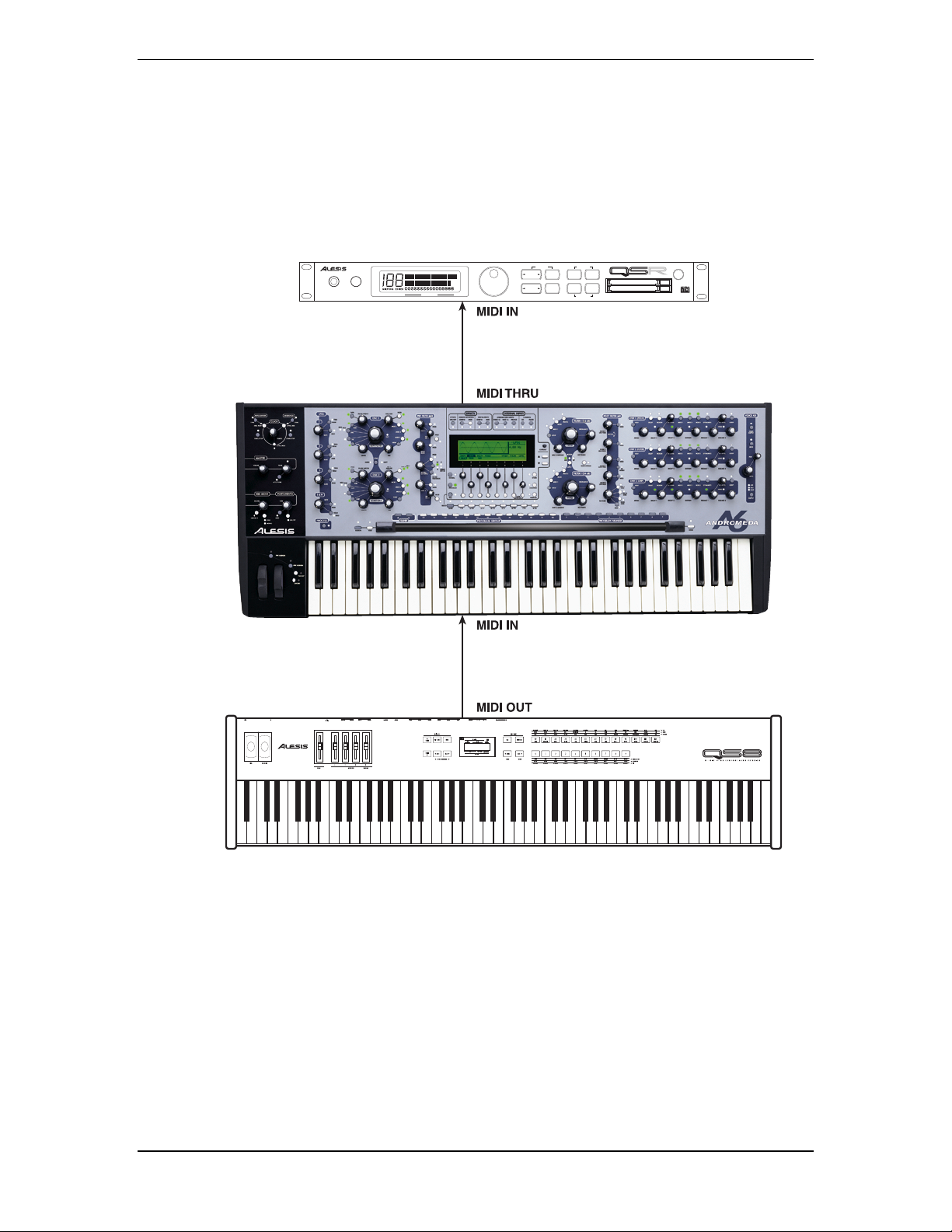
As a Master: If you intend to use the A6 as the master controller in your
rig, plug a standard MIDI cable into the A6’s MIDI OUT port. The
other end of this cable should plug into the
MIDI IN of the first
slave in the system. If there are several MIDI instruments in your
setup, connect
MIDI THRU from the first slave to the MIDI IN of the
second device and so forth to create a “chain”.
POWER
A
B
PHONES VOLUME
64 VOICE EXPANDABLE SYNTHESIZER MODULE
MIDI CHANNEL
PLAY MODE
VALUE
EDIT MODE
CURSOR
PROGMIXEDIT
DOWN UPSTOREMIDI CH
GLOBAL
COMPARE
BANK SELECT
PCMCIA EXPANSION CARDS
MIDI
ANDROMEDA A6 REFERENCE MANUAL 23
Page 26
Chapter 1: Getting Started
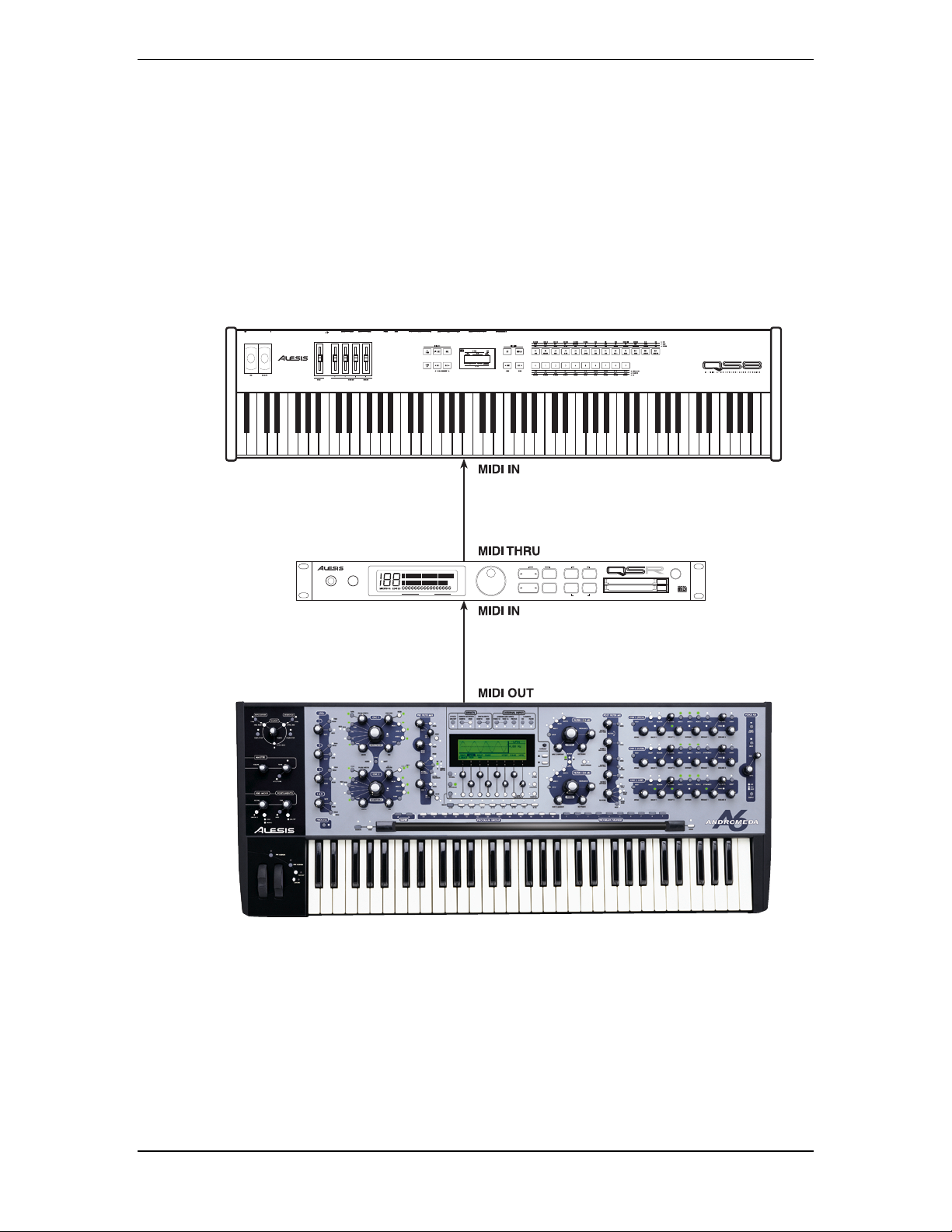
As a Slave: If you plan to control the A6 from another MIDI device, you’ll
need a
MIDI cable connected to its MIDI IN port.
You will also need a MIDI cable connected to the A6’s
if you plan to pass MIDI data from the master through the A6 to
other MIDI devices in your rig. Connect one end of the MIDI
cable to the A6’s
MIDI IN of the first device in the chain.
the
64 VOICE EXPANDABLE SYNTHESIZER MODULE
PHONES VOLUME
MIDI CHANNEL
MIDI THRU port and the other end of the cable to
PLAY MODE
VALUE
EDIT MODE
CURSOR
PROGMIXEDIT
DOWN UPSTOREMIDI CH
GLOBAL
COMPARE
BANK SELECT
PCMCIA EXPANSION CARDS
POWER
A
B
MIDI THRU
24 ANDROMEDA A6 REFERENCE MANUAL
Page 27
Chapter 1: Getting Started
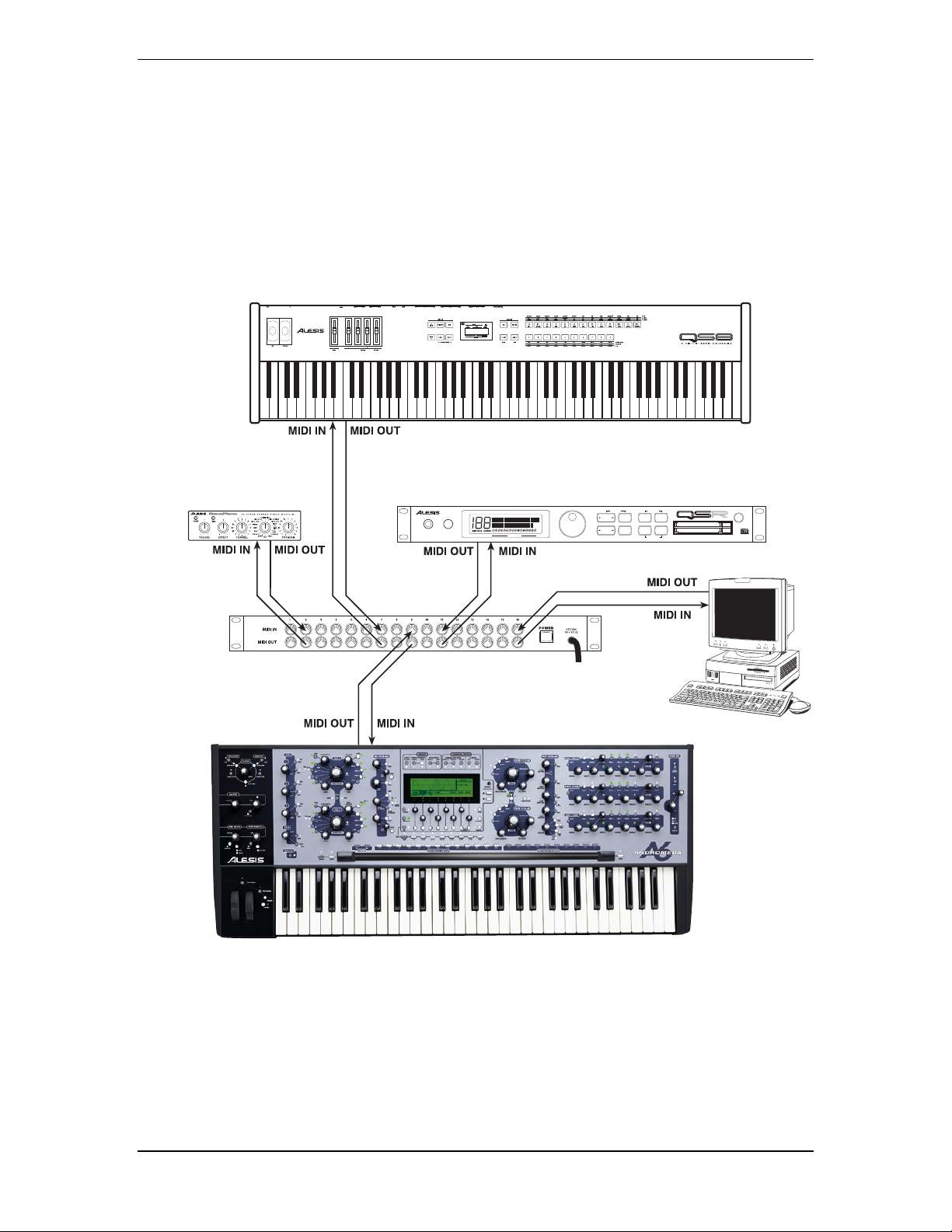
With a MIDI Patchbay: If you’re using a MIDI patchbay or “patcher” to connect all of
your MIDI devices centrally, the patcher will have a pair of MIDI
connectors for each MIDI device. The patcher’s back panel will
have a series of paired
MIDI OUT and MIDI IN ports for each device
in your rig (the A6 being one of them).
Connect the A6’s
same pair’s
MIDI OUT to the MIDI IN of one of the pairs. The
MIDI OUT connects to the MIDI IN of the A6. Consult the
patcher’s Owner’s Manual to find out how it routes MIDI data
among the devices connected to it.
PLAY MODE
PHONES VOLUME
64 VOICE EXPANDABLE SYNTHESIZER MODULE
MIDI CHANNEL
VALUE
EDIT MODE
CURSOR
PROGMIXEDIT
DOWN UPSTOREMIDI CH
GLOBAL
COMPARE
BANK SELECT
PCMCIA EXPANSION CARDS
POWER
A
B
This covers the basics of setting up the A6.
ANDROMEDA A6 REFERENCE MANUAL 25
Page 28

Chapter 1: Getting Started
QUICK START: PLAYING YOUR FIRST PROGRAM
AUTO TUNE
Now that it's all hooked up, there's one more thing you have to do. If you've jumped
the gun and played a few chords, you probably heard that the unit was way out of
tune. Because the Andromeda is a true analog synthesizer, and analog circuitry is
sensitive to temperature and other factors, each one of the sixteen voices (and the
oscillators and filters within each voice) must be tuned before playing. Luckily, the
Andromeda has a software routine that will do this for you.
To tune the Andromeda's voices automatically:
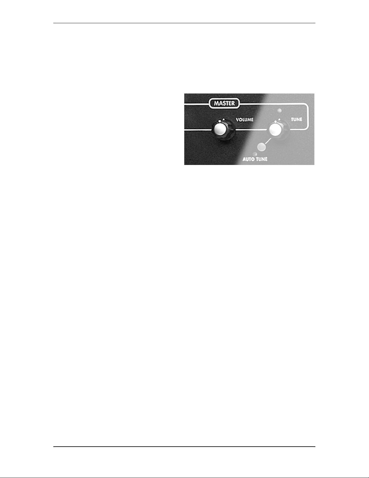
On the left side of the control panel above the Mod Wheel, find the MASTER section,
with a Volume and a Tune knob. Press the
will bring up the Auto Tune display. Press
process.
On the display, you will see each individual oscillator, pulse width, and filter tuned in
turn. This takes about three and a half minutes, during which you won't be able to play
the unit. (Later, you can save time by tuning only the oscillators if you wish, by pressing
the button under
OSCFRQ in the display.)
AUTO TUNE button beneath these, which
AUTO TUNE again to start the tuning
Once the unit is tuned, you'll see a chart showing the results of the tune. A “
under each voice number shows that the voice was properly tuned. There is one row
showing the VCA tune status and one row showing the Oscillator/Filter tune status
(more on this later). After the unit has warmed up some more, if you hear something
off-key, you may press
The A6 also automatically tunes unused voices in the background without
interrupting playing. This is called Background Tuning. In addition, the A6 monitors
the temperature of the analog hardware and adjusts tuning to compensate for
temperature changes. This is called Temperature Tuning. (More about turning these
on and off can be found in later sections of the manual.)
AUTO TUNE again.
T”
26 ANDROMEDA A6 REFERENCE MANUAL
Page 29
SELECTING PROGRAMS
You don't have to know what all the knobs do to enjoy the A6; it comes preprogrammed with hundreds of sounds. You can simply listen to these sounds and
find out more about them later. When playing the A6, the instrument operates in
one of two play modes: Program mode and Mix mode. In Program mode, the
keyboard plays a single sound across the entire keyboard. Program mode has 3
banks: User, Preset 1, and Preset 2. Each bank has 128 different Programs, so you
have a total of 384 Programs to audition. In Mix mode, it may play different sounds
in different ranges (a split), a stack of sounds on top of each other, or combination of
splits and stacks. There are two banks in Mix mode (one User and one Preset) for a
total of 256 Mixes. Between the two modes, you have 640 "patches" to select from.
To select Programs and Mixes:
1. To select a Program, make sure that the A6 is in Program mode: the LED next to
PROGRAM button should be on. If not, press the PROGRAM button.
the
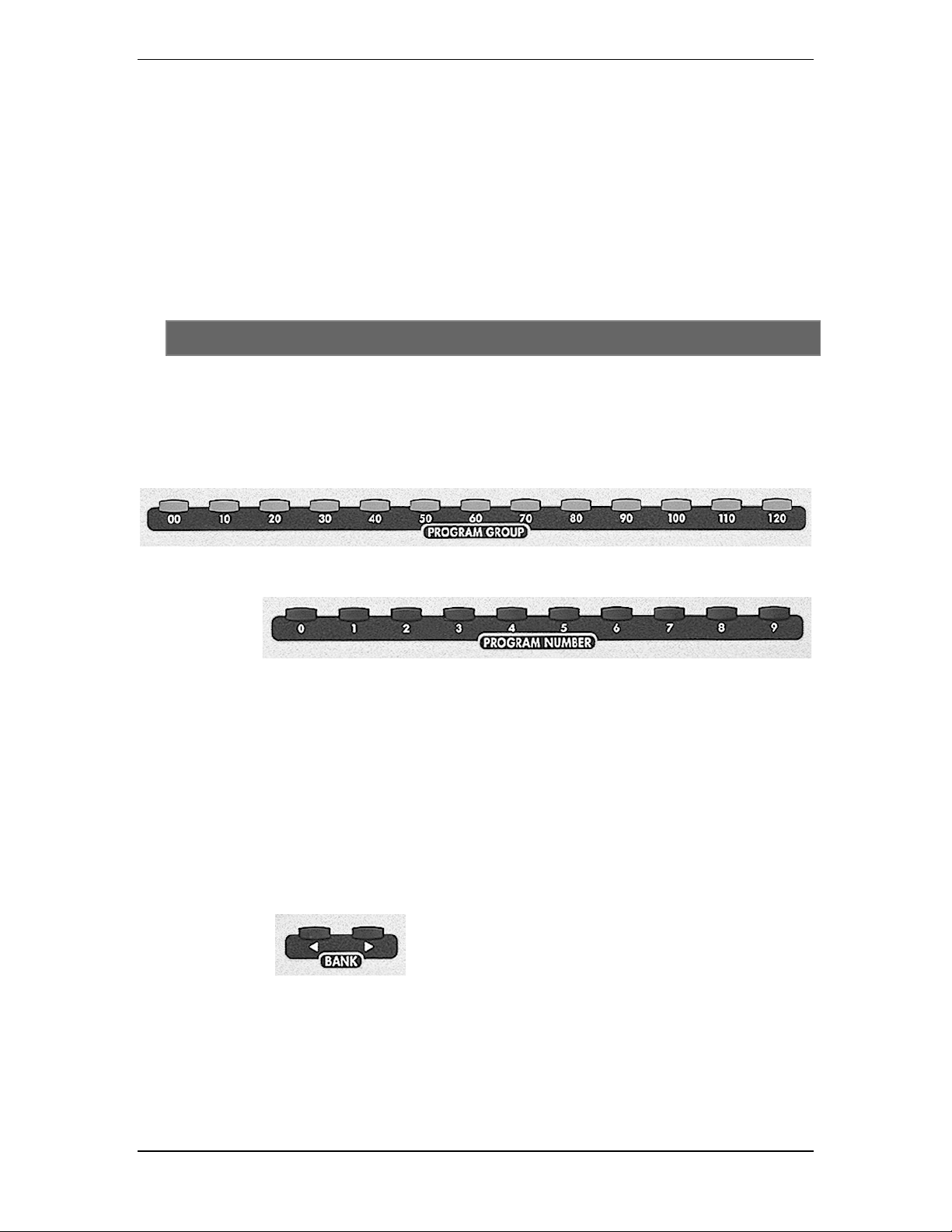
The easiest method of selecting Programs or Mixes to use the row of direct-select
buttons just above the Ribbon Controller. Pressing a 2-digit
selects the “tens group”...
Chapter 1: Getting Started
PROGRAM GROUP button
and pressing a single-digit PROGRAM NUMBER button selects the specific Program:
OR
To select a Mix, make sure that the A6 is in Mix mode: the LED next to the
MIX button should be on. If not, press the MIX button.
2. To select a specific Program, press a
NUMBER
selects Program
button. Pressing the “50” button, for example, plus the “8” button
58, Mix 58, or PROG 58 in a Mix Channel.
3. You can move among Banks by pressing the
For example, when the Andromeda is in
PROGRAM GROUP button then a PROGRAM
< BANK or BANK > button:
PROGRAM
mode, you have three Program Banks from which to
choose Programs: two factory Preset Banks and the
User Bank (where you store Programs that you create).
Use the
BANK buttons to switch among these three
Banks. Mix Mode works the same: when MIX Mode is
active, use the
BANK buttons to switch among the two
Mix Banks (one Preset and one User).
As you change programs, you'll notice various lights on the top panel will change.
Disregard this for now.
ANDROMEDA A6 REFERENCE MANUAL 27
Page 30
Chapter 1: Getting Started
MASTER VOLUME
And finally, adjust the level using the MASTER VOLUME on the left side of the control
panel. The
to do the same thing, but avoid using it for now.
MASTER VOLUME knob is a
The
global (affects the A6 in all
modes) volume control that
determines the final output
level of the unit’s
RIGHT stereo outs, the
HEADPHONE output and the two
AUX OUTs. It does not affect the
sixteen inidividual
OUTPUTS
MASTER VOLUME is post (comes
after) the
mixes and the VOICE MIX. This
means that any relative level
settings you make within the
Programs and Mixes are preserved.
VOICE MIX LEVEL on the right side is a programmable control—it may seem
MAIN LEFT and
. To use an audio term,
PRE and POST FILTER
VOICE
You operate this control by simply turning it: fully counter-clockwise shuts the audio
outputs off, fully clockwise is maximum.
The next chapter covers the basics of playing the A6: more detail about how to select
Programs and Mixes, understanding the various keyboard modes including setting
up splits and layers and using portamento, using the performance wheels and the
ribbon controller, using pedals and footswitches, and understanding the
CLOCK
section in using the sequencer and arpeggiator.
Chapter 2 will also devote much attention to the display, as it is the central focus of
the A6 when operating its controls.
28 ANDROMEDA A6 REFERENCE MANUAL
Page 31

Chapter 2: Playing the A6
CHAPTER 2:
PLAYING THE A6
Possibly the best way to get acquainted with the A6 is to dig in and start playing.
Feel free to skip around this Chapter if you need to get specific information quickly.
This Chapter deals specifically with functions you’re most likely to use when playing
the instrument:
• getting around the front panel
• understanding and using the display
• selecting Programs and Mixes
• setting up splits and layers
• using the Master controls
• exploring the various keyboard modes
• using the performance wheels and ribbon controller
• using pedals and footswitches
• the Clock section: using the sequencer and arpeggiator
Quite possibly the most fundamental skill you’ll need to acquire in using the A6
successfully is understanding the display. The essentials of operating the display are
covered in this Chapter, and as you use the display on a regular basis, its operation
will become much clearer. Once you get a hold of the concepts and procedures laid
out in this section, you’ll be ready to undertake the remaining tutorials in this book.
The one glaring omission of this Chapter – which is intentional, by the way – is a
tutorial on MIDI. If you need an explanation of this technology now, go to Chapter
12. The first half of Chapter 12 is devoted to the MIDI Specification, which serves as a
good starting point for those new to this system. Real-world applications with
numerous examples in connecting the A6 to other MIDI devices were covered in the
previous Chapter.
ANDROMEDA A6 REFERENCE MANUAL 29
Page 32

Chapter 2: Playing the A6
A BRIEF TOUR OF THE FRONT PANEL
The A6’s front panel contains a fairly large number of buttons and knobs, which is
probably a lot more than most players are used to seeing on a synthesizer these days.
The A6 is designed to make editing as easy and as quick as possible: the majority of
Program voice parameters exist on the front panel with a knob or button dedicated
exclusively to that function. Having dedicated knobs and buttons achieves the speed
goal by not forcing you to dig through layers and layers of functions on the display
just to make a simple or routine edit.
The speed of Program editing is enhanced further by the functionality of the display.
As we’ll discover in the next topic
screen employs a set of soft controls – controls that change function depending on the
current screen. These eight buttons and eight knobs are used to edit whatever is
being displayed. Therefore, the display area provides a second location where
Program editing can happen.
So you have a choice: you can make Program edits directly from any front panel
control, or you can do it in the display area. In either case, the display will change to
reflect the current edit you’re making. You can even lock the display so that it
doesn’t switch every time an edit is attempted. More on that later.
HOW FUNCTIONS ARE GROUPED
INTERACTING WITH THE DISPLAY, the A6’s LCD
Understanding how the A6’s functions are grouped will greatly enhance your ability
to learn and use the instrument. The following topics describe these function groups
– called modules – of the A6.
Program-Specific Functions
There are numerous functions within the A6 that deal only with the creating or
editing of Programs. In fact, most of the controls on the front panel that are in the
area above the keyboard (not including the display area) are Program functions.
The front panel is laid out such that each Module and its related parameters are
visually grouped by the artwork:
LFOs Display and Soft Controls* FILTER 1
PROCESS FILTER 2
OSC 1 EFFECTS* POST FILTER MIX
OSC 2 EXTERNAL INPUTS* ENV 1 (PITCH)
PRE FILTER MIX ENV 2 (FILTER)
These functions will be covered in detail in Chapter 4: A6 Overview and Chapter
5: Program Functions
seasoned analog synthesists who are familiar with earlier modular products, is that
each of the above function groups can be thought of as a “physical module minus the
patch cords”. In fact, you can “disconnect” some of these modules from the audio
and control paths by setting their values to zero, in effect turning them off. That’s
why they’re called “modules”.
* also available for Mixes. ENV 3 (AMP)
VOICE MIX
. But of particular importance to note now, especially for
Mix-Specific Functions
Mix mode, because of its nature in simply organizing existing Programs into splits,
layers and other Voice arrangements, has far fewer controls than those for
constructing the Programs themselves. Notice that Mix controls are conspicuously
absent from the A6’s front panel – you access these functions from the display. The
basics of layering and splitting are covered later in this chapter on page 47.
30 ANDROMEDA A6 REFERENCE MANUAL
Page 33

Chapter 2: Playing the A6
Mix mode is also used when the A6 is connected to a MIDI sequencer for
multitimbral recording and playback. Each Mix channel, the set of parameters that are
used to control a Program in the Mix, can be assigned to a specific MIDI Channel
with unique MIDI controller assignments.
Especially noteworthy of Mix mode is that it has its own set of programmable effects.
All of the effects available for enhancing Programs are included in this mode and are
fully independent and programmable per Mix. This is particularly useful when
constructing complex Mixes that use many different Programs. These functions are
covered in detail later in this manual in
Chapter 11: Mix Mode.
Global Functions
Global functions are those that affect the A6 no matter what mode it’s in. You can
think of global functions as “master” controls such as
TUNE
.
Also, there are certain MIDI functions that are global as well. Every MIDI instrument
or device has a setting called the Basic MIDI Channel. This sets the Channel on which
the instrument will normally transmit MIDI data, although the “upper” and “lower”
components of splits and layers can be set to transmit and receive on Channels other
than the Basic. Global Mode is covered later in this Chapter on page 49,
Global Mode.
But first, let's become familiar with the Andromeda's display and
soft controls.
MASTER VOLUME or MASTER
Using
ANDROMEDA A6 REFERENCE MANUAL 31
Page 34

Chapter 2: Playing the A6
INTERACTING WITH THE DISPLAY
Although the A6 has numerous knobs and buttons across its front panel, the display
(and its associated controls) is the central area to use when operating the A6. This
concept holds true in all modes: with few exceptions, virtually every front panel
knob and button are duplicated on-screen, and most of them will show their current
settings if appropriate.
DISPLAY FEATURES
As a general principle, the display will group a function’s parameters together on the
screen. This makes creating and editing Programs and Mixes much easier, as is
getting around in Global mode.
A group of parameters on the screen is called a display page. Some A6 functions have
more than one page because they have more parameters than can be displayed in the
available screen area. This is called a multi-page display and the active page’s title is
displayed on a page tab which resembles a tab in a notebook. The active parameter’s
title is displayed in white characters with a black-highlighted tab. This way, you will
always know which page and which parameter on that page is active.
In addition, the display’s usefulness is enhanced by depicting certain functions with
a graphic. Furthermore, the picture changes as you make adjustments to its parameters. Envelope shapes, LFO waves and Velocity curves are displayed in graph
form, just to name a few. A visual representation of the item(s) you’re changing not
only makes the editing process faster, it will (in many cases) assist you in
understanding the functionality of the parameters you’re working with.
32 ANDROMEDA A6 REFERENCE MANUAL
Page 35

BASIC DISPLAY FUNCTIONS
In its normal operating mode, the display will react to virtually any change you
make to any of the front panel controls. When you turn a knob or press a button, the
display will recall that parameter’s page and select the parameter for editing. This
feature of the A6 will save you an enormous amount of time and frustration when
making changes and minimizes the risk of “getting lost” when editing many
parameters at the same time.
While this feature of the A6 is quite useful when working with individual
parameters, you may want to display a particular module. In this case, press its
button. This will display the selected module – OSC 1, OSC 2, FILTER 1, FILTER 2, ENV 1,
ENV 2 or ENV 3, etc. – and the last parameter that was used in that module will be the
active one. You can then proceed to make your edits from either the screen’s controls
or the module’s dedicated front panel controls.
Chapter 2: Playing the A6
VIEW
The advantage of the
VIEW button is that you can select a module and view its
current settings without changing any of its parameters. If you turn one of the front
panel knobs, its value will change. So if you just want to see the module’s current
settings without making changes, use the
VIEW button.
On the other hand, the advantage of a module’s dedicated front panel controls is that
you can make edits to its most commonly used parameters quickly just by turning
a knob. The choice is yours.
Soft Controls
Directly beneath the display is a series of eight untitled knobs and buttons numbered
1 through 8. These are soft controls – controls that change function depending on the
current screen. Soft controls, therefore, obtain their functional identity or
“personality” from the pages and parameters being displayed: the current function of
any knob or button is determined by what is on the display directly above the
control. There are three rows in most displays:
• the bottom row of the display is called the Page Row. It shows the names of
display pages that can be called up by pressing the button beneath the page
tab.
• the second row of text shows the function of each knob. We’ll refer to this
row of text as the Parameter Row.
• the third row of text (in
each parameter. We’ll refer to this row of text as the Value Row.
reversed text like this) shows the current value of
Tip: Although you can select any parameter simply by turning its corresponding soft
knob, this action also changes the parameter’s value which isn’t always
desirable. Sometimes you just want to review the current settings of the
parameters on a page without changing anything. On many pages, you can
select a parameter without changing its value by pressing its page’s soft button.
ANDROMEDA A6 REFERENCE MANUAL 33
Page 36

Chapter 2: Playing the A6
Modes of Operation
Let’s start at the beginning and discuss the three basic operating modes of the A6 and
how the display keeps you informed of what’s going on.
All of the operations of the A6 are grouped into three operating modes: Program
mode, Mix mode and Global mode. You can access only one of these modes at a time,
but switching among the three is as easy as pressing a button.
Use the three buttons on the lower left-hand corner of the display area to initiate the
desired mode. When pressed, a mode button’s associated LED will light:
• pressing
PROGRAM initiates Program mode where the A6’s single programs
are played via the keyboard or MIDI, and where you edit existing Programs
or create new ones from scratch. This is one of the A6’s two Play modes; the
other one is Mix mode, described next.
• pressing
MIX initiates Mix mode where the A6’s Mix programs are played via
the keyboard or MIDI, and where you edit existing Mixes or create new ones
from scratch. A Mix is made up of existing single Programs and is the mode
you use for creating layers, splits or complex sound combinations, and for
MIDI control.
• pressing
GLOBAL initiates Global mode where you control the A6’s global
functions and master settings. These functions affect the A6 regardless of
what Play mode the A6 is in. Included in this mode are items such as setting
the MIDI Basic Channel and MIDI Controller Numbers, monitoring voice
activity, and so forth.
Data Banks: How the A6’s Sounds Are Organized
The following block diagram illustrates how the A6’s memory is organized among
the three operating modes we just discussed.
GlobalMixProgram
Sequencer & Arpeggiator
Keyboard Modes
Portamento/LFOs/S & H
Tracking Generator
Voltage Controlled Oscillators
Pre Filter Mix
Filters
PROGRAM SETTINGS
Post Filter Mix
Envelopes
Voice Outputs & Mix
Effects Send Outputs & Mix
Modulation Matrix
MIX CHANNEL 1
Program
Settings
MIX CHANNEL 2
Program
Settings
MIX CHANNEL 3
Program
Settings
MIX CHANNEL 14
Program
Settings
MIX CHANNEL 15
Program
Settings
MIX CHANNEL 16
Program
Settings
Mix Channel
Parameters
Mix Channel
Parameters
Mix Channel
Parameters
Mix Channel
Parameters
Mix Channel
Parameters
Mix Channel
Parameters
Global Tune & Transpose
Global MIDI Filtering & Assign
Wheel, Pedal, Ribbon and
MIDI Continuous Controllers
Assignments
Edit Preferences
EXTERNAL INPUTS
CV/Audio/Hardware Routing
Analog Distrotions Configurations & Parameters
EFFECTS
Digital Effects Configurations & Parameters
EXTERNAL INPUTS
CV/Audio/Hardware Routing
Analog Distrotions Configurations & Parameters
EFFECTS
Digital Effects Configurations & Parameters
MASTER CLOCK SETTINGS MASTER CLOCK SETTINGS
34 ANDROMEDA A6 REFERENCE MANUAL
Page 37

Chapter 2: Playing the A6
Throughout this manual, we’ll be using the following terms to describe the memory
capabilities of the A6:
•A Program bank refers to an entire bank of Programs.
•A Mix bank refers to an entire bank of Mixes.
•A User bank (there’s one for Programs and one for Mixes) refers to a data
bank that uses RAM for storage and can be edited. You can think of this of
bank as your “work space”: individual Programs and Mixes can be edited and
stored, replaced, copied and so forth.
•A Preset bank refers to a data bank – either Program or Mix – in Flash ROM.
The A6’s Preset banks (there are three of them) are commonly called “factory
presets” on many other instruments. These banks – two Preset Program banks
and one Preset Mix bank – contain Programs and Mixes developed for the A6
by the Alesis Sound Design team.
Unlike Preset banks in many other synths, the A6's Preset banks can be
customized by the user, but only as an Entire Bank copy operation. This
means that, unlike the User banks, you cannot selectively copy just one
Program or Mix to this bank. The entire bank must be over-written at once.
•A Card bank refers to a data bank of memory provided by a PCMCIA card in
the A6's back-panel card slot. An SRAM card allows the same options for
storage as found for the User bank. The card may allow for a Program Bank
only, several Mix banks, or a combination, depending on its size.
The A6’s memory capacity is arranged as follows:
Program mode:
• 2 Preset Program banks of 128 Programs (256 total)
• 1 User Program bank of 128 Programs
Mix mode:
• 1 Preset Mix banks of 128 Mixes each
• 1 User Mix bank of 128 Mixes
Memory Functions
Each of the two play modes – Program and Mix – contain two memory functions that
are used when editing existing Programs or Mixes, or creating new ones. When
pressed, a memory button’s associated LED will light:
STORE button allows you to save a Program or Mix that you’ve edited or
• the
created into the current program number, or copy it to another memory
location. The procedure for saving edited Programs and Mixes is detailed on
page 43.
• pressing
editing so that you can compare the edited version with the original. This
button is inactive if the current program hasn’t been edited (there’s nothing
different to compare).
Program mode contains a third memory-related function called
when creating new Programs and is only active in Program mode. Pressing this
button causes the A6 to exit the current Program and create a new Program based on
the current settings of all front panel controls. While this new program may not
sound like anything useful – the knobs could be positioned in strange settings – it
provides a good starting point for a new program.
COMPARE recalls the stored version of the Program or Mix you’re
MANUAL that’s used
ANDROMEDA A6 REFERENCE MANUAL 35
Page 38

Chapter 2: Playing the A6
LOCK Function
While many of the A6’s pages make use of all eight knobs and buttons, many do not.
You may notice that sometimes knobs and buttons will become inactive because the
display doesn’t need them. But there are two soft buttons –
active. They are used to lock the display.
As mentioned at the beginning of this topic, the display will react to virtually any
change you make to any of the front panel controls. This causes a lot of display
switching and can be distracting. If you want to prevent the display from switching
screens when performing numerous edits, press soft buttons
will lock the display in its current screen, and
knobs 4 and 5. You can continue to make adjustments to any parameter, but the
display stays put. Press
▲ and ▼ Arrows
For the majority of parameters in the A6, numeric values are displayed with
fractional amounts, represented by the digits to the right of the decimal point. This
allows for very precise adjustments to be made to parameters that support fractional
values. The
adjustments to any parameter that is displayed with a fractional value.
Holding an arrow down scrolls the values. You’ll notice that the changing values will
accelerate the longer you hold the arrow button down.
▲ (increment) and ▼ (decrement) arrows are used to make fine
7 and 8 – that are always
7 and 8 together. This
DISPLAY LOCKED will flash over soft
7 and 8 again (or any VIEW button) to turn this function off.
Double-Arrow Reset
Pressing both arrow buttons together will either set the selected parameter to zero
or to a useful default or neutral value. For example, if the
SQR wave’s WIDTH
parameter is selected, pressing both arrows together sets its value to 50%. If FILTER 2
KEY TRACK
is selected, pressing both arrows together sets its value to 50. Generally,
most parameters with a 0 to 100 or a -100 to +100range will reset to 0.
CONTRAST Control
The CONTRAST knob above the ▼ and ▲ arrows is used to adjust the contrast of the
display.
The MIX SELECT Button Group
The row of rectangular buttons just below the display area are used to select the
Programs within a Mix. When a Mix Channel is ON, its associated LED will light.
When a Mix Channel is currently selected for editing in the display, its LED will
blink.
When the A6 is in Mix mode, pressing one the
a specific Mix Channel – the group of settings that affect each Program in a Mix (the
Program number, its transpose value, its individual MIDI Channel, etc.). Pressing a
numbered button alone selects Mix Channels
while pressing a numbered button selects Mix Channels 9 through 16.
1/9 through 8/16 buttons selects
1 through 8. Pressing and holding SHIFT
36 ANDROMEDA A6 REFERENCE MANUAL
Page 39

Chapter 2: Playing the A6
Table of Display Functions
The following table summarizes the functions of the display’s knobs and buttons:
NAME FUNCTION
GLOBAL button Enters Global mode, displays Global screen.
PROGRAM button Enters Program mode, displays Program screen.
MIX button Enters Mix mode, displays Mix screen.
Enters Store mode, Copy mode for Programs, Banks, and Effects, SysEx mode, and the INIT
STORE button
COMPARE button
MANUAL button Enters Manual mode: every knob position on the front panel is read by the A6 and made current.
MIX button group Group of buttons for selecting the current Mix Channel within a Mix:
SHIFT button Toggles between the Mix Channels 1-8 and 9-16.
1/9 – 8/16 buttons
function used to reset the A6 User banks; displays the screens associated with each of the
above functions.
Enters Compare mode: when editing, the stored versions of the current Program or Mix (including
Distortion and Effects) are recalled permitting a comparison to be made with the edited
versions.
Pressing once selects the desired Mix Channel. For the current Mix Channel, pressing again
toggles the Mix Channel on or off. When a Mix Channel is on, its button’s LED will blink when
that Mix Channel is selected.
“Soft Buttons”
“Soft Knobs”
▲ and ▼ buttons
LOCK DISPLAY
button combination
Eight buttons below the display that select the page shown on the Page row (the lowest row of
text in the display).
Eight knobs below the display whose functions are determined by what is currently being
displayed on the second row of text from the bottom (the Parameter row).
Step adjusts the highlighted value for the current parameter. Pressing both arrows together resets
the current parameter to zero, a midpoint or a useful default value
Soft Buttons 7 and 8 pressed together will lock the current display screen. The words
DISPLAY LOCKED will flash in the display.
ANDROMEDA A6 REFERENCE MANUAL 37
Page 40

Chapter 2: Playing the A6
SELECTING PROGRAMS AND MIXES
When playing the A6, the instrument operates in one of two play modes: Program
mode or Mix mode. One method of selecting Programs or Mixes is using the row of
direct-select buttons just above the Ribbon Controller. Pressing a 2-digit
GROUP
button selects the “tens group”...
... and pressing a single-digit PROGRAM NUMBER button selects the specific Program or
Mix:
1. To select a Program, make sure that the A6 is in Program mode: the LED next
PROGRAM button should be on. If not, press the PROGRAM button.
to the
OR
To select a Mix, make sure that the A6 is in Mix mode: the LED next to the
button should be on. If not, press the MIX button. Also, in Mix mode you can
work with the individual Programs that are contained within a Mix (the
individual Programs that comprise a Mix are referred to as Mix Channels).
2. To select a specific Program, Mix or assign a Program to a Mix Channel, press
a
PROGRAM GROUP button then a PROGRAM NUMBER button. Pressing the “50”
button, for example, plus the “
Program mode, Mix
58 when in Mix mode or assigns Program 58 to the
selected Mix Channel when Mix mode’s
paragraph for details:
8” button selects Program 58 when the A6 is in
PROG page is displayed. See the next
PROGRAM
MIX
3. To assign a specific Program to a specific Mix Channel within a Mix, press
MIX
to enter Mix mode, then press one of the SELECT buttons to select a Mix
Channel. Press soft button 6 to display Mix mode’s
PROG page is being displayed, pressing a PROGRAM GROUP and/or a
PROGRAM NUMBER assigns that Program to the current Mix Channel. Don’t
forget to turn the Mix Channel on (press the Channel’s
PROG page. While the
SELECT button if its
LED is off).
4. You can move among Banks by pressing the
< BANK or BANK > button:
When the Andromeda is in Program mode, you have three Program Banks
from which to choose: two factory Preset Banks and one User Bank (where
you store Programs that you create). Use the
BANK buttons to switch between
these Banks. Mix Mode works the same: when MIX Mode is active, use the
BANK buttons to switch among the two Mix Banks (one Preset and one User).
The second method of selecting a Program, Mix or Mix Channel involves the display
and soft knobs and is covered in the next topic.
38 ANDROMEDA A6 REFERENCE MANUAL
Page 41

PROGRAM MODE PARAMETERS
Pressing the PROGRAM button displays the Program mode display screen. As with all
other A6 functions, the page and parameter that was last selected will be recalled.
The following table summarizes the Program mode parameters:
Chapter 2: Playing the A6
SOFT KNOB
PAGE TAB
PROG BANK NUMBER
DIR BANK NUMBER
1 2 3 4 5 6 7 8
PROG and DIR Page Parameters
The PROG (Program) page provides another method to select Programs in addition to
the Direct Select buttons. When this page is being displayed, use soft knob
the bank and soft knob
The
DIR (Directory) page soft knobs operate the same as in the PROG page. The
difference is that the
synthesizer, and shows ten names at a time.
Tip: While either of these two pages are being displayed, you can still use the Direct
Select buttons as well as the soft knobs to select sounds.
MIX MODE PARAMETERS
Pressing the MIX button displays the Mix mode display screen. As with all other A6
functions, the page and parameter that was last selected will be recalled. The
following table summarizes the Mix mode parameters:
1 to select
2 to select the specific Program number.
DIR page provides a directory-style listing of all Programs in the
SOFT KNOB
PAGE TAB
MIX BANK NUMBER ENABLE
MIXDIR BANK NUMBER
KBD KBD LO KBD HI ENABLE
PROG LEVEL PAN OUTPUT SEMI CENTS MIDI CH
CNTL
SOLO
1 2 3 4 5 6 7 8
PCHWHL MODWHL AFTCH SUSPDL EXTSW EXTPDL RIBBON - KBD -
MID IN MIDOUT MID CC MIDVOL MIDPGM MIDAFT
The DIR page in Mix mode operates exactly the same as the parameters in Program
mode. For descriptions of this parameter, see above.
ANDROMEDA A6 REFERENCE MANUAL 39
Page 42

Chapter 2: Playing the A6
The pages unique to Mix mode are MIX, KBD, PROG, CNTL and SOLO, described as
follows:
MIX Page Parameters
PAGE PARAMETER
OPTIONS
or RANGE DESCRIPTION
MIX
BANK - USER -
NUMBER 000 ··· 127
ENABLE
KBD Page Parameters
The abbreviation for “Keyboard,” this Mix page contains parameters that determine
the keyboard range of the current Mix Channel and allow you to turn the keyboard’s
control of the Mix Channel on or off.
PAGE PARAMETER
KBD
KBD LO
Low note limit *
KBD HI
High note limit *
PRESET 1
ON, OFF
OPTIONS
or RANGE
C0 ··· G10
C0 ··· G10
This parameter displays the current Mix Bank.
Use soft knob
1 or the BANK select buttons to
change Banks.
This parameter displays the number of the
current Mix in the current Mix Bank. Use soft
2 or the PROGRAM GROUP and PROGRAM
knob
NUMBER
buttons to change Mixes.
Use soft knob 8 to turn the currently selected
Mix Channel on or off.
DESCRIPTION
The lowest note on the keyboard that this Mix
Channel will play on.
The highest note on the keyboard that this Mix
Channel will play on.
ENABLE ON, OFF
Turns keyboard control of this Mix Channel on
or off. This is useful for setting up a Mix Channel
to be played by MIDI In only and not to be
affected by the A6’s keyboard.
* The KBD LO and KBD HI settings define the keyboard range or zone of the Mix Channel. These
are the parameters you use when setting up splits and layers, as well as other specialty
keyboard configurations. See page 47 later in this Chapter for the full story.
40 ANDROMEDA A6 REFERENCE MANUAL
Page 43

PROG Page Parameters
The abbreviation for “Program,” this page is where you set the level, pan and output
jacks, transpose and fine tuning amounts, and MIDI Channel settings for the selected
Mix Channel.
This is also where you can select a Program for the Mix Channel using the PROGRAM
GROUP and PROGRAM NUMBER buttons.
PAGE PARAMETER
OPTIONS
or RANGE
Chapter 2: Playing the A6
DESCRIPTION
PROG
LEVEL 0 ··· 100
PAN -100 ··· +100
OUTPUT - OFF -
MAIN
AUX
SEMI -60 ··· +60
CENTS -100 ··· +100
MIDI CH 1 ··· 16
Sets the output level of the current Mix Channel.
Sets the “placement” of the Mix Channel’s
output in the left-to-right stereo panorama.
-100
is full left, +100 is full right and 0 is center.
Routes the audio output of the current Mix
Channel to either the rear panel
jacks, the
AUX jacks or off. Note that the
headphones will be active only when
MAIN output
MAIN is
selected in the display.
Sets the transpose amount of the current Mix
Channel in semi-tones, ± 5 octaves.
Sets the transpose amount of the current Mix
Channel in semi-tones, ± 5 octaves.
Sets the MIDI Channel that the current Mix
Channel will use to send and receive.
ANDROMEDA A6 REFERENCE MANUAL 41
Page 44

Chapter 2: Playing the A6
CNTL Page Parameters
The abbreviation for “Controllers”, this page permits you to enable/disable local and
MIDI controllers for the selected Mix Channel.
The parameters on this page determine whether or not the displayed controllers
affect the currently selected Mix Channel. Use the parameter’s corresponding soft
knob to turn the function on or off.
PAGE PARAMETER
OPTIONS
or RANGE
DESCRIPTION
CNTL
Page 1
PCHWHL ON, OFF
MODWHL
AFTCH ON, OFF
ON, OFF
Enables, disables the A6’s Pitch Wheel.
Enables, disables the A6’s Modulation Wheel.
Enables, disables keyboard Aftertouch. MIDI In
aftertouch is turned off or on in Page 2, below.
SUSPDL ON, OFF
Enables, disables the rear panel SUSTAIN jack and
MIDI In sustain pedal control.
EXTSW ON, OFF
EXTPDL ON, OFF
RIBBON ON, OFF
- KBD - ON, OFF
Enables, disables the rear panel SWITCH jack.
Enables, disables the rear panel CC PEDAL jack.
Enables, disables the A6’s Ribbon Controller.
Enables, disables the A6’s keyboard.
The CNTL parameter group contains 16 parameters, displayed eight at a time. Press soft button
7 to toggle between the two display sub-pages.
CNTL
Page 2
MID IN ON, OFF
MIDOUT ON, OFF
Enables, disables MIDI In control of the current
Mix Channel.
Enables, disables MIDI Out control from the
current Mix Channel.
MIDCC ON, OFF
Enables, disables MIDI continuous controller
commands such as sliders and knobs on another
MIDI device.
MIDVOL ON, OFF
MIDPGM ON, OFF
Enables, disables MIDI volume control.
Enables, disables MIDI program change
commands.
MIDAFT ON, OFF
Enables, disables MIDI Aftertouch.
SOLO function
This is not a “page”, actually; you can press Soft Button 8 to solo a Mix Channel
when you’re on any of the pages of Mix mode. This “solos” the currently selected
Mix Channel (indicated by the green blinking LED over the SELECT button) so you
can concentrate on one layer of a Mix without hearing the others.
42 ANDROMEDA A6 REFERENCE MANUAL
Page 45

Chapter 2: Playing the A6
STORING EDITED PROGRAMS AND MIXES
Chapters 5 through 8 explore the details of editing existing Programs and Mixes, and
provide all the information for creating completely new ones. When a Program or
Mix has been edited or a new one is created, you’ll need to save your work. This is
where
STORE mode comes in.
STORE mode allows you to save into the current Program or Mix number (also
referred to as a memory location), or copy it to another memory location in the User or
Card bank. Note that you cannot store to a memory location in any Preset bank.
STORE MODE PARAMETERS
SOFT KNOB
PAGE TAB
1
PROG
DIR BANK NUMBER
COPY TYPE SRCBNK SRCNUM* MIXCHN* DSTBUF* DSTBNK* MIXCHN*
INIT PROGS MIXES
SYSEX BANK NUMBER RCV-TO SEND
CARD INIT
NAME BANK NUMBER CHAR 0-9 UPPER LOWER NAMES <- ->
1 2 3 4 5 6 7 8
BANK NUMBER
1
The first tab, displayed here as PROG, shows that the A6 is in STORE mode for Programs.
When the A6 is in
* These parameters appear in the
STORE mode for Mixes, this tab will display MIX.
COPY page depending on the TYPE chosen.
TO STORE A PROGRAM OR MIX TO MEMORY:
1. Press STORE. For Programs (Mixes), the screen will display the message:
SELECT PROGRAM (MIX) AND BANK AND HIT STORE TO SAVE
2. To store the current edited version of a Program or Mix to the same memory
location, press
Program or Mix that is currently in this (User or Card) memory location.
3. To store an edited Program or Mix to a different memory location, use soft
knob
1 (or the BANK buttons) to change Banks and use soft knob 2 (or the
PROGRAM GROUP and PROGRAM NUMBER buttons) to change the Program or
Mix number. The press
that is currently in this User or Card memory location.
STORE again. This will overwrite the old version of the
STORE again. This will overwrite the Program or Mix
To abort the store, press either the
PROGRAM or the MIX button.
If you want to re-arrange the order of Programs and Mixes, you can use this
procedure to copy Programs and Mixes that you just want to move around – they
don’t have to be edited to be copied. On the other hand, the
STORE function has a DIR
page and a COPY page that are designed to make these operations easier as described
below.
ANDROMEDA A6 REFERENCE MANUAL 43
Page 46

Chapter 2: Playing the A6
DIR Store Procedure
When you press the STORE button the first time to initiate a store, you can press soft
button 2 to enter the
Programs or Mixes by name. This way, if you want to store a Program or Mix to
another memory location, you can see in advance which Program or Mix will be
overwritten.
DIR (“Directory”) page. Here you can view the entire list of 128
Use soft knob
complete the store. To abort the store, press either the
COPY Page Parameters
PAGE PARAMETER
COPY
TYPE PRG BANK
SRCBNK
Source Bank
2 to select the destination Program (or Mix). Press STORE again to
PROGRAM or the MIX button.
OPTIONS
or RANGE
DESCRIPTION
Copy the entire Program/Mix Bank to the
MIX BANK
PRG DFX
MIX DFX
PRG AFX
MIX AFX
MIX CHAN
Destination Bank. This is the only way to change a
Preset Bank.
Copy the Digital Effects parameters of the
selected Program or Mix to the selected Edit
Buffer.
Copy the Analog Distortion parameters of the
selected Program or Mix to the selected Edit
Buffer.
Copy a Mix Channel to a different Mix Channel
in the Edit Buffer.
USER
PRESET 1
PRESET 2*
CARD*
Selects the Bank you want to copy from.
SRCNUM
Source Number
O-127
Selects the number of the Program or Mix you
want to copy from. This has no effect in Program
or Mix Bank copy mode.
DSTBNK
Destination Bank
DSTBUF
Destination Buffer
USER
PRESET 1
PRESET 2*
CARD*
MIXBUF
PRGBUF
Selects the Bank you want to copy to, that will be
overwritten by pressing
COPY then STORE.
Appears only in Program or Mix Bank copy mode.
Selects the Edit Buffer you want to copy to, that
will be overwritten by pressing
STORE.
COPY then
Appears only in Program or Mix DFX or AFX copy
mode.
MIXCHN
Mix Channel
1-16
In MIX CHAN COPY mode, this appears in two
places. Turn Soft Knob 4 to select the source,
and Soft Knob 8 to select the destination Mix
Channel.
* There is no Preset 2 option when a Mix is the source, and no Card unless an initialized card is in the
memory slot.
44 ANDROMEDA A6 REFERENCE MANUAL
Page 47

Chapter 2: Playing the A6
COPY Procedure
To copy an item, press STORE then press soft button 3. Use soft pot knob 1 to select
the type of item to copy (Program Bank, Program Digital FX settings, etc.) Select the
source using soft knob
2. Select the destination using soft pot 7. Press STORE twice to
execute the copy.
INIT Procedure
You can initialize, or reset, all Programs in the User Bank to the - A6 Default
Program -
resulting in a basic, rather “plain” sounding Program. By the same token, you can
reset all Mixes to their default values as well.
, a program that returns all program settings to their default values
To accomplish this, press
turn soft knob 1; to initialize all Mixes, turn soft knob
will prompt you to press
initialization, press either the
STORE then press soft button 4. To initialize all Programs,
2. In either case, the display
STORE again to complete the reset. To abort the
PROGRAM or the MIX button.
Be careful: initialization cannot be reversed. There is no “Undo” like there is on
personal computers.
Storing Programs and Mixes using the SYSEX Page
To store Programs and Mixes to an external MIDI device such as a sequencer or MIDI
data storage device, use a System Exclusive dump. You can set the kind of SysEx
dump you want to send by pressing Soft Button
5, the SYSEX page of Store mode.
This page is also where you set how SysEx messages will be received. For details on
using System Exclusive messages for storing to an external MIDI device, see
12: MIDI
.
CARD Page
You can expand the Program/Mix memory of your Andromeda by plugging in PC
Card Type 1 SRAM cards, available from your Alesis dealer. The
show you the size and type of card currently in the memory slot on the rear panel.
The only other function of the page is
INIT, used primarily when a card is brand
new and needs to be initialized to the A6's card format, but also to erase all Programs
or Mixes on a card.
CARD page will
Chapter
TO INITIALIZE A CARD:
1. Insert a PCMCIA Type 1 SRAM memory card (from 256k to 2MB in size) into the
card slot on the back of the unit.
2. Press
3. Turn Soft Knob 1 (
4. Press
ANDROMEDA A6 REFERENCE MANUAL 45
STORE. Press Soft Button 6, CARD.
INIT) all the way around until "HIT STORE TO INIT RAM
CARD
" shows in the display.
STORE. Follow the prompts for whether you want the card to store only
Programs, Mixes, or both. (These may not be available if the card is less than
512k in size.)
Page 48

Chapter 2: Playing the A6
NAME Page Parameters
The NAME page contains parameters that allow you to quickly and easily change the
name of the selected Program or Mix. In addition, you can also change the
destination Bank and Program/Mix number like you can in the
PAGE PARAMETER
PROG page.
OPTIONS
or RANGE DESCRIPTION
NAME
BANK - USER -
PRESET 1
NUMBER 000 ··· 127
CHAR SPACE - z
0-9 0 - 9
UPPER
LOWER a ··· z
*
NAMES
<- ->
A ··· Z
Various (see
below)
This parameter displays the current Program or
Mix Bank. Use soft knob
1 or the BANK select
buttons to change Banks.
This parameter displays the number of the
current Program or Mix in the current Bank. Use
soft knob
NUMBER
2 or the PROGRAM GROUP and PROGRAM
buttons to save to a different Program or
Mix number.
Use soft knob 3 to select a character.
Use soft knob 4 to select numerals 0 through 9
only.
Use soft knob 5 to select upper-case letters A
through Z only.
Use soft knob 6 to select lower-case letters a
through z only.
Soft knob 7 allows you to select from among a
list of 89 preset Program/Mix names to save you
time.
Use soft knob 8 to select the character you want
to change.
* The names available for selection are:
Alien Boomy Dark Fretless Lonely Oboe Reverse String Trash
Analog Brass Decay FM Mod Loose Pad RingMod Stupid Twisted
Angry Bright Deep Guitar Lost Phat Sax Sync Unison
Another Chromatic Delayed Horns Low Plucked Sequence Synth Velocity
Awesome City Dingy Hammer MIDI Piano Simple Technox Violin
Arpeg Crash Dual Hard Monster Piercing Sloppy Timed Watery
Attack Crispy Edge Harp Moon Porta Slow Thick Whirling
Bass Crying Fast Harmonic Morph PW Mod Solo Thunder Whistle
Bell Cutting Fat Junky Octave Random Soft Tight Zither
Blues Cymbal Flute Leslie Organ Retro Sparkle Toy
Blank
46 ANDROMEDA A6 REFERENCE MANUAL
Page 49

SETTING UP SPLITS AND LAYERS
Splits and layers are constructed from Mix Channels in Mix mode. So make sure that
the A6 is in Mix mode: the LED next to the
MIX button.
TO SET UP LAYERS OF PROGRAMS IN MIX MODE:
To create a layer, we’ll “stack” one Mix Channel on top of another. This is
accomplished by assigning the same keyboard range to both Mix Channels. This
effectively creates two note commands for every one key that is played on the A6’s
keyboard:
1. Press the
on the right side of the screen. If
knob
1/9 button. The display will show you the STATUS of Mix Channel 1
8 to turn Mix Channel 1 ON. The LED above the 1/9 button will blink.
MIX button should be on. If not, press the
OFF, press the 1/9 button again or use soft
Chapter 2: Playing the A6
2. Do the same for Mix Channel 2: press the
Channel 2 is OFF, press the
Channel 2
ON. The LED above the 2/10 button will blink; the LED above the 1/9
2/10 button again or use soft knob 8 to turn Mix
2/10 button. If the the status of Mix
button will light steady.
3. We only want to use two Mix Channels, so make sure that the LEDs above the
remaining
MIX SELECT buttons are off. Also, press the SHIFT button to make
sure that Mix Channels 9 - 16 are off as well.
4. Next, we will assign a different Program to each Mix Channel and adjust the
performance parameters. Press the
soft button
a. Use the
6 to enter the PROG page:
PROGRAM GROUP and PROGRAM NUMBER buttons to assign a
1/9 button to select Mix Channel 1. Press
Program to this Mix Channel.
b. Use soft knob 1 to set the Mix Channel’s output level and soft knob
its panning position. For our purposes in this example, set
PAN to -100 (all
2 to set
the way left).
c. Use soft knob
MAIN, so just make sure that MAIN is selected. Settings for SEMI, CENTS,
to
MIDICH are optional for this example.
and
d. Press soft button
C-1 and KBD HI is set to G9. These are the default settings for a Mix
3 to set the OUTPUT to MAIN. Mix Channels normally default
5 to display the KBD page. Make sure that KBD LO is set to
Channel’s keyboard range which spans the entire MIDI note range of 0 -
127. Last, make sure that
e. Settings on the
CNTL page for MIDIIN and MIDOUT are optional for this
ENABLE is set to - ON -.
example.
5. Press the
PROG page. Follow sub-steps a. through e. above in setting up Mix Channel 2
with the exception of step b. where you want to set the panning to
2/10 button to select Mix Channel 2 and soft button 6 to re-enter the
+100
instead of -100. By panning Mix Channel 1 hard left and Mix Channel 2 hard
right, it’s easier to hear the layer.
6. Play the A6’s keyboard. For every key you play, you should hear two
Programs at the same time. Note that the A6’s 16 voices are divided between
the two Mix Channels. Each Mix Channel plays eight voices.
ANDROMEDA A6 REFERENCE MANUAL 47
Page 50

Chapter 2: Playing the A6
SPLITS
The major difference between a split and a layer is in the KBD settings. The KBD LO
and KBD HI settings define the limits of the keyboard range or “zone” of the Mix
Channel. In a layer, the settings overlap; but in a split, the settings separate (“split”)
the keyboard.
TO SPLIT THE KEYBOARD IN MIX MODE:
Start from the Mix we setup in layers on the previous page.
1. Press
2. Press soft button
MIX SELECT button 1/9 to select Mix Channel 1.
5 (KBD) and use soft knob 2 to set Mix Channel 1’s KBD HI note
down to
B3, the B below Middle C. This effectively makes Mix Channel 1 the
“lower” or left-hand keyboard zone.
3. Next, we’ll set up Mix Channel 2 to be the “upper” or right-hand keyboard zone.
MIX SELECT button 2/10, and use soft knob 1 to set Mix Channel 2’s KBD LO
Press
note up to C4, Middle C.
The A6’s keyboard is now “split” between Middle C and the B below it with Mix
Channel 1 playing notes up to and including the B key and Mix Channel 2 playing all
notes from Middle C and above.
Tip: To set the Hi and Lo values using the keyboard instead of the knobs, turn soft
knob 3 (USEKBD) to set this feature to -ON-. When either KBD LO or KBD HI is
highlighted (by turning their soft knobs or by pressing soft button 5 (KBD), play
any note on the keyboard to set the value. Make sure to turn this off to avoid
inadvertently changing split points.
Another neat trick: To get a "hole in the middle", so one mix channel will play at the
low end and high end of the keyboard but NOT in the middle, simply set KBD
LO so it's higher than KBD HI. The channel will play all notes except between
those two points, creating a "hole" where no notes play for that Mix Channel,
while notes on either side will play (up and down to the limits of the MIDI note
range). So a Mix Channel with a KBD LO limit of C6 and a KBD HI limit of C5
would be playable from the range of C-1 to C5 (inclusive) and from C6 to G9.
BEYOND SPLITS AND LAYERS
As you can see by our previous examples of creating a split or a layer, this is only the
beginning. The key point here is that we used only two Mix Channels. What happens
when we use three? Or more? By activating a third Mix Channel with a layer, a threelevel layer is created. Activating a fourth Mix Channel adds a fourth layer.
Just keep in mind that each new Mix Channel, if
divides the available 16 voices among the active Mix Channels. 16 voices ÷ 4 Mix
Channels = 4 voices per Mix Channel. But if
Mix Channel can be used to play a MIDI instrument from the A6’s keyboard and
doesn’t take A6 voices away from the other active Mix Channels.
For splits, adding another Mix Channel and resetting
limits for each Mix Channel to avoid overlap creates a three-way split. Add another
Mix Channel for a four-way split and so on. If the
for two Mix Channels do overlap, the result is a split keyboard with a layer.
48 ANDROMEDA A6 REFERENCE MANUAL
ENABLE is - ON - in the KBD page,
ENABLE is - OFF - in the KBD page, the
KBD LO and KBD HI zone
KBD LO and KBD HI zone limits
Page 51

USING GLOBAL MODE
00
GLOBAL MODE PARAMETERS
Chapter 2: Playing the A6
SOFT KNOB
PAGE TAB
KEYBD TRANSP VCURVE VSENS TXMODE MIDICH AFTCH VSTEAL
PEDAL PEDMOD FSWMOD
MIDI MIXSEL PRG RX PRG TX BNKSEL CC TX CC RX SYX RX
CC MAP PED CC FSW CC RIBVCC RIBLCC RIBRCC CTLNUM CC IN
PANEL PTHRU TXTHIN RXMODE TXMODE
VOXMON
1 2 3 4 5 6 7 8
KEYBD Page Parameters
OPTIONS
PAGE PARAMETER
KEYBD
TRANSP
Transpose
or RANGE
-24 ··· +24
semitones
DEFAULT:
DESCRIPTION
This parameter adjusts the keyboard
transposition ± two octaves in semitone
increments.
VCURVE
Velocity Curve
VSENS
Velocity
Sensitivity
WEIGHT
PLASTC
MAX
DEFAULT:
PLASTC
0 ··· 100
DEFAULT:
50
Sets the "feel" of the dynamics of the keyboard.
Weighted and Plastic select velocity curves
optimized for weighted or semi-weighted
keyboards respectively. Max selects a constant
velocity value of 127. This setting affects
Keyboard velocities both to the A6 itself and the
MIDI Out.
This parameter adjusts the velocity sensitivity of
the keyboard. When set to 0, the keyboard will
be less sensitive to velocity. When set to 100, the
keyboard will be more sensitive to velocity.
ANDROMEDA A6 REFERENCE MANUAL 49
Page 52

Chapter 2: Playing the A6
PAGE PARAMETER
OPTIONS
or RANGE DESCRIPTION
KEYBD
continued
TXMODE
LOCMID
MIDI
LOCAL
MIDICH 1 ··· 16
AFTCH 0 - 100
VSTEAL ON, OFF
Sets the control output of the A6 keyboard:
The keyboard will play the A6’s voices and
transmit MIDI Notes.
The keyboard will transmit MIDI Notes only –
the A6’s voices will not be played by its
keyboard. This setting is the same as “Local Off”
on other instruments.
The keyboard will play the A6’s voices only –
the A6 will not transmit MIDI Notes played on
its keyboard. This setting is the same as “MIDI
Off” on other instruments.
When the keyboard MODE is set to MIDI ONLY,
this parameter sets the MIDI Channel that the
keyboard will use to transmit. This parameter is
only displayed when
MODE is set to MIDI ONLY.
Adjusts keyboard aftertouch sensitivity. A
setting of 0 makes the keyboard less sensitive to
aftertouch. A setting of 100 makes the keyboard
more sensitive to aftertouch.
Sets whether voice stealing will take place.
Voice stealing usually occurs when the
polyphony of the instrument (in this case,
sixteen voices) has been exceeded and an old
voice has to be “stolen” (silenced) in order to
play a new one. If voice stealing is turned off, no
new notes will sound after the polyphony has
been exceeded. The default setting is “on”.
50 ANDROMEDA A6 REFERENCE MANUAL
Page 53

PEDAL Page Parameters
Use the parameters on this page when setting up your pedals that are plugged into
the A6’s rear panel. You can refer to page 68 for the physical and electrical
specifications of the types of pedals that are compatible with the A6.
PAGE PARAMETER
Chapter 2: Playing the A6
OPTIONS
or RANGE DESCRIPTION
PEDAL
PEDMOD
These settings affect PEDAL/CV input on the A6’s
rear panel.
CC
Use this setting if the pedal plugged into the
PEDAL/CV jack is a continuous pedal.
CC REV
This setting causes a continuous pedal to act in
reverse: pushing the pedal forward causes less
instead of more.
SW
Use this setting if the pedal plugged into the
PEDAL/CV jack is a footswitch (“on-off” type).
SW REV
This setting causes a footswitch to act in reverse:
stepping on the pedal is off rather than on. This
also means that the footswitch is always on until
you step on it. Be careful.
FSWMOD
Identical to PEDMOD except that the settings
affect the
SWITCH input on the A6’s rear panel.
MIDI Page Parameters
This page controls how the Andromeda responds to incoming MIDI messages such
as Program Change commands, and whether it will transmit MIDI Continuous
Controller messages. For details on setting these parameters, see
Chapter 12: MIDI.
CC MAP Page Parameters
This page assigns particular MIDI Continuous Controller numbers to the
Andromeda’s footswitches and ribbon. It also sets the MIDI CC numbers that will be
used for the Modulation sources
parameters, see
Chapter 12: MIDI.
MIDI CC A-H. For details on setting these
PANEL Page Parameters
This page sets how the panel controls respond, and whether they send and receive
MIDI NRPN data. For details on setting these parameters, see
Chapter 12: MIDI.
VOXMON Page
This page has no soft knob or soft button control. Designed for advanced users, it is a
voice activity monitor, showing which of the Andromeda's 16 voices are currently in
use. In addition to its usefulness as a tool to identify which voices are being used by
which Mix Channels (for example), it allows users to see how a mix might be
(unexpectedly) using polyphony, e.g. if an
Another voice activity monitor is displayed on the main Program and Mix display. A series of
dashes will appear above the BANK and NUMBER legends showing which voices are being used
as you play.
ANDROMEDA A6 REFERENCE MANUAL 51
ENV3 release is too long.
Page 54

Chapter 2: Playing the A6
MASTER CONTROLS
VOLUME
The MASTER VOLUME knob is a
global (affects the A6 in all
modes) volume control that
determines the final output
level of the unit. To use an
audio term,
post (comes after) the
POST FILTER mixes and the
VOICE MIX. This means that any
relative level settings you make
within the Programs and Mixes
are preserved. The
VOLUME
MAIN LEFT and RIGHT stereo outs,
HEADPHONE output and the
the
AUX OUTs. It does not affect the eight stereo VOICE OUTPUTS.
two
You operate this control by simply turning it: fully counter-clockwise shuts the audio
outputs off, fully clockwise is maximum.
MASTER VOLUME is
PRE and
MASTER
is routed to the unit’s
TUNE
MASTER TUNE is also global and
is used to tune the A6 to
another instrument or tuning
device. This control is post (or
“after”) the frequency of the
VCOs and Filters, Transpose
and Detune. So any relative
frequency settings you make
within the Programs and Mixes,
or global pitch changes such
transpose or pitch bend, are
preserved.
You operate this control by turning it to the left or right of center. Setting this knob
near the 12 o’clock center position tunes the A6 to standard pitch. You will know that
the knob is at 0 when the associated LED lights. Turning the knob to the left causes
the A6 to tune flat; turning the knob to the right causes it to tune sharp.
Adjusting this control displays the global
control over the global tuning can be made. When displayed, the global
TUNE page where more precise and custom
TUNE page
shows the precise tuning frequency in hundredths of Hz. In addition to using the
MASTER TUNE knob to adjust tuning, you can also use soft knob 1 when global TUNE is
displayed as well as the ▲ and ▼ buttons. And remember, when the
MASTER
parameter is selected in global TUNE, pressing both arrows together resets MASTER
TUNE
to precisely 440.00.
Also included on the global
option. Use soft knob
TUNE page is the BKTUNE or “background tuning”
2 to turn it on or off. After you perform an AUTO TUNE (next
topic), background tuning will continuously monitor the VCOs and make
adjustments as they are needed. (The VCFs are not tuned in the background.)
52 ANDROMEDA A6 REFERENCE MANUAL
Page 55

Chapter 2: Playing the A6
AUTO TUNE Button
Pressing AUTO TUNE displays the auto tune page. Pressing it again initiates a routine
that fine tunes or calibrates a number of A6 functions to an internal tuning reference.
Tip: You need to auto-tune the A6 after you first turn it on and should do it again
after it warms up (about 15 minutes). After that, background tuning (if turned
on) will keep your A6 in tune as long as it is powered on.
During the Auto Tune process both VCO’s frequencies and pulse widths, and both
VCF’s frequencies and resonances are calibrated along with a number of other
parameters. If you want to tune only one type of module (only oscillators, or only
filters), you may select that using the soft buttons.
While Auto Tune is in process, the display shows a progress/status box and the LED
next the button blinks. At all other times the Auto Tune LED is off.
For more detail on Auto Tune, see Troubleshooting on page 265.
ANDROMEDA A6 REFERENCE MANUAL 53
Page 56

Chapter 2: Playing the A6
THE KEYBOARD AND KEYBOARD MODES
This might be a big assumption, but we get the impression that some players may be
interested in learning about the keyboard since the A6 is a keyboard instrument. All
joking aside, the A6’s keyboard makes the unit a particularly versatile instrument,
especially when you take into consideration the varied performance modes plus the
addition of portamento.
KEYBOARD SPECS
The A6’s keyboard is a 5-ocatve C-to-C semi-weighted keyboard. This means that it
has a similar design to an organ as opposed to a piano, which has heavier keys due to
its mechanical hammer action. But small weights under each key provide mass so
the action is a little heavier than typical synthesizers.
Properties
The A6’s keyboard is sensitive to Velocity (how hard the keys are struck) and Release
Velocity (how fast the keys are let go). Velocity and Release Velocity information from
the keyboard is sent to the A6’s internal Voices and to
instruments connected to the A6 can respond to these performance dynamics.
The A6’s keyboard also responds to monophonic pressure – known in the MIDI world
as Channel Pressure or Aftertouch – which means that if you play a chord and press
into the keys, the A6 averages the amount of pressure you’re applying and sends that
information to the Voices and
MIDI OUT.
MIDI OUT so that receiving
There is another kind of key pressure called polyphonic key pressure which reads the
amount of pressure on each key and sends the individual amounts to the Voices and
MIDI OUT. Although the A6’s keyboard does not respond to this type of pressure, the
A6’s Voices will respond to poly pressure received from another MIDI device
capable of transmitting this type of pressure.
Note Range
Although the range of the keyboard is limited to 61 physical keys, the entire MIDI
Note Range of 128 notes (numbered 0 to 127) are available. Each key of the A6’s
keyboard as well as any received MIDI Note is given a number. This number is used
by the A6 to determine what musical note or notes to play.
Assuming that the Transpose function (see below) is not being used, Middle C is
“Note Number 60” as far as the A6 is concerned. With that in mind, you can easily
find the Note Number of any key just by adding or subtracting the number of keys
up or down from Middle C.
Using the
using Middle C on the A6 as your reference. See page 58.
TRANSPOSE function, the range of the keyboard can be shifted up or down
54 ANDROMEDA A6 REFERENCE MANUAL
Page 57

PERFORMANCE FEATURES
KBD MODE Controls
The KBD MODE
(“keyboard mode”)
functions allow for quick
and easy access to three
of the most common
performance
characteristics of the
keyboard:
which provides several
unison playing modes,
DETUNE which allows
you to set an amount of
detuning among the
voices when in unison,
and switching between
POLY and MONO playing.
UNISON X Button
In the classic sense of the word, unison is a performance mode which slaves all
voices to one key or one received MIDI Note. In the A6, unison is a set of keyboard
modes in which “all-voices-play-with-one-key” is just one of the options.
UNISON X
Chapter 2: Playing the A6
Pressing this button enables the
UNISON X LED. This parameter allows you to select the number of voices that will
the
UNSN-X parameter on the KBMODE page, and lights
play with one key or one MIDI In note. Minimum is two voices, maximum is 16. In
STACK mode, the maximum number of voices are played, automatically allocated to
maintain polyphony. For example, if you play 1 note, all 16 voices will stack on it; if
you play 4 notes, each note will be a stack of 4 voices.
DETUNE Knob
Turning this knob also displays the
KBMODE page. This parameter allows you to adjust the unison DETUNE
on the
KBMODE screen, selecting the DETUNE parameter
parameter. Turning this control clockwise adds detune amounts to voices playing in
unison.
POLY/MONO Button
Pressing this button toggles the Keyboard Mode between
POLY (polyphonic) or MONO
(monophonic) type. Pressing this button also initiates the KBMODE screen, selecting
POLY parameter on the KBMODE page to show which Keyboard Mode is currently
the
active. This parameter interacts with the
UNISON X mode, permitting a polyphonic
version of unison.
ANDROMEDA A6 REFERENCE MANUAL 55
Page 58

Chapter 2: Playing the A6
Keyboard Mode Parameters
Pressing the UNISON X, POLY or MONO buttons, or turning the DETUNE knob will
display the
(depending on the mode selected). Separate keyboard settings are available for each
mode.
KBMODE page. Note that the display shows PROG MODE or MIX MODE
SOFT KNOB
1 2 3 4 5 6 7 8
PAGE TAB
KBMODE DETUNE UNSN-X POLY
KBMODE Page Parameters
OPTIONS
PAGE PARAMETER
KBMODE
Keyboard
Mode
DETUNE
Unison Detune
UNSN-X - OFF -
or RANGE
0
··· 100
STACK
± cents
2 ··· 16
MONOVX or
MIXMVX
*Mix mode only
ASSIGN
DESCRIPTION
Only effective if UNSN-X mode is active.
This parameter controls the “width” of the voice
tuning in Unison mode: the pitch of each voice
will be staggered up and down towards the
selected tuning offset.* Being able to detune
voices in unison mode provides a very “fat”
and rich unison sound.
Sets the number of voices that will be played by
one note from a minimum of 2 to a maximum of
16, or off. If it is set to STACK, all available
voices will be stacked up automatically on the
keys being played.
POLY POLY
MONO
The keyboard/MIDI In plays voices polyphonically. One voice is used for each note
played (or received). If
UNSN-X is on, the
number of voices used per note is determined
by the setting of the Unison-X parameter.
This setting allows only one note to sound,
even you’re playing a chord. Each new note that
is played/received while the note is held will
simply change the pitch of the playing voice.
The characteristics of
determined by the
MONO mode are
MIXMVX and ASSIGN
parameters described next.
*See About DETUNE on the next page.
56 ANDROMEDA A6 REFERENCE MANUAL
Page 59

PAGE PARAMETER
p
p
p
p
p
p
p
p
p
p
p
p
p
p
p
p
OPTIONS
or RANGE
Chapter 2: Playing the A6
DESCRIPTION
KBMODE
Continued
MONOVX
Mono Voice
1
··· 16
± cents
Only available if MONO mode is selected in the
POLY parameter, MONOVX selects a specific voice
to be played. This effectively turns the A6 into a
2-oscillator, single-voiced instrument.
This feature is useful when the individual
OUTPUTS
on the back panel are used. If you need
VOICE
to isolate voice 8, for example, set this
ASSIGN
parameter to
This parameter selects which voices of the A6
8.
will be assigned to incoming notes.
LOWEST
This will always play the lowest available
voices.
ROTARY
This assigns new notes to the 16 voices so that
all voices are used in turn.
About DETUNE
As an example of how voices are staggered-tuned, we’ll use the extreme setting of
100 which gives the greatest width or amount of detune among the voices.
Mode: maximum
DETUNE is set to 100 (100 cents, which is equal to a semitone), the following
If
UNSN-X set to 16 (16 voices are used for one note)
formula is used to calculate the “spread”:
Spread =
= 100/(16-1)
= 100/15
= 6.67
Voice 1
Voice 2
Voice 3
Voice 4
Voice 5
Voice 6
Voice 7
Voice 8
Voice 9
Voice 10
Voice 11
Voice 12
Voice 13
Voice 14
Voice 15
Voice 16
DETUNE setting / (# of voices – 1)
itch = no change
itch = + 06.67 cents
itch = – 13.33 cents
itch = + 20.00 cents
itch = – 26.67 cents
itch = + 33.33 cents
itch = – 40.00 cents
itch = + 46.67 cents
itch = – 53.33 cents
itch = + 60.00 cents
itch = – 66.67 cents
itch = + 73.33 cents
itch = – 80.00 cents
itch = + 86.67 cents
itch = – 93.33 cents
itch = + 100.00 cents
ANDROMEDA A6 REFERENCE MANUAL 57
Page 60

Chapter 2: Playing the A6
Additional Keyboard Functions
TRANSPOSE Button
TRANSPOSE button allows you to play the A6 in a
The
different key. This is a global setting that affects all
Programs and Mixes and remains in effect until it’s
changed, even if the A6 is powered off.
To set the transpose amount, hold down the
TRANSPOSE button, then press a key. The A6’s
keyboard will be transposed by that key’s distance
from middle C.
Alternatively, you can press the
TRANSPOSE button, then adjust the transpose amount
using soft knob 1.
CHORD
The
CHORD button allows you to play a chord with a single key. To define a chord,
hold down the
CHORD button until the chord LED starts to blink. Then, play the
notes of the chord and release the button.
After the chord is in memory, playing a single note on the keyboard will play the
chord relative to the note you played. To toggle chord mode on and off, simply press
CHORD button.
the
All of the notes of the chord will be sent out MIDI. The notes of the chord are stored
in global memory, so they will stay the same even after you change programs or
mixes.
58 ANDROMEDA A6 REFERENCE MANUAL
Page 61

PORTAMENTO
A Italian term (from a Latin root) that means sliding, portamento causes the A6’s
Voices to “slide” (sometimes called “glide”) to the notes being played. When you are
playing the A6 normally, played keys or MIDI Note On messages activate the Voices
with the appropriate notes instantly. With portamento active, it takes a period of
time – set by the
them”.
The first important concept to understand here is that the sliding direction is
determined by the notes that were previously played. For example, if you play keys
in the lowest octave, turn
keyboard, the Voices will slide up to the higher notes. If you then play lower notes,
the Voices will slide down to the new lower keys being played.
The second concept to understand is the distance between played notes. Musically
speaking, we’re referring to the interval between successive notes. In contrast to the
above example, if you play notes in a certain octave then continue to play in that key
range, there’s a good chance that portamento may not be that distinct since the
distance (interval) between the old notes and new notes is not that great.
The third concept to understand when using portamento is that it is the voices that
are doing the sliding, not the keys. The A6 keeps track of all notes played and
which voices played them so that it knows the most current note values of each of its
16 voices. Therefore, depending on what voices were played before portamento is
turned on, you may get sliding from all directions or not much at all. The distance
and direction of the glide depends on which voice is getting the new note relative to
what note this voice played before.
Chapter 2: Playing the A6
TIME knob – for the Voices to reach the played notes by “sliding into
PORTA on and then play keys in the upper range of the
PORTAMENTO CONTROLS
Portamento is fully programmable
per Program.
TIME Knob
This control varies the portamento
rate, or the amount of time it takes to
slide from previously played notes to
the target notes. Portamento time is
adjusted in either seconds or
seconds-per-octave depending on the
selected portamento mode. Turning
this knob selects the
PORTA page.
on the
MOD Button
Pressing the MOD button displays the MOD page of modulation parameters for
portamento. This page provides parameters for creating a mod route to the
portamento’s
providing variations in the portamento speed. If a mod route has been created by
turning the
modulation on
TIME parameter (displayed on the MOD page as PORTA RATE),
ENABLE parameter to - ON -, the MOD LED will be illuminated. Using a
TIME, you can affect the rate of sliding in countless ways.
TIME parameter
ANDROMEDA A6 REFERENCE MANUAL 59
Page 62

Chapter 2: Playing the A6
ON/OFF Button
This button simply turns the portamento function on or off. When on, the LED will
light. Pressing this button selects the
Portamento Parameters
ENABLE parameter on the PORTA page.
SOFT KNOB
1 2 3 4 5 6 7 8
PAGE TAB
PORTA TIME SPEED MODE CURVE ENABLE OSC EN FLT EN
STMODE MODE OFFSET
MOD SOURCE LEVEL OFFSET ENABLE
PORTA Parameters
OPTIONS
PAGE PARAMETER
PORTA
TIME
or RANGE
2 M ···
DESCRIPTION
OFF
Sets the speed of the glide between notes.
Minimum is
2M or 2 milliseconds; maximum is
about 33 seconds. Longer portamento times
32.77 S
may be achieved by modulating the time
through a mod route.
SPEED
This parameter determines the method used to
calculate the rate of portamento between notes:
OCTAVE
When set to OCTAVE, the TIME setting is
determined by the interval between notes and
is expressed in “seconds per octave.” If
5.00 seconds, for example, the time it
set to
takes to slide one octave is 5 seconds. The time
it takes to glide the entire length of the
keyboard (five octaves) is 25 seconds.
TIME is
1SPEED
When set to 1SPEED, the TIME setting doesn’t
care about the interval in its calculations. The
rate of sliding is the same between semitones as
it is between octaves. Using the previous
example of
5.00 seconds, it takes five seconds
to glide from the E key to the F key just above it,
just one semitone. It also takes five seconds to
slide from the same E key to the E three octaves
above it.
60 ANDROMEDA A6 REFERENCE MANUAL
Page 63

PAGE PARAMETER
OPTIONS
or RANGE
Chapter 2: Playing the A6
DESCRIPTION
PORTA
Continued
MODE
CURVE
This parameter is used to select from among
three portamento actions:
NORMAL
Each new voice that is played will have
Portamento. The portamento will glide from the
last note played by this voice to the new note.
LEGATO
Voices played staccato will not glide. While
holding the first voice of a program, subsequent
voices will glide, starting from the last key
pressed.
LEGATO2
Operates like NORMAL for each first voice of a
program. While holding the original note
(voice), subsequent notes will not glide.
This parameter allows you to select the slope
used to glide between notes. Refer to the
discussionand the graphs on the following
pages for a complete description of these slopes.
LINEAR
EXP 1
EXP 2 Exponential 2: standard ln curve
EXP 3
standard linear slope
Exponential 1: less steep version of Exponential 2
Exponential 3: steeper verion of Exponential 2
LOG 1 Logarithmic 1: less steep version of Logarthmic 2
LOG 2
LOG 3 Logarithmic 3: steeper verion of Logarthmic 2
SCURV1
SCURV2
ENABLE OFF, ON
Logarithmic 2: standard ex curve
S-Curve 1: forward “S-Curve”, created by
merging
EXPO2 into LOG2
S-Curve 2: reverse progression of SCURVE1
Enables portamento. The ON/OFF LED reflects
the status.
ANDROMEDA A6 REFERENCE MANUAL 61
Page 64

Chapter 2: Playing the A6
CURVE: Selecting the Portamento’s Slope
Identical to the stages of an envelope, Portamento has a user-selectable property
called slope. This term refers to how gliding notes accelerate (speed up) or decelerate
(slow down) as each voice approaches its target note:
LINEAR slope means that gliding notes do not accelerate (or decelerate) as
•A
they progress towards their target (destination) notes. In the illustration on the
next page, notice that the linear slope is depicted as a straight line (from where
we get the term “linear”). The glide doesn’t speed up or slow down but keeps
an even rate of change.
• An
EXP (exponential) slope, however, accelerates towards the target notes: it
starts out slow then speeds up as it gets closer to its destination. Rather than a
straight line, it is represented by a curve. One of three exponential curves can
be selected.
• In contrast, the
starts out fast then slows down as it reaches its destination. It is represented by
a curve that is the opposite of the exponent. One of three logarithmic curves
can be selected.
• The
SCURV (“S” Curve) combines the slopes of EXP 2 and LOG 2. One of two
S-Curves can be selected:
SCURV1: The rising-amplitude of S-Curve 1 is characterized by acceleration
during the first half of its stage using
half using
LOG 2. This is commonly known as a forward progression s-curve.
The falling-amplitude of S-Curve 1 is the opposite of its rising-amp: the stage
decelerates during the first half using
half using
EXP 2.
LOG (logarithmic) slope decelerates towards the target notes: it
EXP 2, then decelerates during the last
LOG 2, then accelerates during the last
SCURV2: The opposite of S-Curve 1 – commonly referred to as a reverse
progression s-curve – the rising-amplitude of S-Curve 2 decelerates during the
first half using
The falling-amplitude of S-Curve 2 accelerates during the first half using
2
, then decelerates during the last half using LOG 2.
LOG 2, then accelerates during the last half using EXP 2.
EXP
62 ANDROMEDA A6 REFERENCE MANUAL
Page 65

PORTAMENTO SLOPES
Rising LINEAR Falling
Chapter 2: Playing the A6
Rising EXPONENTIAL 1 Falling
Rising EXPONENTIAL 2 Falling
Rising EXPONENTIAL 3 Falling
Rising LOGARITHMIC 1 Falling
Rising LOGARITHMIC 2 Falling
Rising LOGARITHMIC 3 Falling
Rising S-CURVE 1 Falling
Rising S-CURVE 2 Falling
ANDROMEDA A6 REFERENCE MANUAL 63
Page 66

Chapter 2: Playing the A6
STMODE Parameters
PAGE PARAMETER
OPTIONS
or RANGE
DESCRIPTION
STMODE
Start Mode
MODE
LSTKEY
OFFSET
CHORD
OLDEST
OFFSET -127 ··· + 127
This page determines where the portamento is
sliding from—its start point.
When a new note is played, it will “slide” from
the last key played.
When a new note is played, it will slide from a
fixed number of semitones above or below the
note, as set by the OFFSET variable set by Soft
Knob 2.
Each voice slides from its previous value. For
example, whatever note Voice 8 last played,
that’s where it will slide from when called upon
again. The voice order is set in the
KBD MODE
section (Unison X, Poly, and Mono).
Each voice slides from the oldest note that is
being held.
Sets the number of notes above or below the
present note where the slide will start, when the
MODE is set to OFFSET. For example, a setting of
-12 will always start sliding from an octave
below the note played.
Portamento MOD Parameters
The Portamento Modulation parameters permit you to create a mod route to
modulate the
TIME is the only Portamento parameter that can be modulated.
TIME parameter. Please note that, unlike most of the other MOD pages,
PAGE PARAMETER
MOD
Portamento
Time
Modulation
SOURCE NONE
LEVEL -100 ···% 100
OFFSET -100 ··· + 100
ENABLE OFF, ON
OPTIONS
or RANGE
or any mod
source
DESCRIPTION
Selects one of the A6’s mod sources to modulate
the Portamento’s
ONLY
.
TIME. The default is OFFSET
Sets the level or intensity of the mod source.
Standard mod route offset.
Turns the modulation OFF or ON.
The status of the parameter is also shown by the
LED next to the
MOD button.
64 ANDROMEDA A6 REFERENCE MANUAL
Page 67

THE PERFORMANCE WHEELS AND
RIBBON CONTROLLER
BACKGROUND
The A6 utilizes two performance wheels that are used mainly for pitch bend (PITCH)
and vibrato (
back to its center or neutral position when released, and is normally used for pitch
bend. The Mod wheel on the right is not spring loaded and must be manually
returned to its off position. It is normally used for vibrato.
But note that you can assign each one to a different destination – you are not
confined to using them for strictly pitch bend and vibrato. In fact, you can make both
pitch bend or both vibrato, if you so desire.
Better yet, they can be neither pitch bend nor vibrato, as you can assign these wheels
to modulate any parameter of the sound that is designated as a mod destination. But
best of all, you can assign the wheels to perform multiple modulations at the same
time. Imagine a wheel causing vibrato, increasing the reverb amount, fading in the
sub-oscillators and triggering the sequencer all at once. See Chapter 9: Custom
Modulations for an in-depth look at Andromeda’s “modulation matrix” that
allows you to customize mod routes or mod paths to achieve out-of-the-ordinary
results.
MOD). The Pitch wheel on the left is a spring-loaded wheel that snaps
Chapter 2: Playing the A6
In any case, the purpose and range of these wheels are programmable per Program,
which makes them incredibly flexible. Consider the possibility of a wheel being used
to control the brightness of the sound instead of pitch, or to control the amount of
reverb or chorus, or to alter the pulse width of one (or both) VCOs... The possibilities
are virtually limitless.
Typically, the pitch wheel is set up so that pushing it away from you bends played
notes up in pitch and pulling bends them down. The A6’s pitch wheel however, can
have its polarity – the positive/negative attributes – reversed so that pushing pitchbends down and pulling bends up.
The pitch wheel can also be programmed so that it can have a different type of
modulation on either side of the center stop. You can set the wheel to pitch bend
when pushed (up or down, your choice) and change the portamento time when
pulled, as just one of many, many examples.
You can think of the Ribbon Controller as a wheel that’s been stretched across the
A6’s front panel. It can be assigned to any of the A6’s mod destinations and is
programmable per Program like the wheels. It operates simply by touching it with a
finger and sliding it along the ribbon’s surface.
One of its attributes that distinguishes it from the wheels is that it may be divided in
half—the left and right sides (from the center line mark on the top panel) may act as
separate controllers aimed at separate destinations. And because the Ribbon
Controller has a much longer travel than the wheels, it typically has a more accurate
response since you have more physical space across the ribbon’s surface within a
given range.
In all cases – for both wheels and the ribbon – the MIDI Controller Number is userselectable and programmable per Program so you can determine how the wheels will
affect other instruments via MIDI for each Program.
ANDROMEDA A6 REFERENCE MANUAL 65
Page 68

Chapter 2: Playing the A6
PROGRAMMING THE WHEELS AND RIBBON
All of the Programs that ship with the A6 have
default wheel and ribbon modulations stored with
them. In most cases (but not all), the left wheel and
ribbon are preset for pitch bend and the right wheel
is vibrato. Some factory Programs, on the other
hand, have the wheels and ribbon preset to other
types of modulation depending on what is
appropriate for the Program.
For MIDI purposes, the right wheel defaults to
MIDI Controller 1 (vibrato) and the left wheel and
ribbon are assigned to Channel Pitch Bend. These
assignments can be changed, however, and stored
for each Program.
To make changes to either wheel, press the
(“Pitch Wheel”) ASSIGN or the MOD (“Mod Wheel”)
ASSIGN button. The parameters for that wheel will
be displayed. Likewise, pressing the
to the left of the ribbon controller displays its
parameters.
PITCH ASSIGN Parameters
SOFT KNOB
PAGE TAB
PWHEEL BOTRNG TOPRNG BOTCRV TOPCRV OSC 1 OSC 2
CROUTE SOURCE LEVEL ENABLE ROUTE
PAGE PARAMETER
PWHEEL
1 2 3 4 5 6 7 8
OPTIONS
or RANGE
DESCRIPTION
The A6 permits you to adjust the range of the
upper travel of the Pitch Wheel independent of
its lower travel:
PITCH
RIBBON button
BOTRNG
Bottom Range
- 0 ··· 48
This parameter adjusts the bottom range of the
Pitch Wheel from 0 to 48 semitones (4 octaves).
The default value is two semitones (one Whole
tone).
TOPRNG
Top Range
BOTCRV
Bottom Curve
+ 0 ···% 48
LINEAR ···
SCURV2
This parameter adjusts the top range of the
Pitch Wheel from 0 to 48 semitones. The default
value is two semitones (one Whole tone).
This parameter selects one of nine response
curves for the wheel’s lower travel. See the
discussion on curves starting on page 62.
66 ANDROMEDA A6 REFERENCE MANUAL
Page 69

PAGE PARAMETER
OPTIONS
or RANGE
Chapter 2: Playing the A6
DESCRIPTION
PWHEEL
Continued
TOPCRV
Top Curve
OSC 1
LINEAR ···
SCURV2
OFF
, ON
This parameter selects one of nine response
curves for the wheel’s upper travel. See the
discussion on curves starting on page 62.
Turn the effect of the Pitch Wheel on OSC 1 on or
off.
OSC 2
OFF
Turn the effect of the Pitch Wheel on OSC 2 on or
, ON
off.
MOD ASSIGN Parameters
SOFT KNOB
PAGE TAB
MODWHL SCALE CURVE
CROUTE SOURCE LEVEL ENABLE ROUTE
PAGE PARAMETER
1 2 3 4 5 6 7 8
OPTIONS
or RANGE
DESCRIPTION
MODWHL
CROUTES (Control Routes)
Ribbon HOLD Buttons
SCALE 0 ··· 100
Adjusts the modulation amount from the wheel.
Higher values = more modulation.
CURVE LINEAR ···
SCURV2
This parameter selects one of nine response
curves for the wheel’s travel. See the discussion
on curves starting on page 62.
A second press of either the PITCH ASSIGN or the MOD ASSIGN button will bring up the
CROUTES page. This allows you to see and change the internal routings of the
controllers. By turning the
ROUTE knob, you can see the source routed to that
destination. You’ll need to enter this page whenever you want to create custom
control setups that are different from the defaults. For more information, see
Chapter 9: Custom Modulations.
On each side of the ribbon there are HOLD buttons. When ribbon hold mode is on, the
ribbon value will be “sticky”. That is, when you lift your finger from the ribbon, it
will hold its value. When you exit ribbon hold mode, the ribbon value will snap back
to zero.
ANDROMEDA A6 REFERENCE MANUAL 67
Page 70

Chapter 2: Playing the A6
Pedals and Footswitches
Its seems as if anything plugged into an instrument that you step on is called a pedal.
Well, not exactly. There are actually two types of “foot-actuated controllers” in the
context of an electronic instrument. Although it’s politically correct to called them
“pedals” generically, one is accurately called a switch, and one is accurately called a
pedal. We’ll define both of them:
A foot switch is a momentary device – it is a spring-loaded switch that operates by
“pressing and releasing” for
The A6 uses footswitches with a 2-conductor 1/4” connector and are plugged into
SWITCH and SUSTAIN functions of the A6.
the
A foot pedal is a potentiometer device – the pedal mechanically operates an internal
knob (technically known as a potentiometer) giving you “more” or “less” rather than
“on” or “off” like a switch. These pedals are often referred to as “rocker pedals”. The
A6 uses a footpedal with a 2-conductor 1/4” connector typically used for volume
and modulation and is connected to the
The diagram below shows what the right kind of connector looks if you want to
purchase a pedal or switch.
ON (press: foot down) or OFF (release: foot off) signals.
PEDAL/CV jack.
Footswitch and pedal functions are defined (set up) in the PEDAL page of GLOBAL
mode. This set of parameters in the A6 are particularly interesting (and useful) as
they permit you to reverse a pedal’s action or make its MIDI function different from
its local function. For example, a rocker-type pedal that is used as a volume pedal on
the A6 can be sending modulation messages out MIDI at the same time. For details
PEDAL parameters, see page 50.
on the
68 ANDROMEDA A6 REFERENCE MANUAL
Page 71

THE CLOCK SECTION
The A6’s Clock is a
global function that
provides global
synchronization as a
modulation source to
all voices in Programs
or Mixes. By global sync
we mean that any A6
function that relies on
tempo can get its
timing from the Clock.
The timing can be
steady or variable.
Some examples of A6
functions that rely on
tempo are the
Sequencer and the
Arpeggiator. You can
also slave modulation sources such as LFO rates and Envelope stages to the Clock
when their timing needs to coincide with a song’s tempo. Normally, the A6’s LFOs
run independently of the Clock as they have their own generators for
applies to Envelopes whose stages are normally timed by their own circuitry. But
when the need arises to synchronize one or more LFOs or Envelope stages to a
common tempo, this is accomplished by slaving the desired destination to the Clock.
Chapter 2: Playing the A6
RATE. The same
Conversely, you can modulate the Clock’s tempo by an LFO or Envelope or any of
the A6’s 71 modulation sources. This is accomplished using
below.
How the A6’s clock is integrated with the Sequencer and Arpeggiator is covered in
the following topics. Slaving an LFO to the Clock is covered in Chapter 7. Slaving an
Envelope stage is discussed in Chapter 6.
SYNC/MOD as described
ANDROMEDA A6 REFERENCE MANUAL 69
Page 72

Chapter 2: Playing the A6
500.0000
CLOCK PARAMETERS
DISPLAY
PAGE PANEL LABEL
CLOCK
TEMPO
Knob
PARAMETER
DISPLAY
TEMPO
START
Clock Start Mode
MODVOX
Tempo
Modulation by
Voice
OPTIONS
or RANGE
0.458 ···
Beats Per Minute
NORMAL
KEYDN
FIRST
DESCRIPTION
The knob adjusts the tempo of the Clock from
.46 bpm to 500 bpm.
This parameter determines how the clock is
started.
The clock will be free-running.
The clock will re-start whenever a non-legato
key is pressed, in other words, upon the first
key-down.
This parameter is used to select the amount of
modulation triggered by a voice. Use the soft
knob below this parameter in the display to
select one of three options, described below.
The first voice to modulate the clock will
determine the modulation source amount. If
this first voice is released while other voices
are held, the last modulation source for the
first voice is held and used.
OLDEST
NEWEST
MODCHN*
Mod Mix Channel
SYNSRC
Sync Source
CLKOUT OFF, ON
1 - 16
LOCAL
MIDI
The oldest voice playing this sequence will
determine the modulation source amount.
The newest voice playing this sequence will
determine the modulation source amount.
In Mix Mode, this parameter determines
which Mix Channel will modulate the Clock.
Selects the source from which the Clock’s
tempo is generated. Note That this is a Global
Parameter, so it keeps its value even after
changing Programs or Mixes.
The A6’s internal dedicated clock
Incoming MIDI clock from an external MIDI
Master
Selects whether MIDI Clock is sent out the
MIDI port. This is a Global Parameter, so it
keeps its setting even after changing Programs
or Mixes. (Note that MIDI Clock is different
from MIDI Song Position Pointer).
70 ANDROMEDA A6 REFERENCE MANUAL
Page 73

Chapter 2: Playing the A6
SYNC/MOD Button
Pressing the SYNC/MOD button that is located directly below the TEMPO knob displays
the parameters for modulating the tempo of the Clock by any of the A6’s 71
modulation sources. Use
selected mod source.
SYNC/MOD Parameters
If the
SYNC/MOD button is pressed, the following parameters will be shown on the
display. Unlike other MOD pages, there's no
Knob 6 because there is only one destination, the
SYNC/MOD to modulate the tempo of the Clock by the
DEST parameter controlled by Soft
CLOCK RATE.
DISPLAY
PAGE PANEL LABEL
MOD
—
—
—
SYNC/MOD
Button + LED
SEQUENCER
A sequence is a series of two or more “events” (usually musical notes) that play one
after another – or “in sequence.” The A6 Sequencer is a simple 16-step, 3-level
modulation source/note triggering module. It follows the functionality offered by
the early analog sequencers found in the Moog and Buchla modular synthesizers, as
well as many others.
PARAMETER
DISPLAY
SOURCE
LEVEL
OFFSET -100 ··· +100
ENABLE ON, OFF
OPTIONS
or RANGE
Any of the A6’s 71
modulation sources.
See Appendix B.
-100 ··· +100
DESCRIPTION
Use soft knob 1 to scroll through the list of
possible modulation sources.
This parameter sets the amount of modulation
that will affect the tempo. Keep in mind that
negative values invert the action of the selected
source. For example, if Velocity is the source and
a negative value for
LEVEL is used, playing
harder will reduce the level and thus slowing
the tempo of the Clcok.
This parameter sets the offset or fine adjustment
for the selected modulation level.
This parameter is used to turn the selected
modulation on or off. Use soft knob
5 or the
panel button.
The Sequencer is a per Program function: each of the 128 user Programs can have its
own sequence that is saved in memory along with all of its other settings.
ANDROMEDA A6 REFERENCE MANUAL 71
Page 74

Chapter 2: Playing the A6
Layout
Each of the sequencer’s 16 “steps” or “events” consists of four components or Levels:
a Note, the note’s Velocity amount, the note’s duration called Gate time, and whether
a note will play or the step will be a rest, called the Type.
It is important to note here that the A6’s Sequencer, unlike many other sequencers
that play their recorded notes when you press
sources. By default, the A6’s Sequencer runs when you play a note, and will play the
sequence in a key signature using that note as a reference. Likewise, if a chord is
played, the sequencer will sequence the chord according to its note settings.
START, can be triggered by numerous
Note that the values for the
NOTE Level can have either a positive value or a negative
value. This means that the sequence can play notes above and below the root note of
the sequence. For example, a sequence is often constructed such that it starts playing
when one note is played and held down. That’s the root note of the sequence which is
normally set to
0, the equivalent of “no transpose.” The NOTE setting for any Step can
then be “tuned” up or down from the root. This flexibility in allowing note values
below the root provides a way to create interesting and useful melodic patterns.
Of course you can play chords, and the sequencer will play the pattern for every note
in the chord.
When an event “plays,” Note, Velocity and Gate are output to the sequencer’s
assigned destination—most often the voices—simultaneously. The most common use
of the Sequencer is to play musical notes, so each event will generate a Note On (plus
its associated Velocity), then output a corresponding Note Off when the Gate Time
has expired. Of course, if
TYPE is set to REST, the Step will rest (the NOTE and VEL
settings are bypassed) for the amount of time that the GATE is set to.
But also note that the Sequencer can be used as a source in a modulation route. In
this case, Note, Velocity and Gate are listed in the
B and C respectively.
MOD SRC LIST as SEQ LEVEL A,
The table below shows the Sequencer Graph. The Graph can be thought of as being
in any time signature or combination of time signatures. For example, common 4/4
usage would yield four bars of quarter notes with downbeats at Steps 1, 5, 9 and 13.
Depending on how you set the
can also consider a sequence as two bars of 8
RATE setting and Gate times to fit into the song, you
th
notes, one bar of 16th notes, and so
forth. And since you can select the number of Steps, five steps of quarter notes can
play a bar of 5/4 and ten steps of quarter notes can play two bars in 5/4 with down
beats on steps 1 and 6. Six steps of eighth notes can play a bar of 6/8 and 12 steps of
eighth notes can play a two bars of 6/8 with down beats on steps 1 and 7.
STEP (or “EVENT”) ABCDE FGH I JK LMNOP
NOTE
VEL (Velocity)
GATE
TYPE
••••••••••••••••
••••••••••••••••
••••••••••••••••
••••••••••••••••
72 ANDROMEDA A6 REFERENCE MANUAL
Page 75

Chapter 2: Playing the A6
START/STOP Button
Pressing this button enables or
disables the Sequencer. This is a
programmable parameter that is
saved with each Program and
with each Mix Channel
separately. So, you can have the
sequencer enabled for a program
in Mix Mode and disabled for
that program in Program Mode.
Remember, the sequence will
not start until it receives a
trigger, normally the keyboard.
SYNC/MOD Button
Pressing this button displays the
Sequencer’s
screen. The Sync/Mod page of
parameters allows you to
modulate the tempo of the sequence. The Sync/Mod parameters table that describes
their functions can be found on page 78.
MOD page on the
VIEW Button
Pressing this button recalls the page of Sequencer parameters that was last used (it defaults to the
GRAPH page). Using this button to enter the Sequencer edit mode allows you to examine the
current settings without making any changes. You can, of course, change any setting but you
don’t have to when using a
VIEW button
Sequencer Parameters
This section describes the parameters of the Sequencer. The summary table below
shows the Sequencer’s parameter names – listed in the rows under under the
KNOB
numbers – with their associated page (parameter group) in the PAGE TAB
column. The tables on the following pages provide operational details of each
display page.
SOFT KNOB
1 2 3 4 5 6 7 8
PAGE TAB
NOTE
GRAPH
CONFIG LOCBPM KYTRIG LENGTH LPTYPE LPCNT MONLEG ZOOM USEKBD
TRIG SOURCE LEVEL TYPE RETRIG ENABLE TRGVOX MODE
PROGRS PRGRSR MIN MIX
SYNC SYNSRC STPSIZ
MOD SOURCE LEVEL OFFSET ENABLE
RUN
VEL
GATE
TYPE
ABCDEFGH
IJKLMNOP
Pressing this button turns the sequencer on or off. This is the same as pressing the
button in the SEQUENCER section on the front panel.
SOFT
START/STOP
1-16
Use soft button 8 to select a Step (
A – P) on the GRAPH page for editing.
ANDROMEDA A6 REFERENCE MANUAL 73
Page 76

Chapter 2: Playing the A6
GRAPH and 1 - 8 Parameters
The
GRAPH page is used to set the Note, Velocity, Gate and Type values for the 16
steps:
• Pressing soft button
and TYPE parameters for the selected Step.
• Soft knobs 1 through 8 are used to select and adjust the values in each Step.
• The graph on top shows the settings for all Steps at once. The Parameter and
Value rows of the display show the settings for eight Steps at a time (Steps A H or Steps I – P). Repeatedly press soft button
of Steps.
PAGE PARAMETER
GRAPH
NOTE E-11 ··· G+10
VEL
Velocity
GATE 0 ··· 100
TYPE NOTE, REST
1 (GRAPH) repeatedly cycles through the NOTE, VEL, GATE
8 to tab between the two groups
OPTIONS
or RANGE
DESCRIPTION
This parameter sets the note value of the Step. A
Semitones
setting of
play the note being played on the A6’s
C0 indicates that the sequencer will
keyboard or the incoming MIDI Note.
0 ··· 127
This parameter sets the velocity amount of the
note set in the
NOTE parameter, above. 64 is the
default setting.
This parameter sets the gate time or duration of
the note set in the
NOTE parameter, above.
This parameter selects the type of Step, whether
it plays a note or a rest.
NOTE is selected, the Step outputs the note set
If
in the
NOTE parameter along with its associated
VEL and GATE settings.
REST is selected, the Step outputs the GATE
If
time only, effectively playing a musical rest.
74 ANDROMEDA A6 REFERENCE MANUAL
Page 77

Sequencer CONFIG Parameters
PAGE PARAMETER
OPTIONS
or RANGE
Chapter 2: Playing the A6
DESCRIPTION
CONFIG
Sequencer
Configuration
LOCBPM 0.46 ···
600.00
KYTRIG OFF, ON
LENGTH
LPTYPE
Loop Type
1
··· 16
FORWRD
The tempo of the Sequencer displayed in beats
per minute.
When
LOCAL is selected on the SYNC page , the
sequencer will use this value for the tempo. If
CLOCK or MIDI is selected on the SYNC page,
this parameter has no effect.
When ON, the sequencer will play a the A6’s
voice(s) when a note or chord is played. This is
the most common usage of the sequencer. The
NOTE, VEL and GATE values are also available as
mod sources.
OFF, the sequencer will not play a the
When
A6’s voice(s) when a note or chord is played.
The A6 behaves as if the sequencer isn’t
running, but
NOTE, VEL and GATE values are
still available as mod sources.
Selects the number of Steps that the sequencer
will play from 1 to 16 (Steps
A through P).
This parameter determines how the sequence
“loops” or cycles.
The sequence plays forward through the
selected Steps.
LPCNT
Loop Count
MONLEG
Mono Legato
ZOOM
Sequencer Zoom
USEKBD
Use Keyboard
REVERSE
ROKROL
1 ··· 240
SUSTN
OFF, ON
OFF, ON
OFF, ON
The sequencer cycles backward through the
selected Steps.
Rock-n-Roll: The sequence cycles backward and
forward through the Steps.
When the sequencer is running, this parameter
determines the number of times the sequence
will loop through the Steps, or turns it
OFF:
Sets a finite number of loops from 1 to 240
repititions.
The loop will continue to cycle as long as notes
are being played or the Sustain Pedal is down.
When ON, this parameter allows the sequence to
be transposed in the middle of its cycle when
you play legato.
When ON, the sequencer graph will be
magnified so you can see smaller note changes.
When ON, this allows you to enter sequencer
notes using the A6’s keyboard.
ANDROMEDA A6 REFERENCE MANUAL 75
Page 78

Chapter 2: Playing the A6
TRIG Parameters
PAGE PARAMETER
OPTIONS
or RANGE
DESCRIPTION
TRIG
SOURCE
Many of the MOD
sources such as
Mod Wheel,
Ribbon, Footswitch,
etc.
This parameter allows you to select an input
that will trigger the sequencer. Unlike other
MOD source menus, nothing involved with a
voice is on the list, since the voices
themselves are being triggered by this
function.
The selected trigger source is activated when
certain conditions exist. Specifically, when the
selected trigger’s
LEVEL and TYPE (described
below) are detected, the trigger is activated.
The A6 gets its signal to generate a trigger when the
LEVEL that you set (next page) and when the source is “moving” in a positive or
negative direction, or both (next page under
LEVEL -100 ··· +100
This sets the level of the SOURCE (selected
TYPE - polarity type).
SOURCE reaches a certain
above) where triggering will take place.
Note that if the
one of the absolute (
POLAR setting (below) is set to
ABS) options, negative
settings are treated as is they were positive.
TYPE NEGATIVE
The trigger will occur only when the source is
“moving in a negative direction.” This means
that a trigger is generated when the
LEVEL
setting is reached, but only if the source is
decreasing in amplitude.
BIPOLAR
The trigger occurs when the LEVEL is reached
but the source can be either increasing or
decreasing in amplitude.
POSITIVE
The trigger will occur only when the source is
“moving in a positive direction.” This means
that a trigger is generated when the
LEVEL
setting is reached, but only if the source is
increasing in amplitude.
ABS: Absolute – the following polarities treat positive and
negative
ABS NEGATIVE
LEVEL settings as if they were all positive.
Absolute Negative: a trigger is generated when
the source is moving in a negative direction
and reaches the absolute value of the
ABS BIPOLAR
Absolute Bi-Polar: a trigger is generated when
the source is moving in a either direction and
LEVEL.
ABS POSITIVE
reaches the absolute value of the
Absolute Positive: a trigger is generated when
the source is moving in a positive direction
and reaches the absolute value of the
LEVEL.
LEVEL.
76 ANDROMEDA A6 REFERENCE MANUAL
Page 79

PAGE PARAMETER
OPTIONS
or RANGE
Chapter 2: Playing the A6
DESCRIPTION
TRIG
Continued
RETRIG OFF, ON
ENABLE OFF, ON
TRGVOX
FIRST
OLDEST
NEWEST
MODE
NORMAL
STAGE
Turns re-triggering on or off. When off, the
trig source acts as a one-shot trigger. When
on, the trigger acts repeatedly, restarting the
sequence from the beginning.
Turns the trigger on or off.
Determines which voice triggers the
sequencer.
The first voice to play will trigger the
sequencer.
The oldest voice playing will trigger the
sequencer.
The newest voice playing will trigger the
sequencer.
This parameter determines how voices are
played once a trigger or multiple triggers
occur.
One trigger plays the sequence according to
CONFIG page settings.
the
Requires multiple triggers: each Step (“stage”)
in the sequence plays in order if each new
trigger has a different level.
ADVANC
Requires multiple triggers: each Step plays in
order with each new trigger.
RANDOM
Requires multiple triggers: each Step plays at
random with each new trigger.
PROGRS Parameters
The Progressor allows for automatic transposing of the sequence within the limits set
by the
screen, you should set the
Using
end of the note range where transposing takes place. Conversely,
MIN and MAX parameters. Although the PRGRSR is the first parameter on the
MIN and MAX limits first, then adjust the PRGRSR value.
0 as the base note (the key that’s being played) value, the MIN value sets the low
MAX sets the upper
limit of the note range where transposing takes place. Although both of these
parameters have a
octaves (
The
-24 to +24 settings).
PRGRSR value determines the transpose amount. A setting of 1 means that the
sequence will transpose up one semitone starting at the
repetition of the sequence until the
-127 to +127 range, the most useful limits will be within a few
MIN note with each
MAX note limit is reached. A PRGRSR setting of -1
means that the sequence will start playing at the MAX key and transpose down one
semitone with each repetition until the
MIN note limit is reached.
ANDROMEDA A6 REFERENCE MANUAL 77
Page 80

Chapter 2: Playing the A6
SYNC Parameters
PAGE PARAMETER
OPTIONS
or RANGE
DESCRIPTION
SYNC
SYNSRC
Sync Source
LOCAL
Allows you to select the clock source that will
drive the sequencer.
Uses the sequencer’s dedicated clock for its
tempo.
STPSIZ
Size of
Sequencer Steps
CLOCK
MIDI
2 ··· 11904
Uses the A6’s global Clock for tempo.
Uses an external MIDI device for tempo.
Allows you to designate the size of each
sequencer step. The default is a quarter note or
24 clock ticks. Using the soft pot to adjust this
parameter gives you the most commonly used
values. The increment and decrement buttons
allow finer adjustment for odd values.
Note that in Mix Mode, each mix channel’s step
size setting will override the program’s step size
setting. This allows you to have a different step
size setting for a program in Mix Mode than in
Program Mode.
About Tempos and STPSIZ
The
SYNC page features a tempo display that can help you match the speed of the
clock to musical values. This display calculator assumes that 24 ticks equals a
quarter note, and that the music is in 4/4 time. If
STPSIZ is set to 24, the display will read:
Qtr Note
SYNSRC is set to CLOCK, and
and each step of the sequencer will last a quarter note. If you want the sequencer to
play twice as fast, set
STPSIZ to 12 and the display will read 8th Note.
If you want odd step values, use the increment and decrement buttons to adjust the
length by one tick increments.
MOD Parameters
The modulation page for the sequencer is identical to the
SYNC/MOD page for the
Clock. See page 71.
78 ANDROMEDA A6 REFERENCE MANUAL
Page 81

ARPEGGIATOR
Similar to a sequence, an arpeggio is musical term that refers to the playing of notes of
a chord one after another instead of playing them simultaneously. The A6’s
Arpeggiator is used to create programmable arpeggios – Arpeggiator settings are
made per Program and stored in memory with each Program. An arpeggiator is
extremely versatile in that intricate patterns of notes can be constructed that would
otherwise be extremely difficult, if not impossible, to play manually. Also, arpeggios
can be played faster than is humanly possible, or span octaves above or below the
physical limits of the keyboard.
The A6 Arpeggiator is nearly identical to the Sequencer in its basic design. The main
difference lies in the display layout and what you’re playing on the keyboard (or
what the A6 is receiving via MIDI In).
Also, unlike the Sequencer, the Arpeggiator is a per Voice function rather than a per
Program function. This means that each playing voice is linked to its own
arpeggiator. This results in 16 arpeggiators – one per Voice – each with their own
status, position, and voice variables.
Chapter 2: Playing the A6
The Arpeggiator
of the Sequencer (refer to pages 76 through 78 for the information). The only different
set of parameters exist on the
TRIG, PROGRS, SYN and MOD parameter pages are identical to those
CONFIG page which is covered on the next page.
START/STOP Button
Enables and disables the
Arpeggiator. This is a
programmable function for all
voices in Programs or Mixes.
SYNC/MOD Button
Pressing this button displays the
Arpeggiator’s
screen. This page of parameters
allows you to set the source of the
Arpeggiator’s tempo.
SYNC page on the
VIEW Button
Pressing this button recalls the
page of Arpeggiator parameters
that was last used (it defaults to
CONFIG page). Using this
the
button to enter the Arpeggiator
edit mode allows you to examine
the current settings without making any changes. You can, of course, change any
setting but you don’t have to when using a
VIEW button.
ANDROMEDA A6 REFERENCE MANUAL 79
Page 82

Chapter 2: Playing the A6
Arpeggiator CONFIG Parameters
PAGE PARAMETER
OPTIONS
or RANGE
DESCRIPTION
CNFG
Arpeggiator
Configuration
LOCBPM
Beats per Minute
LENGTH
OCTAVE
CENTER
TYPE
.46 ··· 600
The speed or rate of the Arpeggiator displayed
in “bpm” or beats per minute. This setting is
independent of any
TEMPO setting for the Clock
or Sequencer, and is only effective when the
0 ··· 100
-10 ··· /+1`0
Arpeggiator is set to
Modifies the Release 2 times of the envelopes.
Sets the number of octaves the arpeggio will
play.
0 indicates that a held chord will only
LOCAL in the SYNC menu.
arpeggiate the notes actually held. Positive
values transpose the arpeggio up that number
of octaves; negative values transpose the
arpeggio down that number of octaves.
OFF, ON
Places the held notes in the “center” of the
arpeggio: if the
3, the arpeggio will play three octaves above
to
OCTAVE parameter above is set
and below the chord played.
Determines the direction the Arpeggiator will play notes:
FORWRD
The arpeggio will play notes in order from the
lowest to the highest, and additional octaves (as
set in the
OCTAVE parameter, above) from
lowest to highest.
REVERS
The arpeggio will play notes in reverse order
from the highest to the lowest, and additional
octaves (as set in the
OCTAVE parameter, above)
from highest to lowest.
RNRINC
Rock-n-Roll Inclusive – the sequence will play the
arpeggio forward then in reverse, including the
end notes twice: once when completing the
forward direction and once when starting the
reverse direction.
RNRCIR
Rock-n-Roll Circle – the sequence will play the
arpeggio forward then in reverse, but will not
RNRINC.
CHORD
OFF, ON
play the end notes twice as in
When off, a held chord arpeggiates as single
notes. When on, a held chord is heard as a
chord along with its arpeggiated notes.
LATCH
UNLATCHED
LATCHED
Latch keeps the arpeggio playing after you let
go of the keys. This function uses soft button
and is available when any Arpeggio page is
7
displayed.
RUN
STOPPED
RUNNING
Turns the arpeggio on or off. This function uses
soft button
8 and is available when any
Arpeggio page is displayed.
80 ANDROMEDA A6 REFERENCE MANUAL
Page 83

Chapter 3: Basics of Analog Synthesis
BASICS OF ANALOG
AN OVERVIEW OF SYNTHESIS
The concept of a synthesizer is an instrument that is capable of producing a very
wide range of sounds electronically. The huge popularity and continued
development of synths since the late 60s is due, in great part, to this ability to offer so
many different types of sound textures in one box.
A synthesizer’s ability to produce such an incredible variety of sound comes from its
basic design: it electronically simulates the fundamental components of sound and
gives you control over each part. The term synthesize means to “to combine parts into a
whole”. And that’s exactly what a synthesizer does: the essential ingredients of sound
are presented on the front panel as separate parts which are then “re-assembled” as an
audible sound.
CHAPTER 3
SYNTHESIS
ANALOG AND DIGITAL TECHNOLOGIES
In today’s world, the majority of electronic keyboards are digital. Although the first
synthesizers were analog, the demand for digital products led the market away from
analog designs. But because analog instruments have a sound quality all their own,
and because they operate somewhat differently than their digital cousins, there’s
been sort of a revival of interest in this technology.
So if this is your first analog synthesizer, or your first synthesizer ever, you might be
wondering what the difference is. Briefly, a digital instrument is completely
dependent on its microprocessor(s) and memory for the sounds it makes and any
control and sound-modifying functions.
An analog instrument uses electronic circuitry for sound creation and filtering that is
not dependent on its computer chip. While the instrument’s processor provides
many control and memory functions, the basic sound path is in the hardware that is
separate from the microprocessor. In the early days of synthesizers, everything in
the unit was analog, which involved many transistors, resistors, capacitors, diodes
and coils of wire, and often meant no program memory, frequent manual tuning,
limited sound-modifying abilities and relatively high cost.
But where did all this start?
A LITTLE HISTORY
Electronic music as we know it today began years ago with musicians and physicists
analyzing and experimenting with sound. Sound, as we might remember from high
school physics, is created by an object vibrating the air causing sound waves – minor
fluctuations or changes in air pressure that we perceive or experience with our ears
as audible sound. The people who studied this natural phenomenon from a musical
perspective put audible sound into two categories: sound that has a musical pitch
and sound that doesn’t.
ANDROMEDA A6 REFERENCE MANUAL 81
Page 84

Chapter 3: Basics of Analog Synthesis
For both pitched and non-pitched sounds, there are two key
elements of sound that we will be working with when
creating or editing Programs on the A6. First, we need to
consider what makes up a sound wave: what are the
components of a sound wave and how do they relate to the
A6? Second, we need to know that sound changes over a
period of time, which can be a mere fraction of a second to
several minutes (or longer). Let’s take a few moments to
cover these two elements.
A LITTLE THEORY
WAVEFORMS
All audible sound consists of waveforms or waveshapes. These
are the vibrating air waves our ears perceive as sound, and
can be described by their “form” (or the “shape” of the
wave) when depicted by a graph. Waveforms can be
illustrated by simple graphs that show how they would
appear on the display screen of an oscilloscope, an electronic
device used to analyze sound waves. The graphs in the left
column illustrate what the basic waveforms look like.
Waveforms are the primary components of the “raw” sound
in a synthesizer. But instead of a “vibrating object”, these
waveforms are generated electronically. This is the function
of an analog synthesizer that we mentioned just a moment
ago: the electronic approximation of sound waves that occur
in nature.
The A6 uses 32 oscillators – electronic circuits that produce
raw waveforms – to simulate naturally occurring sound
waves. For our purposes in operating the A6, we’ll classify
waveforms into two types based on their shape:
• Cyclical or periodic waves repeat a particular pattern over
and over. The main property of a periodic wave is that it
has a musical pitch or tone. Periodic waves, therefore,
are especially useful when attempting to synthesize
traditional instruments such as violins and other stringed
instruments, brass and horns, reed instruments and so
forth. By the same token, periodic waveforms are useful
when synthesizing entirely new sounds that don’t sound
anything like a violin or a clarinet.
The A6 provides four periodic waveforms which are
described by the shape of the sound wave they create:
Sine, Triangle, Pulse and Sawtooth. These four basic
waveforms have distinct sound personalities and lend
themselves to producing certain kinds of sounds as we
will discover later.
• Non-cyclical or aperiodic waves are irregular and do not
have any particular pattern that is repeated. The main
property of an non-cyclical wave is that it does not have a
musical tone. Aperiodic waves, therefore, are especially
useful when synthesizing wind, thunder, explosions or
82 ANDROMEDA A6 REFERENCE MANUAL
Page 85

mechanical sounds. Clever use of aperiodic waves, often in combination with
periodic waveforms, have resulted in sounds that closely resemble drums, cymbals
and helicopters. The A6 provides two of these non-cyclical sound sources called
Random and Noise.
Central to all sounds are two properties frequency and amplitude. Frequency is another
word for pitch. Low notes on a musical instrument, for example, are said to have a
low frequency; high pitched notes have a high frequency. Amplitude is commonly
associated with “amount” and often (but not always) refers to the volume level of a
sound: high amplitude means loud, low amplitude means soft or quiet. Frequency
and amplitude are also used to describe the properties of control signals that are not
audible themselves – you can’t actually hear a vibrato signal, but you can hear the
effects of it when applied to a sound. More on that later.
FUNDAMENTALS AND HARMONICS
Periodic waveforms, when analyzed further, reveal that they actually are composed
of numerous waves that combine to make up the sound that we hear. The primary
wave, called the fundamental, establishes the pitch or note value of the wave. It is also
the loudest of all the waves that comprise a sound.
In addition to the fundamental wave, a series of waves are present in each sound that
are related to the fundamental. Called harmonics or overtones, these waves are
responsible for the waveform’s timbre (pronounced TAM-ber) or tonal identity. For
example, Sine and Triangle waves sound “flute-like” with the Triangle wave
sounding a little brighter due to its harmonics (a Sine wave is simply a fundamental
wave without harmonics). A Sawtooth wave, which has a certain harmonic structure,
sound “raspy” while the Square wave, having another set of harmonics, sounds
“hollow”. Variations on the Square wave, accomplished by varying the width of the
pulse, sound less hollow as the pulse width becomes narrower, to “nasally” at the
narrowest setting.
Chapter 3: Basics of Analog Synthesis
ANDROMEDA A6 REFERENCE MANUAL 83
Page 86

Chapter 3: Basics of Analog Synthesis
Harmonics, like other periodic waves, have frequency and amplitude. Their
frequencies are musical intervals above the fundamental which can be thought of as
the “root”. Their amplitudes are also based on the loudness of the fundamental: each
harmonic diminishes in amplitude as you get further away from the fundamental.
AMPLITUDE
FUNDAMENTAL HARMONIC
FREQUENCY
Harmonics also determine if the waveform is perceived to be “bright” or “muted”:
the more harmonics present in the waveform, the brighter the sound appears to our
ears. This is where filters come in.
In an analog synthesizer, the harmonic content of the sound is controlled by the
filters: circuitry that controls the amount of harmonics present in the Program. By its
very name, it’s implied that these circuits “filter out” harmonics. This is true: the
filters provide a range or bandwidth of harmonics, sometimes called the spectrum, that
the sound will contain by filtering out or removing the harmonics of a waveform
generated by the oscillators. It is also possible to set the filter “wide open” (at
maximum) so that all of the harmonics are present.
SOUND DYNAMICS
Most of us aren’t conscious of this, but virtually every sound we hear every day is
dynamic: audible sounds make subtle yet significant changes as we are listening to
them. Take a piano note, for example. When a key is played and held down, the
sound the vibrating strings make goes through numerous fluctuations as the note
fades out. When the hammer first strikes the strings, this initial “hit” is the loudest
and the brightest part of the sound. As the note fades, notice that not only is there a
gradual decrease in loudness but also in brightness as well.
PARTIALS
1 kHz 2 kHz 5 kHz 10 kHz 20 kHz
Consider the differences in loudness and tonal quality that different playing styles
have on just about any acoustic instrument. Think about how staccato playing sounds
different than playing legato on the same instrument.
Envelopes
A synthesizer provides a number of electronic controls that are used to shape or
contour the overall sound as it plays out over the duration of the note. We’re not
referring to Velocity, Aftertouch or Pressure here but the synthesizer’s envelopes:
electronic circuits that you can set to shape the loudness and the brightness (or lack
of it) of the sound as it plays out.
84 ANDROMEDA A6 REFERENCE MANUAL
Page 87

Chapter 3: Basics of Analog Synthesis
Here’s a graphical representation of a typical envelope. We’ll be covering the details
of how an envelope works, what you can do with it and what all those labels mean in
a later chapter. For now, we just want to show you how an envelope is graphed
(especially since the A6’s screen will display something like this when you’re editing
an envelope in a Program).
Since sound waves have polarity – both positive and negative properties (a kind of
“pushing and pulling”) when moving air – a sound’s envelope also has polarity.
Using the envelope above to shape a sound wave’s volume, the wave as we might
hear it could look like this:
ANDROMEDA A6 REFERENCE MANUAL 85
Page 88

Chapter 3: Basics of Analog Synthesis
86 ANDROMEDA A6 REFERENCE MANUAL
Page 89

Chapter 3: Basics of Analog Synthesis
LFOs
In addition to loudness and brightness dynamics, everyday sounds are often
enhanced with repeating, patterned fluctuations we recognize as vibrato. In one of its
more expressive applications, a singer often adds vibrato at the end of a sustained
note. As an extreme example, you can think of the high rise and fall of a police siren
as vibrato on steroids.
A synthesizer uses Low Frequency Oscillators (LFOs) to introduce vibrato to the
sound. Designed much like the oscillators that produce raw waveforms as the synth’s
primary sound source, LFOs are not heard but are used to modulate, or change, many
components of the sound that you can hear: the oscillators, filters, overall loudness
and many others.
LFOs use the same waveform types as the oscillators, but their frequency range is
much lower (hence the term “low frequency”) because the typical speed of LFO
modulation is below the range of an audio oscillator. Using our original graph of a
sine wave on page 82, the following illustration shows how this wave affects a
sustained note.
Middle C
ANDROMEDA A6 REFERENCE MANUAL 87
Page 90

Chapter 3: Basics of Analog Synthesis
COMPONENTS OF AN ANALOG SYNTHESIZER
With the preceding information as background, let’s take a look at how our
discoveries about sound relate to a physical electronic instrument. Here’s a series of
flowcharts illustrating this concept that we will build upon over the next few pages:
1. In its most rudimentary form, the heart of synthesizer is really nothing more
than a group of oscillators (to provide the raw sound), feeding the filters (to
control the harmonic content of the sound), feeding the output of the
instrument (where the final volume level is set).
2. Now we start adding controllers – hardware that gives the instrument
playability and expression – and modulation – circuitry and/or software that
is used to shape or vary the sound.
First up is the keyboard controlling the pitch of the oscillators:
88 ANDROMEDA A6 REFERENCE MANUAL
Page 91

Chapter 3: Basics of Analog Synthesis
3. As the keyboard is played, low notes output low frequencies from the
oscillators and high notes play high frequencies. Similarly, the filters can be
scaled as well. So it makes sense that the keyboard control be routed to the
filters so that low notes played on the keyboard cause the filter to “close” and
output fewer harmonics; high notes on the keyboard cause the filters to
“open” and output more harmonics. This type of scaling causes notes across
the keyboard to have an even amount of brightness:
4. Envelope modulation is introduced into the signal flow so that the harmonic
content (the envelope modulating the filters) and the overall loudness (the
envelope modulating the output section) of the sound can be shaped. This
shaping is controlled by you as you set the envelopes’ time and amount
parameters.
ANDROMEDA A6 REFERENCE MANUAL 89
Page 92

Chapter 3: Basics of Analog Synthesis
5. The keyboard is also responsible for gating the envelopes. In essence, this is
really what causes the synthesizer to make a sound. When the envelopes start,
they “open” and allow the filters and the output section to pass sound from
the oscillators:
6. But what about pitch bend and vibrato controllers? Pitch bend routes a wheel
directly to the oscillators so as to allow you to manually vary their pitch.
Vibrato uses a wheel that sends a variable amplitude (amount) to an LFO that
in turn varies the pitch of the oscillators up and down slightly:
90 ANDROMEDA A6 REFERENCE MANUAL
Page 93

Chapter 3: Basics of Analog Synthesis
7. Last, but not least, we’ll add controller inputs for volume pedal and sustain
pedal. Typically, a volume pedal varies the amplitude (again the “amount”)
of the synth’s output section.
Sustain pedal control is typically routed to the Release portion of the
envelopes: the stage of the envelopes that controls the time it takes for the
fundamental and harmonics to fade out.
Note:The keyboard, pitch bend and vibrato wheels, plus sustain and volume pedals
pictured here as physical controllers can also be incoming MIDI information.
This covers the material for our starting point in introducing the concept of analog
synthesis. In the next Chapter, we’ll apply all of this wonderful knowledge to the
design and operation of the A6, including a comprehensive feature list.
ANDROMEDA A6 REFERENCE MANUAL 91
Page 94

Chapter 3: Basics of Analog Synthesis
92 ANDROMEDA A6 REFERENCE MANUAL
Page 95

Chapter 4: Andromeda A6 Overview
OVERVIEW OF THE
ANDROMEDA A6
MAKING SENSE OF ALL THIS THEORY:
N OVERVIEW OF THE A6
A
Now that we’ve covered the bare-bones basics of analog synthesis, we can move on
to see how all this theory applies to the A6.
As analog synthesizer technology developed over the years, it became more feasible
to not only add more sound-modifying features (additional oscillators, two filters per
voice rather than just one, more envelopes, more LFOs, etc.) but add more
functionality as well. For example, early analog synthesizers had simpler envelopes
with just Attack, Decay, Sustain Level and Release parameters. Advances in
technology allowed the addition of a Delay portion as well as a second Decay stage
and a second Release stage for more precise articulation of envelope shaping.
CHAPTER 4
In addition, further refinement of analog synthesis allows the routing of standard
sound modifiers to more elements of the sound than ever before. In fact, “modifying
a modifier” is not only possible but commonplace. Consider modulating an LFO’s
speed by an envelope or another LFO, or the keyboard, or the sustain pedal, or
dozens of other sources you wouldn’t normally think of using. Later in this manual,
we’ll explore how the A6’s audio mixing capabilities provide ways to combine
filtered and unfiltered sounds, creating an incredible wealth of new textures. These
are just a few highlights of how synthesis has grown and matured.
The A6 represents the latest and most comprehensive set of sound creation tools yet
in an analog synthesizer. You’ll find all of the necessary ingredients we just covered
plus countless more, including a full complement of studio-quality stereo effects and
external inputs.
A FEW BASIC CONCEPTS
The design of the A6 follows conventional wisdom in the way many of its functions
are organized. But that’s where many synth players, especially those who are new to
these instruments, get confused. Here, then, are a few fundamental principles that
will help you understand how the A6 is laid out.
Essentially, the A6 operates in one of two play modes: Program mode or Mix mode.
The third mode, Global, is not a play mode but a operating mode where the A6’s
master settings are made. There will be more said about Global functions later in this
Chapter.
Program Mode
In Chapter 3, we defined a Voice as the most basic component of a synthesizer that
produces sound: the physical circuitry (the “hardware”) that generates audio.
A Program is the basic group of sound settings for a Voice – the pitch or tuning,
harmonic content and shape, loudness, etc. – that are used to create the Voice’s tonal
identity: does it sound like a flute, a trumpet, a violin, a truck, a helicopter, or a dog
bark?
ANDROMEDA A6 REFERENCE MANUAL 93
Page 96

Chapter 4: Andromeda A6 Overview
In the A6, all of a Voice’s settings are stored in memory for instant recall. So, all of the
settings that you use to create a sound are “programmed” into the A6’s memory,
hence the term Program for referring to a sound stored in memory.
In
PROGRAM mode, all 16 of the A6’s Voices get the same Program information and
therefore play the same sound. Playing keys on the keyboard or receiving MIDI notes
all play the same sound. Things start to get interesting when you put the A6 into
mode where you take existing Programs and combine them in a wide variety of ways
as described in the next topic.
Mix Mode
As the name implies, a Mix is comprised of two or more Programs. Using the A6’s
MIX mode, existing Programs are combined to create multi-textured sounds. In its
most extreme application, each of the 16 voices can be set to play a different Program.
Although rarely used, this can be accomplished quite easily.
But what about standard splits and layers? Mix mode is where splits and layers are
set up and programmed for instant recall using existing Programs. The procedures
for setting up splits and multi-splits, layers and multi-layers, and splits-with-layers
are covered in detail in Chapter 6. Mix mode is also commonly used for multitimbral
operation with an external MIDI sequencer.
MIX
External Memory
The A6’s RAM EXPANSION CARD port on the back panel is ideally suited for use with
the Alesis 512k PCMCIA Type I RAM card (PC Card). This is a credit-card-sized
memory module that adds additional Program and Mix memory for you to store
your own creations in addition to the User bank. Note, however, that Alesis
QCards™, which are ROM cards with sample memory designed for use with the
Alesis QS series, will not work in your A6.
The A6 supports 256K, 512K, 1MB and 2MB RAM cards. Larger sizes will work but
will only be “seen” as 2MB by the A6.
Using a PCMCIA RAM card provides additional storage space for you to store both
Programs and Mixes that you create. A RAM card also makes an excellent backup
device that is both convenient and fast. Refer to Chapter 2 for the procedure to
format and store sounds on the external RAM card.
External sounds from an Alesis RAM card can be used for single Programs and
Mixes. They can also be combined with internal sounds, both Programs and Mixes.
This opens up new possibilities when creating layers and splits.
94 ANDROMEDA A6 REFERENCE MANUAL
Page 97

A6 FUNCTION LIST
We continue with a list of A6 functions. Each function will be explained in the section
following this list. Detailed descriptions will be covered throughout this manual.
Memory
256 factory Programs (in Flash memory)
128 user-programmable Programs
128 factory Mixes (in Flash memory)
128 user-programmable Mixes
Tone Sources
32 true analog Voltage-Controlled Oscillators (2 per voice) w/ hard and soft sync
and sub-oscillation
3 external audio inputs (-10dB):
one input to Voice 15 Filters, one input to Voice 16 Filters and one Mono
Input to All filters
1 full-spectrum analog Noise Generator, capable of producing White, Pink and
Red noise
Tone Modifiers
32 true analog Voltage-Controlled Filters w/ resonance (2 per voice)
Filter 1: dynamic 2-pole low-pass, high-pass, band-pass and notch
Filter 2: dynamic 4-pole low-pass
16 Ring Modulators (1 per Voice)
Chapter 4: Andromeda A6 Overview
Modulation Sources (per Voice)
3 Low Frequency Oscillators
1 Sample-and-Hold generator
3 multi-stage, multi-mode Envelopes
1 multi-stage Tracking Generator
Audio Mixing
3 in-line signal level controls: Pre-Filter Mix, Post-Filter Mix and Voice Mix to
final out through true analog Voltage-Controlled Amplifiers
Controllers
5-octave (C-to-C) velocity, aftertouch and pressure-sensitive semi-weighted
keyboard
Modes: full, layer and split w/ polyphonic, monophonic and unison voicings
assignable Pitch and Modulation wheels
assignable, splittable Ribbon controller
rear-panel Volume and Sustain pedal inputs
rear-panel Oscillator and Filter control voltage inputs
Real-time Arpeggiator
16-event, programmable Step Sequencer, 1 per Program
Master Clock control
ANDROMEDA A6 REFERENCE MANUAL 95
Page 98

Chapter 4: Andromeda A6 Overview
Effects
Analog distortion
Stereo reverb (Large Hall, Hall, Stereo Hall, Room, Chamber, Ambience,
Large Plate, Plate, Hall/Room, Plate/Room, Hall/Plate, Nonlinear)
Delays (Mono, Ping-Pong, Multi-tap, Dual)
Chorus (Stereo Chorus/Flanger, Quad Chorus, Dual)
Flange
Quad pitch shifter
Multieffects (Rotary>Room, Delay>Room, Chorus>Room, Room>Flange,
Flange>Delay>Room, Room+Delay, Room+Chorus, Room+Flange,
Room>Delay)
Display
240 x 64 multi-function back-lighted LCD
Master Controls
Master Volume
Master Tune w/ AutoTune function
Global Transpose
Rear Panel Inputs & Outputs
RAM Expansion Card slot PCMCIA Type I card slot
MIDI In, Out and Thru
Pedals Sustain pedal, footswitch, pedal CV
Control Voltage inputs Oscillator, Filter
Filter audio inputs Mono to all, Voice 15 filter, Voice 16 filter
Audio
Individual Voice outputs eight stereo 1/4” jacks
Auxiliary audio outputs two mono 1/4” jacks
Main outputs Left and Right 1/4” jacks
Headphones stereo 1/4” jack
Power
AC receptacle standard 3-prong recessed male receptacle
96 ANDROMEDA A6 REFERENCE MANUAL
Page 99

A6 FUNCTIONS AT-A-GLANCE
Memory
The A6 contains enough memory for three banks of 128 Programs and two banks of
128 Mixes. The Preset banks contain the 256 Preset Programs and 128 Preset Mixes
we created for the A6 and are stored in semipermanent memory called Flash
memory. The User bank contains 128 Programs in programmable memory that you
can modify to your liking, or use to store your own Programs (128 memory locations)
and Mixes (128 of those, too).
Mixes are memory locations that take existing single Programs and allow you to
combine them. Examples of this combining of Programs in a Mix would include
layering (two Programs played by one note), and keyboard splitting (the lower range
of the keyboard plays one Program such as a bass sound, and the upper range of the
keyboard plays another Program such as a solo or accompaniment). It is possible to
make any combination of layers and splits, with up to 16 programs playing at once.
Mix mode is also used when you want to have multitimbral control from a
sequencer, or use the A6 as a MIDI master keyboard controlling other synthesizers
and modules.
Programs are selected by using the row of buttons just above the Ribbon Controller.
The 2-digit buttons select the group of 10 and the single-digit buttons select the
specific Sound or Mix.
Chapter 4: Andromeda A6 Overview
Audio Sources
Referring back to Chapter 3, we covered the basic ingredients of sound and the
corresponding components of a synthesizer. Using our first flowchart as an example,
the oscillators are the primary sources for raw sound in the A6. To be more specific,
the oscillators provide the periodic waveforms used to create sounds with musical
pitch.
The A6’s oscillators are true analog Voltage-Controlled Oscillators, hereinafter
referred to as the VCOs or by their panel labels
of analog synthesis, the frequency of an oscillator – what musical note it plays – is
determined by the voltage it is sent by the keyboard (or other controller such as the
Pitch Bend wheel, Vibrato wheel, etc.). Low voltages produce low notes and high
voltages result in high notes. Although the A6 has a digital keyboard and also
responds to incoming MIDI data, its processor’s data stream that controls the VCOs
is converted to an analog voltage first, then is sent to the VCOs. In addition, each of
Andromeda’s VCOs produce sub-oscillation: each VCO outputs a sine wave one
octave below its
Aperiodic waves are provided by the A6’s Noise Generator, a full-spectrum
(containing the full range of frequencies) noise source for creating Programs
simulating wind, thunder, earthquakes and various mechanical sounds.
The A6 also provides three 1/4” input jacks on the rear panel that allow you to
connect, for example, another synth, electric piano or guitar and process these signals
through the A6’s Filters and Output stages. Through these inputs, you can connect
your external audio to the Filters of either Voice 15 or Voice 16 (or both for stereo), or
a mono signal to all Voices.
SEMITONE tuning.
OSC 1 and OSC 2. As in the early days
ANDROMEDA A6 REFERENCE MANUAL 97
Page 100

Chapter 4: Andromeda A6 Overview
Tone Modifiers
Filters
Referring back to Chapter 3 again, the second component in the signal flow is the
synthesizer’s Filters – the circuitry that controls the harmonic content of the sound
wave. Like the A6’s VCOs, its filters are true analog Voltage-Controlled Filters. We’ll
refer to them throughout the rest of this manual as VCFs or by their panel labels
FILTER 1 and FILTER 2.
The A6’s VCFs operate by removing unwanted frequencies from the sound waves
generated by the VCOs, the Noise Generator or audio signals input to the A6 via the
EXT FILTER INPUTS on the unit’s rear panel. This is commonly referred to as subtractive
synthesis whereby the VCOs, for example, generate a full spectrum of harmonics, and
the VCFs are used to “filter out” unwanted overtones. If the sound you are creating
calls for the full range of harmonics to be heard, you can either “open up” the VCFs
by turning their
Although both VCFs appear to have identical controls, they are quite different.
FILTER 1 is a multi-mode filter – it filters harmonics in several ways. FILTER 2 is a single
mode filter – only one type of harmonic filtering is accomplished by this circuit. We’ll
cover these modes in detail in Chapter 5.
FREQ controls fully clockwise or press the FILTER BYPASS button.
Last, the A6’s VCFs are designed such that the output of
FILTER 2. This allows additional control over the harmonic content of the sound wave
FILTER 1 can be routed into
by providing a means of “filtering a filter”.
Ring Modulator
The A6’s Ring Modulator, labeled on the front panel as RING MOD, is another classic
analog tone modifier. It generates a series of sum-and-difference overtones from the
input signals, resulting often in a metallic, distorted character that is frequencydependent. For more on Ring Modulation, see Chapter 8.
Modulation Sources
The term modulation means “to change”. Musically, we use the term modulation
when referring to a key change in a composition. In the world of synthesis, the
concept of change applies to any control that causes variation to the original sound
wave over a period of time.
The A6 offers the common sources of modulation in a synthesizer: Low-Frequency
Oscillators, Envelopes, and the Tracking Generator. (Strictly speaking, however, any
change to the sound wave’s components would be considered a mod source. The
keyboard, for example – and for that matter incoming MIDI notes – would be
considered a modulation source because it changes the frequency of the VCOs.)
The A6’s Low-Frequency Oscillators – hereinafter referred to as LFOs – are similar to
the A6’s VCOs in that they produce periodic waveforms. The difference is in the
“low-frequency” designation: LFOs produce waveforms whose frequency or pitch is
usually below our threshold of hearing. Because of this, LFOs aren’t considered a
source of sound in the A6 and are not part of the audio path. They’re only used for
modulation.
Because of their low-frequency nature, LFOs are not only perfect for the familiar
vibrato and trills, they provide a virtually unlimited source of special effects. In
addition to the periodic waves, a fourth LFO in the A6 provides Sample-and-Hold
modulation –
S & H on the front panel – a classic analog mod that produces a random
modulation wave.
The A6’s Envelopes are the time-dependent modulators we introduced in Chapter 2.
Commonly used to shape the harmonics (
ENV 2 (FILTER)) and overall loudness (ENV 3
98 ANDROMEDA A6 REFERENCE MANUAL
 Loading...