

Page 1
5
to
21
I,
m
SO,
3
/h
C
PASCAL
1,
C2
Series
Series
I
ROTARY
VANE
User's
PUMPS
manual
II
I
I
!
I
I
I
Ii
I r
High Vacuum Technology
Page 2
Since it was founded in
1962,
Alcatel High Vacuum
Technology has been devoted to supplying industries
using vacuum
Its
vane rotary pumps, designed
reliability are the basis
technologies with high quality equipment.
to
offer maximum
of
its
success
and world-wide
reputation.
In
order to provide constant improvements
and satisfy very diverse customer requirements,
of
its
products
Alcatel
has invested in an ultra-modern flexible manufacturing
facility.
equipment has
leaders in the manufacture
This
set
of
adapted
and
automated machining
placed Alcatel among the world-wide
of
rotary vane pumps.
In a world
quality, quick response
where
adapting
and
to customer requirements,
service are operational
standards, Alcatel has equipped itself with exceptional
resources in
to be
Vacuum
since
R&D,
manufacturing and quality, in order
able to reach
its
goal: total quality. Alcatel High
Technology has been ISO
1993.
9001
certified
Alcatel's commitment to supplying high quality
products, has contributed to improving
performance and reliability
of
the equipment
the
in
which they are used.
With
our experienced personal, our knowledge
of
vacuum technologies and our range
performance products,
us
as
an integral
to
help define improved answers to
your needs.
part
we
invite you
of
your development team,
Our
international Sales
and Support network
assist you
in
this way.
to
is
ready
of
high
consider
to
Page 3
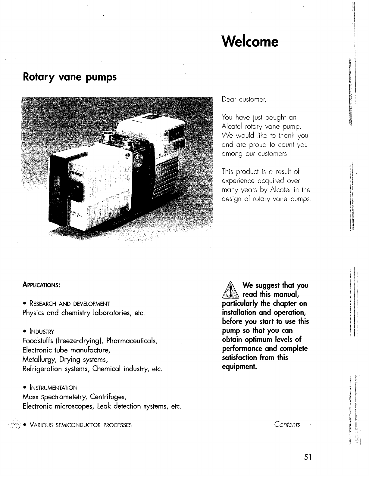
Rotary vane pumps
Welcome
Dear customer,
You
have
just
bought an
Alcatel rotary vane pump.
We
would like
and are proud
among our customers.
This
product
experience acquired over
many years
design
of
to
thank you
to
count you
is a result
by
Alcatel
rotary vane pumps.
of
in
the
'!
:1
'.
:1
i
ApPLICATIONS:
•
RESEARCH
Physics
•
INDUSTRY
Foodstuffs
Electronic
AND
DEVELOPMENT
and chemistry laboratories,
etc.
(freeze-dryingL Pharmaceuticals,
tube manufacture,
Metallurgy, Drying systems,
Refrigeration systems, Chemical industry,
•
INSTRUMENTATION
Mass spectrometetry, Centrifuges,
Electronic
•
VARIOUS
microscopes,
SEMICONDUCTOR
Leak
detection
PROCESSES
systems,
etc.
etc.
£
;.1:_t1i.,
particularly the chapter
installation and operation,
before you start
pump
obtain optimum levels of
performance and complete
satisfaction from
equipment.
We
sug.gest
read
so
that you
this
that you
manual,
to
use
can
this
on
this
Contents
51
Page 4

\
...
j
Page 5

Contents
The
PASCAL
series 5 to
21
m3/h
Presentation
Operating principle
a rotary vane pump
Technical characteristics
Pump
Accessories
Installation and connections
Safety instructions
Table
Filling with oil
Mechanical connections
Electrical connections
Motor
Operation
Precautions . . . . . . . . . . . .
Operating temperature
Before starting up
Start-up
Operation
Particular
Oxygen pumping
High pressure pumping and cycling
dimensions
of
protection . . . . . . . . . . . . . . . . . . . . . . .
of
the
product range
of
......................
.......................
..........................
......
recommended oils
........
....................
.....
the
pump
..........
of
gas ballast
uses
.....
.
.
...................
...................
.............
.
54
59
62
.63
.
.65
..
..
.72
.75
.75
.75
.76
.77
.79
.81
.82
56
67
68
69
71
Maintenance
Precautions
Troubleshooting and corrective actions
Maintenance frequency.
Draining the
Flushing
Change of type of oil
Replacement
Tools
Disassembling the pump
Cleaning components
Replacement
Reassembling the pump
Spare parts
and consumable products.
................
oil
the
pump
of
of
lists.
...
.
...
.
..
front shaft seal .
...
.
.....
all shaft seals.
....
.
..................
.
.
.
.83
.84
.87
.87
.88
.88
.89
.90
.
91
.94
.95
.96
149
.
53
Page 6

Presentation
of
the
product
range
A wide range
Specific solutions adapted
to
various
applications
SO
series
.
series
C 1
series
C2
series
Alcatel oil
applications.
They
(10-3 mbar), or
turbomolecular pump.
or
Standard pumps for several purposes (non-corrosive applications).
Manufacture of light bulbs, production of
tubes,
Pumps designed
seal
rotary vane
can
be
used
on
their own
in
pumping assemblies, e.g. at
metallurgy, centrifuges,
to
meet the requirements of analytical instrumentation and
pumps
are
used
in
all vacuum technology
to
achieve a maximum vacuum of 10.3 Torr
the
exhaust of a diffusion pump
TV
tubes,
manufacture of electronic
etc
.
R&D.
Mass spectrometer, electronic microscopes,
leak
detectors, sterilizers,
Pumps suited to the pumping
R&O,
laboratories, freeze-drying, pumping of
Pumps with increased resistance
aggressive processes
Ion
implantation, sputtering,
etc.
of
corrosive gases.
to
meet the requirements
of
the semiconductor industry.
etc.
GC/MS,
solvents,
LC/MS, gas analyzers,
etc.
of
the more
./
i
Hl
series
Sealed pumps offering maximum tightness.
Pumping
Nom.
I
SO
C1
C2
H 1
of pure or precious
flo
rate
series
series
series
series 2 stages
series
2
1 stage
2
1 stage 1005C1
2
2 stages 2005H1
3
m
/h
stages
stages
stages
gases.
5
20051 20101
1005S0
2005S0
2005C1
1010S0
2010S0
1010C1
2010C1
2010C2
10
15
20151 20211
1015S0 1021S0
2015S0 2021S0
1015C1
2015C1 2021C1
2015C2
2015H1
21
1021C1
2021C2
54
Page 7
Precautions
5
I,
to
21
SO,
m
C1,
3
/h
C2
rotary
Pascal
vane
series
pumps.
"'1
'I
]
Four 5 to
the
- A
very compact.
- An electrically insulated
handle
- An
the tightness of the pump during
accidental or voluntary shutdowns.
- A
of condensable vapours (except for
C2
The
phase
independently
pump, without the need to drain
the
On
-
glass
level easily when filling
during the operation of
- A
degas oil and dilute pumped gases
on
21
m3/h
pump
models
following main characteristics:
direct
drive
motor,
making
fold-away
is
used for easy carrying.
anti-suckback
gas
ballast
series).
universal three-phase or single-
motor
oil case.
the oil case, a
can be
neutral
C2
gas
series models.
system
enables the pumping
can be disassembled
of the
used
to
purge
rest
of the
vertical
inspect
the
the
is
used
ensures
sight
the
tank and
pump.
with
them
oil
to
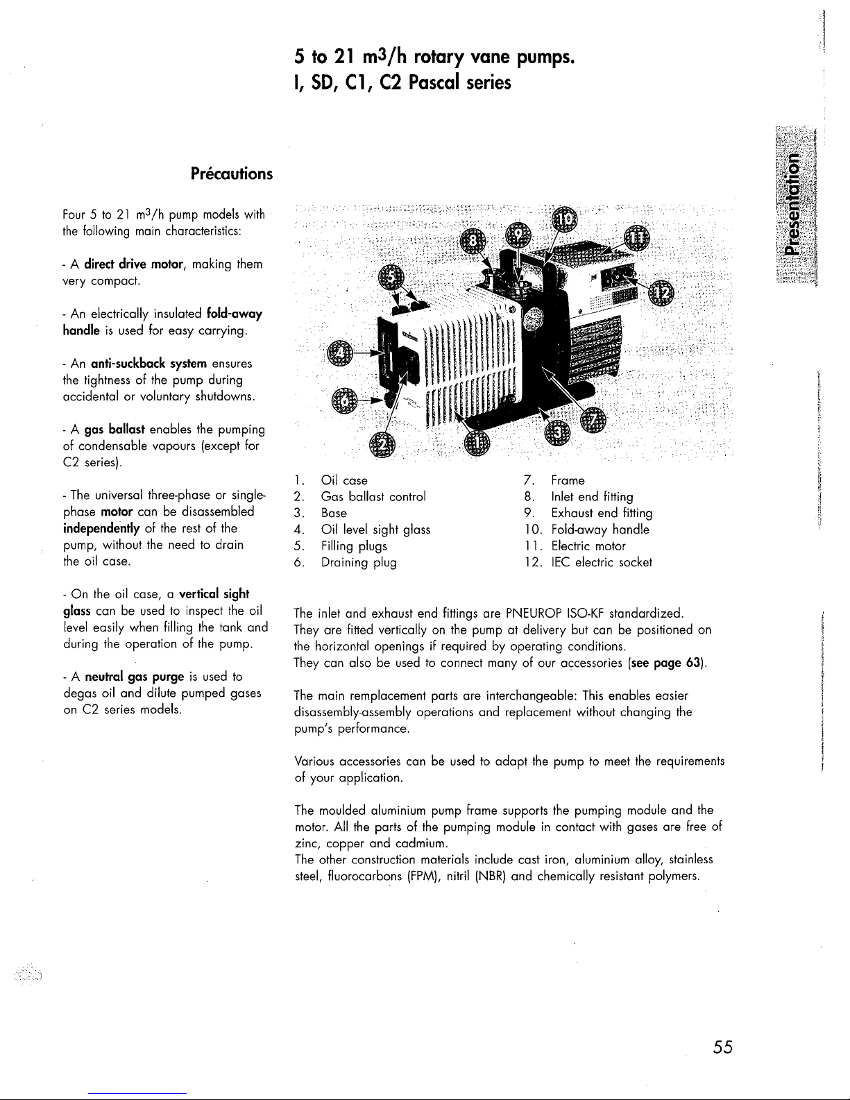
1.
Oil
case
2. Gas ballast control
Base
3.
4.
Oil
level sight glass 10. Fold-away handle
5.
Filling plugs 11. Electric motor
6. Draining plug 12.
The
inlet and exhaust end fittings are
They are fitted vertically on the pump at delivery but can be positioned on
if
the horizontal openings
They can also be
The
main remplacement parts are interchangeable:
disassembly-assembly operations and replacement without changing the
pump's performance.
used
required
to connect many of our accessories
7.
Frame
Inlet end fitting
8.
9.
Exhaust end fitting
IEC
electric socket
PNEUROP
by
operating conditions.
ISO-KF
standardized.
This
enables easier
(see
page
63).
used
to
adapt
the
Various accessories can be
of your application.
The
moulded aluminium pump frame supports the pumping module and
motor. All the parts of the pumping module
zinc, copper and cadmium.
The
other construction materials include cast iron, aluminium alloy, stainless
steel, fluorocarbons
(FPM),
nitril
(NBR)
and chemically resistant polymers.
pump to meet the requirements
in
contact with gases are free of
the
55
Page 8

Operating principle of
the
rotary vane pump
rotary
The
Single-stage
vane
pumping
given
pump
cycle
below:
Inlet
Transfer
This
is
a volumetric pump, with a functional
hollow
- A
- A rotor mounted eccentrically inside the stator for pumping.
- Two vanes
and springs.
cylindrical stator with inlet
sliding
in
the rotor, forced against the stator
part
and
exhaust valves.
is
As the vane passes in front
inlet orifice, an increasing space
formed into which the gas from the
chamber
When
the second vane passes, the
space
is
The gas trapped in the space
between the
to the exhaust orifice
rotates.
composed of:
by
centrifugal force
to
be evacuated expands.
closed.
two
vanes
is
as
the rotor
of
the
is
transferred
Compression
Exhaust
Application
56
In.
Single stage rotary vane pumps
1.0
above
condensable gases
Torr (1,3 mbar),
~Exh.
as
are
present.
The space communicates with the
is
exhaust, which
the gas
valve
The
casing when the pressure
to open the
are
the best choice for continuous pressures
well
as
applications where large amounts
is
gas
is
opened.
is
fitted with a valve:
compressed until the safety
expelled into the oil
valve.
is
sufficient
of
Page 9
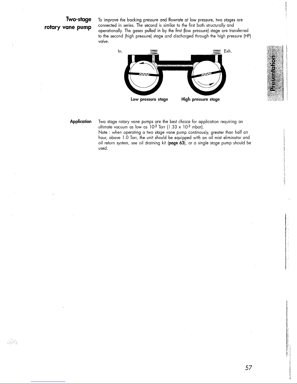
Two-stage
rotary vane pump
To
improve
connected
operationally.
to
the
valve.
in
second (high
In.
the
backing pressure and flowrate at low
series.
The
The
gases
pressure)
Low
second
pulled
pressure
is
similar
to
in
by
the
first (low
stage and discharged through
stage
pressure,
the
first both structurally and
High
pressure)
pressure
stage are transferred
the
stage
two
stages
high pressure
are
(HP)
Application
Two
stage rotary vane pumps are
ultimate vacuum
Note:
when operating a two stage vane pump continously, greater
hour,
above 1.0
oil return
used.
system,
as
low
as
Torr,
the
see
oil draining kit
unit should
10.3 Torr
the
best
choice for application requiring
(1.33 x 10.3 mbar).
be
equipped with
(page
63), or a single stage pump should
an
oil
mist
an
than
half
an
eliminator and
be
57
Page 10
Choosing
Its
the
function
right
oil
Oil
Oil
has
several important functions
-
It
lubricates mechanical components (bearings,
It
makes
It
-
Not
depends
dissolve gases.
Good pumping conditions are
The
- Expected pump performance.
Chemical aggression and corrosion
-
- Accessories
- Desired maintenance intervals and total operating
ALCATEL
moving parts relatively tight by limiting internal leakage.
carries away
all oils produce
choice depends on:
the
heat produced by
the
same
on
the
saturated vapour pressure of
used.
has
selected various
in
the
pump:
the
compressed
ultimate pressure
related
to
the
of
pumped gases.
types
of oil for
the
type
its
seals,
in
pumps
rotor, vanes, etc.).
gases.
a given pump. Ultimate pressure
oil,
its
of
oil
cost.
viscosity and
used.
(see
page
67).
its
ability
to
Lubrication
and
Gas
anti-noise
device
The
pump
is
equipped with a
required
the
in
the
vacuum pump.
lubrication oil and therefore
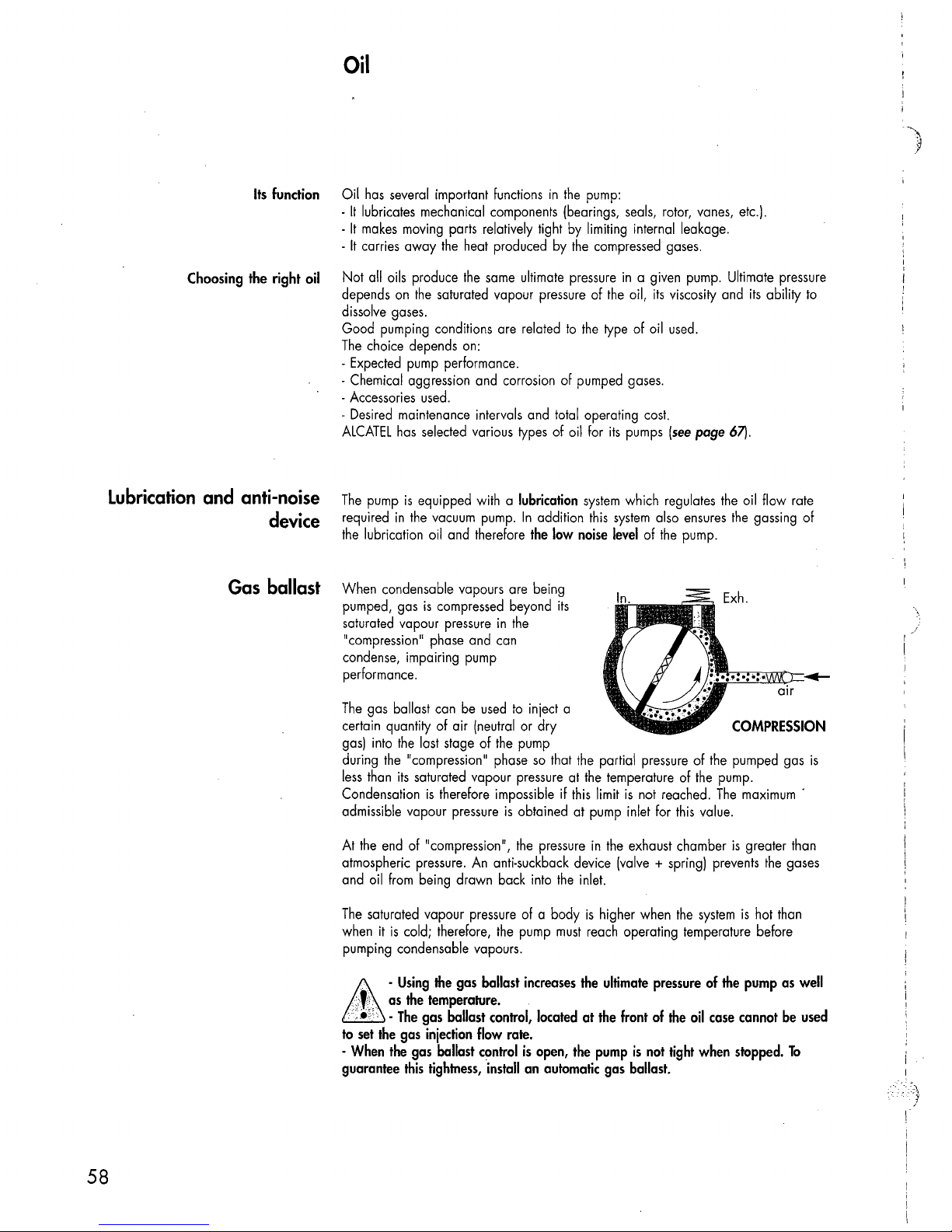
ballast When condensable vapours are being
is
pumped, gas
saturated vapour pressure
"compression" phase and can
condense, impairing pump
performance.
The
gas ballast can
certain quantity of air (neutral or dry
gas)
into
the
during
less
than
Condensation
admissible vapour pressure
At
the
end
atmospheric pressure.
and
oil
from
The
saturated vapour pressure of a body
when it
pumping condensable vapours.
compressed beyond
in
be
used
the
last stage of
"compression" phase
its
saturated vapour pressure at
is
therefore impossible if
of "compression",
being drawn back into
is
cold; therefore,
the
An
anti-suckback device (valve + spring) prevents
the
lubrication
In
the
the
to
inject a
pump
so
is
obtained at pump inlet for
the
pump
addition
low
its
that
this
pressure
the
must
system
which regulates
this
system
noise
level
the
partial pressure of
the
temperature of
limit
is
in
the
exhaust chamber
inlet.
is
higher when
reach operating temperature before
also
ensures
of
the
pump.
the
not reached.
this
value.
the
system
the
oil flow rate
the
gassing
COMPRESSION
the
pumped gas
pump.
The
maximum'
is
greater than
the
is
hot than
of
\
is
gases
58
'"
-
..
>,ci,
as
,;
, •.
'. -The
&
to
set
the
-
When
the
guarantee
Using
the
temperature.
gas
gas
injection
gas
this
tightness,
the
gas
ballast
ballast
ballast
control,
flow
rate.
control
install
increases
located
is
open,
an
automatic
the
at
the
ultimate
the
front
pump
gas
pressure
of
is
not
ballast.
the
tight
of
oil
when
the
case
pump
cannot
stopped.
as
be
To
well
used
Page 11
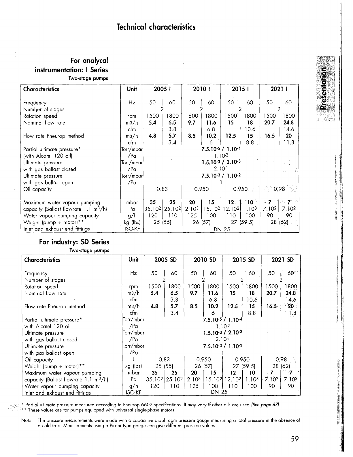
For
analycal
instrumentation: I Series
Two-stage pumps
Technical
characteristics
Characteristics
Frequency
Number of stages
Rotation speed
Nominal
Flow rate Pneurop method
Portia
(with Aleatel 120 oil)
Ultimate pressure
with gas
Ultimate pressure
with gas
Oil
Maximum water vapour pumping
capacity
Water vapour pumping capacity
Weight (pump
Inlet and exhaust end fittings
flow rate
I ultimate pressure *
ballast closed
ballast open
capacity
(Ballast flowrate
+
motor)**
For industry:
1.1
m3/h)
SO
Series
Two-stage pumps
Characteristics
Unit
Hz 50
2005 I
60 50 I 60
I
2010 I
2 2
rpm
m3/h
cfm
m3/h
cfm 3.4 6
Torr/mbor
/Pa
Torr/mbor
/Pa
Torr/mbor
/Pa
mbor
g/h
kg
ISO-KF
Unit
1500 1800 1500 1800 1500 1800
5.4
6.5
9.7
3.8
4.8 5.7
I 0.83 0.950
35
Po
35.102 25.102 2.103 15.102 12.102 1.10
25
8.5
20
120 110 125 100 110 100
25
(Ibs)
(55)
2005
SO
26
2010
2015 I
50
11.6
15
6.8
5
1.10-
/
12.5
1.1
2
10.2
7.5.10-
1.5.10-3/ 2.10.
1
2.10-
7.5.10-3/
1.10-
1
DN
12
27 (59.5)
25
15
(57)
SO
1
2
4
0-
3
2
0.950
2015
60
18
10.6
15
8.8
10
SO
2021
50
1500 1800
20.7
16.5
7
3
7.10
90 90
28
2021
1
2
0:9$
2
(62)
I
60
24.8
14.6
20
11.8
.7
7.10
SO
i
, ,
'.
~l
:
'.
I
2
Frequency
Number of stages
Rotation speed
Nominal flow rate
Flow rate Pneurop method
Portial ultimate pressure*
with
Alcatel 120 oil
Ultimate pressure
with gas
Ultimate pressure
with gas
Oil
Weight (pump
Maximum water vapour pumping
capacity (Ballast flowrate
Water vapour pumping capacity
Inlet and exhaust end fittinqs
:'
..
• Partial ultimate pressure measured according
••
These values are for pumps equipped with universal single-phase motors.
Note: The pressure measurements were made with a capacitive
ballast closed
ballast open
capacity
+
motor)**
1.1
m3 fh)
a cold trap. Measurements using a Pirani type
Hz
rpm
m3/h
cfm
m3fh
cfm
Torr/mbor
fPa
Torr/mbor
fPa
Torr/mbor
/Pa
kg
mbor
Po
g/h
ISO-KF
to
Pneurop
I
(Ibs)
6602
gauge
50
60 50
1
60 50 1 60
1
2 2 2
1500 1800 1500 1800 1500 1800
5.4
6.5
9.7
11.6
15
18
3.8 6.8 10.6
4.8 5.7
8.5
10.2 12.5
15
3.4 6 8.8
/
1.10-
2
/ 2.10-
1
1.10-
4
3
2
5
7.5.10-
1.10-
1.5.10-3
2.10-
7.5.10-3/
1
0.83
25
(55)
35
25
35.102 25.102 2.103 15.10
120 110 125
specifications.
diaphragm
can give different pressure values.
pressure
0.950 0.950
26
(57)
20
15
2
100 110 100
DN
It
may
vary
if
other oils are used
gauge
measuring a total pressure
27 (59.5)
12
12.102 1.10
25
10
(See
3
1500
7.10
page
in
50
.1
2
1aOO
20.7
24.8
14.6
16.5'
-20
11.8
0.98
28
(62)
7
2
7.10
90 90
67) .
the absence
60
7
2
of
59
Page 12
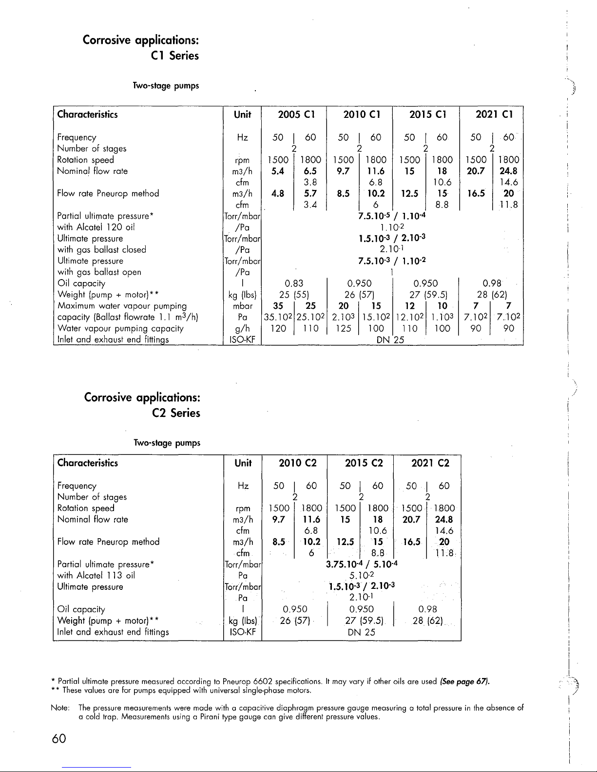
Corrosive
applications:
C1
Series
Two-stage
pumps
Characteristics
Frequency
Number of stages
Rotation speed
Nominal flow rate
Flow rate Pneurop method
Partial ultimate pressure *
with
Alcatel 1 20 oil
Ultimate pressure
with gas ballast closed
Ultimate pressure
with gas ballast open
Oil
capacity
Weight (pump + motor) * *
Maximum water vapour pumping
1.1
capacity (Ballast flowrate
Water vapour pumping capacity
Inlet and exhaust end
fittin~s
m3/h)
Unit
Hz
rpm
m3/h
cfm
m3/h
cfm
Torr/mbar
/Pa
Torr/mbar
/Pa
Torr/mbar
/Pa
I
kg
(Ibs)
mbar
Pa
g/h
ISO-KF
2005
50
I
2
1500
5.4 6.5
4.8
0.83
25
(55)
35
2
35.10
120
C1
60
1800
3.8
5.7
3.4
25
25.10
110
2010
C1
I
60
50
2 2
9.7
1800
11.6
1500
6.8 10.6
8.5
10.2
6
7.5.10-
1.5.10-3 / 2.10-
2.10-
7.5.10-3 / 1.10-
0.950 0.950
26
(57)
2
20
2.10
3
15.10
15 12
125 100
DN
2015
50
1500
15
12.5
5
1.10-
/
2
1.10-
1
1
27
2
12.102 1.10
110 100
25
I
1800
8.8
4
3
2
(59.5)
C1
60
18
15
10
2021
50 I 60
1500 1800
20.7 24.8
16.5 20
0.98
28
7
3
7.10
90
2
2
(62)
C1
14.6
11.8
7
7010
90
2
Corrosive
applications:
C2
Series
Two-stage
pumps
Characteristics
Frequency
of
Number
Rotation speed
Nominal flow rate
Flow rate Pneurop method
Partial ultimate pressure *
with
Ultimate pressure
Oil
capacity
Weight (pump
Inlet and exhaust end fittings
* Partial ultimate pressure measured according
**
These
Note:
stages
Alcatel 113 oil
+
motor)**
values are for pumps equipped with universal single-phase motors.
The
pressure measurements were made with a capacitive
a cold trap. Measurements using a Pirani type
m3/h
m3/h
Torr/mbar
Torr/mbar
kg
ISO-KF
to
Pneurop
Unit
Hz
2010
C2
50 I 60
2
rpm
cfm
cfm
Pa
Pa
gauge
1500 1800
9.7 11.6
6.8
8.5 10.2
6
I
(Ibs)
6602
0.950
26(57)
specifications.
diaphragm
can give different pressure values.
2015
50
1500 1800
15
12.5
3.75.10-
5.10.
1.5.10-3 / 2.10-
2.10-
0.950
27
I
DN
It
may
vary
pressure
gauge
I
2
C2
60
2021
50 I 60
2
1500 1800
18
20.7 24.8
10.6
15
16.5 20
8.8
4
(59.5)
/
5.10-
2
1
4
3
0.98
I
28
(62)
25
if other oils are used
measuring a total pressure
C2
14.6
11.8
(See
page 67).
in
the absence
of
..
!
I
i
I
.!
..
~'i.
)
I
60
Page 13

For
industry:
Single-stage pumps
SO
Series
Characteristics
Precautions
Frequency
Number
Rotation speed rpm
Nominal flow rate
Flow rate Pneurop method
Ultimate' pres'sure*
with gas ballast closed
Ultimate pressure'"
.yvith
Oil
WE~ight
Maximum water vapour pumping
capacity (Ballast flowrate
Water
Inlet and exhaust end fittings
of
stages
gas, balla,st open
capacity
(pump.+.
vapour
niofor)**
pumping
.
1.1
m3/h)
capaCity
Unit
Hz
m3/h
cfm
m3/h
cfm
Torr/mbar
/Pa
Torr/mbar
/Pa
kg
mbar
Pa
g/h
ISO-KF
Corrosive applications:
C1
Series
1005
SO
50
60
I I
1
5.4
1800
6.5
1500
1010
50
1
1500 1800 1500 1800
9.7
3.8
5.5
4.8
'
8.5
3.2 5.8
3.75.10-
3/4
2
4.10
30
21
1.1
(46)
25
I
(Ibs)
3.103 25.102 4.103 35.102 35.10
120
130"
22
40
260
1.0
(48)
SO
60
11.6
6.8
10
12.5
2
/
5
35 35
280
DN 25 ISO
330 370
1015
SO
50 I 60
1
15
18
10.6 14.6
15
8.8
2
5.10-
5.25/7
7.10
1.0 1.0
24.5
(54)
30
2
KF
3.10
3
1021
50 I 60
1
1500
20.7
16.5
2
25
(55)
25
2
25.10
340
SO
1800
24.8
20
11.8
22
22.10
340
2
Single-stage pumps
Characteristics
l,i~qiiehcy
Number
'R9ia.ti9~,
Nominal flow rate
FI9f
'Uiti~~t~'pr~s~~re
with gas ballast closed
'Uiti
Witbgos,
Oil
.:\§iejghUp~hlp~
Maximum water vapour pumping
capacity (Ballast flowrate
\Y:{9:t~~~9FiR1~(p~mpihgcOpacHy,
Inlet and exhaust end fittings
*
Pressure
**
Note:
of
~tages
~pe~9
rati!'
PneQtop,'
n1ate'prd~sure
pqllast.,open
capacity
measured according
These
values are for pumps equipped with universal single-phase motors.
The
pressure measurements were made with a capacitive diaphragm pressure gauge measuring a total pressure
a cold trap. Measurements using a Pirani type gauge can give different pressure values.
:,;
*
}:,mot
method
cir
)
**
1.1
to
Pneurop
m3/h)
.•
,
,
..
' "
,.
6602
Unit
Hz
rpm
m3/h
cfm
m3/h,.
cfm
Torr/mbar
/Pa
Torr/mbar
/Pa
I
kg
(Ibs)
mbar
Pa
g/h
ISO-KF
specifications with Alcatel
1005 Cl
50
I
60
1
1500 1800
5.4
6.5
3.8
4.8
5.5
3.2 5.8 8.8
1.1
21(46)
30
3.10
120
25
3
25.102 4.103 35.102 35.10
'130'
120
·1500
3/4
4.10
oil charge.
1010
50'
9.7
8.5
2
1.0 1.0
.22(48)
40
260
Cl 1015 Cl
I'
60
50
1
iSOO
11.6
1500 1800
15
6.8
.10
3.75.10-
12.5
2
/
5.10-
5
'24.5
DN
, .
25
..
330
35
if
other oils are
35
280
It
may vary
2
1
1
2
'{54)
3.10
60
18
10.6
15
5.25/7
7.10
30
3
370
1021 Cl
50 I 60
1
1500
1800
20.7 24.8
14.6
16.5
2
25
25.102 22.10
,340
used
in
20
11.8
1.0
5
Z5(5
J'
22
'340
(See
page
the absence
.'
,",-,
2
67).
of
61
Page 14

Pump
dimensions
Filling
3/8G
!
\
Inlet
C2
Bubbler
A
63
45
192 96,5
Series
DN25
ISO
\
1\
KF
113,5
37
I Exhaust
DN25
915
ISO
KF
/
37/
. ',..;
,\t
r,-
£
1/
If wei
\
ir
[I-
II")
~
\
-r--=-
N
~
~~
r-
\
95,5
226
259
B
~
237
1\
II")
2:
0
'<t
c:;
N
N
II")
'<t'
~.
~
-I
-
-
\
I I
1r'
-
1
c=J
1
ffi
101
98
J
141
164
-
~~
-0
c:;
0
:=
\
:\
)"
!
Drain
3/8
G
Dim.
inch/(mm)
A
B
C
62
1005
4.55
(115.5)15.4
1
1010
9
(229)
(183)
7
(136.5)
2005 1015
1
14.55
(115.5)
\ 4 x 8
Pump
6.2
(157.5)
mm
9.8
(249)
8 (204)
diam. holes
type
2010
1
15.4
(136.5)
1021
7.03 (178.5)16.2
10.6
8.9
1
(270)
(225)
2015
(157.5)
2021
11.5 (291)
9.7 (246)
7.03
(178.5)
.~
J
Page 15
OME
Oil
mist
eliminator
25 S/OME
25
CH
OME
OME
25
5 104200
25
CH
Accessories
066849
Exhaust
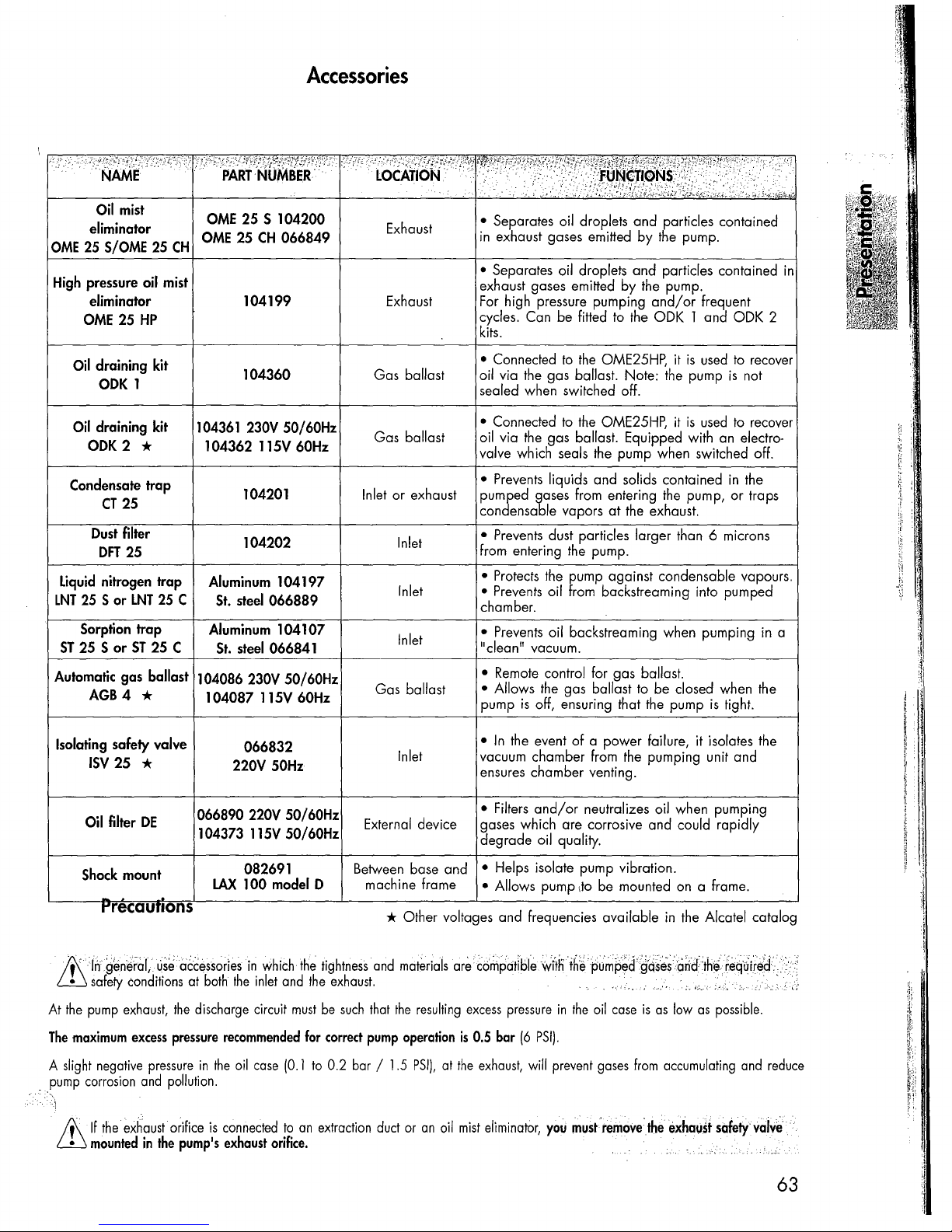
• Separates oil droplets and particles contained
in
exhaust gases emitted
by
the
pump.
High pressure oil mist
eliminator
OME
25
HP
Oil draining
OOK
Oil draining
OOK
Condensate trap
CT
Dust filter
OFT
Liquid nitrogen trap
LNT
25 S
Sorption trap
51
25 5
Automatic gas ballast 104086 230V SO/60Hz
AGB 4 *
2 *
25
25
or
or
1
LNT
ST
kit
kit
25 C
25 C
104199
104360
104361 230V 50/60Hz
104362 115V 60Hz
104201
104202
Aluminum
St.
Aluminum
St.
104087
steel
steel
104197
066889
104107
066841
11SV
60Hz
Exhaust
Gas ballast
Gas ballast
Inlet or exhaust
Inlet
Inlet
Inlet
Gas ballast
• Separates oil droplets and particles contained
exhaust gases emitted by
For
high pressure pumping
Can be fitted to
cycles.
kits.
• Connected
oil via
sealed when switched off.
• Connected
oil via
valve which seals
•
Prevents
pumped gases from entering
condensable vapors
•
Prevents
from entering
•
Protects
•
Prevents
chamber.
•
Prevents
"clean" vacuum.
•
Remote
• Allows
pump
to
the
the
is
the
gas ballast. Note:
to
the
gas ballast. Equipped with
the
oil from backstreaming into pumped
control for gas ballast.
the
off, ensuring that
the
liquids and solids contained
dust particles larger than 6 microns
the
pump.
pump against condensable vapours.
oil backstreaming when pumping in a
gas ballast to be closed when
the
pump.
and/or
the
ODK 1 and ODK 2
OME25HP, it
OME25HP, it
pump when switched off.
at
the
exhaust.
the
the
the
pump
frequent
is
used
pump
is
used
pump,
is
is
an
in
or
tight.
to
recover
not
to
recover
electro-
the
traps
the
in
Isolating
safety valve
ISV
25
*
Oil filter
Shock mount
DE
066832
220V
066890 220V 50/60Hz
104373 115V 50/60Hz
082691
LAX
100 model 0
t"recaunons
!f\rngen~rar,
ill
safety
At
the
pump
The
maximum
A
slight
negative
pump
corrosion
i
If\
If
the
ill
mounted
.U.S~
conditions
exhaust,
excess
exhaustorifice
a~cessorles
at
the
pressure
pressure
and
pollution.
in
the
pump's
in.
both
discharge circuit
in
the
is
which
the
Inlet
recommended
oil
case
connected
exhaust
•
In
the
event
of
a power failure, it isolates the
neutralizes oil when pumping
be
50Hz
Inlet
External device
Between base and
machine frame
vacuum chamber from
ensures chamber venting.
• Filters
gases which are corrosive and could rapidly
degrade oil quality.
• Helps isolate pump vibration.
• Allows pump Ito
and/or
* Other voltages and frequencies available
the
tightness
and
the
must
be
for
correct
(0.1
to
to
an
extraction
orifice. ,
exhaust.
such
that
pump
0.2 bar /
and
duct
materials
the
resulting
operation
1.5
PSI),
or
an
are
C6n,pcitiblewftfiih~pumpe.d'.gQs.
excess
pressure
is
at
oil
0.5 bar
the
mist
(6
exhaust,
eliminator,
will
". . ""
in
the
PSI).
prevent
you
must'remove:the
oil
gases
the
pumping unit and
mounted
on
In
e~Cind.
;"
case
is
as
low
from
accumulating
exha\Jst
,'.
,.'
a frame.
the
Alcatel catalog
:th.e
.• · .....
feq
..
>.
as
possible.
lii;ed."
'..
and
"
reduce
. c,
'0.,
safetyvalv~
d
•• ' ,.
",i,
63
Page 16

I
I
I
'")
)
I
\
)
64
.-.
i
:\
1
I
)
Page 17
Safety instructions concerning the installation and
Unpacking
Storage
operation
When
you receive the equipment, unpack it carefully. Do not discard the
packaging
during transport. Otherwise, take the necessary measures with the transporting
company and,
For all handling, only
handle, etc.).
The
pump
bottles. Similarly, it
of
pumping
until you have ensured that the pump
if
necessary, notify
use
the devices provided for this purpose (lifting rings,
is
not supplied filled with oil.
is
recommended to drain the pump before redispatching
systems
ALCATEL.
The
oil
has
not been damaged
is
contained
in
separate
the equipment.
• if the pump
without
temperature between 41°F and 149°F or 5 and
is
to be stored,
particular storage precautions for up to 3 months (ambient
we
guarantee the reliability of our equipment
6SOC).
•
For
storage periods
oil during storage.
orifice blocked) for approximately 1 hour in order to lubricate all
the functional block (see
Then,
stop
the
pump and store it with the inlet and exhaust orifices sealed:
clamping ring, centring ring, plug, etc.
The
shaft should be rotated
following this storage procedure.
• After 6 months storage without oil, factors
humidity,
particularly
and the gumming
particularly oil leaks. Before any start-up (new pump
pump
Note
The
light (sunlight and ultraviolet light)
hardening (AFNOR standard
salt air, etc. may cause the deterioration
the
must
be disassembled (see
1:
seal
kits
must
of
over 3 months,
For
this, fill the pump and
page
76).
by
hand or
hardening
of
be stored with caution. Keep
of
O-rings and the "sticking"
oil.
in
this state, a pump may have operational problems,
FD T 46.022).
by
page
91), and all the
in
order
we
recommend to fill the pump with
run
it at ultimate vacuum (inlet
starting the pump every six months
such
as
temperature, degree of
of
the pump components,
of
lip seals on shafts
as
well
as
seals
changed.
them
away
from heat and
to
prevent the elostomers from
the
parts
used), the
of
65
Page 18

Installation and
start-up
•
The
machines
with decree
electrical codes that apply.
•
It
is
important to isolate the machine from the power source before any
intervention on
• When switching off the power of equipment containing capacitors loaded
with over
pins (single-phase motors, equipment with mains filter, frequency converter,
monitor, etc.).
88-1056
60
VDC or
must
be connected to an electrical installation
dated 14th November
the
equipment (for maintenance purposes).
25
VAC, take precautions when accessing the connector
1988,
in
as
well as any local
compliance
,
')
j
• Vane roughing pumps
information from the manufacturer on
product used.
•
Our
pumps are tested
for the USA (Alcatel
same oil during operation.
If
changing the type of oil, refer
of
and the type
•
Our
pumps are designed to prevent any thermal risk for user safety.
However, specific operating conditions may generate temperatures which may
justify particular attention on the part of the user (outer
lubricant required.
use
lubricants, it
in
the factory with
113
oil for the C2series).
to
the
is
recommended to request
the
safety data
ALCATEL
chapter concerned for the procedure
sheets
120
oil or Alcatel
It
is
recommended to
surfaces>
concerning the
use
70°e).
119
the
66
Page 19

Vapor
Assembly
pumping
(continued)
procedure
-
we
do not recommend an oil mist
eliminator when pumping condensable
vapors:
it
it outside the condensation zone.
- remove the stop
exhaust;
mechanical device creating a negative
pressure from
- Valve off the pump from the
30
- Start pumping and check
- After pumping, regenerate the oil using gas ballast if it
discoloured.
- Change the
improved
if
it
is
essential,
directly to the pump exhaust but place
if
possible, connect the exhaust
0.1
minutes with gas ballast
the
level drops, oil
•
the
level rises, condensates have been added to the oil.
•
•
if
the level
oil
by
regeneration.
do
not connect
valve from the pump
to
to
0.2
bar.
system
(see
page
the
oil level:
is
being lost;
is
too high, change
as
soon
as
inlet pressure characteristics
a
and increase the pump temperature,
76).
In.
the
oil and regenerate.
is
cloudy
drop
Exh. •
Condensate
trap
or
and are not
78
Page 20

Operation of gas ballast
Regeneration
Pumping
Choice
of
pump
condensable
vapours
pump
and
system
of
In
a pump stored with the same oil for a long time, condensed vapours may
contaminate the oil bath and affect performance.
oil
pumping vapours and when
sight glass.
-
Run
the
pump, shutting it off from the
plug.
- Open the gas ballast and
1 hour, or longer
temperature rise
the oil bath.
To
pump with condensable products, it
pump. For this,
1/2
hour with the gas ballast open, or 1 hour (if possible) with the gas
ballast closed. When the oil bath
the pump
The
the pump temperature and the quantity
Thus,
suitable. However, when not pumping vapours,
Care
admissible water vapor pressure with the pumped product.
by
The
of
vapours are
cause the products condensed
is
pump's capacity to eliminate condensable vapours
for high vapour levels
should be taken
reading the pump characteristic table for water vapour.
use
of
if
the oil remains cloudy.
of
the pump while eliminating residual va pours present
isolate the pump from the
reduced
cold traps or condensers are recommended when large quantities
to
be extracted. Excessively intense or prolonged pumping may
the
oil appears cloudy or discolored through the
allow
the pump
is
hot, the condensation
or
prevented.
in a system,
to
limit the inlet pressure
in
the trap to be evaporated a second time.
system
is
necessary to operate with a hot
system
of
air
the single-stage pump
This
is
also the case after
at the inlet
to
operate for
This
operation accelerates the
and
introduced
its
of
the pump to
by
a valve or a
1/2
allow
it
of
vapours
is
related
by
the gas ballast.
ultimate pressure
This
hour
to
to
operate for
to
their type,
is
more
is
its
maximum
is
obtained
in
in
higher.
Choice
Assembly
of
oil
Choose an
be condensed
etc.)
The
- the pump and
- the pressure at the exhaust
as possible (removal of the oil mist
eliminator ...
- the condensates are collected
separately from the oil bath and
block
For this:
- avoid using any
promotes the condensation
and the return of
pump.
-
use
oil which facilitates
in
the
oil bath (anti-emulsion oil for water-based compounds,
(see
page 67).
condensation
the
exhaust duct.
a condensate collector;
of
vapours at the pump exhaust
oil temperature are high;
);
vertical ducting which
these
the
is
as
of
products
products to
separation
low
do
not
the
of
pumped products which may
is
reduced if:
•
Exh.
77
Page 21
Start-up
• When using a three phase motor,
(see
motor.
electrical connections start-up
check
the direction of rotation of the
chap.
page 71).
• Check the oil level
• Start-up the pump.
• Allow the pump
vacuum:
During this operation, make sure that the oil circuit
of
the oil fill plugs to listen
At
start-up, the oil enters the lubrication circuit
result, noises
as
the oil heats up.
has been replaced.
Under normal temperature conditions, the oil circuit should start
1 minute after start-up
of
contamination).
•
Using
- to decontaminate the pump's oil;
- to accelerate heating.
through the oil sight glass) when the pump
starting
sure). If necessary, stop the pump and adjust the oil level between the
and"
min" levels on the sight glass.
will be heard (first irregularly, then regularly) which .will reduce
the gas ballast:
of
the oil circuit and the operating conditions
(See
page 68).
to
run for one hour with the inlet blocked
is
to
the pump.
of
the vacuum pump.
These
noises will no longer be heard when the fill plug
(this
time may
It
is
normal for the oil level to change
vary
with the type
is
hot, due to expansion
at
ultimate
operating. Remove one
less
of
oil and
of
the pump (inlet pres-
(as
its
can be
As
a
than
degree
of
the oil,
"max"
seen
, I
I
I
In
the event
actions" table
of
a malfunction, refer
(page 84).
to
the "Troubleshooting and corrective
76
Page 22

Operation
Preliminary precautions
Operating
temperature
•
The
be
use.
•
The
vacuum
dangerous.
•
The
pumps
However,
performance
guaranteed
pump
Study
the
are
designed
specific
operating
and
if it
is
is
also a compressor:
user
manual
to
may justify partic"laraftention:
•
Product
product
of
pumps).
Be
sure
-
At
temperature
-
The
(12°C)
- Under
case)
operating conditions).
tightness
leaves
the
tightness
start-up,
particularly when
to
fill
the
before switching
is
greater than 53°F
ambient
will
operating
and 113°F (45°C).
these
conditions,
be
between 140°F and 158°F (60 and
is
gu(jfant~d
factory.
pump
It
with
temperature
the
operating
operated
before
prevent
conditions
on
the
for
is
the
users
pumping
oil
(see
page
on
the
(12°q.
for the pump
stabilized
safety
of
this
prod~ctcan
according
tonornl'al.i:onditiorisof
incorrectoperatio~
any
may·
part
skirting
thermal
generate
of
the
user>
up
the pump.
risk
for
IJser
. temperatures
lqoC)..
normciloperatin9>conditions~hen)he
responsibilitY
dangerous.
to
maintairi:theleY~I
produds(onCseries
may
safety.
only
be.
which
...
..
...
68).
motor, check that the oil bath
must
be between 53°F
pump
temperature
700q (depending on
(at
the
front of
the
oil
Before starting-up
the pump
Special
Synthetic oils are much more viscous when cold than mineral oils.
Do not start up
For
drops of oil
In
with slightly contaminated oil,
the oil
internal thermal protection
pages
case -Synthetic
the
the
same
reason and
(I
to 2
&
Check
that
certain cases, when the pump
in
the
pump
72
& 73).
oils
pump at ambient temperatures below 59°F
to
3
)
cm
through
the
exhciust
is
heated up.
to
(1
facilitate lubrication
the
inlet orifice before starting.
orifice
is
not blocked.
is
started up
the
current after start-up may remain high until
These
conditions are sufficient for
be activated, making start-up impossible
of
the pump, pour a few
in
cold ambient conditions, or
YC).
the
(see
75
Page 23

Incidents
The
vacuum pump does not
produce a vacuum (continued)
Causes
Corrective
actions
Noisy pump
Pump too hot
•
At
the pump exhaust, the
installation produces an exhaust
pressure of
-.-Oil
[~
r---~--~.~,_----_._.-------
-.-Incc)rrect
mi;t eliminator cartridge
clogged.
• Oil
level
-.
OXcont~;;inateJlPr~senc;-;r---
particles) .
•
Pump
used.
~~~;C6~~~~~:s~;~g~~*pl.t~--
• Motor coupling incorrectly set or
damaged.
• Incorrect
assembly
• Vanes
1,1
25
Torr
(1.5
too high.
not
p;~pared
-----------~-~
fan
anti-suckbactdeviCe-
---.,----c-------
damaged
for
assembly.
or stuck.
the
bar).
oil
Check the installation.
~
...
:--!
--"'j
i
!
I
1
1-;::--......,.-------------------------------1
--
Replace.
Drain
and
fill
with
-D~~-i·n:-1T~-s·h--~~-(r·~-e1i
oil. j
Check the
the type of oil.
Check
-R;pla~;-ihe--~-otor-cjjter-in-;-pectiori
Check
Check
-Repeat the-Ci-ssem5ry.------------_·--!
pump
the--power
the
-setting.
theassembly.------------j
a new oil.
n-~ith-~
configuration or .
-SUpply.
r~~
--------1
--------------.-j
i
R;;pi~~-------'====-J
• Ambient temperature too high.
--
•
Pump
ventilated place or vents
blocked.
•
Operation at high pressure
P >
-
-~--oiT~ont~;;T
-;~p
--_._---_._----_
22
• Excess pressure at exhaust.
• Motor
Motor
-not prepared
used or
.
placed
In
Torr
(30 mbar).
i~
over-voltage or
in
short-circuit.
nated-.----------
oil
unsuitable.
..
a poorly
for
__
...
_--
Check the installation_
------.---~---
Check
------
-----
the
Oi-I~I
--
Check the
~-k
~~tor·----------------------I
Drain,
oil.
Check pump configuration or type I
of oil. I
------_.---------------_.
._---_.
for
system leaks.
exh~~st-line;~---------I
the-voltage,
flush
and
replace--~i
refill
------~
i
j
I
I
with
clean !
______
__
._-
______
.-1
1
85
Page 24

\
Incidents
Considerable
Poor
pump
off.
___
Oil
in
oil
losses.
tightness
.
_______
base. I •
when
switched
.
________________
I
I
Causes"······
Drain
and
fill
with
new
•
0;1
le'el
tao
h;gh.
• Operation at
-.-GasbaTlastopen:··-
1 - accidentally,
2 - pumping
___
vapours.
•
Leak
at
seal.
~~~
l-·
Safety va!:,!_
high
p~:_~~~r~.
of
condensable
oil
case seal or at
open~______
da~_<:J.ged.
I~~~;:~;~;;;~,kb:~::em~~_
..
___
1
::_;r_I;_o~~;~~~c_._-_-_--._.··
-.
Oil
case and frame cleaned I
poorly during reassembly.
;.
-OiT.
case--seaTPi~~hecr-
-;F~onTseaida-maged---orfelt
saturated.
-----------------_._--.------
- -
J
Use
an
HP
type
__
_
___
front
with
oil
e-------.---.-.-.-
1 - Close.
2 .
._
~-----.~~-~------
Check the assembly and replace
the seals
S-Relopslaec·-
recovery.
..
----------------
Use
a condensate collector.
-e-.--------------=l
f::~:~e
oil
if
necessary.
a"embly.
·~;~:~~"~a~;~;;I;,;h~~O;1
--1--+------------------··---·----1
~'
..... ----.-.
---
-.---
Remove
I I
-Disassemble the
I
faces and
l~~~~~:~-~~~
the
base and clean. !
refit
a new seal.
__
~=~~~~_-_
oil.
mist
eliminator
___~
oil
case, clean -the
..
---.-
...
-----
:==-~
-
I
_I
~~
j
I
I
86
I
.1
.,
)'
Page 25

Maintenance frequency
Maintenance
An
incorrect ultimate vacuum or a reduction in pumping
oil
has
deteriorated.
The
periodic inspection of
a
sample
of new oil
the
lubricant.
of
The
frequency at which oil
the
oil
is
the
cloudy,
The
the
pump
oil
- if
pumping.
- a thickening of
indicate that
Drain
can
the
oil
and
the
state
of
the
oil
is
in
order
to
check
the
level
is
renewed
this
indicates that condensables
be
regenerated
oil, together with a blackish color and a "burnt"
has
deteriorated.
flush
it.
is
adapted
using
the
speed
are
signs
that
the
performed by comparison with
of contamination or deterioration
to
the
type of operation:
have
been
absorbed during
gas
ballast
(see
page
77].
smell
I
i
I!
I
!
,
,
i
I
!
!.
,
~
j
i
Draining
Normally, for a pump operating continuously at a pressure lower than 0.75
(1
mbar) with a
This
value
vacuum
Similarly,
changed at intervals of 6 months to a maximum
sticky).
Note:
intervals adapted
page
required
Every
63)
/'\
•
.Thedraj~in~ope~ation
mcomr1umcatioi1.'wlth,t~"r
ensur~
perst>;ral,
The
pump
atmospheric
-
switch
off
isolate
-
installation;
- tilt
the
- unscrew
the
oil
case
of
the
oil
When all
two
plugs
for about 10
Take
open.
may
appear at
removes
- drain
this
plug;
- replace
of
the
oil
clean
is
given
as
is
sufficient (for primary
if
the
pump
pumping operation
to
each
can
reduce
safety.
must
be
drained
pressure.
the
pump;
the
pump
or disconnect
pump;
the
draining
and
the
filling
case.
the
oil
has
temporarily and
seconds
care with
the
exhaust.
the
oil
from
oil
by
removing
the
draining
case
oil sight
gas (dry air),
a guide only.
is
stopped frequently for long periods,
specific application.
the
frequency of
the
oil should
It
may
vacuum
is
different.
these
plac~s;
~e
.con~~in~ted,
be
be
extended
pumps).
of
This
oil
The
use
maintenance operations.
1 year
must
oli~ldeah,nosphere,~Takealll')ecessc;lry,
:':
.'
.,"
;.
'.
; , ' ,
when
hot
and
after
the
oil
For
this:
from
the
plug
on
the
side of
plug
on
the
top
drained, replace
run
leaving
the
the
the
oil
mist
This
functional block;
the
plug
and fill with
glass
through
the
pump
intake
which
operation
draining
the
fresh
the
filling orifice
oil
to
the
changed every 6
to
1 year if
the
(oil
therefore
of certain
pumping, circuit in,
",
case
has
appropriate
(see
page
the
oil should
may
become
be
accessories
. • : .
been
:.:'".
maximum
69).
months.
ultimate
changed at
steRs.
vented
be
.','
Torr
(see
,
to,
to
87
Page 26

Flushing
The
draining operation
particularly dirty.
the
pump.
can
be
followed by a flushing operation if the oil
This
operation requires a volume of oil equal to
the
capacity of
is
Change
Compatible
Incompatible
of
type
of
oil
oils
oils
After draining
intake filter, clean it and replace it.
the
flushing oil very slowly through
develop at
may
draining plug. Replace
ALCATEL 5 to
120
oil or Alcatel 119 for
specified otherwise
quantity of
Thus,
if
Mineral oil
pump
(see
Mineral oils are also compatible with mineral-based synthetic oils
(see
page 67).
This
is
(e.g.
ALCATEL
Synthetic oils are considered
reasons:
resulting mixture, which could
contamination or deterioration.
For
the
are
also expensive, are treated
the
oil
case
(see
page 87), replace
Run
the
the
exhaust.
21
m3/h
in
oil remains
you wish
the
they are expensive. A mixture may
same
to
use
can
be
replaced by another type
above)
case
using
when, for example, a mineral oil
120
by
reasons,
Stop
the
pump and drain
the
plug and fill with
series
pumps
are
USA
(ALCATEL
the
order. When
in
the
functional block
another type of oil, proceed
the
new oil and fill
ALCATEL
clear synthetic and mineral oils
113).
to
be
incompatible with each other for practical
be
interpreted mistakenly
as
synthetic oils.
the
draining plug.
the
pump at atmospheric pressure, pour
inlet orifice.
tested
113 for C2
the
Take
care with oil
the
fresh
oil
(see
in
the
factory with
series
pump
is
delivered, a certain
as
of
mineral oil. Simply
the
pump
(see
is
replaced by a synthetic oil
cause
slight cloudiness of
as a sign
(ALCATEL
flushing oil via
page 68).
pumps)
follows:
page 68).
Remove
mist
which
the
ALCATEL
unless
flush
the
the
of
300), which
the
These
remarks apply
Alcatel 111,
Proceed
- Disassemble
-
Reassemble
- Connect an oil
-
Fill
the
NOTE:
oils.
113 and
as
follows:
the
it.
pump with
to
replace a synthetic oil by a mineral oil, proceed
to
ester
or fluorocarbon type synthetic oils and
300
(see
page 67).
pump completely and clean it
mist
eliminator to
the
new oil
the
(see
page 68).
pump exhaust.
(see
page 91).
as
the
oils
for compatible
88
Page 27

Replacement of front seal
In
the event
on the pump, it
the shaft
You
will need:
- a front
(see
page 90),
- a screwdriver,
3, 4 and 5
- a
• Stop the pump and disconnect the
power
• Disconnect the pump from
installation to which it
• If possible, position the pump
vertically, with the motor
resting on the front side
drain the
resting it on
• Disconnect the motor by unscrewing the 4 fastening screws, simultaneously
and alternately.
Remove the motor vertically.
•
Unscrew
•
washer.
•
With
• Unscrew the two seal-holder fastening screws and remove the seal-holder.
Remove the seal from the seal-holder
•
it.
• Clean the metal parts. Inspect the wearing side
cleaning, the
polishing). Should the sleeve show any signs
replaced.
be
• Preferably
• Reassemble
• Reinsert the new O-ring on the seal-holder.
• Insert
Engage
•
• Insert the O-ring
the
key,
• Immediately order a replacement maintenance
of
an external oil leak
is
necessary to change
seal on the motor side.
seal replacement kit
mm
Allen wrench.
cord motor.
the
is
connected.
at
the
top,
of
the
oil case; in this position, it
oil case. Otherwise, disassemble the pump
its
base, after it has been drained.
the
fan fastening screw. Remove the fan,
a screwdriver, remove
sleeve may show a perfectly normal trace
use
new parts from the seal kit
the lip seal in
the shaft sleeve inside the seal-holder.
the
reassembled seal-holder on
in
the shaft sleeve. Position the support washer. Then, install
reassemble
the
the
shaft sleeve and
as
its
housing
fan and the motor
as
described on page 95 and discard
or
described
its
axis and screw onto the frame.
in
is
not necessary to
in
the horizontal position,
the
key and
its
O-ring.
of
the shaft sleeve: after
of
of
indentation or grooves, it must
set
of
seals.
on
page 95.
the reverse order
set
or
kit
the
support
rubbing (caused
of
disassembly.
(see
page 90).
by
89
Page 28

Tools
and
consumable
products
Special precautions
Spare
parts
Minor
Major
kit
kit
•
Read
the warning at
• Before disassembling the pump, drain it
• All the seals and faulty parts should be replaced, provide for a seal kit or
a maintenance kit.
This
contains all the seals on the
pump which
each
Keep this kit in a
light),
standards: "storage conditions for vulcanized elastomer based products" -
FD
T.46
In
addition to the seal kit, this kit contains a
maintenance operations on the pump for a two year period, under
operating conditions.
PU!'lP:
2010
2015
2021
1005
1010
1015
1021
1005
1010
1015
1021
must
complete disassembly.
in
order to prevent any hardening
022).
modtlls'"
C2
C2
C2
Cl
Cl
Cl
Cl
SO
SO
SO
SO
the
beginning
be replaced at
dry
place,
away
"
' "
, ;
Part,Nc).
104614
104615
104616 2015
104617
104618 2005 I
104619 2010 I
104620 2015 I
104622
104623
104643
104644 2015
of
the' maintenance chapter.
(see
page 87).
pumpm.odels
SO
1/
Cl / C2
from heat and light (sunlight and ultraviolet
of
the elastomers
set
of
spare parts to perform
Pump
models
SO
2005
SO
2010
(see
SO
2021
SO
' PartNo.
103911
103912
AFNOR
normal
Part
103902
103903
103904
103905
No.
103906
103907
103908
2021
I 103909
2005
2010
2021
Cl
Cl
Cl
Cl
104976
104977
104978
104979
Front
seal
replacement
(parts for shaft passage tightness on
motor side)
Screw
Specific
Recommended
kit
kit
tools
tools
90
This
kit contains all the parts which
must
be replaced in the event
leak
on
the
shaft on the motor side.
This
kit contains all screws and
washers for
Lip
seal assembly mandrel.
•
Two
• Thin spanner:
• Allen wrenches:
• 1 2
all pump models.
5
,5
x
100
mm
box wrench
flat screwdrivers
10
mm
2.5
- 3 - 4 - 5
~
of
on face
a
l5":I!
~
~]
mm
~
Pump
SO
I /Cl /
Screw
All
pumps
Pump
All
models
kD
models
C2
kit
models
kTI
m
Part
No.
065875
065612
Part
No.
104919
Part
No.
052993
Page 29

Disassembling
the
pump
Disassembling
Disassembling
Replacing
the
Disassembling
the
motor
block
the
front
the
6allast
fan
seal
gas
(1)
(;:fl
Remove the motor cover.
t:[l Remove the motor attachment
screws.
(4J
Remove the fan fastening screw
and the support washer.
Remove the
See
page
key.
89.
Il] Remove the gas ballast cover
(2
screws), the adjustment button,
the spring and the
Remove the tank feed-through
(2
screws) and
its
sleeve.
seal.
Disassembling
Removing
Disassembling
the
the
oil
the
(C2
oil
sight
glass
(2)
case
(3)
bubbler
pump)
I:JJ
Remove the
the
rn
O-ring after removing the 4 fastening
screws.
rg.!)
Remove the nitrogen inlet
disconnect the connector
Disconnect the nut which secures the
tube on the
the tube
frame. .
Remove the sight glass cover.
plate, the sight glass and
O-ring.
Remove the oil case and
Disconnect the nitrogen inlet.
functional block and pull
(5)
to
release it
and
(4).
fr.om
its
the
91
Page 30

Oisassembling the
exhaust
valve cover
~J
Remove
(6)
exhaust valves and their springs.
the coverts), the
~
-~
y
/\
r
(
I
I
I
I
I
I
Oisassembling the
(except
1015
SO,
Oisassembling the
pump
also 1015
SO,
SO
oil
1021
I,
oil
1021
pump
system
SO)
C 1,
C2
system
SO
The
oil system
must be reset in the event
disassembly
the
rear flange
without modifying the setting.
Remove
the
circlip.
Do
not disassemble
it. During
not blocked
compressed
m
Remove
pump (9).
equipped with the washer, piston and
spring.
Release
housing.
-;.:'1
[
i
1<.1
Unscrew
(11) and remove
Then
remove the vane (12),
pump rotor (13) and the
coupling (14).
is
set in the factory,
(see
reassembly). However,
(7)
can be disassembled
the
spinner-cam
the
reassembly, check that it
by
sending a jet of
air
through
the cover from
Release
the
stop valve (10) from
the
the
(8)
the
nozzle
it.
the cylinder (15)
seat of
O-ring.
Oldham
of
by removing
to
the
oil
the
stop valve
the
oil
it
clean
its
is
o
fJ
I
I
I
I
I
i
I
I
I
I
I
I
I
\
!
I
I
I
92
Page 31

Disassembling the
rear flange
@)
Remove the 4
nuts
(and washers). Release the flange
in
the axis.
Disassembling the Remove the stator
HP
stator and the rotor rotor.
(two-stage pumps)
Release the rotor
and the vanes.
Disassembling the
intermediate flange
Insert two screwdrivers
and
(two-stage pumps)
Disassembling the
LP
stator and the rotor
Remove the
Remove the rotor and the vanes
equipped with the springs.
by
release the flange
LP
stator.
sliding it along the
in
the notches
in
the axis.
I
I
I
I
"
I
I
J_'_/
__
I_I_~
93
Page 32

Cleaning
components
Cleaning
metal
componeonts
Solvents are required
Standard precautions
instructions.
After
use
in
mineral
mineral products based solvent
PREMACLEANI3),
The
component
use
use
such
when cold
dry
in
(perfluorinate)
as
when cold by
in
(non-perfluorinate)
when cold
• Clean
• Vacuum
•
After
solvent
• Clean
• Dry the components in the air
After
components with a solvent
• Clean
• Dry the components in the
• )ndustrial washing solutions can also be used.
should be followed
to
clean components.
should be taken
or
synthetic
NAPHTEOLl4).
or
hot (max.
in a ventilated oven
must
be
oil,
such
Proceed
cleaned a second
synthetic
GALDEN
S
90™15)
dipping
or
or
synthetic
such
as
by
dipping
by
vacuum drying.
or
air
in
compliance with the manufacturer's
clean the metal components with a
as
AXARELil) , CARECLEANI2),
as
follows:
45°q
by
dipping
time
oil,
clean the metal components
and proceed as follows:
using a cloth
with compressed
or
mineral
alcohol and proceed
using a cloth
or
using a cloth
with
alcohol.
air
oil,
clean the metal
as
follows:
The
cleaning operation
in
a
,
,
Cleaning
the
I,
SO,
oil
C2
C1
level
series
series
sight
glass
pumps
pumps
When
cleaning this plastic sight glass, avoid contact with alcohol
based washing solutions. Clean
steep it, and rinse it immediately.
The
sight glass
DUPONT
Ii!
CASTROl
13)
DOW registered trademark
14)
Nippon Chemical registered trademark
15)
MONTEDISON
of
these pumps
DE
NEMOURS
registered trademark
registered trademark
the
component with a solvent,
is
made
registered trademark
of
glass.
but
or
alcohol-
do
not
94
Page 33

Replacement
of
shaft
seals
Recommended
Extracting a shaft
Assembling
the
Specific
seal
its
housing
shaft
tools
tools
from
seal
• Specific assembly mandrel.
A support plate (or washer).
•
• A flat screwdriver
With
the flange flat, the seal
using a screwdriver, resting on the
(or washer)
seal housing.
The
seal
lubricated with
pump.
The
flange
According
specific
the
assembly mandrel.
so
housing and
is
resting
to
the
to
each
as
not
the
lubricant
direction
pump,
3.
to
damage
the
seal
used
on
a flat surface.
of
assembly
the
seal
is
lip are
is
extracted
plate
the
in
the
fitted
on
~1lJ....:.l~-4
__
Using a press or a hammer, the seal
inserted
Direction
of
assembly
of
shaft
seals
They are fitted using
assembly below:
in
its
housing.
is
the
assembly mandrel according
to
the direction
of
95
Page 34

Reassembling
the
pump
Component
preparation •
Reassembling
median
Reassembling
exhaust
Reassembling
device -C2
series
valve
the
the
flange
the
cover
bubble
pump
Rest
the frame on a flat surface in order to raise the pump.
• All surfaces
• Observe a
reassembly
The
functional
On
the median flange, check that the lubrication hole
blocked.
New
vanes are assembled on
edges facing outwards.
Pour
a small quantity of oil beforehand around
the
exhaust valves,
This
is
performed after
the
nuts.
Position
(maximum clamping torque
In
the
sleeve,
the
assembly on
in
contact are coated with oil.
nominal
of
the
functional
block
Fit
a new
the
tube attachment
fit
the
the
clamping
is
reassembled
the
springs and
the
reassembly of
seal
on
the
ball and
side of
torque
of
block.
in
the
the
rotors,
the
exhaust valve covers.
tube and connect
on
the
pin and tighten
0.8
mdaN (5.8
the
spring and
the
frame.
0.8
reverse
with the rounded
the
functional block, before fastening
ft
Ibs)).
fasten
mdaN
(5.8
ftlbs)
for
the
order
of
disassembly.
is
not
the
exhaust valve holes. Position
the
assembly
the
the
to
nut
on
the
connector.
the
frame.
rear flange
Then
fasten
Setting
the
oil
system
SO
series
pump
Offset
the
spinner-cam
the
blades.
Turn
the
shaft
up
displacement of
The
distance between
the
stop valve
(0.035
it
The
free,
relation
correct setting.
I,
Position
pump base).
to
0.047
is
set
by adjusting
stop valve face
the
stop valve should
to
the
Cl,
C2
series
the
rotor
To
(except
1015
(1)
by pressing
to
the
maximum
the
lever
(2).
the
seat
(4)
must
be
0.9
inch) :
the
orientation of
must
be perpendicular
rest
bearing face of
pump
(also
1015
of
the
oil pump
turn
it,
use
the
SO,
(3)
to
on
the
fan.
1.2mm
SO,
so
1021
SO):
on
and
the
lever.
to
the
axis of
the
its
seat:
check
the
parallelism of the lever
stop valve
that
Do
seat.
Orient
the
1021
SO):
the
slot
is
horizontal (or parallel with
not forget the Oldham coupling.
oil inlet hole; when
in
seat to obtain the
the
.
.1
-
.-:..
)
I
96
Page 35

Reassembling
the
oil
case
Fit
the
is
positioned
oil case on
in
its
the
frame.
Fasten
seal
groove (clamping torque
the
attachments after making
0.8
mdaN (5.8
sure
ft
Ibs)).
that
the
seal
Reassembling
Reassembling
Reassembling·
Reassembling
side
the
gas
level
sight
seal-holder
the
components
ballast
the
oil
glass
the
motor
Position
centering it
Equip
the
Replace
Fit
(2.14
See
Fit
Fit
Install the motor coupling sleeve down
Fit
1 mdaN (7.14
the
oil case feed-through equipped with
on
the
gas ballast tube. Assemble using
the
adjustment knob with
cover and
the
ft
secure
on
the
O-ring (included
sight glass and assemble with screws (clamping torque
Ibs)).
the
sleeve
the
oil case feed-through.
in
the
seal
kit).
&.··.~o5:~::f~::;;!~::~~~t.~~·~~~:iO~;t:~fo.~a;~c?~:~~:11r.;~1hhl;ste
under stress.· .
page
89.
the
fan
1/2
sleeve.
the
the
drive key
motor
on
on
the
ft
... . ",
the
motor shaft.
frame and install
Ibs)).
to
the
the
seal
in
its
housing by
the
screws.
and
the
spring. Posit;on
,.
the
stop on
4 mounting bolts (clamping torque
....
the
motor shaft.
0.3
....
the
assembly
mdaN
. .
in
..
97
Page 36

I
\
~
1
t
\
I
I
I
I
I
I
1-
98
-':)
Page 37

.j:l..
-0
Composants
de
maintenance / Maintenance
components / Unterhaltung
Teile
Plan
de montage cuve
et
bati
Nomenclature cuve
et
bati
Plan
du
bloc fonctionnel
(C)
Nomenclature
du
bloc fonctionnel
Plan
du
systeme
de lubrification pompe a huile
(A)
Nomenclature
du
sysh~me
de
lubrification pompe a huile
(A)
Plan
du
systeme
de lubrification levier moulinet
(B)
Nomenclature
du
systeme
de
lubrification levier moulinet
(B)
Plan
ensemble motorisation
(M)
Nomenclature ensemble motorisation
(M)
Plan
du
systeme
bulleur
Nomenclature du
systeme
bulleur
Oil
casing and central housing assembly plan
Oil
casing and central housing part list
Moving part plan
(C)
Moving part parts list
Oil
pump
system
plan
(A)
Oil
pump
system
part list
(A)
Oil
system
plan
(B)
Oil
system
part list
(B)
Motor assembly plan
(M)
Motor
assembly part list
(M)
Bubbler
system
plan
Bubbler
system
part list
Gesamtplan Olbehalter
und Pumpentrager
......
150 / 152 / 154
Nomenklatur
(1)
Olbehalter und Pumpentrager
...
151 /
153 / 155
Gesamtplan
(C)
Pumpenblock
...................
156 / 158
Nomenklatur Pumpenblock
.....................
157 / 159
Gesamtplan
(A)
Olpumpsystem
.......................
160
Nomenklatur
(A)
Olpumpsystem
.......................
161
Gesamtplan
(B)
Olpumpsystem
.......................
162
Nomenklatur
(B)
Olpumpsystem
.......................
163
Gesamtplan
(M)
Motor
.............................
164
Nomenklatur
(M)
Motor
............................
165
Gesamtplan Bubbler
system
.........................
166
Nomenklatur Bubbler
system
.........................
166
Page 38

c
o
Q..c
>...2
..c _
-
E E
Q) 0
\I) \I)
\I)
0c>
0)
_ C Q)
<O·iii
..c
;:)
- 0
Q)
-c
.... - Q)
:>
0
;:)
J::
v C
Q) Q) a..
O)V
C
-C -C
- C C
CO;:)
°E
0)
C~
Q)
·iii
-CO-C
C v Q)
o
':":
a:::
0:0
150
c..
Q)
...
0)
:0
J::
C
c..
E
;:)
...
:0
::9
I
\
."
:~
j
,
I
I
Page 39

11l
Nomenclature
cuve
et
bati / Oil
casing
and
central
housing
part
list / Olbehalter
und
Pumpentrager
No~enklatur
/
TYPES/MODEL
7
1_
1-.
1_
J)_
1_
1_
1_
Ji_
1_
1_
1_
)~
a
~
REP
DESIGNATION
SPECIFICATION
P
/N
Bestell.
Nr
~
2
3
3
4
5
Plaque
de
niveau
Vis
FHC
M5 x 10
Cache
de
niveau
Cache
de
niveau
Voyant
Joint
Iorique c 3,53
-
d
63,1
6
Cuve
equipee
6
Cuve
equipee
6
Cwe
equipee
6
Cuve
equipee
6
Cuve
equipee
6
Cuve
equipee
6
Cuve
equipee
6
Cuve
equipee
7
Joint
torique c 2;7
-
d
16,9 -
Bogue
R13
8
Bouchon
G 3/8
9
Vis
CHC
M6
x 20
10
Rondelle
11
Joint
torique c 3-d
16.5
1 2
Jointtorique c 2,5-d
33,5
13
BouchonG
'/8
14
Vis
FHC
M6
x'2
15
Obturateur
M 30x 1
15
Obturateur M 30x
1
16
Joint
Ionque
c3,6<:129,3
17
Filtre
d'aspiration
'17
Filtre
d'
aspiration
170
Embout
d'ospiration
170
Embout
d'aspiration
1 8
Soupope
de
refoulement
19
'
Eritretoise
poignee
20
Idem
14
21
Embout
refoulem,ent
DN2S'
21
II
Embout
refoulement
DN
25
level
plate
.
'1IOIIT)~sstab
Screw
FHC
M5 x 10
Schroube
FHC
M5 x 10
,
2
,1
2 2 T 2 2 2 1 2 2
,
2
2
2 2
2
2 2
2
2
2
1
2 , 2
2 2
2
Oil
sight
gloss
cover
•
Oil
sight
glass
cover
Oillevel'sighi'glass
a-ring
c 3.53 -
d
63.1
Oil
casing
Oil
casing
Oil
casing
Oil
casing
Oil
casing"
Oil
casing
Oil
casing
Oil
casing
O-ring
c 2.7-
d'6.9 -Ring
R13
Plug
G 3/8
Screw
CHCM6 x 20
Washer
O-ring
c 3 -d
16.5
O-ring c 2.5
-d
33,5
Plug G '/8
Screw
FHC
M6 x 12
Stopper M 30x
,I
Stopper M 30
x 1
G-ringc
3.6-<129.3
Inlet
Ii
Iter
Inlet
lilter
Inlet
nipple
Inlet
nipple
Exhaust
valve
Handle
biace
Idem
14
Exhaust
nipple
DN:2S:;:
Exhaust
nipple
DN
25
Olschauglqssdecke"
.
Olschauglassdeckel
Olsc[1auglas
Dichtung
c 3,53 -
d
63,1
Olbehalier
':
'-·11
,
Olbehalter
Olbeholter,.
.'.: "
Olbehalter
Olbehiilter
Olbehalter
OlbehiillEir
Olbehalter
Dichtung
c 2,7 -
d
'6,9 -Ring
R13
Blindstoplen
G 3/8
Schroube
CHe
M6
x
20
Unterlegscheibe
Dichtung
c 3" d'16,5
Dichlung c 2,5
-d
33,5
Blindstoplen
G 1/8
Schroube
FHC
M6
x
12
Detkel
M 30 x 1
3 I 3 I 3 I 3
2/3 2/3 2/3 2/3
4 4 4 4
4/7
4/7
4/7
4/7
. 1 ,
,
, 1 , 1
2/4
2/4 2/4
2/4
2 2 2 2
3 3 3 3
2/3
2/3 2/3
2/3
4 4
44
4/7 4/7 4/7
4/7
, 1 ,
1
, 1 1
'I.
2/4
2/4 2/4
2/4
2 2
..
2 2
1
3 I 3 I 3 I 3 3 I 3 I 3 3 I 3 I 3 I 3
3
I 3 I 3 I 3
2/3 2/3 2/3 2/3
2/3
2/3 2/3 2/3 2/3 2/3 2/3
2/3
2/3 2/3 2/3
444444444444444
4/7
4/7
4/7
4/7
4/7
4/7
4/7 4/7
4/7 4/7 4/7 4/7 4/7 4/7 4/7
, " 1 , ,
1
, 1 , 1 1 1
"1
1
2/4
2/4
2/4 2/4
2/4
2/4 2/4
2/4 2/4 2/4
2/4 2/4
2/4 2/4
2/4
2 2 2 2
Deckel M 30
x 1
II
2 I 2 I 2
II
2 I 2 I 2 I 2
II
2 I 2 I 2 I 2
Dichlungc3;6-d29,3
2/4 2/4 2/4 2/4 2/4
2/4 2/4
2/4
2/4 2/4
2/4
2/4
2/4
2/42/4
2/4 2/4 2/4
2/4
2/4 2/4
2/42/4
Ansaugfilter
, , 1 1 1 1 1 ,
Ansauglilter
II , I 1 I ,
II
, I , I 1 I ,
II
, I , I , I ,
Ansaugstutzen
Ansaugstutzen'
Auspuffventil
Griffsteg·
Ebenso
14
Auspuffstutzen
DN25
Auspuffstutzen
DN
25
, I ,
1 ) ,
1
).1
1
22
2'
2 " 2 2 2 2 2 2 2 2 2 2 2 2 2 2 2 2 2 2 2
1
11
I'
I'
111
11 11
I'
II'
11
I'
I'
2/42/42/42/4
2/42/42/42/4
2/42/4
2/4
2/4112/412/412/4112/412/412/412/4112/412/412/412/4
11
I)
,
11
1,)
, I ,
1
I ,
103391
o
102848
102849
•
•
103546
103548
103550
103390
103547
103549
103392
103545
•
•
o
o
•
•
•
o
065821
065816
•
065787
103395
065819
065814
•
102930.
o
065820
l'i2:llr9~ml?:'~.,
..
:.\.:,II(~~ni)6.::;:J::;::::IIE?e~S6'6
065815
· "
2/41
..
2/412(412/4112/412/412/412/4112/412/412/412/4112/41
2/412/4112/412/412/412/4112/412/412/412/.41,-,
'-"-'---'---'---'----'
•
Lot
joints / Minor kit / Dichtungssatz
•
Lot
maintenance / Major kit / Wartungssatz
o
Lot
visserie / Screw kit /
Schraubensatz
Page 40

c
o
Q.c
>0....2
..c _
-
E E
cu
\I)
\I)
OC)
.-
~
<0';;;
..c
::»:0
_ 0
CU
..c C
CU
-
> E
::»
- E
u c
CU
8 c..
C)
.e-c-c
c c c
0 0
E
C)
c~
CU
.-
.....
\I)
.....
o..c
c u
o
':'::
a:::
0:0
152
c..
0
\I)
CU
~
8,
~
CU
c..
::»
::»
~
....
......
CU
:::9
Page 41

l1'I
W
Nomenclature
cuve
et
bati / Oil
casing
and
central
housing
part
list / Olbehclter
und
Pumpentrcger
Nomenklatur
/
TYPES/MODEL
7
aEsIGNATI~
I ) ;
}j_
)_
)_
)_
11_
7_
),...
7_
11_
1_
1_
71
.... I ....
7
.... 7 ...
II
.... 1 __
7
...
J
....
I~
REF.
PIN
Bestell.
Nr
:;;C2~){~9i9ne~~~;~~~~t,lih~
24
Vis
CHC
M6
x 40
;,~~J
~~~~~~(~if;~t:i:~'~~~IIl!~!~1::~,!';:r~:i{;~~;II,~~~ii~9£~
iiJis~~g)~(~
33'/63M3-4G
33'/63M3-4G
,
t~~f
@,n.~~:O~\~l~r!}f;;~j}
V~f"h",l
~f4\!:'J'!:f;~;:;j
Ifr~l~',·~rii"'&f~'1
:~;c-:'r.E!,~~f",~<'~~,,"'!"}'!:.~·;·~(;.-}_
.).(Q~;"'!
~
9§~.;.1~t
•.
;,,£h-!~t4
28
Vis
CHC
M5 x 12
Screw
CHC
M5
x
12
rl~~~t
~$b~~
i'ti\~;i
'fil~~I't
"
..
~J.
,'"
30
~j:j£
':,~{:.'::
32
3:3':
34
.:35'
:'.':~
36
\:37\
38
''..'J9.~:
40
;'4;1'~~
42
;~'4z~
43
\44~;
45
;'J(j:'
46
;~;4~'
47
:4~;.
49
iL~2i.:
49
';;~Q;~
Vis
HC
M 6 -8
8,8
~T~~;fb~~:~~~5~~';
Intercalaire
Ma~cho~;'~~~lj,§t~~(t:
Rondelle
d'
appui
~oif~;i,~~t~~~~j~*
Bogue
epaulee
j~~~·\o,';'!''\i"_:l·;:;:i'
Vis
CHC
M6 x 12
'@~~1~t~~:'JJ;H~~;'~';
Joint a levre
15
x 25,5 x 4,6
f~~!i-:~xlt;r~;~#h~\iY
Bati
Screw
HC
M 6 -8
8.B
;-;.,'
Plastic
coupling
fcir\-:C9Lipli~~;-:"
;,
IIY~nm&t91'~uppluh'g!li~Hel
Washer
Qt.f~g.Y4\1;\-¢'X{;
~h~~iJ-:;:~ri~n~
1'0.:L:1
/
Ahnutzunnrinn
lil~riI:r9';<;}X!?
:\-;;\
Screw
CHC
M6 x 12
~~Eh~iafo'i;;ii?/'.:;'\lIPpPe~~(~h~·@:¥SW!f~1
Shalt
seal
15
x 25.5 x 4.6
·~i(t;;:~;:c:3:~;i~q\'~':i;F;ill.i;iG:'}>~.:,;,;,.,>c;;:~:;c\1
j;;2j;(;J~"l1:~t';FIJ~'f,
Central
housing
§~tr~rh~u1!RgW~:i;'
•
Q65j4¥~.-'."
•
103386._
Socle
Bose
1 1 1 1 1 1 1 1 103506
Iq¥A6~
.;S.<);a'::.;I~~ni:i§.·,;\:-';
~l~;
;217;~/i
:~l:~')
.wi!:~
~~!:t
'2l't.'2/7;
-.,
qJC.':-;?·
..
'
Vis
CHCM6x16 ScrewCHCM6x16
SchraubeCHCM6x16
22
2 2 2 2 2 2 0
TU9~le~lct¥i\~'~;i;~~;,
:G'c(sJ~b.!I~Wf~~~<::i'
P9~t>O!ki~~9~},-W~::
.••...
·1Q4.6~f'}·;'
Tube
lest
d'
air
Gas
ballast
tube
GasbaliasHrohr
065842
t([lie
l~sCi:ii(,I(~:\fH(;'
~sck<l!I~st:'fii~!iT}~::::G~~b<Jllq~\i!'cihr>-'
,,;;,
,~~9,'~~>'L-'
Joint
torique c 1,9 -O-ring c 1.
9 -
Dichtung c 1,9
- 2 •
d 5,7 -
Bogue
R5
d 5.7 -
Ring
R5
d 5,7 -
Ring
R5
jiii~i.fii@ijl!';S.3S~i~~f
91~ri9;9;:3~~;:2.~{3
~iF~tUIl9;c
~~':~rw:
.,
-'.
i
.-~ .'
Troversee
de
cuve
Oil
case
feedthrough
Olbeholterdurchfuhrung
102852
It91~rJ~~Ja~s~~'htqi)M9j~:!~Mlliiq~gR;
o.l~~91t~!~4r,~h[!ihrqb~:
i
.1.1'
.
102~53.
Traversee
de
cuve
Oil
case
feedthrough
Olbeholterdurchfuhrung
1 1 1 1 1 1 1 100952
R~*r:~Q~2:;3):B%¥£;~'t
~~i~~[:;W-g/;>~~(V~~tl~~.sf,~~lb:e,:/:-:
~{4
'-f?~
;2%https://manualmachine.com/1:~(4:
:¥0M
.f(A;'fX4:'
r.t:4
~?:j}
:2(4
;:2/:
4
2/1
~.z14:2(4
:214
2
/4 (J-/42/4
2/4
'2/42(4
2/4
b
..
•
Lot
joints / Minor kit / Dichtungssalz
•
Lot
maintenance / Major kit / Wartungssalz
o
Lot
visserie / Screw kit / Schraubensalz
Page 42

c
o
""i5...c
o
~""i5...
..c _
E E
Q,)
0
II) II)
II)Q,)
OC)
m
II)
::)
-
0
J::
e Q..
-0
c_
•
in
U..c
O·
...
Q,)
m
.0
....
c
Q,)
a.
E
::)
-0
...
J!:!
:0
. - c
-.-
<0
..c
_ 0 _
Q,)..c
~
::)
u c
Q,)
m
R c c
CO::)
o
E m
Q,)
-o0"i
c
o ":: 0
Q.. •
-
154
Page 43

trr
trr
Nomenclature
cuve
et
bati / Oil
casing
and
central
housing
part
list / Olbehalter
und
Pumpentrager
No~enklatur
/
TYPES/MODEL
/
a
m
REP
DESIGNATION
P
/N
Bestel!.
Nr
51-
Rond~lIeM4.··
WasherM4
Uiii~rlegscheibe
M4
52
Vis
CHC
M4
x 8
Screw
CHC
M4
x 8
Schraube
CHC
M4
x 8
53
Mancheri
lest
d'
air
Gas
ballCJst
sleeve
Ga~~qllastmuffe
54
Ressort
lest
d'air
Gasbollostfeder
55
Boochon
de
manoeuvre
Ga~bcillastknopf
.
55
Bouchon
de
manoeuvre
Gasballastknopf
,'56
Id~ri1;$Q.,
~b~Qsq
50
57
Idem
52
Idem
52
Ebenso
52
58
Couvercle
lest
d'
air
~asballastdeckel.
58
Couvercle
lest
d'
air
Gasballastdeckel
59
Idem!!
Eb~rse
8
L-.:..:-
2/2/2::/
'2//2/2/·
..•
2/:',2://2/:
2,
/.
2/,
2'//'
2/
2./2//2/2/2/2//2/
2/2/2
~~~~~~~~~~~~~~~~~~~~~~~
1 1 1 1
'.
1
'1
. 1 .
11'
... 1 1 1 1 1 1 1 1 1 1
1·
1 1 1
1
I 1 I 1 I 1
1
\1 \1
\1
1 1
1..
l
1
/1
11
11
2/4
2/4
2/42/4112.
/4'12/4.12/.4.12/4
2/4 2/4
2/4 2/4 2/4
2/4
2/4
2/4
. 1
1·.
j . 1
1\
\
\1
1 I 1 I 1 I 1 1 I 1 I 1 I 1
2/41:2/4'1;2.!412!4.112~412~412~4112;412;412~412;4//2;412;412~412;4
2/4
2/4
2/4
2/4 2/4
2/42/4
2/4
2/4
2/4 2/4 2/4 2/4
2/4
2/4
.1
.
11
1
o
o
•
•
102845
102846
o
o
102850
1~3
1l/:3jl/31:i!~b/311113jT/311/31i!311~3
10:51
• lot
joints / Minor
kit / Dichtungssatz
• lot
maintenance / Major
kit / Wartungssatz
o lot
visserie / Screw
kit / Schraubensatz
Page 44

,:si'
.....
'
..
,.
-
Q 0
-~
.~
~:~'f.{:)
~
'Tn'ITrfn
"""""
"""""
~~"""""
-mmm
,~,
",1'0~
I
'\,
u
Q
Q) ..2
2
ouE
e.t:
u
5 ..2
'""'"
u-~
o
_ 0 0
..a
=»
-0
c::.-
o
-<=»
CL..c;CL.
156
.........
c::
a..
~
a..::C
0)
c::
~
----
c::
.e-
C
."
,~
~
u
c::
Q)
a..
E
~
..
I
~l
I
I
l
l
..
1
./
1
j
!
Page 45

<..ll
""-J
Nomenclature
du
bloc
fonctionnel / Moving
parts
part
list / Pumpenblock
Nomenklatur
~tB~ON
E.·
~ou'Ri!I~d)QJG8
.•.
Centering
pinD&lG8?
2
Soupape
Valve
R~~shr.r~e~oupafifi
.
Yalve,
spring
4
Vis
CHC
M6
x 30
Screw
CHC
M6 x 30
....
"5~·
~~ii~elle
Washer
6
~aE~t
~e
soupape
.
Valve
cover
1;;7-·,·
l~eI11J;
Idemi.
8
Joint
torique
c 2.7 -
O-ring
C 2.7-
d
12,1 -Bogue
R9 d 12.1 -Ring
R9
9
BiliK:hon
support
copot
Cover
holder'
10
Idem
1
Idem
1
11
Idem
2
Idem
2
12
Idem
3
Idem
3
13
Vis
CHC
M6 x 10
Screw.CHCM6x
10:
14
Idem
5
Idem
5
15
Vis
CHC
M6 x 25
Screw
CHCM6x.25
16
Idem
5
Idem
5
i7
Capot
de
soupape
Valve
cover
17
Capot
de
soupape
Valve
cover
'''17'
Capot
desoupape
Vcilve
Cover·
17
Capot
de
soupape
Valve
cover
'.
T!,·
C~pot'de
soupape
Valvei:~ver
17
Capot
de
soupape
Valve
cover
'1'7'
Capot:
de
:Soupape
Valve
cover
18
Idem
1
Idem
1
.]9
F1asque
avant
Equipped
froM
plate
I;:
assemble
19
Flasque
avant
Equipped
front
plate
assemble
20.
Joint a levie
Shaft
seal
I
15x 25,5 x 4,6
15
x 25.5 x 4.6
21
Joint
torique
c 2 -d
90
O-ring
c 2 -d 90
22,'
Clavette
Parallele
Shaft
key
A4x4x12
A4-x4xI2
23
Rotor
BP
lP
rotor
2i
RotoiBP
lPioto;
23
Rotor
BP
lP
rotor
"2:f
Rbt'dt·]IP
L~\b;~?'::::<~.
[2'/
Rotor
BP
lP
rotor
/
TYPES/MODEL
7
REF.
'I/.!S'
I.
~-I
~-/
~y
1/.f:YI
.....
-1
.....
-1
['(
I/'~-I
.....
-1
.....
-1['(
If,
.....
-1
.....
-1
['(
If,
SYI
.....
-1
.....
-1
['(
If,
s::l-I
.....
-1
.....
-1
['(
II
PIN
'--
____
-'/L~L
~L ~L
~/L~L~L~L~/~L~L~L~/L~L~L~/L~L~L~L~/L~L~L~L~IL
Bestell.
Nr
Zlin~i~~~~;mff~~~;~~:'
Auslassventil
y~Ii~II'¢l1~t;
~~~%;~~~(~.
Schroube
CHC
M6
x
30
4~~~fJ~cMI,~%f.:~~;
Ventilgehausedeckel
W~~i'lt;~f~~~1;t;:~,;~
Dichtung c 2,7
-
':t14;
:V::4
~~t4:
.1l4~
']:/4'
~li;?"'·
~;11'4
'1-/#
J/.4
;~'l'M
~\14;
1
1/4
1/4
1/4 1 1/4 1/4
1/4 1/4
1/4 1/4
:)T,';
'1141'/4:
:1~14
':1,:
!11:.t
W/4
"114
];(4
PV4
.3/4
1 1 1 1 1 1 1 1 1 1 1
.:;itJAf
ji/3
)/3',
:;1;;;11-3:
:W~
~1:73,-
:rA~
~~¥?
flJ:~:
1 1 1 1 1 1 1 1 1 1 1 1 1 1 1
iiZiJ:
~@!
~\i:4:
J141,',M:
~,jV4Iq4
;,1::74-
:q'~
:rFi4
-~iI4i
:Ir.4;
!l/.iI:
'll.4:
fii#:.
k~:!'i';I~;i(~),F{1;;;tt"
d
12,1 -Ring
R9
q~Haus~~ck~iffaJter"
d
l-ri~'j~~i~~4
~,~~
Ebenso
1
Eben~o2.
,,'
~
r,
_.~~:~:
1/2
1/2
<3':::3".
Ebenso
3
Schr6ube',GHCM6X
1 0
Ebensa
5
Schraub~
CHCM'o'-x,
/15;
Ebenso
5
Veritiigeh1iuSEf9~.i:k~1
:.
Ventilgehausedeckel
Ventilgehau;edeck"el
,'.
Ventilgehausedeckel
Ventilgehaus~cleckel
Ventilgehausedeckel
Veritilgehaused¢ckel.
Ebenso
1
EinriChtet
.voiderer
~liJ~sche
.•
Einrichtet
vorderer
Flansche
lippemdichtung
3/4 3/4
3/4
..
1.
1
..
1;1
1/3 1/3 1/3
i.
1
'1
1/3 1/3 1/3
,],
I 1
3
333
:<-11
'1."
1"
;):
1/3
1/2
1/2
1/2 1/2
i
];',}
1;'.1.
1
'.1>
1/3 1/3 1/3
1/2
1/2 1/2
1/2
'1.
1111
:1
1
/411/411/411
/4111/411/411
/411/4111/211/211/211/2
11
1 1 1
1'1
1/211/211/211/2111/211/211/211/2
1">:1'.'
:1:,
...
·:J;·'·:I.
··,1,
. 1"
11/l1/411/411.i;~ll/~I-l/il:l/~.11/2r:1/21/;ll~2
1/21'
1/211/2111/211/211/211/2
1
1
..
]5 x
25;5
x
4,6
Dichtung
c 2 -d 90
1/41
1
/411/411/4
111/41
1/411/411/4111/21
1/21 1/21
1/2
111/41
1/411/4111/41 1
/411/411/4
111/21
1 /21 1 /211
/2
NiJtenslEiin
.1
A4
x4x
12
Niederdruckrotor
Niede-;dr~ckroiar
Niederdruckrotor
Nied~idruckroior
d I
,J-
1.::1
..
1
Niederdruckrotor
.1
1.11 1 I'
1
I
•
':~;T()35¥.<;:',
•
:
.•..
•
o
o
.0,,;'
o
:,;~'i~:Q,~:~1~t;c
103525
i.033.94
103521
'104;30'i
•.
104310
..
1.04311
•
103401
103396
•
•
•
065745
065749
065750
065751
103880
•
Lat
joints / Minor
kit / Dichtungssatz
•
Lot
maintenance /
Major
kit
/ Wartungssatz
o
Lot
visserie / Screw
kit
/ Schraubensatz
Page 46

u
-
c
«>
c
c
oU
e.c
v c
c c
~
v-~
o
_ C 0
..Q
:::)
-c
c
c > e
-.,g:::)
Q..c:;;Q.
158
--e
--- C
Q.
-
.-
...
c..-
C')
c
..2
c..
\I)
«>
C)
v
..Q
c
«>
a..
I
I
I
I
.i
-
-,
-C\
-,
':i
!
Page 47

U1
-0
Nomenclature
du
bloc
fonctionnel / Moving
parts
part
list / Pumpenblock
Nomenklatur
/
TYPES/MODEL
/
a
.
lli
REP
DESIGNATION
SPECIFICATION
P
/N
Bestell.
Nr
'23"
Rotor
BP
lP
rotor
Niederdruckrotor
1 ·,100631
23
Rotor
BP
lP
rotor
Niederdruckrotor
1 103569
23
RotorBP
lP
rotor
Niederdruckrotor
1
.105568
23
Rotor
BP
lP
rotor
Niederdruckrotor
1 1 065801
23
Rotor
BP
lP
rotor
Niederdruckrotor
1 1 065802.
23
Rotor
BP
lP
rotor
Niederdruckrotor
1
1
065803
23
RotorBP
lP
rotor
Niederdruckrotor
1 065601
23
Rotor
BP
lP
rotor
Niederdruckrotor
1 103397
23
Rotor
BP
lP
rotor
Niederdruckrotor
1 103399
23
Rotor
BP
lP
rotor
Niederdruckrotor
1 103400
23
Rotor
BP
lP
rotor
Niederdruckrotor
1
103407
24
Ressorl
de
pale~e
Vane
spring
Schieberfeder
2/4
4/6
6/8 6/8
2/4
4/6
6/8
6/8
2
4
6
6
4/6
6/8
6/8
2/4
4/6
6/8
6/8
2 4 6
6
•
25
Pale~e
BP
lP
vane
Niederdruckscheiber
2
2
2 2 2
2
2
2
2
2 2
2 2 2 2 2 2
2 2 2 2 2 2
•
26
Sialor
BP
lP
stolar
Niederdruckstator
1 1
1
103507
26
Stator
BP
lP
stator
Niederdruckstator
1
1
1 1
103512
26
Stator
BP
lP
stator
Niederdruckstator
1 1
1
1
103510
26
Stator
BP
lP
stator
Niederdruckstator
1 1
,1
1
103393.
26
Slator
BP
lP
stator
Niederdruckstator
1
1
103409
. 26'
Stator
BP
lP
stator
Niederdruckstator
1
1
103881
26
Stator
BP
lP
stator
Niederdruckstator
1
1
103882
26
Stator
BP
LP
stator
Niederdruckstator
1
1
103883
27
Idem
20
Idem
20
Ebenso
20
1/2 1/2 1/2
1/2 1/2
1/2
1/2 1/2
1/2
1/2
1/2
1/2
1/2
1/2
1/2
•
.28
Idem
21
Idem
21
Ebenso
21
1/4
1/4
1/4 1/4 1/4 1/4 1/4
1/4
1/2
1/2
1/2
1/2
1/4 1/4 1/4
1/4 1/4
1/4
1/4
1/2 1/2
1/2
1/2
•
29
Flasque
median
Central
plate
Zwischenflansche
1 1 1
1 1
1 1 1
103408
29
Flasque
median
Central
plate
Zwischenflansche
1 1
1
1
1
1
1
103410
30
Idem
21
Idem
21
Ebenso
21
1/4
1/4
1/4 1/4 1/4
1/4
1/4
1/4
1/4 1/4 1/4 1/4 1/4
1/4 1/4
•
31
Rotor
HP HP
rotor
Hochdruckrotor
1
1
1 1
065852
31
Rotor
HP
HP
rotor
Hochdruckrotor
1
1 1
1
103417
-31
Rotor
HP
HP
rotor
Hochdruckrr.tor
1 1 1 1 1 1
1
102854
32
Idem
24
Idem
24
Ebenso
24
2/4
2/6
2/8
2/8
2/4
2/6
2/8
2/8
2/6
2/8 2/8
2/4 2/6
2/8
2/8
•
33
Pale~e
HP HP
vane
Hochdruckscheiber
2
2
2 2 2
2
2
2
2 2 2 2 2 2
2
•
34
Stator
HP
HP
stator
Hochdruckstator
1 1 1 1 1
1
1
1
1 1 1 1
1
1
1
103409
35
Ress.ort
elapet
Spring
of
the
Federruckschlagventil
1
1 1
1
1
1
1
1
1
1 1 1 1 1 1 1 1 1
1 1 1 1 1
•
anti·retour
antisuck-back
36
Clapet
anti-retour
Antisuck-back
device
Riickschlagventil
1
1 1
1 1 1 1 1 1
1
1
1
1 1 1 1 1 1 1
065798
37
Idem21
Idem
21
Ebenso
21
1/4
1/4 1/4
1/4 1/4 1/4 1/4
1/4
L-'--'-.
1/4
1/4
1/4
1/4
1/4
1/4
1/4
1
1
1
1
•
•
Lot
joints / Minor
kit / Dichtungssatz
•
Lot
maintenance /
Major
kit
/ Wartungssatz
o
Lot
visserie /
Screw
kit
/ Schraubensatz
Page 48

/\----
I ,
I , \
I , '
I \ '
/'
I'
I ' '
I ' '
\
/ ' "
, I I
,I
,I
"
, I I
, I I
:',".
q'
,/
/'---
// //
~
- - - - - - - - /
---
-----1
'
'
I
I
s
~
·5
..c
"0
(1)
c..
E
o
c..
c
.2
o
-
.~
~
-<C
...
..c-.E-
-=
C1)..2
-c
C1)
E
".!
~
vtc..>-
~
-c
c
o ':':
'6:
-
c E
c..
E
(!)
.!
vt
~~
E
~
c..
0:0
c
0
0
vt
(1)
E
C1)
a.
E
~
c..
@
@
@
@
!
"
!
I
. .-...
}~,
.-.~
160
Page 49

0.
Nomenclature
du
systeme
de
lubrification
pompe a huile / Oil
pump
system
part
list / Olpumpsystem
Nomenklatur
crSIGNATION
fSPECIFICATION
P?;1I~1
g~t~lsl~Jl?[(e.~~1bll.!I!i~':\~i@':i
.-
.......
",,_.
2
Tube
entree
d'air
&!J)I~~mp,i~pm?{,"1?;i<"c,~,\{]~\,
Air
admission
tube
~:~0:1
:B§~~:WN.R~;~ln9~it4\~f;~[:jr~f;;
9?,ln~p!ip~f.?I~WFi>;;';'
"""
4
PaleHe
pompe
Co
huile
Oil
pump
vane
~&~~}Is:
!JRi9,W~'91l:!~~tfff[%~:ii~~J;f~f'
@1~~~%~q~p'!i~9::fc:',"
6
Joint
Co
levre D 15
x 25,5 x 4,6
Shaft
seal
15
x 25.5 x 4.6
i*Zl~~1
~f~f9Ql~ru~~r8if'~1~~G&i:
l~f6flplbliEl/,j5~:<
7
Flasque
arriere
Rear
plate
~~~f*:
l~rifi~1l~~~~;[f5.11~'7{~E;:;j;;';9Hiig:~~h~:;:4,i:'§.
:;'i\YXh§
9
'~if&1&I
10
Cia
pet
anti-retour
1~:mI'r
ift~Js~'d~ii:r~toUr'
"',,
''''';;{,.
<i'
12
Ressort
d'
etancheite
§'i11r~i~''d@~~~J~{~;Tt
:/:'';':;1:
14
Rondelle
elastique
;~;1;4'2~q~~Jf!I~i;~,1~:9\:i:2j10:'2~?i;
X<Ff
16
Vis
CHC
M6 x 16
!@~~;
:@frqI§Ql~fjf,I[6,':@f&~~i;gi;,Z1~;
17
Goujon
M6-129
/19
Ij;1T~
g@WjilF.i~r$icz~l:g~,1~t;£Iir
17
Goujon
M6-164
/12
.;r1K~;
~~1~lf:M~;f~ztgm~1~;Wsn~j"
17
Goujon
M6-72 / 19
}l1T~K
~1&lM{~~~1l~~l'&~1~~tl:r~~:}L~
17
Goujon
M6-1
06 / 12
IJ~~ti~t'
!~ffi.~J~f~;~~;.~~:;:~~?:~~;(i~;;~~~&~~}i~~-~:;;~;2~~!
19
Ecrau
HM6
Seat
S~!~:'
,,::~.~
:,_.~~~.~/~£~~·~~~7~/i:~D~}~:~;T-
Antisuck-back
device
~llti§utrNiC(~;:prs.tB~H;'9';i;
'."
Spring
9K~~fuWfi-Eij~Q~k¥PEt&fj)p4~;'if
Spring
washer
~q~~~~~~~~11~;~~~1@ttB~t~i::Lf
~~~~{S~,
Screw
CHC
M6 x 16
~)~ii0~]·Q~~Igj!'{i~;;;!:I··.·:t;iti
Pin
M6-129
/19
lW.itM~J~~ffi~';if;\\';,~~~;;:;;;i,~;
Pin
M6-164
/12
Rifi.~&"6ir!l,~:tffl~?:~;:~;':F3:'.,
Pin
M6-72 / 19
f\~~&6'~tW7&j;~ri:«~:·~',':.·,y,··
Pin
M6-106
/12
l~ilWjs.;li{fQ;~t.0;:+~.:i:~
r:,:,
Screw
nut
HM6
/
TYPES/MODEL
-7
qlp.Yii1Piind.iil:l~j.:;;~~t;~!f(!:::;:
~
>;;:~;pr
:Ui~'
~E:~f';
~~\~~1
:~t;~~i~1
OOl;~~~!~t~\'11;
~~~1l~£J&jltm;1lf~f~I~II~1;~ltJ~K('Jli'i~':1'~!@.t
lufteinlass
1 1 1 1 1 1
6iR!i~~B12i~t§;~~{·;~~t:i;~;;·~~'
~ljil@
;i,Jili;
?iJ¥)
@lri
;'fit~
~~j'i:il
Olpumpenschieber
1 1
9!~~g~H~~~;~ik1;;:fI:F~&}:;)':';:!:,
1
11\
1 J 1
l~lir0
;j~~M1i~i~,;~~i\;
1
~ 1 ~1
~lf!
~f;~
~~;j
,~j:~\l'
f:~j~~!i:0£~
iimtl
IW~~$N:~qh1~1~~]j.l:l~kj~;·
1 1 1 1 1 1 1 1 I 1 I 1 1
~~:
jl~~
~~~g.:
~)11{
~~JJ~~
·s~~;:1\
.*ifM~~!1~~t1[~ftlf1;~¥
'~F"';;"~~;O~"":'~''-~''
,,,~i'''
lippendichtung
15 x 25,5 x 4,6
>~jW~E~~~~~jf~\~;~·~~~~~~n~'~-0f~~·!
slli~
~jf{
IJ.f~f
t.~~~
~)11:
~~lt~1
:~m?
~t~~
ci},!~~
Hintererflansche
~.~~1:tggj1~\rf$ll\1~i1
1 1 1 r 1
T~'l
I.~~~
~~;':-~:
t~jifi'Y
1 1 1 1
gl~J@'(fg:Ji1~~iftd.i?0}(:;;~'J~;';~
L:j~;y
1D2J
~~
~J+if~~;
:~~
jj]1t~
:~~
~'i~;
::~~t~~1~~j~;~fl~~11
~gfj~t~~M~~~ilfi\{<
Sitz
1 1 1 1 1 1
~1~~;~i:~i~)Jtr?~~·;·~:https://manualmachine.com/r~;~1~1\;~X~jii{
~:~g
~~~~
~l(~ij?
!ill~
~)~~
~~~1~
~ii~il~!~~:r:j±,llit~{2¥t&~
Rjjckschlagventil
1 1 1 1
~6!~f);i'::::::':>
;:~
.. ' .'
••••
:.:.
,1',
k.·}
i~11
(~~~
f~rJ'
k~~~Ht~;g
l{i'FLlji~i!i1l~]
~l~lr~;~f
i?~~:i
~{i~~:1
1 1 1 1
~~
~jFfS
~i~~)(
~\~i
Feder
1 1 1
:~~~~h!i;ig.~li"n_~et:.'i:;~;;;jA~W
"@}!
if.i~~
~~~i;~';~lfit
}!ld;
,;i~.
@j~
~l~1Jt
~t
~~1iit~~~fi:
~fl~,'
Scheibe
1 1 1 1 1 1 1 1 1 1 1 1 1 1 1 1 1
qhf~~}~~~jll:lji'bf;]{;:~i:E"~l~,;S
lX4'
~7;~i
.~fi.
~~~;§
~~
~~
~1~
~~
~l~;gZg
~~0,~
~W?¥i;
~~
~~
1:@iI&iW;W
Schraube
CHC
M6 x 16
2 2 2 2 2 2 2 2 2 2
2'
2 2 2 2 2 2
~:ijftl~.~~~~~;r(~~~~~~~~i~l~~:~}l~; f~~];;
Ir~t
~l:~~~
~tI
g~~
II
~~\~
f.1~
~¥gt~
t~~~
~i
~~~~
~i'
*~
~ii
Stift
M6-129
/19
4 4 4
§~m:M~qfj:~~:~;~~~}lgit~:~~i~:~:\~~:el;%?
,>~-;~~
1;,\~At/,
~t~I~:
t!~
~~~
~i;'
~i{
~1j~~
~~~,
~:~~~ ~ ~Ji
~:~~
[~~;I
Stift
M6-164 / 12
4 4 4
WW)li,~j,F.r;J!J,~~;f~:;;{~~tt~~~:
I"'f';,
I''''';'
Il''''t:
~~;
:~t1t~
~~
~;%~li
{f~
:~?o/;~
lfi~i
l?l~~W[~~f~;'f~~~Wt;l~~{Y
Stift
M6-72 / 19
4
~$i~~':M~~?7:{tg~Y2~,
.>;'.~~~
~\~<-
k.'~~·
~:
":"~'~~':':,
:~~i{?;~·:
;~i~~it~
t~1i ~ ~~~~
~~
~1~
~~~
~~~1;
~r~;·;~~:f
Stift
M6-106
/12
E~,~~,t~;j§/
,;;:?
;ZS/
::i
..
MuHer
HM6
4
4
"·i·'-'·6'··1:'A78-11"i;;''j,.~''TiS
trllJl(;
r.1P"';II)fiill!"-1fl'''1\i<W&1
t'!~'Yl>·f"1\7i&I·'476':·I~*p~<
f:4?J&1":7;~~!'!§i!'i2'1$W.j!i1
~:.;;\1~:
~k~j
if·(:H:
~~~
:"(t..l1·
::.
..
~~~~
M.t~;,:
;~s.Jl!i?
\:'£!b
....
,~-,
~~,~-~.~
.:':~!f..~.,,;
l>-
....
/i.
.....
~~~·.At!.'·
·.~':G:..;"l
~tit-!~"
~ff~:M:
~~l~~
44
444444444444444
REF.
PIN
Bestell.
Nr
,fr~~~~~;~:1~:9..~J~~~3~~&~~~,
104334
l%l~f~~~~~S
Jij~
r~;01f~,ifjji
•
~~S);tftl~413~'}l~~;li§I'1
•
1~i.~~~~t·~~l~r\ltj~~~Yi
103398
:~\~~:tli~f.ti;r~!f~iw{fi.~~~l~
102909
"~~~'iJf~:§~ig~~~~~~~~i$!;·'
•
'~i;'Di;~),Q!?:~~'jli~;':~1~~:;,
065617
~§~~~1~~~~~tQ~~:[~~+~~~~;
•
o
:~~~~~l9AA~l1t~1~fJ~:
102855
1&\'f~1~9§~§~~'{{tif%
065805
"f!o/~;1~~?[Q~~~~~~fS~
065636
,~*;k;f-}lBj.q~lF:~i~1
103524
1:~T.~~rr~Et~~f~1~f,~+~~~~
o
•
Lot
joints / Minor
kit / Dichtungssalz
•
Lot
maintenance / Major
kit / Wartungssalz
o
Lot
visserie /
Screw
kit / Schraubensolz
Sous-ensemble
A /
Subassembly
A /
Gesamtplan
A
Page 50

=-
-
,/,--------
/ ' '
/ ' '
/'
/'
/'
" " '
/
" ' "
" "
, / /
,/
,"
"
, / /
(;,',
-",-,,-
/
, / /
L
____
//
\-
- '
___
___
J"
-----)
'
'
'
"
,,/
/
162
@
@
@
@
Page 51

~
w
--Nomenclature
du
systeme
de
lubrification
levier
moupnet / Oilsystem
part
list / Olpumpsystem
Nomenrdatur
Vis
CHC
M6x
16
ScrewCHCM6 x
16
2
Rondelle
Washer
3,
levier
oscillant
Equipped
.lever
4
Flasque
arriere
Rear
plate
5 Joint"
levre D 15
x 25,5 x 4,6
Shalt
seal
,15
x 25,5 x 4,6
6
Came
moulinet
Impeller
7
Bogue
d'
arret
freinax
Clips~
8
Rondelle
Washer
8
Gicleur
Jet:-:
"
9
Joint
torique c 1,9
-d 5,7 -
Bogue
R5
O-ring c 1,9
-d 5.7 -
Ring
R5
10
Siege
de
dapet
C"
';'- " ,
S~at:
11
Bride
Flange
12
Idem
21derri2
1 3
Vis
CHC
M6
x 1 0
Screw
CHC
M6 x 10
14
Go~jon:M~]2~;Zn2(;
,
fij\)y\(y129
/:19;
~
14
Goujon
M6-142
/12
Pin
M6-142 / 12
1.4,
,Gi>U:f6Q'W.6j~4:7j2fH:'Piii'MP;lM
/12'; ;
14
Goujon
M6-187/12
Pin
M6-187/12
,,14fqolli9RM(i~2i7,;J;?i~!):>
~in,:
M6-7;2/
,19);
"
14
M6-84
12
Pin
M6-84 / 12
;;
is;
l(l,em:2:':,
:;(,;
16
Ecrou
HM6
Screw
nut
HM6
•
Lot
joints / Minor
kit / Dichtungssotz
Schraube
CHC
M6 x 16
Unterlegscheibe
Hebel
Hintererflansche
lippendichtung
15
x 25,5 x 4,6
Flugelnocke
Spreng
ring
Unterlegscheibe
Duse
Dichtung
c 1,9, d 5,7 -
Ring
R5
Ventilsilz
Klammer
Ebenso
2
Schraube
CHC
M6 x 10
Stilt
M6-,129/
19
Stilt
M6-142/12
Stilt
MMM
/12
'
Stilt
M6-187 / 12
StiItM6-72(19,'
Stilt
M6-84 / 12
Ebenso
2
MuHer
HM6
•
Lot
maintenance /
Major
kit
/ Wartungssatz
/
TYPES/MODEl
/
212121211212
4~7 4~7
4~7 4~7
4~7
4~7
I I
1
1
REF.
PIN
Bestell.
Nr
o
o
•
103485
•
052721
071161
052758
1
029i
0
o
o
Lot
visserie /
Screw
kit
/ Schraubensatz
Sous-ensemble
B /
Subassembly
B /
Gesamtplan
B
Page 52

I
!
I
!
-,
J
~
c
o
0'6
~_
1It-<
0i: C
.2..2
o Q.. 0
E
Go)
- E E
1
Go)
~
Go)
C
000
ii:~~
164
So
>-0..
JS
-
Go)
lit
a C)
... ...
.2
.2
C
~
Go)
Page 53

001
Nomenclature
ensemble
motorisation
(M) / Motor
assembly
part
list
(M) / Motor
Gesamtheit
Nomenklatur
(M)
~~\jMJ~if:'
M2
t~~t~~~~;~··
M4
MQ!~~~tJm~tH?p~~~~~;~~!9~~,~·~-g.;r~·;,;ij~~~;:~1;fl~f:t~~~fJ§~f¥~~tr~~l:fI~~~
Moteur triphase standard
:Mq~~~~~~~~~:i!t¢f,Qiet~r:~j·~-~·~k%Jj~itt.~~.~~~H-Ef~~!-~t~1~I'
Moteur avec variateur
~~P'9t1.!Yi~iYl~'~~~f~~;.~
~}.'\
:,·~;:~·~.~f~\~f~~~t~~if~~~t~~~~~r~~~j.f~~~i~~lii~ie~
Capot
equipe
+ visserie
Y~P·t~J~}~~~~·;.·Mpi~~h}~·~::·'~:;:;·:~·.;;~~
~~:j.~·?,0:}:r~f~;~10k1;W~~1~~ji~~~~~£~~~~~{}
Carter principal + visserie
;§I~9l~t~~~~~m~tg[~~~~~:*-:~~%!t~~i!f~~~!~;t~!~~tW~5,1~~ti~~~}~.#::~
Three-phase motor
'~~19R~[~§Yfi~(t%EJJJi~~}i~1r(?;)!~~I~'b1~tJ~~·;]~!f:~~~~~~I~i~:;~';
Motor with variator
:Rp.~~~~~~~?t#~g~'~~m,9.tW~~r.~~~~~1~i,tt~J~J~~~~"~:~;t)~:
i1<'
,:>~;~.~.,
Equipped upper cover + assembly screws
f~N~3~;f1~Tff~11~;~:~~~:~~~fi1f~qii~~@7{~~;~J~~~;~,t~~~;~,~j)~~~i;~:~·~!Jt:[~~:~~~;t:~::·
Main frame + assembly screws
We.~Ji~~lstrgi!impic)~:
~~~.".,
z.;·
c:'
Drehstrommotor
Motor
mit
variator
~e(9fi:!bdEit~~~9~f,;.~~ljrijqb,~?~c\,:.·::
..
;
~f··~~'(:~···~·>:;~i.E<~'~"+·;
Abdeckung
mit
elektrische Einrichtung
~.i~~~~H~~X:·;
t,\~':q~~{~{:~~;L>~::··:~:~~:n~)~···
,',
~
",o."~
'~'
':,,0'.
,.~.,
~~,-~~:f~~:~;~~'
Motorfahrgestell
!:;!~:.'::.';,;t~~~'J,;i!::':f:~:
103748
'!l·:~t:i::~fl.j5,$i~~jgt;;,t~
103751
J'~I~':t!.1,q4~,m;;j'q~~;
104922
r4!d:~;:IQ!?g~Wg~i£~ti:
104920
/
P£P/f
DESIGNATION
£
SPECIACATION
£
BENENNUNG
}L-f
____
--->
M~t~~f,~~§§h~p,~~·.~~~Q~1?Q9.~~§~f{it~;I~~JP:~~tt(~~I}~~~~~~;i
,~rB~L~~:e~~~~)p,!.~llij§'~~l~n.e.QQ~t~~f$i~~it1i~;!:~r~;~.~~;~1,r:
z:
XX~~!lK~!ij@!r1!l\ji.oi,!lirtgl~lci'timiir,;:;ft~f~~lc2;f~~~grj~:i'~
l~t~:;
Moteur triphase a bride
CEI
§@p.§!trm;g1~R~~·~~H9~~~~~~l£t::1t~'~·,:~)~~~fl{$~~~1b~zN~~w:~igi"
Three-phase motor with
CEI
flange
~?j;{td:~,[~N~IPj
..
~~i)Jrtrg?pl~~~i';(~~?g~l*J~'~F!;~;:tf;r(:i:~;
Drehstrommotor
mit
CEI
Klammer
§~1]ffiyp';ii~~M~tR~i!4H~~~:I!:,:::F
·.':';~S;)~:i~\~4~;~;J~~Mlt?i
Vis
CHC M8 x
20
Screw CHC M8 x
20
Schraube CHC M8 x
20
~.9~'g~.~~~,r~~.t~~~~~r};r.;'~~~.~·;r:€;~;~~j~i:i$~~;~i~f2~lQf#.$W~~:~}{i~~it~~~;
Des
moteurs
speciaux
sont
disponibles
sur
demande
(anti-deflagrant
... )
Specific
motors
are
available
on
request
(Explosion-proof
... )
Spezialmotore
(z.B.
explosionsgeschlilzt)
sind
auf
Anfrage
erhaltlich
Page 54

--'
00-
plan
du
systeme
bulleur
Bubbler
system
plan
Bubbler
system
Gesamtplan
~
d/-~
~o
?'~,~
J<!--~',
.,~'
/ '
~
1
"::'
""
- "
1 ' '
I /.....
.....
....
,
1
\ " "
~
\,)
,,/--~"
~or,
//-
1 "'-;/1/ '
~.
///
1
',I
/ ' 1 1
//
'i,
1 1
/_',
1 " 1 1
~,-'
1 ' 1 1
1
'-,-"
I'~
1 1
1
,-'
1 / 1 1 1
1
'-,-
'-x//
1 1 1
:
'-'-,-
,////
'"
:
::
1
//i
'\-
1 1
:
I:
",
::
1
I"
I I
1 1 " 1 1
I,
I"
1 /
,
I'
1
//
"
//
~
....
,
///
~~' ~,~
Nomenclature
du
sysh~me
bulleur / Bubbler
system
part
list / Bubbler
system
Nomenklatur
:;T
2
3
4
5
6
7
8
8
9
Bouch9n
1/8
NPT
,:
:
Manchon
Ruban
teflon
Bille
inox
18/8
d,
5,8
R~ss6rL"
'
..
,
Raccord
G 1/8 -1/8
NPT
loiht
toriquec·l
,9
-d
7;
2
Bulleur
Buneur
Attache
tube
Bubbler
..
Tube
fastener
BliiJdStopfen
1/8
NPT
Kupplung
Teflqnband
Kugel
18/8
d,
5,8
~.~d~<
.
Verbindungselement
Dichtung c 1,9
-d
7,2
Bubier
Bubier
Rohrbefestigung
•
Lot
joints I Minor
kit I Dichlungssatz
•
Lot
maintenance I Major
kit I Warlungssatz
.....
-~_"..L:.-"
'",-._ /
/
TYPES/MODEL
7
ITl
11-
REF.
PIN
Bestell.
Nr
0829~6
065866
060975
087593
:06514.9
065867
•
065836
065835
065865
o
Lot
visserie I Screw
kit I Schraubensatz
-.......--,~
Page 55

Table
of
recommended
oils
OIL
lJ-<rlTll-pmulsion
ALCATEL
111
ALCATEL
113
ALCATEL
119
120
Recommended
oils
In
the
vane
pumps,
below:
mineral oil
Drying
Pumping
water vapour
Freeze-drying
Hydro-carbon
based
synthetic
oil with good
heat
resistance:
Pumping
Highly
Pumping
Plasma
Minera.1
Pumpl~g
-
Low
"
..
rnllr,n
nert
etching
oil distilled
VISCOSity
at h h
pressures
at h ambient
thetic
oil.
to
chemicals
oxygen
u.nder
n?n-corroslve
ratures
vacuum
products
General-purpose paraffin-based refined mineral oil
- Good ultimate
-
Low
backstreaming
pressure
we
recommend
to
use
only
the
ALCATEL
oils
<
1.10-
<
1.10-
< 3.10-
< 4.10-
< 4.10-
in
the
table
3
3
5
5
5
ALCATEL
ALCATEL
S . I h d b b
121
pecla y rocar
Mineral oil distilled
200 -
Pumping
-
Low
backstreaming
corrosive
on
under
products
ase
d'
mlnera
vacuum:
Hydrocarbon-based mineral oil distilled
ALCATEL
• Ultimate pressure measured according to Pneurop
These
However,
Mineral
ELF
BP
SHELL
TOTAL
INLAND
MR
Mineral-based
ELF
INVOIL
INLAND
ELITE Z (CAMBRIGE
Note:
vacuu.m:
300
Pumping
-
Plasma
- Operating
values are given
Requires
special preparation
the
oil:
MOVIXA
CS
200
PV
100
(BP
VITREA
100
CORTIS
19,
INLAND
(MATSUMURA
synthetic
BARELF F 100,
20
(INLAND
TW
(INLAND
In
this
case,
.
corrosive
products
etching
at
high
temperatures
as
a rough guide only. They may vary according
of
pump
following replacement
100,
TURBELF
registered
(SHELL
PV
100
20
SA
trademark)
registered
(TOTAL
registered
(INLAND
registered
100,
trademark)
registered
trademark)
oils:
ELF
BARELF C 68
registered
registered
MILL
pump
trademark)
trademark)
PRODUCTS,
performances
fluids
trademark)
(ELF
registered
INC.
(see
page 88).
can
trademark)
reg.
may
1'1
01
under
6602
specifications on
be
used:
trademark)
trademark)
be
slightly different
2015
ALCATEL
to
the type
Ester
type
synthetic
ANDEROL
ANDEROL
555
RCF
Fluorocarbon
FOMBLIN
KRYTOX
HALOVAC
AFLUNOX
from
YL
15-25
100
15.25
those
pump.
of
pump and
oils:
(HULS
registered
96 N (HULS
synthetic
VAC
oils:
25-6
(MONTEDISON
(DU
PONT
(HALOCARBON
(SCM
registered
given
in
pages
the
pumping conditions.
trademark)
registered
DE
NEMOURS
trademark)
registered
trademark)
59,
60,
5
<
1.10-
registered
registered
trademark)
61.
trademark)
trademark)
I
:::1
67
Page 56

Filling
with
oil
Aleatel5
ALCATEL
Aleatel
113
At
""
ill
the Maintenance Chapter,
In
of
If necessary, carry out the special
preparation procedure for the pump,
then, remove the filling cap and fill with
oil
on the sight glass.
This
the pump switched off.
filling orifice
filtration
accessories
to
21
m3/h
I,
SD,
120
oil (or Alcatel
5
to
21
m3/h
C2
oil.
delivery, there
Our
to
use
all
cases,
oil
to
be
until the oil reaches the highest mark
operation
device
is
some
pumps are tested
the same oil during operation.
follow
the
recommendations
used.
must
be performed with
The
is
used
if
an external oil
is
connected
p.
63).
C1
series pumps are tested
119
for USA).
series pumps are tested
oil remaining in the functional block.
in
the factory with Alcatel oil: it
To
change the type
"replacement
second
of
of
type
the
of
pump
in
the factory with
in
the factory with
is
oil"
section.
specifier
(see
Alcatel
recommended
of
oil, refer to
for
the
choice
Checking
the
oil
level
To
use
the
pump
in
optimum conditions, the oil level
checked
on a horizontal plane.
regularly.
Oil
"1",
1015
level
"e1,
SO,
This
sight
C2"
1021
level
glass
series
SO
pumps
is
checked with the pump switched off, hot and
for
and
"50"
must
Oil
level
series
be observed and
sight
glass
pumps
except
1021
SO
for
1015
SO,
@
Maximum
..
~
Minimum
@
Note: Optimum pump performance and service life are obtained when the oil
level
is
between the maximum level and the minimum level.
level
level
@
Maximum
Minimum
level
level
/
I
I
68
Page 57

•
Mechanical
connections
Mounting
on
a frame
Ventilation
Inlet and exhaust fitting
The
pump can be mounted
and
the
shock
mounts
Note:
Special shock mounts, effective against
be
used
but they
In
this
case,
The
pump and
installation,
of
25
mm
The
vents
they
are
not
Pascal
Series
between 53°F and 113°F (12 and 4SOq.
A\Remove
.
.• ' c:omponents.
and'sf9rdge.iris
The
pump inlet and exhaust orifices are equipped with DN
which can be
etc.
(see
Alcatel catalog).
do
the
pump should
the
motor are each equipped with a ventilation
the
pump should be placed in ventilated place. Provide a minimum
around
the
on
the
pump
blocked.
AleATH
the _protective
prevelltfor~lgn.bodl~sfrom
·dangeroustoJeav:ethem()~thepumpduringoperation
used
on
a frame using
supplied.
not ensure correct attachment during
be
clamped onto
pump.
and
the
motor
pumps are designed for operation at
.~~p~,on
to
fit various line components made
the
the
its
should
be
t?einlet~lld.~~~aust
entenng:the pump dUring transport
4 attachment holes
pump's own vibrations, can also
the
support.
checked
regularly
an
qri.fiq~s;th~s~..
25
of
stainless
on
the
base
transfer of equipment.
system.
During pump
to
ensure
that
ambient temperature
.
..
ISO-KF
end fittings
steel,
plastic,
gap
.....
.
ill
pump inlet withstand a negative
of
& Also moke
1 bar relative
(for security).
I:f\
Make
sure
or chamber connected
1 bar relative
:.,.....
excess
pressure
to
Inlet
that all
the
to
atmospheric
sure
that
does not exceed
atmospheric
components
to
the
pressure
pressure.
the
maximum
pressure
Exhaust
11\
It
is
recommended
'.
pump exhaust
evacuation duct.
• If
the
pump exhaust orifice
connected
oil
valve fitted
must
• At
circuit
excess
as
the
should
pressure.
to
an
extraction duct or
mist
eliminator,
in
the
be
removed.
the
pump
exhaust,
must
be
such
pressure
possible: for correct pump operation
max.
be
in
exhaust
1,125
to
connect
to a smoke
is
the
exhaust
stop
pump exhaust orifice
the
evacuation
that
the
resulting
the
oil
case
pressure
Torr
recommended
(1.5
bar)
an
is
as
low
absolute
the
69
Page 58

Changing
and
position
exhaust
of
inlet
fittings
Depending on the types
these orifices can be fitted
The
below.
pump
•
is
supplied
II
•
the diagram
Note:
In.
of
accessories used and the
vertically on the pump
in
configuration
Exh.
A.
In.
pumping
or\orizontally
conditions,
as
shown on
Exh.
Disassembling
the
fittings
A
In.
r",lfI
Unfasten the attachment screw from
~
the end fitting
~
Unfasten
it from
its
In
O-ring.
fitting,
the case
also remove the inlet filter.
•
Exh.
to
be removed.
the
end fitting and remove /
housing along with the .
of
the inlet end
B
In.
•
D
.·,U~~.UH
.
Exh.
"
)
Horizontal
reassembly
70
~
f'4'i
Remove the attachment screw
LIllI
~
from the lateral
using a
cap.
- Position
corresponding
to fit
Attach
In
-
wide
screwdriver, remove
the
end fitting
lateral orifice taking care
the
O-ring.
the
end fitting with the screw.
the
case
of
the
inlet end fitting, fit
Close unused orifices with plugs and fasten the screws.
cap
and
in
the
the
the
•••
•.
filter
,.
at
the bottom
of
the orifice.
Page 59

Electrical
.Ii\
·~~h.·jb:.~~;~;t·;;_tOg~ed~t~Jo1·~nJ,~~~~b~)Ii~~I~t~~,;~11i~p~~P)~ca'I'"
.•
_eled~jcarcodestBat.cipply.;"
-
·b~rproductsgrede'sigriea
,modifi<:ation
regulations or . eveneiffectthe' EMC{Electr6rricigneHccompatibility) performance
and . safety of
resulting
-Before
who
has
poliutiOri, etc.), isolate
(electricity,
eAsa
nominal current
-- Check that
correspond
Ensure
requirements,
connections
on.thepartof
the
. product ··AlcateI6annot be'
from
such
an
iriterverifioM, . .
anym6infenance
not
been
trained
the
compressed air,etc,).
general rule,'
the
to
the
that
the
It
is
it
(see
page
electrical wiring and
line voltage,.before.stprting.up·thepump_.... . .
electrical installation, conforms
must
include
.
"'"
.•.
>':-
...........
,.:~,::::::.',
io:·meel.current'-EEC reguI6tions:'Ariy
the
use~islidblet~cQusenon<cirripljanc~'with;
,held
:responsible f9rconsequences
.•..
.,',.
.....
is
'perfOrmed
on
safety regulations
product
recommended
72).
'.
the
on
dproduct'By
(EMC,
electrical
from
itsvdriousenergysource~.
....
appropriate fu'seand reliable earthground,
' _ . . .
'to
ptotect the
.
'.
. . . .
the
voltage. selector position
motorfor120%'oHts
'.
with
your,
................•
a rnaihtenanceqperator
safetY,
..•..
. . •
loccil
sdety .
..
·'. , ..
chemical
.
-..
of
the"motor
-","
'
..
..
-
.
•.
,
-
.'
Three-phase version Electrical motor
and offers two voltage ranges:
-
Law
voltage: 170 V
- High voltage: 342 V
All three phase motors (protection level
customer
Furthermore,
is
Wire
shown
Check
motor cover).
-
-
- Switch
if
Otherwise, invert 2 consecutive
The
supplied
available
the
motor according
on
the
Remove
Vent
the
the
pump
on
suction
is
earth terminal
they
in
a diagram inside
direction of rotation of
the
felt,
Single-phase version Electrical motor
and offers two voltage ranges:
-
Low
voltage:
- High voltage:
is
in
accordance with major international standards
to
254
V 50Hz -
to
460
V 50Hz -
starter
consisting
are equipped' with a dry contact (NC) thermal protection which
the
therminal box.
For
this:
protective caps
to
atmospheric
pump for 2
the
wiring
must
be
is
in
accordance with major international standards
90 V to
180 V to
of a suitably
to
the
line voltage.
the
terminal box or
the
on
the
pressure.
to 3 seconds,
is
correct.
phases.
connected correctly.
132 V
50/60Hz,
254 V 50/60Hz.
170 V to
342 V to
IP
43.
motor (direction of arrow located
inlet and exhaust orifices.
with your hand
TEFC
type) must
rated
The
connections
on
300
V 60Hz,
520
V 60Hz,
contactor
its
lid.
on
(UL,
be
protected by a
and
thermal
to
be
made are
the inlet orifice
(UL,
CSA,
overload.
on
the
CSA,
CE)
CE)
Note: single-phase motors (protection level
interruptor with an automatic starting device: when
reaches
However, when
Before
Voltage
The
The
a value over
connecting
(HV)
plug
is
equipped with a ground pin which must
motor rotation direction
or
the
Low
the
preset limit value, the motor
motor
is
cooled, it will start
to
the
mains,
check
Voltage
(LV)
is
set
(see
at
IP
43 -
TEFC
up
the
position of
table page 73).
the
factory.
type)
have a thermal circuit
the
internal motor temperature
stops.
again automatically.
the
voltage selector: High
be
connected.
71
Page 60

External motor protection, electrical protection
)
j
Motor
characteristics,
connection,
protection
The
information below
The
user
must
comply with
UL,
CSA,
etc.)
The
use
of electrical protection for
-
The
motor:
in
current may destroy
motor).
-
The
pump:
in
particles), increased resistance
Differential
an
Never protect a three-phase motor with
if
three
motor could burn.
• single-phase motor:
The
;:::
12°q and
In
this
• three-phase motor:
The
permanent operation and
thermal circuit-breakers
instantaneous disconnection controlled by a bi-metal blade.
phase
motors
table
on
the
in
table,
you
table
on
the
is
given
as
a recommendation.
the
electrical standards or recommendations
applicable
the
the
following page gives
permanent operation.
will find, for each pump, a standard
following page gives, for
in
the
country
event of
event of a lubrication fault (contaminated oil, presence of
excess
the
coil and possibly
will draw
are powered
the
proposed circuit breaker.
in
which
the
the
pump motor
voltage or rotor blocking,
the
excessive
should
be
fuses
on 2 phases
the
characteristics at
each
makes
start-up
motor current.
used,
in
not equipped with a differential
without a differential
pump,
(IEC,
pump
is
used.
it possible
system
(for a single-phase
which
the
start-up
fuse
or motor-associated value .
the
electrical characteristics
to
protect:
the
resulting
mechanism contains
system,
(for temperatures
VDE,
excess
system:
the
in
)
Single-phase
Specific
internal protection Single-phase
Voltage range change
motors
motors
have
a thermal circuit switch with automatic starting device
standard): when
value,
the
automatically.
The
voltage range can be read beside
single-phase motor can
To
change
- make
sure
-
unfasten
- remove
selector
- invert
at
Check
the
-
-
(position
the
the
outside of
to
voltage selector cover
install
the
secure
the
• Center it
• Install
• Close
• Install and tighten
handle side first.
the
internal motor temperature
motor
stops.
However, when
be
configured for low voltage
this
type of connection, proceed
that
the
motor
is
the
4 attachment
the
voltage selector cover marked with
II).
position
be
upper cover and refasten
of
the
the
motor cover: "HV" for high voltages, or
sure
that
the
upper cover
on
the
the
connector between
the
upper cover,
voltage selector cover
voltage selector
is
as
front motor flange,
the
reaches
the
motor
is
the
motor switch:
as
follows:
not switched on, and
screws
on
the
motor upper cover and remove it,
the
in
has
fully latched
replaced.
the
4 screws.
follows:
the
relay and condensor,
4 screws, starting installing
a value over
cooled, it will
the
dual frequency
(LV)
or high voltage
the
power cord
voltage,
order
to
the
the
press
show
"LV"
screws
(CSA
the
preset limit
start-up
rocket switch when
again
(HV).
is
removed,
on
the
voltage
the
other voltage
for low voltages.
on
the
pump
72
Page 61

Three-phase
motors
Summary
Electrical
Terminal
tables
types
connections
box
(9
wires)
of
various
of
motors
The
pumps are equipped with 9 wire terminal box motors,
of
the
plate
terminals
in
the
LOW
220/240 v 50
is
given
as
a rough guide only.
terminal box should
VOLTAGE
Parallel
CONNECTION
Hz
- 220/280 V 60
coupling
:
n:
be
Hz
used
as
a reference.
HIGH
380/415 v 50
l.:.~
9 //6""02
<:{8
The
characteristics and ratings of
standard
Single-phase
ALCATEL
motor
pump motors, S
fuses
and circuit breaker associated with
to
21
m3/h,
the
wiring diagram
In
the
event
of
doubt, only
VOLTAGE
Hz
Serial
CONNECTION
- 380/480 V 60
coupling
Hz
'.vI'
9~2
3 8
single-phase or three-phase.
the
...
50
100Y
11SY
200Y
220Y
230Y
SO/60Hz
60Hz
SO/60Hz
60Hz
SOHz
Hz
S.O
2.S
3.S
60
3.S
4.0
2.0
2.0
Hz
50
30.0
14.0
8.0
Hz
60
34.0
3S.0
19.0
20.0
Hz
Standard
20/20
20
10/16
16
10
Type
8/6
4/4
aM"·
6
4
4
* Temperature = 12°C
* *
aM
: Motor-associated type
Three-phase
Voltage/FreqlJency
Low
200Y
220Y
240Y
280Y
High
380Y
41SY SOHz
)
480Y
* Temperature = 12°C
motor
..... . ........
voltage
SO/60Hz
SO/60Hz
SOHz
60Hz
voltage
SOHz
60Hz
fuse
.
50
3.1
3.S
4.0
1.S
1.6
Hz
60
2.8
3.1
3.7
1.6
Hz
50Hz
4
4.S
S
2
2
60Hz
3.S
4
4.S
2
73
Page 62

)'
/
74
Page 63

Troubleshooting
and
corrective
actions
The
The
pump
pump
Incidents
is
not
running
does
not
start
Causes
~~~!rect
• Temperature too low.
r-;-Gumming
prolonged storage.
•
Oil
• Motor coupling damaged.
------_.
•
Pump
after pumping
conditions
I
flushing).
•
Oil
--.-insufficient oil
•
Oil
..
--------
•
Oil
1----_
• Lubrication holes blocked. Disassemble and clean.
-
• Vane or spinner-cam
damaged.
• Incorrect anti-suckback
assembly.
motor
powe!:.-~-l!~-=i
of
seals
after
contaminated after pumping.
seized, due
(no
to
a stopping
in
difficult scratched metal parts (replace
draining or
cold.
in
the
oil case.
.. -...
---------
-.-
..
------
..
---;----c-
contaminated.
..
---
..
---
........
--------
pump inlet partially blocked.
.. --_ ..
_-----_
....
_-------_
--
(SD
models) Replace them.
system
..
-----
Check the powee
Reheat
~-
to
2 replace
Drain,
the
1 - Disassemble
turn
the
Disassemble,
seals,
flush
'~~_~
pump and
the
fan manually.
clean
reassemble.
and refill with clean
oil.
Replace by disassembling
--
-
Dis;ss-embl;,-clean~--hone
if necessary) and reassemble.
Warm pump.
--
Fill
up
to
the
-
Drain,
level.
flush
and refill with clean
oil.
Drain, and clean
duct.
-;:.,----
the
-
Repeat the assembly and
its
oil.
pump,
the
-
motor.
motor and try
the
the
them
----;---
oil pump inlet
--
the
setting.
--
The
vacuum
pump
does
not
produce a vacuum
84
Ultimate
• Direction
pressure
of
motor rotation
obtained:
incorrect (three phase).
• Insufficient motor power.
• Inlet filter blocked.
..
• Insufficient oil
-;-
Oil~;J-d,-------
in
the
oil pump inlet blocked.
•
Oil
contaminated.
•
Oil
pump inlet partially blocked. Drain and clean
• One of
dam~ed.
•
Part
-------
the
forgotten
LP
safety valves
in
reassembly. Repeat
a few
_._---
oil case.
mbar,
Torr
Rewire.
Check the power supply.
Clean it.
Add
oil.
-,-,-
----
Warm, disassemble, clean.
r,---
Drain,
clean
..
-
is
duct .
Replace.
.
flush
and start again with
oil.
the
the
reassembly.
oil pump inlet
I
I·
!
i
;
Page 64

Maintenance
General precautions For normal operation, the maintenance
only require regular oil changes.
pumps
of
ALCATEL 5 to
21
m3/h
series
!
l
:1
I
"11.
1
;
!
I:
I'
I
1
I
83
Page 65

For
For
intermiHent
cyclical
pumping
pumping
Recovery
When
the
is
flushed out of
and
Oil
losses
If
the
pump only operates for a very short time at high pressure,
the
lubricating oil
mist
a oil
If
the
pump operates at high pressure
reach sufficiently high levels (according
cycle
rates)
There
is
gas passing through
In
order
25
HP
type oil
recovery via
of
oil
(high
pump operates at high pressure,
the
functional block by
at
the
exhaust are increased.
is
replaced when
eliminator prevents
then
to
causing
pump
the
level
a risk of seizure due to a lack of oil.
the
eliminator prevents oil from returning
in
these
conditions,
mist
eliminator and an ODK oil draining kit, which enables oil
the
gas ballast.
pressure
the
losses
due to intermittent high pressure operation.
in
to
drop
in
the
and
the
oil
the
gas stream.
pump returns
a cyclical fashion, oil consumption may
to
the
pumped volume and pumping
the
oil case.
pump
must
cycling)
heats
up, becomes more fluid
to
low pressure.
In
addition,
be
the
to
the
equipped with
The
use
high flow of
oil case.
an
OME
of
For
continuous
pumping
high
pressure
!f\
m
at
In
this
case,
are being pumped, it
In
this
Cyclical
ODK
type
OME
25
HP + ODK
Device
is
not tight
when
switched
or when very large volumes (requiring several hours of.pumping)
case,
please consult Alcatel directly.
1
off.
is
recommended
pumping:
oil
recovery
to
In.
recover
device
-1'1---'-.1....
the
oil via
the
pump inlet.
82
Page 66

Oxygen
In
certain applications, mixtures containing oxygen at different concentrations,
or even pure oxygen, are used.
Oils
of
temperatures may cause them to self-ignite.
oxidized during pumping and quickly lose their lubricating properties. Mineral
must
oils
case, perfluorinated synthetic oils
The
use
The
pump
removed. Flushing the oil case
pumping
mineral origin are combustible. Exposure
not be used for oxygen levels
of
these oils requires a special pump preparation
must
be completely disassembled and all traces oil mineral oil
is
of
must
be used,
not adequate.
to
In
addition, they are highly
over
21
see
pure oxygen at high
% in pumped gases.
list on
page
67.
(see
page
88).
In
this
I
1
I
I
I
!
"
Any
accumulation
oxygen or combustible mixture should be diluted with a neutral gas at
exhaust: the gas flow rate should be 4 times the oxygen flow rate.
Certain
Our
help
combustible
International
solve
problems
of
oxygen in the installation should be avoided and the
or
explosive
Support
of
this
Services
kind.
gases
require a higher
and
Customer
degree
Services
can
of
advise
dilution.
the
you
to
81
Page 67

Settings
(continued)
Run
the pump at ultimate vacuum for one hour and
as
follows (at atmospheric pressure and at
20oq.
set
the nitrogen flow rate
Start-up
Stop
Nitrogen
C2
Series
Pumps
Min
60
Note:
these
characteristics
pressure
Start-up the pump at ultimate vacuum.
Use
When pumping stops,
(depending on the quantity
purge,
to
(1
to 5 mbar):
it from the beginning and throughout pumping.
in
order to degas
eliminate the traces
apply
they
allow
of
the
of
pumped gases.
flow
rate
Average
200
for
pumps
are
adapted
When
the
purge to operate for approximately 1 hour
pumped gas) at ultimate vacuum, with
oil effectively and clean the pump with nitrogen
in
I/h
Maxi
500
operating
for
each
it
is
absolute
at a constant
case
of
hot,
run
Corresponding
pressures
(bar)
1.05 to 1.10
inlet
pumping.
the nitrogen purge.
the
80
i.
I
!
Page 68

All
pumps
models
Oil
case
Purges
purges
Purges
for pumping condensable, corrosive, and
hazardous gases
The
use
of
vane pumps may result
flammable or that could contaminate the
be diluted using purges supplied with
undesirable reactions.
For
this purpose, a filtered
same characteristics
- condensation point
- dust < 1
- minimum absolute pressure 2 bar.
The
it makes it possible to limit corrosion
accumulation
Connect the nitrogen supply to one
(BSPP
Set
to
Caution:
~m,
purge dilutes pumped gases with a neutral gas:
of
gases
1/8
Gas connection).
the nitrogen pressure to approximately 1,2
300
SCCM) and the flow rate
do
not generate an excess pressure>
is
required:
<
22°C,
in
dead spaces
dry
in
pumping gases or vapours which are
dry
nitrogen supply or other inert gas with
in
the oil case, condensation and
of
of
the unused filling plugs on the oil case
so
as
to satisfy
oil.
In
this
gases,
the pump.
PSIG
14
case, these products
such
as
nitrogen to avoid
(0.1 relativ bar) (flow
the
dilution conditions.
PSIG
(1
relativ bar).
must
the
50
C2
Use
of
models
purge
Purge
Use
with
with
of
gas
gas
the
ballast
ballast
bubbler
SeHing
A neutral gas supply can also be connected via the gas ballast
Gas connection).
Due
to
the danger represented
on
a C2 series pump, manual operation
is
However, it
gas line
The
nitrogen flow rate should be from
to
1,2
1
The
bubble device
the bottom
this
way,
dissolve pumped gases.
to eliminate
flow also lowers
The
gas flow rate
the
taking
• When pumping high quantities
condansable gas, it
Caution ! It
•
The
pump exhaust circuit
pressure drops
•
The
nitrogen flow rate
operation
above the lower limit
possible to disassemble it and connect it directly
(BSPP
1/8
Gas connection).
PSIG
(0.05
to
is
composed of an
of
the oil case, which releases bubbles
the
oil
is
saturated with neutral gas, which reduces
the
volatile vapours or acids condensed
the
pumps temperature which slows corrosion.
is
adapted according to the application and
following criteria into account (flow
is
recommended to
is
assumed
do
of
the pump throughout the pumping cycle
that a sufficient
not cause an abnormal excess pressure
of
by
the
accidental opening
of
the gas ballast has been disabled.
900
to
1000
0.1 relativ bar).
air
tube with several holes, located at
The
bubbles
of
neutral gas released make it possible
60
of
gas, a highly corrosive gas or an easily
use
a high nitrogen flow rate.
quantity
must
be
such
that, for discharged flow rates,
must
be
such
that oil
the sight glass at the end
losses
of
I/h
with a pressure of
of
neutral gas
in
the oil.
to
500
SCCM):
of
nitrogen
in
have no effect on
(the
oil level
of
pumping).
the gas ballast
its
is
the oil case.
(BSPP
to
a neutral
in
the oil.
capacity
The
bubbler
the
installation,
available.
must
1/8
the
be
to
In
I
I
-·1
,
79
 Loading...