

Page 1

Part No. 060390-10, Rev. D
September 2016
OmniSwitch 6860/6860E
Hardware Users Guide
enterprise.alcatel-lucent.com
Page 2

This user guide documents OmniSwitch 6860/6860E hardware, including chassis and associated
components. The specifications described in this guide are subject to change without notice.
enterprise.alcatel-lucent.com
Alcatel-Lucent and the Alcatel-Lucent Enterprise logo are trademarks of Alcatel-Lucent. To view other
trademarks used by affiliated companies of ALE Holding, visit: enterprise.alcatel-lucent.com/trademarks.
All other trademarks are the property of their respective owners. The information presented is subject to
change without notice. Neither ALE Holding nor any of its affiliates assumes any responsibility for
inaccuracies contained herein. (July 2015)
26801 West Agoura Road
Calabasas, CA 91301
(818) 880-3500 FAX (818) 880-3505
Service & Support Contact Information
North America: 800-995-2696
Latin America: 877-919-9526
EMEA: +800 00200100 (Toll Free) or +1(650)385-2193
Asia Pacific: +65 6240 8484
Web: support.esd.alcatel-lucent.com
Email: ebg_global_supportcenter@al-enterprise.com
Page 3

Contents
About This Guide ..........................................................................................................ix
Supported Platforms ..........................................................................................................ix
Who Should Read this Manual? ........................................................................................ix
When Should I Read this Manual? ....................................................................................ix
What is in this Manual? ......................................................................................................x
What is Not in this Manual? ...............................................................................................x
How is the Information Organized? ................................................................................... x
Documentation Roadmap ......................................................................................... .... ... ..xi
Related Documentation ...................................................................................................xiii
Technical Support ...........................................................................................................xiv
Chapter 1 OmniSwitch 6860 ......................................................................................................1-1
OmniSwitch 6860 Availability Features .........................................................................1-3
Power Supply Redundancy ......................................................................................1-3
Hot-Swapping ........................................................................................................... 1-3
Hardware Monitoring ............................................................................ ...................1-4
Chapter 2 Getting Started ...........................................................................................................2-1
Installing the Hardware ...................................................................................................2-1
Items Required ................................................... ................................................... ...2-1
Site Preparation ........................................................................................................2-1
Environmental Requirements ............................................................................2-1
Electrical Requirements .....................................................................................2-1
Electrical Surge Warning ..................................................................................2-2
Unpacking and Installing the Switch .......................................................................2-3
Items Included ................................................................ .... ...............................2-3
Weight Considerations ......................................................................................2-3
Airflow Considerations ..................................................................................... 2-4
Mounting the Switch .......................................................................................................2-4
Connections and Cabling ................................................................................................2-5
Network Cable Installation Warning .................................................................2-5
Serial Connection to the Console Port ...............................................................2-5
Serial Connection Default Settings ...................................................................2-5
Ethernet Management Port (EMP) Cable Requirements .........................................2-5
Booting the Switch ..........................................................................................................2-6
Component LEDs ..............................................................................................2-6
OmniSwitch 6860 Hardware Users Guide September 2016 iii
Page 4

Contents
Your First Login Session ................................................................................................2-7
Logging In to the Switch .......................................................................................... 2-7
Setting IP Address Information for the EMP ...........................................................2-8
Unlocking Session Types ....................................... .... .... ..........................................2-9
Changing the Login Password ..................................................................................2-9
Setting the System Time Zone ...............................................................................2-10
Setting the Date and Time ......................................................................................2-10
Setting Optional Parameters ...................................................................................2-10
Specifying an Administrative Contact ........................................ .... .... .... .........2-10
Specifying a System Name ..............................................................................2-10
Specifying the Switch’s Location ....................................................................2-10
Viewing Your Changes ..........................................................................................2-11
Saving Your Changes .............................................................................................2-11
Chapter 3 Chassis and Power Supplies ....................................................................................3-1
OmniSwitch 6860 Chassis Details ..................................................................................3-2
Basic Models - Non-PoE ..........................................................................................3-2
OS6860-24 Front Panel ........................................... ... .......................................3-2
OS6860-24 Rear Panel ........................................................................... .... .......3-2
OS6860-24 Chassis Specifications ...........................................................................3-3
OS6860-48 Front Panel ........................................... ... .......................................3-4
OS6860-48 Rear Panel ........................................................................... .... .......3-4
OS6860-48 Chassis Specifications ...........................................................................3-5
Basic Models - PoE ..................................................................................................3-6
OS6860-P24 Front Panel ...................................................................................3-6
OS6860-P24 Rear Panel ....................................................................................3-6
OS6860-P24 Chassis Specifications ........................................................................3-7
OS6860-P48 Front Panel ...................................................................................3-8
OS6860-P48 Rear Panel ....................................................................................3-8
OS6860-P48 Chassis Specifications ........................................................................3-9
Enhanced Models - Non-PoE .................................................................................3-10
OS6860E-24 Front Panel ............................................................ .... .................3-10
OS6860E-24 Rear Panel ..................................................................................3-10
OS6860E-24 Chassis Specifications ......................................................... .... .... .... .3-11
OS6860E-48 Front Panel ............................................................ .... .................3-12
OS6860E-48 Rear Panel ..................................................................................3-12
OS6860E-48 Chassis Specifications ......................................................... .... .... .... .3-13
OS6860E-U28 Front Panel ..............................................................................3-14
OS6860E-U28 Rear Panel ...............................................................................3-14
OS6860E-U28 Chassis Specifications ...................................................................3-15
Enhanced Models - PoE .........................................................................................3-16
OS6860E-P24 Front Panel ..............................................................................3-16
OS6860E-P24 Rear Panel ................................................................................3-16
OS6860E-P24 Chassis Specifications ....................................................................3-17
OS6860E-P48 Front Panel ..............................................................................3-18
OS6860E-P48 Rear Panel ................................................................................3-18
OS6860E-P48 Chassis Specifications ....................................................................3-19
Chassis Status LEDs ...............................................................................................3-19
iv OmniSwitch 6860 Hardware Users Guide September 2016
Page 5

Contents
Mounting the Switch .....................................................................................................3-21
General Mounting Recommendations .................................................................... 3-21
Airflow Recommendations ....................................................................................3-22
Blank Cover Panels ................................................................................................3-23
Installing Blank Cover Panels .........................................................................3-23
Rack-Mounting .............................................................................................................3-24
Installing Rack Mount Flanges ..............................................................................3-24
Installing the Chassis In the Rack ..........................................................................3-26
Standalone (Non-Rack Mounted) Installations ......................................................3-27
Power Supplies ..............................................................................................................3-28
Dying Gasp .............................................................................................................3-29
Scenarios ..........................................................................................................3-29
SNMP Trap ......................................................................................................3-29
Syslog Message ...............................................................................................3-29
OS6860-BP 150W Power Supply ..........................................................................3-30
OS6860-BP LED States ..................................................... .... .........................3-30
OS6860-BP-D 150W DC Power Supply ...............................................................3-31
OS6860-BP-D LED States ..............................................................................3-31
OS6860-BP-PH 600W Power Supply .................................................................... 3-32
OS6860-BP-PH LED States ............................................................................3-32
OS6860-BP-PX 920W Power Supply .................................................................... 3-33
OS6860-BP-PX LED States ............................................................................3-33
DC Power Supply Connections .............................................................................. 3-34
Connecting a DC Cable Harness to the Chassis Power Supply ......................3-34
Connecting a DC Cable Harness to the DC Power Source .............................3-34
Installing Power Supplies .......................................................................................3-35
Removing Power Supplies .....................................................................................3-37
Grounding the Chassis ..................................................................................................3-39
OS6860 FANTRAY NONPOE Fan Tray .....................................................................3-40
OS6860 FANTRAY NONPOE LED States ..........................................................3-40
Monitoring Chassis Components ..................................................................................3-41
Viewing Chassis Slot Information .........................................................................3-41
Monitoring Chassis Temperature .................................................................................. 3-41
Temperature Errors ..........................................................................................3-42
OmniSwitch 6860 Hardware Users Guide September 2016 v
Page 6

Contents
Chapter 4 Managing Power over Ethernet (PoE) ................................................................. 4-1
In This Chapter ................................................................................. .... .... .... ...................4-2
Power over Ethernet Specifications ................................................................................4-3
Viewing Power Supply Status ..................................................................................4-3
Viewing PoE Status ..................................................................................................4-4
Power over Ethernet Defaults .........................................................................................4-4
Understanding and Modifying the Default Settings .................................................4-5
PoE Class Detection ...................................................................................... ...........4-5
PoE Operational Status .............................................................................................4-5
Configuring the Total Power Available to a Port ..............................................4-6
Configuring the Total Power Available to a slot ...............................................4-6
Setting Port Priority Levels ............................................................................... 4-7
Setting the Capacitor Detection Method ...........................................................4-7
Understanding Priority Disconnect .................................................................................4-8
Setting Priority Disconnect Status ............................................................................4-8
Disabling Priority Disconnect ...........................................................................4-8
Enabling Priority Disconnect ............................................................................4-8
Priority Disconnect is Enabled; Same Priority Level on All PD .......................4-9
Priority Disconnect is Enabled; Incoming PD Port has Highest Priority Level 4-9
Priority Disconnect is Enabled; Incoming PD Port has Lowest Priority Level 4-9
Priority Disconnect is Disabled .......................................................................4-10
Monitoring Power over Ethernet via CLI .....................................................................4-11
Appendix A Regulatory Compliance and Safety Information................................................A-1
Declaration of Conformity: CE Mark ............................................................................A-1
Waste Electrical and Electronic Equipment (WEEE) Statement ............................A-1
China RoHS: Hazardous Substance Table .......................................................A-2
California Proposition 65 Warning ..................................................................A-2
Standards Compliance ....................................................................................................A-3
FCC Class A, Part 15 ..............................................................................................A-5
Canada Class A Statement ................................................................................ .... ..A-5
JATE ........................................................................................................................ A-5
CISPR22 Class A warning ......................................................................................A-5
Korea Emissions Statement .....................................................................................A-6
VCCI .......................................................................................................................A-6
Class A Warning for Taiwan and Other Chinese Markets ......................................A-6
Class 1M Laser Warning .........................................................................................A-6
Network Cable Installation Warning .......................................................................A-6
Translated Safety Warnings ...........................................................................................A-7
Blank Panels Warning ......................................................................................A-7
Electrical Storm Warning ................................................................................. A-7
Installation Warning .........................................................................................A-7
Invisible Laser Radiation Warning ...................................................................A-8
Operating Voltage Warning ............................................................... .... ..........A-8
Power Disconnection Warning .........................................................................A-8
Proper Earthing Requirement Warning ............................................................A-9
vi OmniSwitch 6860 Hardware Users Guide September 2016
Page 7

Contents
DC Power Supply Connection Warning ........................................................................A-9
Read Important Safety Information Warning ................................................. A-10
Restricted Access Location Warning .............................................................A-10
Wrist Strap Warning .......................................................................................A-10
Instrucciones de seguridad en español ......................................................................... A-11
Advertencia sobre el levantamiento del chasis ...............................................A-11
Advertencia de las tapaderas en blanco ..........................................................A-11
Advertencia en caso de tormenta eléctrica .....................................................A-11
Advertencia de instalación .............................................................................A-11
Advertencia de radiación láser invisible .........................................................A-11
Advertencia de la batería de litio ....................................................................A-11
Advertencia sobre la tensión de operación .....................................................A-11
Advertencia sobre la desconexión de la fuente ..............................................A-11
Advertencia sobre una apropiada conexión a tierra .......................................A-12
Leer “información importante de seguridad” ................................................. A-12
Advertencia de acceso restringido ..................................................................A-12
Advertencia de pulsera antiestática ................................................................A-12
Clase de seguridad .............................................................. ............................A-12
Advertencia de fuentes de poder ....................................................................A-12
OmniSwitch 6860 Hardware Users Guide September 2016 vii
Page 8

Contents
viii OmniSwitch 6860 Hardware Users Guide September 2016
Page 9

About This Guide
This OmniSwitch 6860 Hardware Users Guide describes OmniSwitch 6860 switch components and basic
switch hardware procedures.
Supported Platforms
The information in this guide applies only to OmniSwitch 6860 switches.
Who Should Read this Manual?
The audience for this users guide is network administrators and IT support personn el who need to
configure, maintain, and monitor switches and routers in a live network. However, anyone wishing to gain
knowledge of OmniSwitch 6860 hardware will benefit from the material in this guide.
When Should I Read this Manual?
Read this guide as soon as you are ready to familiarize yourself with your switch hardware components.
You should already be familiar with the very basics of the switch hardware, such as module LEDs and
component installation procedures. Thi s manual will help you understand your switch hardware in
greater depth.
OmniSwitch 6860 Hardware Users Guide September 2016 ix
Page 10

What is in this Manual?
This users guide includes the following hardware-related information:
• Descriptions of “Availability” features.
• Technical specifications for the chassis, power supplies and modules.
• Power supply requirements.
• The dynamics of chassis airflow, including detailed illustrations of proper and improper airflow
configurations.
• Hot-swapping power supplies and modules.
• Installation and removal procedures for power supplies and modules.
• Detailed illustrations and LED descriptions for chassis, network and power supply operability.
• Hardware-related Command Line Interface (CLI) commands.
What is Not in this Manual?
The descriptive and procedural information in this manual focuses on switch hardware. It includes
information on some CLI commands that pertain directly to hardware configuration, but it is not intended
as a software users guide. There are several OmniSwitch users guides that focus on switch software
configuration. Consult those guides for detailed information and examples for configuring your switc h
software to operate in a live network environment. See “Documentation Roadmap” on page -xi and
“Related Documentation” on page -xiii for further information on software configuration guides available
for your switch.
How is the Information Organized?
Each chapter in this guide focuses on a specific hardware component or a set of hardware components. All
descriptive, technical specification, and procedural information for a hardware component can be found in
the chapter dedicated to that component.
x OmniSwitch 6860 Hardware Users Guide September 2016
Page 11

Documentation Roadmap
The OmniSwitch user documentation suite wa s design ed to supply you with information at several critical
junctures of the configuration process.The following section outlines a roadmap of the manuals that will
help you at each stage of the configuration process. Under each stage, we point you to the manual or
manuals that will be most helpful to you.
Stage 1: Using the Switch for the First Time
Pertinent Documentation: OmniSwitch 6860/6860E Getting St arted Information
OmniSwitch AOS Release 8 Release Notes
A “Getting Started” chapter is included in the OmniSwitch 6860 Hardware Users Guide. This chapter
provides all the information you need to get your switch up and running the first time. It also includes
succinct overview information on fundamental aspects of the switch.
At this time you should also familiarize yourself with the Release Notes that accompanied your switch.
This document includes important information on feature limitations that are not included in other
user guides.
Stage 2: Gaining Familiarity with Basic Switch Functions
Pertinent Documentation: OmniSwitch 6860/6860E Hardware Users Guide
OmniSwitch AOS Release 8 Switch Management Guide
Once you have your switch up and running, you will want to begin investigating basic aspects of its
hardware and software. Information about switch hardware is provided in the OmniSwitch 6860 Hardware
Guide. This guide provide specifications, illustrations, and descri ptions of all ha rdware compo nents. It also
includes steps for common procedures, such as removing and installing switch components.
This guide is the primary users guide for the basic software features on a single switch. This guide
contains information on the switch directory structure, basic file and directory utilities, switch access
security, SNMP, and web-based management. It is recommended that you read this guide before
connecting your switch to the network.
Stage 3: Integrating the Switch Into a Network
Pertinent Documentation: OmniSwitch AOS Release 8 Network Configuration Guide
OmniSwitch AOS Release 8 Advanced Routing Configuration Guide
When you are ready to connect your switch to the network, you will need to learn how the OmniSwitch
implements fundamental software features, such as 802.1Q, VLANs, Spanning Tree, and network routing
protocols. The Network Configuration Guide guide contains overview information, procedures, and
examples on how standard networking technologies are configured on the OmniSwitch.
The Advanced Routing Guide includes configuration information for networks using advanced routing
technologies (OSPF and BGP) and multicast routing protocols (DVMRP and PIM-SM).
OmniSwitch 6860 Hardware Users Guide September 2016 xi
Page 12

Anytime
The OmniSwitch CLI Reference Guide contains comprehensive information on all CLI commands
supported by the switch. This guide includes syntax, default, usage, example, related CLI command, and
CLI-to-MIB variable mapping information for all CLI commands supported by the switch. This guide can
be consulted anytime during the configuration process to find detailed and specific information on each
CLI command.
xii OmniSwitch 6860 Hardware Users Guide September 2016
Page 13

Related Documentation
The following are the titles and descriptions of all the OmniSwitch 6860 user manuals:
• OmniSwitch 6860/6860E Hardware Users Guide
Complete technical specifications and procedures for all OmniSwitch 6860 chassis, power supplies,
fans, and Network Interface (NI) modules.
• OmniSwitch CLI Reference Guide
Complete reference to all CLI commands supported on the OmniSwitch. Includes syntax definitions,
default values, examples, usage guidelines and CLI-to-MIB variable mappings.
• OmniSwitch AOS Release 8 Switch Management Guide
Includes procedures for readying an individual switc h for integ ration into a ne twork. To pics in clud e the
software directory architecture, image rollback protections, authenticated switch access, managing
switch files, system configuration, using SNMP, and using web management software (WebView).
• OmniSwitch AOS Release 8 Network Configuration Guide
Includes network configuration procedures and descriptive information on all the major software
features and protocols included in the base software package. Chapters cover Layer 2 information
(Ethernet and VLAN configuration), Layer 3 information (routing protocols, such as RIP and IPX),
security options (authenticated VLANs), Quality of Service (QoS), link aggregation, and server
load balancing.
• OmniSwitch AOS Release 8 Advanced Routing Configuration Guide
Includes network configuration procedures and descriptive information on all the softwa re features and
protocols included in the advanced routing software package. Chapters cover multicast routing
(DVMRP and PIM-SM), Open Shortest Path First (OSPF), and Border Gateway Protocol (BGP).
• OmniSwitch Transceivers Guide
Includes SFP and XFP transceiver specifications and product compatibility information.
• Technical Tips, Field Notices
Includes information published by Alcatel-Lucent’s Customer Support group.
• Release Notes
Includes critical Open Problem Reports, feature exceptions, and other important information on the
features supported in the current release and any limitations to their support.
OmniSwitch 6860 Hardware Users Guide September 2016 xiii
Page 14

Technical Support
An Alcatel-Lucent service agreement brings your company the assurance of 7x24 no-excuses technical
support. You’ll also receive regular software updates to maintain and maximize your Alcatel-Lucent
product’s features and functionality and on-site hardware replacement through our global network of
highly qualified service delivery partners.
With 24-hour access to Alcatel-Lucent’s Service and Support web page, you’ll be able to view and update
any case (open or closed) that you have reported to Alcatel-Lucent’s technical support, open a new case or
access helpful release notes, technical bulletins, and manuals.
Access additional information on Alcatel-Lucent’s Service Programs:
Web: service.esd.alcatel-lucent.com
Phone: 1-800-995-2696
Email: esd.support@alcatel-lucent.com
xiv OmniSwitch 6860 Hardware Users Guide September 2016
Page 15

1 OmniSwitch 6860
Refer to the information below for OmniSwitch 6860 (OS6860) models and components.
Model Number Description
OS6860-24 Fixed-configuration chassis in a 1U form factor with 24 10/100/1000 Base-T
ports, four fixed SFP+ (1G/10G) ports and two 20G Virtual Chassis link ports.
OS6860-P24 Fixed-configuration chassis in a 1U form factor with 24 10/100/1000 Base-T
PoE ports, four fixed SFP+ (1G/10G) ports and two 20G Virtual Chassis
link ports.
OS6860-48 Fixed-configuration chassis in a 1U form factor with 48 10/100/1000 Base-T
ports, four fixed SFP+ (1G/10G) ports and two 20G Virtual Chassis link ports.
OS6860-P48 Fixed-configuration chassis in a 1U form factor with 48 10/100/1000 Base-T
PoE ports, four fixed SFP+ (1G/10G) ports and two 20G Virtual Chassis
link ports.
OS6860E-24 Fixed-configuration chassis in a 1U form factor with 24 10/100/1000 Base-T
ports, four fixed SFP+ (1G/10G) ports and two 20G vi rtual Chassis link ports.
Includes a built-in co-processor for Enhanced network services.
OS6860E-P24 Fixed-configuration chassis in a 1U form factor with 24 10/100/1000 Base-T
PoE ports, four fixed SFP+ (1G/10G) ports and two 20G Virtual Chassis link
ports. Includes a built-in co-processor for Enhanced network services.
OS6860E-48 Fixed-configuration chassis in a 1U form factor with 48 10/100/1000 Base-T
ports, four fixed SFP+ (1G/10G) ports and two 20G Virtual Chassis link ports.
Includes a built-in co-processor for Enhanced network services.
OS6860E-P48 Fixed-configuration chassis in a 1U form factor with 48 10/100/1000 Base-T
PoE ports, four fixed SFP+ (1G/10G) ports and two 20G Virtual Chassis link
ports. Includes a built-in co-processor for Enhanced network services
OS6860E-U28 Fixed-configuration chassis in a 1U form factor with 28 ports supporting
1000Base-X and 100Base-FX, four fixed SFP+ (1G/10G) ports and two 20G
Virtual Chassis link ports. Includes a built-in co-processor for Enhanced
network services.
OmniSwitch 6860 Hardware Users Guide September 2016 page 1-1
Page 16
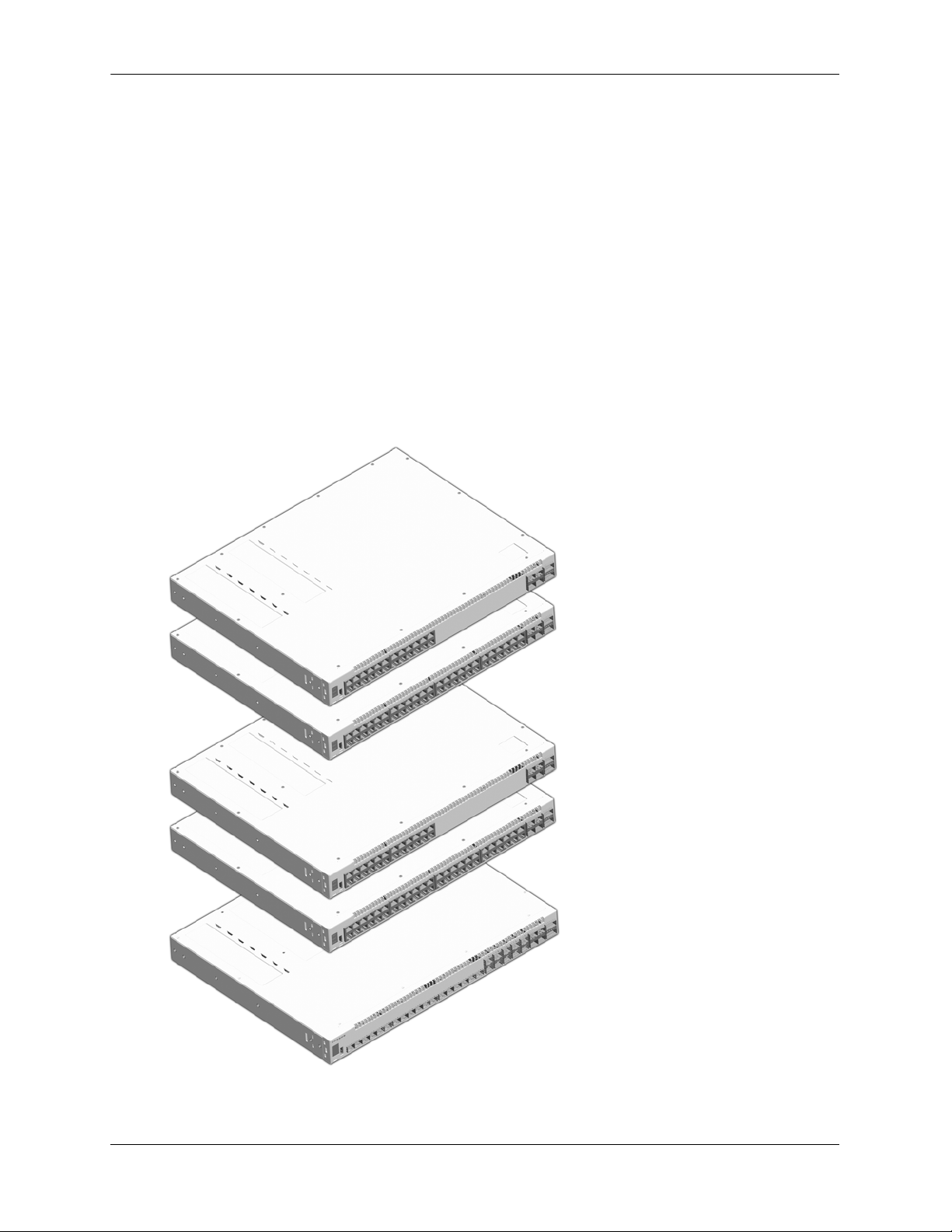
OmniSwitch 6860
OmniSwitch 6860-24/6860E-24
OmniSwitch 6860-48/6860E-48
OmniSwitch 6860-P24/6860E-P24
OmniSwitch 6860-P48/6860E-P48
OmniSwitch 6860E-U28
Additional Chassis Components and Connectors
The OS6860 chassis provides two bays for 1+1 redundant hot-swappable power supplies. (Non-PoE
models allow the installation of a single optional fan tray in place of one 150W power supply.)
All models include one console connector (for use with Micro USB-to-USB cable, included); one USB
connector (for use with Alcatel-Lucent flash drive or Bluetooth dongle, not included); and one RS-232
connector.
Enhanced models, including OS6860E-24, OS6860E-48, OS6860E-48, OS6860E-P48 and OS6860E-U28
provide one Ethernet Management Port (EMP) located on the rear panel for out-of-band management.
For detailed information on the chassis, including front and rear panel connectors and components, refer to
Chapter 3, “Chassis and Power Su pplies.”
For information on console, USB and Bluetooth connections and cable requirements, refer to the
OmniSwitch 6860/OS6860E Switch Management Guide.
page 1-2 OmniSwitch 6860 Hardware Users Guide September 2016
Page 17

OmniSwitch 6860 OmniSwitch 6860 Availability Features
OmniSwitch 6860 Availability Features
The switch provides a broad variety of availability features. Availability features are hardware and
software-based safeguards that help prevent the loss of data flow in the unlikely event of a subsystem
failure. In addition, some availability features allow users to maintain or replace hardware components
without powering off the switch or interrupting switch operations. Combine d, these features provide added
resiliency and help ensure that the switch is consistently available for day-to-day network operations.
Hardware-related availability features include:
• Power Supply Redundancy
• Hot-Swapping
• Hardware Monitoring
Power Supply Redundancy
For information on power supply redun da ncy, refer to Chapter 3, “Chassis and Power Supplies.”
Hot-Swapping
Hot-swapping refers to the action of adding, removing, or replacing certain hardware components without
powering off your switch and disrupting other components in the chassis. This feature greatly facilitates
hardware upgrades and maintenance and also allows you to easily replace components in the unlikely
event of hardware failure. The following hardware components can be hot-swapped:
• Power supplies
• Transceivers
• Plug-in modules
Note. For information on adding and removing power supplies and plug-in modules, refer to Chapter 3,
“Chassis and Power Supplies.”
OmniSwitch 6860 Hardware Users Guide September 2016 page 1-3
Page 18

OmniSwitch 6860 Availability Features OmniSwitch 6860
Hardware Monitoring
Automatic Monitoring
Automatic monitoring refers to the switch’s built-in sensors that automatically monitor operations. If an
error is detected (e.g., over-threshold temperature), the switch immediately sends a trap to the user. The
trap is displayed on the console in the form of a text error message.
LEDs
LEDs, which provide visual status information, are provided on the front and rear panels. LEDs are used
to indicate conditions, such as hardware and software status, link integrity, data flow, etc. For detailed
LED descriptions, refer to the corresponding hardware component section in the next chapter.
User-Driven Monitoring
User-driven hardware monitoring refers to CLI commands that are entered by the user in order to access
the current status of hardware components. The user enters “show” commands that output information to
the console. The show commands for all the features are described in detail in the OmniSwitch CLI
Reference Guide.
page 1-4 OmniSwitch 6860 Hardware Users Guide September 2016
Page 19

2 Getting Started
Installing the Hardware
Note. For information on configuring a Virtual Chassis (VC), refer to the OmniSwitch AOS Release 8
Switch Management Guide.
Items Required
• Grounding wrist strap
• Phillips screwdriver
• Flat-blade screwdriver
Site Preparation
Environmental Requirements
OmniSwitch 6860 switches have the following environmental and airflow requirements:
• The installation site must maintain a temperature between 0° and 45° Celsius (32° and 113° Fahrenhe it)
and not exceed 95 percent maximum humidity (non-condensing) at any time.
• Be sure to allow adequate room for proper air ventilation at the front, back, and sides of the switch.
Refer to “Airflow Considerations” on page 2-4 for minimum clearance requirements. No clearance is
necessary at the top or bottom of the chassis.
Electrical Requirements
Note. Alcatel-Lucent switches must be installed by a professional installer. It is the responsibility of the
installer to ensure that proper grounding is available and that the installation meets applicable local and
national electrical codes.
OmniSwitch 6860 switches have the following general electrical requirements:
• Each switch requires one grounded electrical outlet for each power supply installed in the chassis.
OmniSwitch 6860 switches offer both AC and DC power supply support. Refer to the OmniSwitch
6860 Hardware Users Guide for more information.
• For switches using AC power connections, each supplied AC power cord is 2 meters (approx. 6.5 feet).
Do not use extension cords.
OmniSwitch 6860 Hardware Users Guide September 2016 page 2-1
Page 20

Installing the Hardware Getting Started
Redundant AC Power. It is recommended that each AC outlet resides on a separate circuit. With
redundant AC, if a single circuit fails, the switch’s remaining power supplies (on separate circuits) can
remain operational.
• For switches using DC power, refer to the “DC Power Supply Connections” on page 3-34 for
more information.
Electrical Surge Warning
In order to help protect equipment against electrical surges please take note of the following
recommendations and guidelines:
1 Earth grounding of all devices is fundamental to ensure long term reliability.
• All electrical equipment must be installed by a qualified, licensed electrician.
• Every power supply that is connected to building power shoul d be earth grounded.
• Earth grounding for the power cable, should be verified to be 0.01 ohm or less.
• Each switch should be grounded to same earth ground as the power supply.
• Each powered device, such as an AP or camera, should be connected to earth ground.
• Each surge suppression device should be connected to earth ground.
2 Shielded cables (STP) offer some minimal level of additional protection over unshielded Ethernet
cables (UTP) but the use of a surge protector is still recommended.
• It is suggested to use STP Cat5e or better for 1Gbps Ethernet switches for any outdoor application or
applications where Ethernet cables come in close proximity to alternating current conductors.
• Always install cables according to manufacturer requirements.
3 For any connections where integrity of the cabli ng within a bui lding grou nd is questio nable (i.e ou tdoor
connections), copper Ethernet ports must be connected with an appropriate surge protection device, inline,
between the PSE and PD per the manufacturer’s recommendations for connecti on and grounding.
4 Caution should be taken for any cable connected to any outdoor device, not only on the device ground-
ing, but to ensure that any outdoor device cables that could carry surge currents, do not pass those surge
currents to upstream Ethernet switches.
5 Caution - Category 5e, Category 6, and Category 6a cables can store large amounts of static electricity
due to the dielectric properties of their construction materials in addition, this build up of electricity could
lead to a Cable Discharge Event (CDE). A CDE can occur due to the differential in charges on the cable
and the equipment it’s being connected to. It is recommended that installers momentarily ground all
copper Ethernet cables (especially in new cable runs) to a suitable and safe earth ground before connecting them to the port.
Note. Failure to follow the above recommendations could result in voiding the warranty of the affected
ALE product.
page 2-2 OmniSwitch 6860 Hardware Users Guide September 2016
Page 21

Getting Started Installing the Hardware
Unpacking and Installing the Switch
To protect your switch components from damage, read all unpacking recommendation s and instructions
carefully before beginning.
Unpack your OmniSwitch 6860 chassis as close as possible to the location where it will be in stalled.
Items Included
Your OmniSwitch 6860 includes the following items:
• OmniSwitch chassis with power supplies, per order
• Transceivers, per order
• Blank cover panel
• Rack mount brackets
• Micro USB-to-USB cable
• Country-specific power cord(s)
• Rubber table-mounting feet
• Attachment screws
• Assorted instructional cards, anti-static bags and additional packaging
Weight Considerations
Depending on model type, an empty OmniSwitch 6860 chassis weighs between 4.4 5 kg (9.8 lbs) and
5.03 kg (11.1 lbs).
When fully populated with power supplies and mounting brackets, the Omn iSwitch 6860 can weigh up to
6.49 kg (14.3 lbs). (Weights to not include transceivers or cabling.)
OmniSwitch 6860 Hardware Users Guide September 2016 page 2-3
Page 22
Mounting the Switch Getting Started
}
}
Rear. 6 inches minimum
at rear of chassis.
Front. 6 inches minimum
at front of chassis.
Sides. 2 inches minimum
at left and right sides.
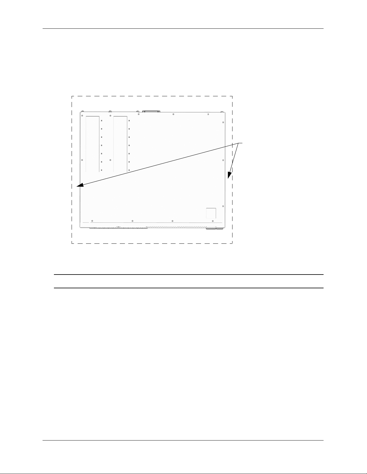
Airflow Considerations
To ensure proper airflow, be sure that your switch is placed in a well-ventilated area and provide minimum
recommended clearance at the front, back and sides of the switch.
Never obstruct chassis air vents.
Chassis Top View
Note. Clearance is not required at the top and bottom of the chassis.
Mounting the Switch
For information on mounting OmniSwitch 6860 switches, refer to the Chapter 3, “Chassis and Power
Supplies.”
page 2-4 OmniSwitch 6860 Hardware Users Guide September 2016
Page 23

Getting Started Connections and Cabling
Connections and Cabling
Once your switch is properly installed, you should connect all network and management cables required for
your network applications. Connections may include:
• Micro USB-to-USB cable to the console connector
• Ethernet cable to the Ethernet Management Port (EMP) (Enhanced models only)
• Cables to NIs or transceivers
Note. For additional information on cabling for console, EMP, USB, Bluetooth and other connections,
refer to the OmniSwitch AOS Release 8 Switch Management Guide.
Network Cable Installation Warning
Never install exposed network cables outdoors. Install network cables per manufacturer requirements.
Serial Connection to the Console Port
The console port provides a serial connection to the switch using a USB connector and is required when
logging into the switch for the first time. By default, this connector provides a DCE console connection.
Serial Connection Default Settings
baud rate 9600
parity none
data bits (word size) 8
stop bits 1
For information on modifying these settings, refer to the OmniSwitch AOS Release 8 Switch
Management Guide.
Ethernet Management Port (EMP) Cable Requirements
Enhanced OS6860 models (OS6860E) provide an Ethernet Management Port (EMP) on the rear panel of the
chassis for out-of-band management. There are specific cable type requirements (i.e., straight-through or
crossover) based on the device to which the EMP is connecting. Refer to the information below:
EMP to a Switch Straight-through
EMP to a Computer or
Workstation
For information on manually configuring Ethernet ports, refer to the OmniS wi tch AOS Release 8 Netw ork
Configuration Guide.
Crossover
OmniSwitch 6860 Hardware Users Guide September 2016 page 2-5
Page 24

Booting the Switch Getting Started
Booting the Switch
Now that you have installed the switch components and connected network and management cables, you can
boot the switch. To boot the switch, plug all power supply cords into easily- accessible, properly grounded
power outlets. (Do not use extension cords.) The switch will power on and boot automatically.
Note. If you have more than one power supply installed, be sure to plug in each power supply in rapid
succession, (i.e., within a few seconds of each other). This ensures that there will be adequ ate power for al l
components throughout the boot process.
Component LEDs
During the boot process, component LEDs will flash and change color, indi cating different stages of the boot.
Following a successful boot, chassis LEDs should display as follows:
OK1 Solid Green
PRI Solid Green (for switches running in
master role)
Solid Amber (for switches running in
slave role)
PS Solid Green
BPS Solid Green
GRN (Power Save) Solid Green
OK2 Solid Green
If the LEDs do not display as indicated, make sure the boot process is complete. If the LEDs do not display as
indicated following a complete boot sequence, contact Alcatel-Lucent Customer Support. For complete
information on LED states, refer to “Chassis Status LEDs” on page 3-19.
Once the switch has completely booted and you have accessed your computer’s terminal emulation software
via the console port, you are ready to log in to the switch’s Command Line Interface (CLI) and configure basic
information. Continue to “Your First Login Session” on page 2-7.
page 2-6 OmniSwitch 6860 Hardware Users Guide September 2016
Page 25

Getting Started Your First Login Session
Your First Login Session
In order to complete the setup process for the switch, you must complete the following steps during your first
login session:
• Log in to the switch
• Set IP address information for the Ethernet Management Port (EMP) (Enhanced models only)
• Unlock session types
• Change the login password
• Set the date and time
• Set optional system information
• Save your changes
Important. You must be connected to the switch via the console port before initiating your first login
session.
Logging In to the Switch
When you first log in to the switch, you will be prompted for a login name and password. Use the switch’s
default settings:
• Login: admin
• Password: switch
The default welcome banner, which includes information such as the current software version and system date,
is displayed followed by the CLI command prompt:
Welcome to the Alcatel-Lucent OS6860E-P48 8.1.1, April 15, 2014.
Copyright (c) 1994-2014 Alcatel-Lucent. All Rights Reserved.
OmniSwitch(tm) is a trademark of Alcatel-Lucent, registered in the United States
Patent and Trademark Office.
->
Note. A user account includes a login name, password, and user privileges. Privileges determine whether
the user has read or write access to the switch and which commands the user is authorized to execute. For
detailed information on setting up and modifying user accounts, refer to the OmniSwitch AOS Release 8
Switch Management Guide.
OmniSwitch 6860 Hardware Users Guide September 2016 page 2-7
Page 26

Your First Login Session Getting Started
Setting IP Address Information for the EMP
If installing an Enhanced OS6860 model (OS6860E), the IP address may be set via the Ethernet Management
Port (EMP). To connect to the switch through the EMP Ethernet connection, use the default address below or
change the port’s IP address.
Default EMP IP Address 192.168.1.1
Default EMP Mask 255.255.255.0
Note. You should be connected to the switch via the console port before attempting to change IP
address information.
To change the default IP and mask, use the ip interface command. For example:
-> ip interface emp address 168.22.2.120 mask 255.255.255.0
Verify your settings using the show ip interface command. See the OmniSwitch AOS Release 8 Switch
Management Guide for additional information regarding EMP port addressing.
Note. Although you have configured the EMP with valid IP address information, you will not be able to
access the switch through this port (i.e. TELNET, FTP, HTTP, SSH or SNMP) until you have unlocked
these remote session types. See “Unlocking Session Types” on page 2-9 for more information.
page 2-8 OmniSwitch 6860 Hardware Users Guide September 2016
Page 27

Getting Started Your First Login Session
Unlocking Session Types
Security is a key feature on OmniSwitch 6860 switches. As described on page 2-7, when you access the switch
for the first time, you must use a direct console port connection. All other session types (Telnet, FTP,
WebView, and SNMP) are locked out until they are manually unlocked by the user.
The CLI command used to unlock session types is aaa authentication.
Note. When you unlock session types, you are granting switch access to non-local sessions (e.g., Telnet).
As a result, users who know the correct user login and password will have remote access to th e switc h. For
more information on switch security, refer to the OmniSwitch AOS Release 8 Switch Management Guide.
Unlocking All Session Types
To unlock all session types, enter the following command syntax at the CLI prompt:
-> aaa authentication default local
Unlocking Specified Session Types
You can also unlock session types on a one-by-one basis. For example, to unlock Telnet sessions only, enter
the following command:
-> aaa authentication telnet local
To unlock WebView (HTTP) sessions only, enter the following command:
-> aaa authentication http local
You cannot specify more than one session type in a single command line. However, you can still unlock
multiple session types by using the aaa authentication command in succession. For example:
-> aaa authentication http local
-> aaa authentication telnet local
-> aaa authentication ftp local
Refer to the OmniSwitch CLI Reference Guide for complete aaa authentication command syntax options.
Changing the Login Password
Change the login password for admin user sessions by following the steps below:
1 Be sure that you have logged into the switch as user type admin (see “Logging In to the Switch” on
page 2-7).
2 Enter the keyword password and press Enter.
3 Enter your new password at the prompt.
Note. Be sure to remember or securely record all new passwords; overriding configured passwords on an
OmniSwitch is restricted.
4 You will be prompted to re-enter the password. Enter the password a second time.
OmniSwitch 6860 Hardware Users Guide September 2016 page 2-9
Page 28

Your First Login Session Getting Started
New password settings are automatically saved in real time to the local user database; the user is not required
to enter an additional command in order to save the password information. Also note that new password
information is retained following a reboot. All subsequent login sessions, including those through the console
port, will require the new password to access the switch.
For detailed information on managing login information, including user names and passwords, refer to the
OmniSwitch AOS Release 8 Switch Management Guide.
Setting the System Time Zone
The switch’s default time zone is UTC. If you require a time zone that is spe cifi c to y ou r region , or if you nee d
to enable Daylight Savings Time (DST) on the switch, you can configure these settings via the system
timezone and system daylight-savings-time commands.
For detailed information on configuring a time zone for the switch, refer to the OmniSwitch AOS Release 8
Switch Management Guide.
Setting the Date and Time
Set the current time for the switch by entering system time, followed by the current time in hh:mm:ss.
To set the current date for the switch, enter system date, followed by the current date in mm/dd/yyyy.
Setting Optional Parameters
Specifying an Administrative Contact
An administrative contact is the person or department in charge of the switch. If a contact is specified, users
can easily find the appropriate network administrator if they have questions or comments about the switch.
To specify an administrative contact, use the system contact command.
Specifying a System Name
The system name is a simple, user-defined text description for the switch. To specify a system name, use the
system name command.
Specifying the Switch’s Location
It is recommended that you use a physical labeling system for locating and identifying your switch(es).
Examples include placing a sticker or placard with a unique identifier (e.g., the switch’s default IP address) on
each chassis.
However, if no labeling system has been implemented or if you need to determine a switch’s location from a
remote site, entering a system location can be very useful.
To specify a system location, use the system location command.
page 2-10 OmniSwitch 6860 Hardware Users Guide September 2016
Page 29

Getting Started Your First Login Session
Viewing Your Changes
To view your current changes, enter show system at the CLI prompt.
Saving Your Changes
Once you have configured this basic switch information, save your changes by entering write memory at the
CLI command prompt.
OmniSwitch 6860 Hardware Users Guide September 2016 page 2-11
Page 30

Your First Login Session Getting Started
page 2-12 OmniSwitch 6860 Hardware Users Guide September 2016
Page 31

3 Chassis and Power Supplies
This chapter includes detailed information on the OmniSwitch 6860 switch. Topics include:
• Chassis details and technical specifications:
Basic Models - Non-PoE
OS6860-24, page 3-2.
OS6860-48, page 3-4.
Basic Models - PoE
OS6860-P24, page 3-6.
OS6860-P48, page 3-8.
Enhanced Models - Non-PoE
OS6860E-24, page 3-10.
OS6860E-48, page 3-12.
OS6860E-U28, page 3-14.
Enhanced Models - PoE
OS6860E-P24, page 3-16.
OS6860E-P48, page 3-18.
• Switch mounting information, page 3-21.
• Power supplies and power supply redundancy, page 3-30.
• Fan tray (non-PoE models only), page 3-40.
• Temperature management, page 3-41.
• Monitoring the chassis components via the Command Line Interface (CLI), page 3-41
OmniSwitch 6860 Hardware Users Guide September 2016 page 3-1
Page 32

OmniSwitch 6860 Chassis Details Chassis and Power Supplies
OS6860-24
USB
VFL
/30
VFL
/29
USB
RS232
OK
PRI PS
BPS
GRN
OS6860-24
USB
VFL
/30
VFL
/29
USB
RS232
OK
PS
BPS
GRN
VC
G
H
DFE
A B
C
PS 1
PS 2
BPS
A B C
OmniSwitch 6860 Chassis Details
Basic Models - Non-PoE
OS6860-24 Front Panel
Item Description
A
B
C
D
E
F
G
H
Virtual Chassis ID LED
Status LEDs
USB port
Console port
RS-232 port
(24) 10/100/1000 Base-T ports
(4) fixed SFP+ (1G/10G) ports
(2) 20G Virtual Chassis link ports
CLASS 1 M LASER CAUTION. CAUTION - CLASS 1 M LASER RADIATION WHEN OPEN.
DO NOT VIEW DIRECTLY WITH OPTICAL INSTRUMENTS
OS6860-24 Rear Panel
Item Description
A
B
C
Chassis Grounding Lug
OmniSwitch Backup Power Supply (OS-BPS) (No longer supported.)
Power Supply/Fan Tray Bays
page 3-2 OmniSwitch 6860 Hardware Users Guide September 2016
Page 33

Chassis and Power Supplies OmniSwitch 6860 Chassis Details
OS6860-24 Chassis Specifications
Chassis Height 4.4 cm (1.73 in)
Chassis Width 44 cm (17.33 in)
Chassis Depth 35 cm (13.78 in)
OS6860-24 Chassis Weight 4.45 kg (9.8 lb)
OS6860-24 Chassis Weight (fully populated)
1
OS6860-24 Power Consumption (full system power) 46 W
Altitude 13,000 ft
Operating Temperature (Tmra) 0°C to 45°C (32°F to 113°F)
Storage Temperature -40°C to 85°C (-40°F to 185°F)
Operating Humidity 5% to 95% non-condensing
Storage Humidity 5% to 95% non-con densi ng
1
Fully populated weights include installed power supplies. These figures do not include transceivers.
5.17 kg (11.4 lb)
*Note On Chassis Versus Ambient Temperatures. Chassis temperature refers to the sensor reading of
the internal switch temperature (threshold or danger). Ambient temperature refers to the approximate room
temperature. The ambient temperature will typically be lower than the chassis temperature.
OmniSwitch 6860 Hardware Users Guide September 2016 page 3-3
Page 34

OmniSwitch 6860 Chassis Details Chassis and Power Supplies
OS6860-48
USB
VFL/54
VFL/53
USB
RS232
OK
PRI PS
BPS
GRN
OS6860-48
USB
VFL/54
VFL/53
USB
RS232
OK
VC PS
BPS
GRN
G
H
DFE
A B
C
PS 1
PS 2
BPS
A B C
OS6860-48 Front Panel
Item Description
A
B
C
D
E
F
G
H
Virtual Chassis ID LED
Status LEDs
USB port
Console port
RS-232 port
(48) 10/100/1000 Base-T ports
(4) fixed SFP+ (1G/10G) ports
(2) 20G Virtual Chassis link ports
CLASS 1 M LASER CAUTION. CAUTION - CLASS 1 M LASER RADIATION WHEN OPEN.
DO NOT VIEW DIRECTLY WITH OPTICAL INSTRUMENTS
OS6860-48 Rear Panel
Item Description
A
B
C
Chassis Grounding Lug
OmniSwitch Backup Power Supply (OS-BPS) (No longer supported.)
Power Supply/Fan Tray Bays
page 3-4 OmniSwitch 6860 Hardware Users Guide September 2016
Page 35

Chassis and Power Supplies OmniSwitch 6860 Chassis Details
OS6860-48 Chassis Specifications
Chassis Height 4.4 cm (1.73 in)
Chassis Width 44 cm (17.33 in)
Chassis Depth 35 cm (13.78 in)
OS6860-48 Chassis Weight 4.67 kg (10.3 lb)
OS6860-48 Chassis Weight (fully populated)
1
OS6860-48 Power Consumption (full system power) 57 W
Altitude 13,000 ft
Operating Temperature (Tmra) 0°C to 45°C (32°F to 113°F)
Storage Temperature -40°C to 85°C (-40°F to 185°F)
Operating Humidity 5% to 95% non-condensing
Storage Humidity 5% to 95% non-con densi ng
1
Fully populated weights include installed power supplies. These figures do not include transceivers.
5.40 kg (11.9 lb)
*Note On Chassis Versus Ambient Temperatures. Chassis temperature refers to the sensor reading of
the internal switch temperature (threshold or danger). Ambient temperature refers to the approximate room
temperature. The ambient temperature will typically be lower than the chassis temperature.
OmniSwitch 6860 Hardware Users Guide September 2016 page 3-5
Page 36

OmniSwitch 6860 Chassis Details Chassis and Power Supplies
G
H
DFE
A B
C
A C DB
Basic Models - PoE
OS6860-P24 Front Panel
VC
BPS
BPS
GRN
GRN
OK
OK
PRI PS
PS
OS6860-P24
OS6860-P24
USB
USB
USB
USB
RS232
RS232
Item Description
VFL/29
VFL/29
VFL/30
VFL/30
A
B
C
D
E
F
G
H
Virtual Chassis ID LED
Status LEDs
USB port
Console port
RS-232 port
(24) 10/100/1000 Base-T PoE ports
(4) fixed SFP+ (1G/10G) ports
(2) 20G Virtual Chassis link ports
CLASS 1 M LASER CAUTION. CAUTION - CLASS 1 M LASER RADIATION WHEN OPEN.
DO NOT VIEW DIRECTLY WITH OPTICAL INSTRUMENTS
OS6860-P24 Rear Panel
Item Description
A
B
C
D
Chassis Grounding Lug
Fan Vent
OmniSwitch Backup Power Supply (OS-BPS) (No longer supported.)
PoE Power Supply Bays
page 3-6 OmniSwitch 6860 Hardware Users Guide September 2016
Page 37

Chassis and Power Supplies OmniSwitch 6860 Chassis Details
OS6860-P24 Chassis Specifications
Chassis Height 4.4 cm (1.73 in)
Chassis Width 44 cm (17.33 in)
Chassis Depth 35 cm (13.78 in)
OS6860-P24 Chassis Weight 4.58 kg (10.1 lb)
OS6860-P24 Chassis Weight (fully populated)
OS6860-P24 Power Consumption (full system power)
1
2
Altitude 13,000 ft
Operating Temperature (Tmra) 0°C to 45°C (32°F to 113°F)
Storage Temperature -40°C to 85°C (-40°F to 185°F)
Operating Humidity 5% to 95% non-condensing
Storage Humidity 5% to 95% non-con densi ng
1
Fully populated weights include installed power supplies. These figures do not include transceivers.
2
Does not include attached PoE devices.
6.03 kg (13.3 lb)
75 W
*Note On Chassis Versus Ambient Temperatures. Chassis temperature refers to the sensor reading of
the internal switch temperature (threshold or danger). Ambient temperature refers to the approximate room
temperature. The ambient temperature will typically be lower than the chassis temperature.
OmniSwitch 6860 Hardware Users Guide September 2016 page 3-7
Page 38

OmniSwitch 6860 Chassis Details Chassis and Power Supplies
G
H
DFE
A B
C
A C DB
OS6860-P48 Front Panel
BPS
BPS
GRN
GRN
OK
OK
VC PS
PRI PS
OS6860-P48
OS6860-P48
USB
USB
USB
USB
RS232
RS232
Item Description
VFL/53
VFL/53
VFL/54
VFL/54
A
B
C
D
E
F
G
H
Virtual Chassis ID LED
Status LEDs
USB port
Console port
RS-232 port
(48) 10/100/1000 Base-T PoE ports
(4) fixed SFP+ (1G/10G) ports
(2) 20G Virtual Chassis link ports
CLASS 1 M LASER CAUTION. CAUTION - CLASS 1 M LASER RADIATION WHEN OPEN.
DO NOT VIEW DIRECTLY WITH OPTICAL INSTRUMENTS
OS6860-P48 Rear Panel
Item Description
A
B
C
D
Chassis Grounding Lug
Fan Vent
OmniSwitch Backup Power Supply (OS-BPS) (No longer supported.)
PoE Power Supply Bays
page 3-8 OmniSwitch 6860 Hardware Users Guide September 2016
Page 39

Chassis and Power Supplies OmniSwitch 6860 Chassis Details
OS6860-P48 Chassis Specifications
Chassis Height 4.4 cm (1.73 in)
Chassis Width 44 cm (17.33 in)
Chassis Depth 35 cm (13.78 in)
OS6860-P48 Chassis Weight 4.90 kg (10.8 lb)
OS6860-P48 Chassis Weight (fully populated)
OS6860-P48 Power Consumption (full system power)
1
2
Altitude 13,000 ft
Operating Temperature (Tmra) 0°C to 45°C (32°F to 113°F)
Storage Temperature -40°C to 85°C (-40°F to 185°F)
Operating Humidity 5% to 95% non-condensing
Storage Humidity 5% to 95% non-con densi ng
1
Fully populated weights include installed power supplies. These figures do not include transceivers.
2
Does not include attached PoE devices.
6.35 kg (14.0 lb)
89 W
*Note On Chassis Versus Ambient Temperatures. Chassis temperature refers to the sensor reading of
the internal switch temperature (threshold or danger). Ambient temperature refers to the approximate room
temperature. The ambient temperature will typically be lower than the chassis temperature.
OmniSwitch 6860 Hardware Users Guide September 2016 page 3-9
Page 40

OmniSwitch 6860 Chassis Details Chassis and Power Supplies
OS6860E-24
USB
VFL
/30
VFL
/29
PRI PS BPS OK2GRNOK1
USB
RS232
G
H
DFE
A B
C
EMP
PS 1
PS 2
BPS
A B C D
Enhanced Models - Non-PoE
OS6860E-24 Front Panel
Item Description
A
B
C
D
E
F
G
H
Virtual Chassis ID LED
Status LEDs
USB port
Console port
RS-232 port
(24) 10/100/1000 Base-T ports
(4) fixed SFP+ (1G/10G) ports
(2) 20G Virtual Chassis link ports
CLASS 1 M LASER CAUTION. CAUTION - CLASS 1 M LASER RADIATION WHEN OPEN.
DO NOT VIEW DIRECTLY WITH OPTICAL INSTRUMENTS
OS6860E-24 Rear Panel
Item Description
A
B
C
D
Chassis Grounding Lug
Ethernet Management Port (EMP) for Out-of-Band Management
OmniSwitch Backup Power Supply (OS-BPS) (No longer supported.)
Power Supply/Fan Tray Bays
page 3-10 OmniSwitch 6860 Hardware Users Guide September 2016
Page 41

Chassis and Power Supplies OmniSwitch 6860 Chassis Details
OS6860E-24 Chassis Specifications
Chassis Height 4.4 cm (1.73 in)
Chassis Width 44 cm (17.33 in)
Chassis Depth 35 cm (13.78 in)
OS6860E-24 Chassis Weight 4.58 kg (10.1 lb)
OS6860E-24 Chassis Weight (fully populated)
1
OS6860E-24 Power Consumption (full system power) 48 W
Altitude 13,000 ft
Operating Temperature (Tmra) 0°C to 45°C (32°F to 113°F)
Storage Temperature -40°C to 85°C (-40°F to 185°F)
Operating Humidity 5% to 95% non-condensing
Storage Humidity 5% to 95% non-con densi ng
1
Fully populated weights include installed power supplies. These figures do not include transceivers.
5.26 kg (11.6 lb)
*Note On Chassis Versus Ambient Temperatures. Chassis temperature refers to the sensor reading of
the internal switch temperature (threshold or danger). Ambient temperature refers to the approximate room
temperature. The ambient temperature will typically be lower than the chassis temperature.
OmniSwitch 6860 Hardware Users Guide September 2016 page 3-11
Page 42

OmniSwitch 6860 Chassis Details Chassis and Power Supplies
G
H
DFE
A B
C
EMP
PS 1
PS 2
BPS
A B C D
OS6860E-48 Front Panel
PRI PS BPS OK2GRNOK1
OS6860E-48
USB
RS232
Item Description
A
B
C
D
E
F
G
H
Virtual Chassis ID LED
Status LEDs
USB port
Console port
RS-232 port
(48) 10/100/1000 Base-T ports
(4) fixed SFP+ (1G/10G) ports
(2) 20G Virtual Chassis link ports
CLASS 1 M LASER CAUTION. CAUTION - CLASS 1 M LASER RADIATION WHEN OPEN.
DO NOT VIEW DIRECTLY WITH OPTICAL INSTRUMENTS
VFL
/53
VFL
/54
OS6860E-48 Rear Panel
Item Description
A
B
C
D
Chassis Grounding Lug
Ethernet Management Port (EMP) for Out-of-Band Management
OmniSwitch Backup Power Supply (OS-BPS) (No longer supported.)
Power Supply/Fan Tray Bays
page 3-12 OmniSwitch 6860 Hardware Users Guide September 2016
Page 43

Chassis and Power Supplies OmniSwitch 6860 Chassis Details
OS6860E-48 Chassis Specifications
Chassis Height 4.4 cm (1.73 in)
Chassis Width 44 cm (17.33 in)
Chassis Depth 35 cm (13.78 in)
OS6860E-48 Chassis Weight 4.81 kg (10.6 lb)
OS6860E-48 Chassis Weight (fully populated)
1
OS6860E-48 Power Consumption (full system power) 60 W
Altitude 13,000 ft
Operating Temperature (Tmra) 0°C to 45°C (32°F to 113°F)
Storage Temperature -40°C to 85°C (-40°F to 185°F)
Operating Humidity 5% to 95% non-condensing
Storage Humidity 5% to 95% non-con densi ng
1
Fully populated weights include installed power supplies. These figures do not include transceivers.
5.49 kg (12.1 lb)
*Note On Chassis Versus Ambient Temperatures. Chassis temperature refers to the sensor reading of
the internal switch temperature (threshold or danger). Ambient temperature refers to the approximate room
temperature. The ambient temperature will typically be lower than the chassis temperature.
OmniSwitch 6860 Hardware Users Guide September 2016 page 3-13
Page 44

OmniSwitch 6860 Chassis Details Chassis and Power Supplies
G
H
DFE
A B
C
EMP
PS 1
PS 2
BPS
A B C D
OS6860E-U28 Front Panel
Item Description
A
B
C
D
E
F
G
H
Virtual Chassis ID LED
Status LEDs
USB port
Console port
RS-232 port
(28) 1000Base-X/100Base-FX ports
(4) fixed SFP+ (1G/10G) ports
(2) 20G Virtual Chassis link ports
CLASS 1 M LASER CAUTION. CAUTION - CLASS 1 M LASER RADIATION WHEN OPEN.
DO NOT VIEW DIRECTLY WITH OPTICAL INSTRUMENTS
OS6860E-U28 Rear Panel
Item Description
A
B
C
D
Chassis Grounding Lug
Ethernet Management Port (EMP) for Out-of-Band Management
OmniSwitch Backup Power Supply (OS-BPS) (No longer supported.)
Power Supply/Fan Tray Bays
page 3-14 OmniSwitch 6860 Hardware Users Guide September 2016
Page 45

Chassis and Power Supplies OmniSwitch 6860 Chassis Details
OS6860E-U28 Chassis Specifications
Chassis Height 4.4 cm (1.73 in)
Chassis Width 44 cm (17.33 in)
Chassis Depth 35 cm (13.78 in)
OS6860E-U28 Chassis Weight 4.58 kg (10.1 lb)
OS6860E-U28 Chassis Weight (fully populated)
1
OS6860E-U28 Power Consumption (full system pow er) 73 W
Altitude 13,000 ft
Operating Temperature (Tmra) 0°C to 45°C (32°F to 113°F)
Storage Temperature -40°C to 85°C (-40°F to 185°F)
Operating Humidity 5% to 95% non-condensing
Storage Humidity 5% to 95% non-con densi ng
1
Fully populated weights include installed power supplies. These figures do not include transceivers.
5.26 kg (11.6 lb)
*Note On Chassis Versus Ambient Temperatures. Chassis temperature refers to the sensor reading of
the internal switch temperature (threshold or danger). Ambient temperature refers to the approximate room
temperature. The ambient temperature will typically be lower than the chassis temperature.
OmniSwitch 6860 Hardware Users Guide September 2016 page 3-15
Page 46

OmniSwitch 6860 Chassis Details Chassis and Power Supplies
OS6860E-P24
USB
VFL/30
VFL/29
PRI PS BPS OK2GRNOK1
USB
RS232
G
H
DFE
A B
C
A B D EC
Enhanced Models - PoE
OS6860E-P24 Front Panel
Item Description
A
B
C
D
E
F
G
H
Virtual Chassis ID LED
Status LEDs
USB port
Console port
RS-232 port
(24) 10/100/1000 Base-T PoE ports
(4) fixed SFP+ (1G/10G) ports
(2) 20G Virtual Chassis link ports
CLASS 1 M LASER CAUTION. CAUTION - CLASS 1 M LASER RADIATION WHEN OPEN.
DO NOT VIEW DIRECTLY WITH OPTICAL INSTRUMENTS
OS6860E-P24 Rear Panel
Item Description
A
B
C
D
E
Chassis Grounding Lug
Ethernet Management Port (EMP) for Out-of-Band Management
Fan Vent
OmniSwitch Backup Power Supply (OS-BPS) (No longer supported.)
Power Supply Bays
page 3-16 OmniSwitch 6860 Hardware Users Guide September 2016
Page 47

Chassis and Power Supplies OmniSwitch 6860 Chassis Details
OS6860E-P24 Chassis Specifications
Chassis Height 4.4 cm (1.73 in)
Chassis Width 44 cm (17.33 in)
Chassis Depth 35 cm (13.78 in)
OS6860E-P24 Chassis Weight 4.81 kg (10.6 lb)
OS6860E-P24 Chassis Weight (fully populated)
OS6860E-P24 Power Consumption (full system power)
1
2
Altitude 13,000 ft
Operating Temperature (Tmra) 0°C to 45°C (32°F to 113°F)
Storage Temperature -40°C to 85°C (-40°F to 185°F)
Operating Humidity 5% to 95% non-condensing
Storage Humidity 5% to 95% non-con densi ng
1
Fully populated weights include installed power supplies. These figures do not include transceivers.
2
Does not include attached PoE devices.
6.26 kg (13.8 lb)
76 W
*Note On Chassis Versus Ambient Temperatures. Chassis temperature refers to the sensor reading of
the internal switch temperature (threshold or danger). Ambient temperature refers to the approximate room
temperature. The ambient temperature will typically be lower than the chassis temperature.
OmniSwitch 6860 Hardware Users Guide September 2016 page 3-17
Page 48

OmniSwitch 6860 Chassis Details Chassis and Power Supplies
OS6860E-P48
USB
VFL/54
VFL/53
USB
RS232
PRI PS BPS OK2GRNOK1
G
H
DFE
A B
C
A B D EC
OS6860E-P48 Front Panel
Item Description
A
B
C
D
E
F
G
H
Virtual Chassis ID LED
Status LEDs
USB port
Console port
RS-232 port
(48) 10/100/1000 Base-T PoE ports
(4) fixed SFP+ (1G/10G) ports
(2) 20G Virtual Chassis link ports
CLASS 1 M LASER CAUTION. CAUTION - CLASS 1 M LASER RADIATION WHEN OPEN.
DO NOT VIEW DIRECTLY WITH OPTICAL INSTRUMENTS
OS6860E-P48 Rear Panel
Item Description
A
B
C
D
E
Chassis Grounding Lug
Ethernet Management Port (EMP) for Out-of-Band Management
Fan Vent
OmniSwitch Backup Power Supply (OS-BPS) (No longer supported.)
Power Supply Bays
page 3-18 OmniSwitch 6860 Hardware Users Guide September 2016
Page 49

Chassis and Power Supplies OmniSwitch 6860 Chassis Details
OS6860E-P48 Chassis Specifications
Chassis Height 4.4 cm (1.73 in)
Chassis Width 44 cm (17.33 in)
Chassis Depth 35 cm (13.78 in)
OS6860E-P48 Chassis Weight 5.03 kg (11.1 lb)
OS6860E-P48 Chassis Weight (fully populated)
OS6860E-P48 Power Consumption (full system power)
1
2
Altitude 13,000 ft
Operating Temperature (Tmra) 0°C to 45°C (32°F to 113°F)
Storage Temperature -40°C to 85°C (-40°F to 185°F)
Operating Humidity 5% to 95% non-condensing
Storage Humidity 5% to 95% non-con densi ng
1
Fully populated weights include installed power supplies. These figures do not include transceivers.
1
Does not include attached PoE devices.
6.49 kg (14.3 lb)
93 W
*Note On Chassis Versus Ambient Temperatures. Chassis temperature refers to the sensor reading of
the internal switch temperature (threshold or danger). Ambient temperature refers to the approximate room
temperature. The ambient temperature will typically be lower than the chassis temperature.
Chassis Status LEDs
The chassis provides a series of status LEDs located on the front panel. These LEDs offer basic status
information for hardware operation and port link and activity status.
LED State Description
OK1 Solid Green
Blinking Green
Solid Amber
VC Solid Green
Solid Amber
Off
System Diagnostics and AOS bootup OK
System Diagnostics and AOS in progress
(i.e., performing diagnostics or booting)
System Diagnostics and/or AOS bootup failed
This unit is the master unit
This unit is a slave unit
This unit is in shutdown mode or is not part of
a VC.
OmniSwitch 6860 Hardware Users Guide September 2016 page 3-19
Page 50

OmniSwitch 6860 Chassis Details Chassis and Power Supplies
LED State Description
PS Solid Green
Solid Green
Solid Amber
Solid Amber
Off
BPS Solid Green
Solid Amber
Off
GRN Solid Green
T wo power supplies are installed in the chassis
and both supplies are functioning normally.
One power supplies is installed in the chassis
and functioning normally (with the second
power supply bay empty or occupied by a
fan tray).
T wo power supplies are installed in the chassis
and one or both supplies has experienced
a failure.
One power supply is installed in the chassis
and has experienced a failure (with the second
power supply bay empty or occupied by a
fan tray).
No power supply is present.
Backup power supply is operating normally
Backup power supply is operating, but a fault
is present
No backup power supply is present
Power save features are active
Off
OK2 (Enhanced
Solid Green
models only)
Blinking Green
Solid Amber
Port LEDs Solid Green
Blinking Green
Solid Amber
Blinking Amber
Power save features are off
External CPU Diagnostics and AO S
bootup OK
External CPU Diagnostics in progress
External CPU Diagnostic and/or AOS
bootup failed
Valid port link (non-PoE)
Valid port link with activity (non-PoE)
Valid port link (PoE)
Valid port link with activity (PoE)
page 3-20 OmniSwitch 6860 Hardware Users Guide September 2016
Page 51

Chassis and Power Supplies Mounting the Switch
Mounting the Switch
General Mounting Recommendations
Elevated Operating Ambient Temperature. If installed in a closed or multi-rack assembly, the
operating ambient temperature of the rack environment may be greater than the room’s ambient
temperature. Therefore, consideration should be given to the maximum rated ambient temperature (Tmra)
listed in the “OmniSwitch 6860 Chassis Details” section.
Reduced Air Flow. Installation of the equipment in a rack should be such that the amount of air flow
required for safe operation of the equipment is not compromised. Refer to “Airflow Recommendations”
on page 3-22 for more information.
Mechanical Loading. Mounting of the equipment in the rack should be such that a hazardous conditi on is
not achieved due to uneven loading.
Circuit Overloading. Consideration should be give to the connection of the equipment to the supply
circuit and the effect that overloading of circuits could have on overcurrent protection and supply wiring.
Reliable Earthing. Reliable earthing of rack-mounted equipment should be maintaine d. Pa rt icu lar
attention should be given to supply connections other than direct connections to the branch (e.g., use of
power strips).
OmniSwitch 6860 Hardware Users Guide September 2016 page 3-21
Page 52

Mounting the Switch Chassis and Power Supplies
}
}
Rear. 6 inches minimum
at rear of chassis.
Front. 6 inches minimum
at front of chassis.
Sides. 2 inches minimum
at left and right sides.
Airflow Recommendations
To ensure proper airflow, be sure that your switch is pl aced i n a wel l-ventilated area and provide minimum
recommended clearance at the front, back and sides of the switch, as shown below. Restricted airflow can
cause your switch to overheat, which can lead to switch failure. Refer to the following important
guidelines regarding airflow:
Follow the guidelines below regarding the minimum clearance requirements when mounting
the chassis.
Chassis Top View
Note. Clearance is not required at the top and bottom of the chassis.
page 3-22 OmniSwitch 6860 Hardware Users Guide September 2016
Page 53

Chassis and Power Supplies Mounting the Switch
Face arrow up
when installing.
Blank Cover Panels
Blank cover panels are provided with your switch and are used to cover empty slots. These cover panels
play an important role in chassis airflow and temperature management. If your switch is not fully
populated and blank cover panels are not installed over empty slot locations, airflow is adversely affected.
When blank cover panels are missing, air does not take the direct route from the air intake vents. As a
result, normal airflow is disrupted and an extra task is placed on the power supply fans to cool the chassis.
Cover panels also provide protection for module processor boards and other sensi tive internal switch
components by closing off a chassis that is not fully populated.
Note. Because they regulate airflow and help protect internal chassis components, blank cover panels
should be installed over empty module slots and power supply bays at all times.
Installing Blank Cover Panels
1 When installing blank cover panels over power supply slots, orient the cover panels with the arrows
pointing up.
2 Insert the blank cover panel in the empty chassis slot and secure using attachment screws (provided).
OmniSwitch 6860 Hardware Users Guide September 2016 page 3-23
Page 54

Rack-Mounting Chassis and Power Supplies
Slot
Tab
Clip in “Out”
(disengaged)
position
Rack-Mounting
Refer to the following important guidelines before installing the chassis in a rack:
• Two people are required to rack mount the switch: One person to lift the chassi s in to position and one
person to secure the chassis to the rack using the rack mount screws.
• The chassis has rack-mount flanges that support standard 19-inch rack mount installations.
• Alcatel-Lucent Enterprise does not provide rack-mount screws. Use the screws supplied by the
rack vendor.
• To prevent a rack from becoming top heavy, it is recommended that you install the switch at the bottom
of the rack whenever possible.
Note. If you are installing the switch in a relay rack, be sure to install and secure the rack per rack manufacturer’s specifications.
Installing Rack Mount Flanges
1 To install rack mount flanges, start by making sure the spring clip is i n the out (disengaged) position.
2 Insert the tab into the chassis slot as shown.
page 3-24 OmniSwitch 6860 Hardware Users Guide September 2016
Page 55

Chassis and Power Supplies Rack-Mounting
Clip in “In”
(engaged)
position
“CLICK”
3 Press the flange and spring clip until the flange clicks into place and the clip is in the in
(engaged) position.
4 Secure the flange to the chassis using the attachment screw (provided).
5 Repeat steps 1 through 4 for the flange on the opposite side of the chassis.
OmniSwitch 6860 Hardware Users Guide September 2016 page 3-25
Page 56

Rack-Mounting Chassis and Power Supplies
Installing the Chassis In the Rack
1 Mark the holes on the rack where the chassis is to be installed.
2 One person should lift and position the chassis until the rack-mount flanges are flush with the
rack post.
3 Align the holes in the flanges with the rack holes marked in step 1.
4 Once the holes are aligned, the second person should insert a screw through the bottom hole on each
flange. Tighten both screws until they are secure.
5 Install the remaining screws in the top hole of each flange. Be sure that all screws are
securely tightened.
page 3-26 OmniSwitch 6860 Hardware Users Guide September 2016
Page 57

Chassis and Power Supplies Rack-Mounting
Standalone (Non-Rack Mounted) Installations
The chassis can also be placed unmounted on a stable, flat surface as a standalone unit. Be sure that the
surface can accommodate the full, populated weight of all switches being installed. (Approximate chassis
weights are provided in the technical specifications tables in the “OmniSwitch 6860 Chassis Details”
section.)
Be sure that adequate clearance has been provided for chassis airflow and that you have placed the chassis
within reach of all required AC outlets. For recommended airflow allowances, refer to page 3-22.
To prepare the chassis for tabletop installations, follow the steps below:
1 Insert the four (4) rubber feet (provided separa tely in t he swi tch pa ckagi ng) in to the hole s in th e bott om
panel of the chassis.
2 Place the switch on the tabletop “right side up.”
Note. Never attempt to operate a switch while it is placed on its top or side.
3 Connect network and management cables as needed.
OmniSwitch 6860 Hardware Users Guide September 2016 page 3-27
Page 58

Power Supplies Chassis and Power Supplies
Power Supplies
OmniSwitch 6860 switches use four (4) power sup pl y typ es:
Model Chassis Supported
OS6860-BP 150W AC
Non-PoE PSU
OS6860-BP-D 150W DC
Non-PoE PSU
OS6860-BP-PH 600W AC
PoE PSU
OS6860-BP-PX 920W AC
PoE PSU
OmniSwitch 6860 power supp li es are loca ted at t he re ar of the swit ch chassis. Refer to “OmniSwitch 6860
Chassis Details” for more information on component locations. Two slots are provided. If a second power
supply is installed, it will assume a standby role.
Please note that the OS6860 does not provide an on/off switch. Connecting an installed power supply to a
power source will boot the switch. Likewise, disconnecting all installed power supplies from a power
source will power off the switch.
OS6860-24, OS6860E-24, OS6860-48, OS6860E-48,
OS6860E-U28
OS6860-24, OS6860E-24, OS6860-48, OS6860E-48,
OS6860E-U28
OS6860-P24, OS6860E-P24
OS6860-P48, OS6860E-P48
page 3-28 OmniSwitch 6860 Hardware Users Guide September 2016
Page 59

Chassis and Power Supplies Power Supplies
Dying Gasp
If the switch loses all power it will maintain power long enough to send a Dying Gasp message before
completely shutting down. An SNMP trap, Syslog message and Link OAM PDUs will be generated.
Scenarios
A Dying Gasp event will be generated in the following scenarios:
• Primary power supply failure (if only power supply present)
• Primary power supply failure and then backup power supply failure
• Backup power supply failure and then primary power supply failure
• When a reload command is issued
• When a takeover command is issued
Note. Connect each power supply to a separate independent power source to avoid simultaneous
power failures.
SNMP Trap
As soon as the power failure is detected, an SNMP trap is se nt to the first three configured SNMP stations.
The trap includes the follow ing information:
• Slot number
• Power supply type (primary/backup)
• Time of the failure
Use the snmp station command and refer to the SNMP Configuration chapter for information on
configuring an SNMP station.
Syslog Message
As soon as the power failure is detected, the following Syslog message is sent to the first four configured
Syslog servers, along with the time of the failure:
Dying Gasp Power Failure Event Occurred
Use the swlog output socket command to add a Syslog station. Refer to the Using Switch Logging
Configuration chapter in the Network Configuration Guide for information on configuring a Syslog server.
OmniSwitch 6860 Hardware Users Guide September 2016 page 3-29
Page 60

Power Supplies Chassis and Power Supplies
Handle
Status LED
Air Vent
Lock Ta b
AC Connector
OS6860-BP 150W Power Supply
LED
OS6860-BP 150W AC Power Supply Front Panel
Model OS6860-BP
Models Supported OS6860-24, OS6860E-24, OS6860-48, OS6860E-48
Input Voltage/Current 90 V to 136 V AC /3 A
180 V to 264 VAC /1.5 A
Input Frequency 47 Hz to 63 Hz
Max. Output Power/Current 150 W/12.5 A
OS6860-BP LED States
LED State Description
Solid Green The power supply is operating normally and providing power
Flashing Green The power supply is on standby and can provide power to the chassis if
Flashing Red No AC power is being provided to this power supply (but another power
Flashing Green/Red Power supply warning
Solid Red Power supply failure
Off No AC power is being provided to any power supply installed in the
power supply failover should occur
supply is installed and operating in the adjacent power supply bay)
chassis; all power supplies are effectively off
page 3-30 OmniSwitch 6860 Hardware Users Guide September 2016
Page 61

Chassis and Power Supplies Power Supplies
LED
Handle
Status LED
Air Vent
Lock Ta b
DC Connector
OS6860-BP-D 150W DC Power Supply
OS6860-BP-D 150W DC Power Supply Front Panel
Model OS6860-BP-D
Models Supported OS6860-24, OS6860E-24, OS6860-48, OS6860E-48
Input Voltage/Current -36 V to-72 V DC/1.8 A to 6 A
Max. Output Power/Current 150 W/12.5 A
OS6860-BP-D LED States
LED State Description
Solid Green The power supply is operating normally and providing power
Flashing Green The power supply is on standby and can provide power to the chassis if
Flashing Red No AC power is being provided to this power supply (but another power
Flashing Green/Red Power supply warning
Solid Red Power supply failure
Off No power is being provided to any power supply installed in the chassis;
power supply failover should occur
supply is installed and operating in the adjacent power supply bay)
all power supplies are effectively off
OmniSwitch 6860 Hardware Users Guide September 2016 page 3-31
Page 62

Power Supplies Chassis and Power Supplies
AC Connector
Air Vent
Lock Tab
Status LEDs
OS6860-BP-PH 600W Power Supply
OS6860-BP-PH 600W AC Power Supply Front Panel
Model OS6860-BP-PH
Models Supported OS6860-P24, OS6860E-P24
Input Voltage/Current 90 V to 136 V AC /8.5 A
180 V to 264 V AC/4.25 A
Input Frequency 47 Hz to 63 Hz
Max. Output Power/Current 600 W/11 A
Max. Output for System Power 150W
Max. Output for PoE Power 450W
Note. Mixing different wattage power supplies (e.g., 600W and 920W) in a switch chassis is not
supported. Redundant power supplies must be like models.
Load Sharing Support. When two 600W PoE power supplies are installed, each power supply provides
electrical load sharing for PoE. For example, two 600W power suppl ies provide 450W + 450W (or 900W)
in total PoE power.
OS6860-BP-PH LED States
LED State Description
AC OK LED Solid Green AC power is good
AC OK LED Solid Red There is an AC power issue
DC OK LED Solid Green DC power is good
DC OK LED Solid Red There is a DC power issue
page 3-32 OmniSwitch 6860 Hardware Users Guide September 2016
Page 63

Chassis and Power Supplies Power Supplies
AC Connector
Air Vent
Lock Tab
Status LEDs
OS6860-BP-PX 920W Power Supply
OS6860-BP-PX 920W AC Power Supply Front Panel
Model
Models Supported OS6860-P48, OS6860E-P48
Input Voltage/Current 90 V to 136 V AC/13 A
180 V to 264 V AC/6.5 A
Input Frequency 47 Hz to 63 Hz
Max. Output Power/Current 920 W/16.88 A
Max. Output for System Power 140W
Max. Output for PoE Power 780W
Note. Mixing different wattage power supplies (e.g., 600W and 920W) in a switch chassis is not
supported. Redundant power supplies must be like models.
Load Sharing Support. When two 920W PoE power supplies are installed, each power supply provides
electrical load sharing for PoE. For example, two 920W power supplies provide 780W + 780W
(or 1560W) in total PoE power.
OS6860-BP-PX LED States
LED State Description
AC OK LED Solid Green AC power is good
AC OK LED Solid Red There is an AC power issue
DC OK LED Solid Green DC power is good
DC OK LED Solid Red There is a DC power issue
OmniSwitch 6860 Hardware Users Guide September 2016 page 3-33
Page 64

Power Supplies Chassis and Power Supplies
DC Power Supply Connections
Connecting a DC Cable Harness to the Chassis Power Supply
When plugging in the cable, insert the connector end of the cable harness into the power supply connector
until it clicks firmly into place. This is an indication that the connector is secure and properly seated.
Connecting a DC Cable Harness to the DC Power Source
Safety Guidelines
Before connecting the DC cable to a power source, be sure to follow these important guidelines:
• Connect to a reliably ground -48VDC Selv source.
• The branch circuit overcurrent protection must be rated 15A.
• Use 12AWG copper conductors.
• A readily accessible disconnect device that is suitably approved and rated shall be incorporated in the
field wiring.
• It must be installed in a restricted access location.
Primary Ground Information
The product has been designed to be installed in a Common Bonding Network (CBN). The pin of the
Green/Yellow ground lead in the three pin cable connector is connected to th e ground con nector o n the DC
power supply, which is identified by a Grounding symbol. The Green/Yellow lead wire at the other end of
the cable must be connected to a proper earth ground point.
The rear chassis has two ground holes. To properly ground the equipment, connect a Panduit Corporation
UL listed Lug, (Part number LCD8-10A-L) to the two threaded holes located at the rear, insert two 10-32,
3/8” threaded pan head screws into these ground holes, and connect them to a proper earth ground point,
using protective earthing conductor wire and 8AWG copper conductors.
Connection Details
For DC power supply units, make the following power connections:
Connect the power supply using the supplied DC cable. The cable consists of three 12AWG wires (Green/
Yellow, Black, Red).
One end of the cable has a three pin connector in a plastic housing that is inserted into a three pin input
connector on the power supply. The other end of the cable is connected to a fuse panel or other source of
-48VDC power.
Observe proper polarity when connecting to a fuse panel. The cable wire leads must be connected as
follows:
• Green/yellow - ground
• Black - return
• Red - -48VDC
Note. The battery return conductor is an Isolated DC Return (DC-1).
page 3-34 OmniSwitch 6860 Hardware Users Guide September 2016
Page 65

Chassis and Power Supplies Power Supplies
Lock Tab
Installing Power Supplies
Note. The power supply shown in the following diagrams is a OS6860-BP-PH/OS6860-BP-PX unit.
However, comparable installation and removal steps also apply to OS6860-BP and OS6860-BP-D power
supply units, as well as the OS6860 FANTRAY NONPOE Fan Tray (see page 3-40).
1 Insert the power supply into a power supply bay at the rear of the chassis and slide it back until it is
securely seated in the chassis backplane.
When the connector is fully seated, the lock tab will click and hold the power supply in place.
OmniSwitch 6860 Hardware Users Guide September 2016 page 3-35
Page 66

Power Supplies Chassis and Power Supplies
2 Plug the power cord (provided) into the power supply’s socket.
Note. The chassis does not provide an on/off switch. Connecting a the power supplies to a power source
will boot the switch.
page 3-36 OmniSwitch 6860 Hardware Users Guide September 2016
Page 67

Chassis and Power Supplies Power Supplies
Lock Tab
Removing Power Supplies
1 When removing a power supply, first disconnect the power cord from the power source. Once the
power cord is disconnected, pull the power cord out of the power supply housing.
2 Pressing the lock tab toward the center of the power supply, as shown, will free the power supply from
the chassis.
OmniSwitch 6860 Hardware Users Guide September 2016 page 3-37
Page 68

Power Supplies Chassis and Power Supplies
3 While pressing the lock tab, pull the power supply straight back and ou t of the chassis slot.
Note. If you are not replacing the power supply, be sure to install a blank cover panel over the empt y
power supply bay.
page 3-38 OmniSwitch 6860 Hardware Users Guide September 2016
Page 69

Chassis and Power Supplies Grounding the Chassis
Grounding the Chassis
The switch has a grounding lug located on the rear of the chassis. This lug uses 10-32 screws and is
surrounded by a small paint-free area, which provides metal-to-metal contact for a ground connection.
Use this connector to supplement the ground provided by the AC power cord. To do so, install a Panduit
Grounding Lug (type LCD8-10A-L) using 8AWG copper conductors to the paint-free area.
Refer to the rear chassis views on page 3-2 for location details.
OmniSwitch 6860 Hardware Users Guide September 2016 page 3-39
Page 70

OS6860 FANTRAY NONPOE Fan Tray Chassis and Power Supplies
Handle
Status LED
Air Vent
Lock Ta b
OS6860 FANTRAY NONPOE Fan Tray
The OS6860 FANTRAY NONPOE provides supplemental system cooling for non-PoE OS6860 switches
connected to the OmniSwitch Backup Power Shelf/System (BPS).
Note. For information on installing or removing the OS6860 FANTRAY NONPOE unit, follow the steps
outlined for power supplies beginning on page 3-35.
LED
OS6860 FANTRAY NONPOE Front Panel
Model OS6860 FANTRAY NONPOE
Models Supported OS6860-24, OS6860E-24, OS6860-48, OS6860E-48 ,
OS6860E-U28
OS6860 FANTRAY NONPOE LED States
LED State Description
Solid Green Fan tray is receiving power and operating normally
Off The fan tray is off or a failure has occurred
page 3-40 OmniSwitch 6860 Hardware Users Guide September 2016
Page 71

Chassis and Power Supplies Monitoring Chassis Components
Monitoring Chassis Components
Viewing Chassis Slot Information
To view basic slot information, enter the show module command at the CLI prompt:
-> show module
To view more detailed information, use the show module long command:
-> show module long
Monitoring Chassis Temperature
The operating temperature of your switch is a critical factor in its overall operability. In order to avoid a
temperature-related system failure, your switch must always run at a temperature within the specified
operating temperature range.
To avoid chassis over-temperature conditions, follow the important chassis airflow recommendations on
page 3-22.
To check the switch’s current temperature status, use the show temperature command. For example:
-> show temperature
Chassis/Device | Current | Range | Danger | Thresh | Status
---------------+---------+---------+--------+--------+---------------- 1/CMMA 54 15-93 93 96 UNDER THRESHOLD
1/Slot1 54 15-93 93 101 UNDER THRESHOLD
2/CMMA 39 15-85 85 88 UNDER THRESHOLD
2/Slot1 39 15-85 85 101 UNDER THRESHOLD
For more information about this command, see the “Chassis Management and Monitoring Commands”
chapter in the OmniSwitch CLI Reference Guide.
OmniSwitch 6860 Hardware Users Guide September 2016 page 3-41
Page 72

Monitoring Chassis Temperature Chassis and Power Supplies
Temperature Errors
The switch monitors the ambient air temperature at all times via an onbo ard senso r . If an over-tempe ra ture
condition occurs, there are two different levels of error severity:
• Warning threshold has been exceeded
• Danger threshold has been exceeded
Warning Threshold
If the temperature exceeds th e switch’s user-configurable warnin g threshold, the switch sends out a trap.
Traps are printed to the console in the form of text error messages.
When the warning threshold has been exceeded, switch operations remain active. However, it is
recommended that immediate steps be taken to address the over-temperature condition.
Addressing warning threshold temperature conditions may include:
• Checking for a chassis airflow obstruction
• Checking the ambient room temperature
• Verifying that the warning threshold has not been manually set too low.
Temperature Danger Threshold
If the chassis ambient air temperature rises above the danger threshold, the switch will power off until the
temperature conditions have been addressed and the switch is manually booted. The danger threshold is
factory-set and cannot be configured by the user.
Addressing danger threshold temperature conditions may include:
• Checking for a chassis airflow obstruction
• Checking the ambient room temperature
page 3-42 OmniSwitch 6860 Hardware Users Guide September 2016
Page 73

4 Managing Power over
Ethernet (PoE)
Power over Ethernet (PoE) provides inline power directly from the switch’s Ethernet ports. Powered
Devices (PDs) such as IP phones, wireless LAN stations, Ethernet hubs, and other access points can be
plugged directly into the Ethernet. From these RJ-4 5 the devi ces re cei ve bo th ele c tric al po we r and
data flow.
As the feature reduces devices’ dependence on conventional power sources, PoE eliminates many restrictions that traditional electrical considerations have imposed on networks.
In a PoE configuration, Power Source Equipment (PSE) detects the presence of a PD and provides an electrical current that is conducted along the data cable. Th e PD operates using the power received via the
Ethernet data cable; no connection to an additional power source (e.g., an AC wall socket) is required.
Note on Terminology. There are several general terms used to describe the feature, PoE. The terms Power
over Ethernet (PoE), Power over LAN (PoL), Power on LAN (PoL), and Inline Power are synonymous
terms used to describe the powering of attached devices via Ethernet. For consistency, this chapter and the
CLI Command Reference Guide refer to the feature as Power over Ethernet (PoE).
Additional terms, such as Powered Device (PD) and Power Source Equipment (PSE) are not synonymous
with PoE, but are directly related to th e feature:
• PD refers to any attached device that uses a PoE data cable as its only source of power. Examples
include access points, IP telephones, Ethernet hubs, wireless LAN stations, etc.
• PSE refers to power sourcing equipment, which provides power to a single link section. PSE main
functions include searching the PD, optionally classifying the PD, sup ply in g po we r to th e link section
only if the PD is detected, monitoring the power on the link section, and scaling power back to detect
level when power is no longer requested or required.
As the switches fully support 10/100/1000 Ethernet connectivity, you may also attach non-PD equipment,
such as computer workstations, printers, servers, etc. to the PoE ports.
Important. Alcatel-Lucent recommends that PoE-enabled switches with attached IP telephones should
have operational power supply redundancy at all times for 911 emergency requirements. In addition, both
the switch and the power supply should be plugged into an Uninterruptible Power Source (UPS).
OmniSwitch 6860 Hardware Users Guide September 2016 page 4-1
Page 74

In This Chapter Managing Power over Ethernet (PoE)
In This Chapter
This chapter provides specifications and descriptions of hardware and software used to provide PoE for
attached devices.
The chapter also provides information on configuring PoE settings on the switch through the Command
Line Interface (CLI). CLI commands are used in the configuration examples; for more details about the
syntax of commands, see the OmniSwitch CLI Reference Guide. Topics and configuration procedures
described in this chapter include:
• Power over Ethernet Specifications on page 4-3
• Viewing Power Status on page 4-3
• Configuring Power over Ethernet Parameters on page 4-3
• Understanding Priority Disconnect on page 4-8
• Monitoring Power over Ethernet via the CLI on page 4-11
Note. You can also monitor all chassis components and manage many chassis features, including Power
over Ethernet, with WebView, Alcatel-Lucent’s embedded web-based device management application.
WebView is an interactive and easy-to-use GUI that can be launched from the OmniVista or a web
browser. Please refer to WebView’s Online Documentation for more information.
page 4-2 OmniSwitch 6860 Hardware Users Guide September 2016
Page 75

Managing Power over Ethernet (PoE) Power over Ethernet Specifications
Power over Ethernet Specifications
The table below lists general specifications for Alcatel-Lucent’s Power over Ethernet support. For more
detailed power supply and Power Source Equipment (PSE) specifications, refer to Chapter 3, “Chassis and
Power Supplies.”
IEEE Standards supported
IEEE 802.3; 802.af; 802.3at
PoE Class Detection Supported
Default PoE administrative status Enabled
Default PoE operational status Disabled (PoE must be activated on a slot-by-
slot basis via the lanpower slot service
command.)
Platforms supporting PoE OS6860-P24; OS6860-P48; OS6860E-P24;
OS6860E-P48
Default inline power per port OS6860 models: 30000 milliwatts on all ports
OS6860E (Enhanced) models: 60000 milliwa tts
on ports 1 through 4; 30000 milliwatts on ports
5 and higher
Range of inline power per port OS6860 models: 3000-30000 milliwatts on all
ports
OS6860E (Enhanced) models: 3000-60000
milliwatts on ports 1 through 4; 3000-30000
milliwatts on ports 5 and higher
Default PoE power per slot 920W power supply- 780W
600W power supply - 450W
Maximum PoE power per slot 920W power supply- 780W
600W power supply - 450W
Viewing Power Supply Status
To view the type and status for installed power supplies, use the show powersupply command:
-> show powersupply
Total PS
Chassis/PS Power Type Status Location
-----------+---------+--------+--------+---------- 1/1 920 AC UP Internal
Total 920
OmniSwitch 6860 Hardware Users Guide September 2016 page 4-3
Page 76

Power over Ethernet Defaults Managing Power over Ethernet (PoE)
Viewing PoE Status
To view current PoE status and settings, use the show lanpower slot command:
-> show lanpower slot 1/1
Port Maximum(mW) Actual Used(mW) Status Priority On/Off Class Type
----+-----------+---------------+-----------+---------+--------+-------+--------- 1 60000 0 Powered Off Low OFF .
2 60000 0 Powered Off Low OFF .
3 60000 0 Powered Off Low OFF .
4 60000 0 Powered Off Low OFF .
5 30000 0 Powered Off Low OFF .
6 30000 0 Powered Off Low OFF .
7 30000 0 Powered Off Low OFF .
8 30000 0 Powered Off Low OFF .
9 30000 0 Powered Off Low OFF .
10 30000 0 Powered Off Low OFF .
...
45 30000 0 Powered Off Low OFF .
46 30000 0 Powered Off Low OFF .
47 30000 0 Powered Off Low OFF .
48 30000 0 Powered Off Low OFF .
ChassisId 1 Slot 1 Max Watts 780
0 Watts Total Power Budget Used
780 Watts Total Power Budget Available
1 Power Supplies Available
BPS power: Not Available
Power over Ethernet Defaults
The following table lists the defaults for PoE configuration:
Parameter Description Command(s) Default Value/Comments
PoE operational status lanpower slot service Disabled
Total power available to a port lanpower power OS6860 models: 30000 milli-
watts on all ports
OS6860E (Enhanced) models:
60000 milliwatts on ports 1
through 4; 30000 milliwatts on
ports 5 and higher
Total power available to an
entire slot
lanpower slot maxpower 920W power supply- 780W
600W power supply - 450W
Power priority level for a port lanpower priority low
Capacitor detection method lanpower capacitor-detecti on Disabled
Priority disconnect status lanpower slot priority-disconnect Enabled
page 4-4 OmniSwitch 6860 Hardware Users Guide September 2016
Page 77

Managing Power over Ethernet (PoE) Power over Ethernet Defaults
Understanding and Modifying the Default Settings
The sections below provide information on each of the key components within the Power over Ethernet
software. They include information on PoE-related CLI commands. For detailed information on PoErelated commands, refer to the OmniSwitch CLI Reference Guide.
Note. PoE units support different wattage power supplies. If unlike power supplies are mixed or if an
unsupported power supply is used, a console message and a trap are generated.
PoE Class Detection
Powered devices can be classified into different classes as shown in the table below. Class detection
allows for automatic maximum power adjustment based on the power class detected. This will prevent the
switch from delivering more than the maximum power allowed based on a device’s class.
During class detection, the switch will allocate the maximum amount of power allowed based on the class
detected. Once powered, if the device uses less than the maximum, the remaining power will be made
available for other devices.
Class
0 Default 0-4 0.44-30.00 Unimplemented
1 Optional 9-12 0.44-3.84 Very Low Power
2 Optional 17-20 3.84-6.49 Low Power
3 Optional 26-30 6.49-12.95 Mid Power
4 Optional 36-44 12.95- 30.00 High Power
Although class-detection is disabled by de fault, the OS6860 still provides power to incoming PDs (if
available in the power budget). However, to strictly enforce class detection as specified in the 802.3at
standard, class detection must be enabled using the lanpower slot class-detection command.
Enabling class detection will reset all PoE ports on the chassi s.
Usage
Classification
Current (mA)
Power Range
(Watts)
Class Description
PoE Operational Status
Enabling PoE
By default, Power over Ethernet is administratively enabled in the switch’s system software. However, in
order to physically activate PoE, you must issue the lanpower slot service command on a slot-by-slot
basis before any connected PDs will receive inline power.
To activate power to PoE-capable in a switch, enter the corresponding slot number only. For example:
-> lanpower slot 2/1 service start
If power to a particular port has been administratively disconnected, you can reactivate power to the port
using the lanpower port admin-state command. For example:
-> lanpower port 2/1/1-24 admin-state enable
OmniSwitch 6860 Hardware Users Guide September 2016 page 4-5
Page 78

Power over Ethernet Defaults Managing Power over Ethernet (PoE)
Note. You cannot use the lanpower port admin-state command to initially activate PoE on a port. This
syntax is intended only to reactivate power to those that have been disconnected via the lanpower slot
service command. To initially activate PoE, you must use the lanpower slot service command as
described above.
Disabling PoE
To disable PoE on a particular port, use the lanpower port adm in-state command. For example:
-> lanpower port 1/1/12 admin-state disable
To disable PoE for all PoE-capable ports in a slot, use the lanpower slot service command. For example:
-> lanpower slot 1/1 service stop
Configuring the Total Power Available to a Port
By default, each port is authorized by th e sy stem so ft wa re to use up to a maximum amount of milliwatts to
power any attached device.
You can either increase or decrease this value based on the allowed ranges.
Increasing the total power available to an individual port may provide a more demanding Powered Device
(PD) with additional power required for operation. Decreasing the total power available to a port helps to
preserve inline power and assists in the overall management of the switch’s power budget.
To increase or decrease the total power available to an individual port, use the lanpower power command.
Since you are setting the power allowance for an individual port, you must specify chassis/slot/port values
in the command line. For example, the syntax
-> lanpower port 1/1/24 power 3000
reduces the power allowance on port 24 to 3000 milliwatts. This new value is now the maximum amount
of power the port can use to power any attached device (until the value is modified by the user).
Configuring the Total Power Available to a slot
Like the maximum port power allowance, the system software also provides a maximum slot-wide power
allowance. By default, each slot is authorized by the system software to use a nu mber of watt s to p ower al l
devices connected to its ports depending on which power supply is used.
As with the maximum port power allowance, the user can either increase or decrease this value based on
the allowed ranges.
Important. Decreasing the slot-wide power could cause lower priority ports to lose power if the new
value is less than the total PoE power currently being consumed.
page 4-6 OmniSwitch 6860 Hardware Users Guide September 2016
Page 79

Managing Power over Ethernet (PoE) Power over Ethernet Defaults
To increase or decrease the total power available to a slot, use the lanpower slot maxpower command.
Since you are setting the power allowance for an individual slot, you must specify a chassis/slot value in
the command line. For example, the syntax
-> lanpower slot 3/1 maxpower 400
reduces the power allowance of chassis 3, slot 1 to 400 watts. This value is now the maximum amount of
power the slot can use to power all attached devices (u nt il the value is modified by the user).
Note. Changing the maximum power available to a slot or port does not reserve or immediately allocate
that power. These settings are only used for configuring a maximum amount of power that may be used,
any unused power is still available and remains a part of the overall PoE budget.
Setting Port Priority Levels
As not all Powered Devices (PDs) connected to the switch have the same priori ty within a n etwork settin g,
the OmniSwitch allows the administrator to specify priority levels on a port-by-port basis. Priority levels
include low, high, and critical. The default priority level for a port is low.
• Low. This default value is used for port(s) that have low-priority devices attached. In the event of a
power management issue, inline power to low-priority is interrupted first (i.e., before critical and highpriority).
• High. This value is used for port(s) that have important, but not mission-critical, devices attached. If
other ports in the chassis have been configured as critical, inline power to high-priority is given second
priority.
• Critical. This value is used for port(s) that have mission-critical devices attached, and therefore require
top (i.e., critical) priority. In the event of a power management issue, inline power to critical is maintained as long as possible.
To change the priority level for a particular port, use the lanpower priority command. Since the switch
allows you to set priority levels on a port-by-port basis, be sure to specify chassis/slot/port information in
the command line. For example, the syntax
-> lanpower port 1/1/6 priority critical
changes the priority value of port 6 to the highest priority level of critical. Now that the default value has
been reconfigured, this port should be reserved for those PDs that are missi on critical for network operations.
Setting the Capacitor Detection Method
By default, the capacitor detection method is disabled. To enable it, use the lanpower capacitor-de tec-
tion. For example:
-> lanpower slot 3/1 capacitor-detection enable
Note. The capacitive detection method should only be enabled to support legacy IP phones. This feature
is not compatible with IEEE specifications. Please cont act your Al catel-Lu cen t sales engi neer or Customer
Support representative to find out which Alcatel-Lucent IP phones models need capacitive
detection enabled.
OmniSwitch 6860 Hardware Users Guide September 2016 page 4-7
Page 80

Understanding Priority Disconnect Managing Power over Ethernet (PoE)
Understanding Priority Disconnect
The priority disconnect function differs from the port priority function described on page 4-7 in that it
applies only to the addition of powered devices (PDs) in tight power budget conditions. Priority disconnect is used by the system software in determining whether an incoming PD will be granted or denied
power when there are too few watts remaining in the PoE power budget for an additional device. For
example, if there are only 2 watts available in the current PoE power budget and a user plugs a 3.5W
powered device into a PoE port, the system software must determine whether the device will be powered
on. Based on priority disconnect rules, in some cases one or more existing devices may be powered down
in order to accommodate the incoming device. In other cases, the incoming device will be denied power.
Priority disconnect rules involve the port priority status of an incoming device (i.e., low, high, and critical), as well as the port’s physical port number (i.e., 1–24). Understanding priority disconnect rules is
especially helpful in avoiding power budget defi cits and the unintentional shutdown of mission-critical
devices when PDs are being added in tight power budget conditions. Fo r detailed information on how
priority disconnect uses port priority and port number criteria for determining the power status of incoming PDs, refer to the illustrated examples on pages 4-9 through 4-10.
Reminder. Priority disconnect applies only when there is inadequate power remaining in the power
budget for an incoming device.
Note. For OS6860 switches using 920W power supplies, priority disconnect supports up to a maximum of
780W of PoE power (per power supply installed). For switches using 600W power supplies, priority
disconnect supports up to a maximum of 450W of PoE power (per power supp ly installed).
For information on setting the priority disconnect status, refer to the section below. For information on
setting the port priority status (a separate function from priority disconnect), refer to “Setting Port Priority
Levels” on page 4-7.
Setting Priority Disconnect Status
By default, priority disconnect is enabled in the switch’s system software. For information on changing the
priority disconnect status, refer to the information below.
Disabling Priority Disconnect
When priority disconnect is disabled and there is inadequate power in the budget for an additional device,
power will be denied to any incoming PD, regardless of its port priority status (i.e., low, high, and critical)
or physical port number (i.e., 1–24).
To disable priority disconnect, use the lanpower slot priority-disconnect command. For example:
-> lanpower slot 2/1 priority-disconnect disable
Enabling Priority Disconnect
To enable priority disconnect, use the lanpower slot priority-disconnect command. For example:
-> lanpower slot 2/1 priority-disconnect enable
page 4-8 OmniSwitch 6860 Hardware Users Guide September 2016
Page 81

Managing Power over Ethernet (PoE) Understanding Priority Disconnect
Priority Disconnect is Enabled; Same Priority Level on All PD
Reminder. Priority disconnect examples are applicable only when there is inad eq uate power remaining to
power an incoming device.
When a PD is being connected to a port with the same priority level as all other in the slot, the physical
port number is used to determine whether the incoming PD will be granted or denied power. Due to the
support of different PoE standards and PoE hardware on each platform the internal port priority is different for each platform. The following tables should be used to determine PoE priority:
OS6860 Physical Port - 24 Port Models 24 (Highest) -> 1 (Lowest)
OS6860 Physical Port - 48 Port Models 48 (Highest) -> 1 (Lowest)
PoE Physical Port Priority
Priority Disconnect is Enabled; Incoming PD Port has Highest Priority Level
Reminder. Priority disconnect examples are applicable only when there is inad eq uate power remaining to
power an incoming device.
When a PD is being connected to a port with a higher priority level than all other in the slot, the incoming
PD will automatically be granted power over the other devices, regardless of its physical port number.
In order to avoid a power budget deficit, another port in the slot is disconnected. In determining which
port to power off, the system software first selects the port with the lowest configured priority leve l. Fo r
example, if a critical priority device is being added to a slot in which five existing devices are attached to
high priority and one device is attached to a low priority port, the low priority port is automatically
disconnected, regardless of its physical port number.
If all existing devices are attached to with the same lower priority level, the system software disconnects
the port with both the lowest priority level and the highest priority physical port number. For example, if a
critical priority device is being added to a slot in which six existing devices are attached to high priority,
the high priority port with the lowest physical port priority number is automatically disconnected.
Priority Disconnect is Enabled; Incoming PD Port has Lowest Priority Level
Reminder. Priority disconnect examples are applicable only when there is inad eq uate power remaining to
power an incoming device.
When a PD is being connected to a port with a lower priority level than all other in the slot, the incoming
PD will be denied power, regardless of its physical port number. Devices connected to other higher-priority will continue operating without interruption.
OmniSwitch 6860 Hardware Users Guide September 2016 page 4-9
Page 82

Understanding Priority Disconnect Managing Power over Ethernet (PoE)
Priority Disconnect is Disabled
Reminder. Priority disconnect examples are applicable only when there is inad eq uate power remaining to
power an incoming device.
When priority disconnect is disabled, power will be denie d to any incoming PD, regardless of its port
priority status (i.e., low, high, and critical) or physical port number (i.e., 1–24).
page 4-10 OmniSwitch 6860 Hardware Users Guide September 2016
Page 83

Managing Power over Ethernet (PoE) Monitoring Power over Ethernet via CLI
Monitoring Power over Ethernet via CLI
To monitor current PoE statistics and settings, use the show lanpower slot command. The command
output displays a list of all current PoE-capable, along with the following information for each port:
• Maximum power available to the port, in milliwatts
• Actual power used by the port
• Current port status
• Power priority status
• Power on/off status
Aggregate slot and chassis management information is also displayed. This information includes:
• Maximum watts available to the corresponding slot
• Amount of power budget remaining for PoE modules
• Total amount of power remaining for additional switch functions
When entering the show lanpower command, you must include a valid slot number in the command line
syntax. For example:
-> show lanpower 1
Port Maximum(mW) Actual Used(mW) Status Priority On/Off Class
----+-----------+---------------+-----------+---------+--------+------ 1 30000 12500 Powered On Low ON 0
2 30000 1800 Powered On Low ON 1
3 30000 3500 Powered On Low ON 2
4 30000 9800 Powered On Low ON 3
5 30000 25000 Powered On Low ON 4
6 30000 0 Undefined Low ON 7 30000 0 Undefined Low ON 8 30000 0 Undefined Low ON 9 30000 0 Undefined Low ON -
(output truncated)
21 30000 0 Undefined Low ON 22 30000 0 Undefined Low ON 23 30000 0 Undefined Low ON 24 30000 0 Undefined Low ON -
Slot 3 Max Watts 150
1 Power Supplies Available
Note. For detailed information on show lanpower command output, refer to the OmniSwitch CLI Refer-
ence Guide.
OmniSwitch 6860 Hardware Users Guide September 2016 page 4-11
Page 84

Monitoring Power over Ethernet via CLI Managing Power over Ethernet (PoE)
page 4-12 OmniSwitch 6860 Hardware Users Guide September 2016
Page 85

A Regulatory Compliance
and Safety Information
This appendix provides information on regulatory agency compliance and safety for OmniSwitch 6860
switches.
Declaration of Conformity: CE Mark
This equipment is in compliance with the essential requirements and other provisions of
Directive 2004/108/EC (EMC), 2006/95/EC (LVD), 91/263/EEC (Telecom Terminal Equipment,
if applicable), 1999/5/EC (R&TTE, if applicable).
Français: Cet équipement est conforme aux exigences essentielles et aux autr es provisions de la Directive
2004/108/EC (EMC), 2006/95/CE (LVD), 91/263 /CEE (équip ements terminau x de télécommu nications, l e
cas échéant), 1999/5/EC (R&TTE, le cas échéant).
Deutsch: Diese Ausrüstung erfüllt die wesentlichen Anforderungen und sonst igen Bestimmungen der
Richtlinien 2004/108/EG (EMV-Richtlinie), 2006 /9 5/EG (Niederspannungsrichtlinie), 91/263/EWG
(Telekommunikationsendeinrichtungen, falls zutreffend), 1999/5/EG (Funkanlagen und Telekommunikationsendeinrichtungen, falls zutreffend ).
Español: Este equipo cumple los requisitos esenciales y otras disposicio nes de las directiv as 2004/108/CE
(EMC), 2006/95/CE (LVD), 91/263/CEE (equipos terminales de telecomunicación, si procede), 1999/5/
CE (R&TTE, si procede).
Waste Electrical and Electronic Equipment (WEEE) Statement
The product at end of life is sub jec t to separate collection and treatment in th e EU Member States, Norway
and Switzerland and therefore marked with the following symbol:
Treatment applied at end of life of the product in these countries shall comply with the applicable national
laws implementing directive 2002/96/EC on waste electrical and electronic equipment (WEEE).
OmniSwitch 6860 Hardware Users Guide September 2016 page A-1
Page 86

Declaration of Conformity: CE Mark Regulatory Compliance and Safety Information
Corrugated Cardboard Corrugated Fiberboard Low-Density Polyethylene
CB FB
China RoHS: Hazardous Substance Table
California Proposition 65 Warning
WARNING: This product contains chemicals known to the State of California to cause cancer and birth
defects or other reproductive harm.
Products are packaged using one or more of the following packaging materials:
page A-2 OmniSwitch 6860 Hardware Users Guide September 2016
Page 87

Regulatory Compliance and Safety Information Standards Compliance
Standards Compliance
The product bears the CE mark. In addition it is in compliance with the following other safety and
EMC standards.
Note. All hardware switching modules used in an OmniSwitch 6860 switch comply with Class A
standards. Modules with copper connectors meet Class A requirements using unshielded (UTP) cables.
Safety Standards
• US UL 60950-1
• IEC 60950-1 Health and Safety
• CAN/CSA-C22.2 No. 60950-1-03
• NOM-019 SCFI, Mexico
• AS/NZ TS-001 and 60950:2000, Australia
• UL-AR, Argentina
• UL-GS Mark, Germany
• CU, EAC, Russia
• EN 60825-1 Laser
• EN 60825-2 Laser
• CDRH Laser
• IEC 60950-1/EN 60950 with all country
• deviations
• IEC 60950-1:2005, Second Edition
• CCC, China*
• ANATEL, Brazil (Contact for availability)
• BSMI, Taiwan (Contact for availabi lity)
• KCC, Korea (Contact for availability)
OmniSwitch 6860 Hardware Users Guide September 2016 page A-3
Page 88

Standards Compliance Regulatory Compliance and Safety Information
EMI/EMC Standards
• FCC Part 15:2012, Subpart B, Class A
• ICES–003:2012 Issue 5, Class A
• ANSI C63.4-2009
• FCC CRF Title 47 Subpart B (Class A)
• VCCI (Class A)
• AS/NZS 3548 (Class A)
• CE marking for European countries (Class A)
• EN 55022 (EMI & EMC )
• EN 61000-3-2
• EN 61000-3-3
• EN 55024 (Immunity)
• EN 61000-4-2
• EN 61000-4-3
• EN 61000-4-4
• EN 61000-4-5
• EN 61000-4-6
• EN 61000-4-8
• EN 61000-4-11
• IEEE 802.3: Hi-Pot Test
(2250 V DC on all Ethernet ports)
Environmental Standards
• ETS 300 019 Storage Class 1.1
• ETS 300 019 Transportation Class 2.3
• ETS 300 019 Stationary Use Class 3.1
page A-4 OmniSwitch 6860 Hardware Users Guide September 2016
Page 89

Regulatory Compliance and Safety Information Standards Compliance
FCC Class A, Part 15
This equipment has been tested and found to comply with the limits for Class A digital device pursuant to
Part 15 of the FCC Rules.These limits are designed to provide reasonable protection against harmful
interference when the equipment is operated in a commercial environment .This equi pment genera tes, uses,
and can radiate radio frequency energy and, if not installed and used in accordance with the instructions in
this guide, may cause interference to radio communications.Operation of this equipment in a residential
area is likely to cause interference, in which case the user will be required to correct the interference at his
own expense.
The user is cautioned that changes and modifications made to the equipment without approval of the
manufacturer could void the user’s authority to operate this equipment.It is suggested that the user use
only shielded and grounded cables to ensure comp liance with FCC Rules.
If this equipment does cause interference to radio or television reception, the user is encouraged to try to
correct the interferenc e by one or more of the following measures:
• Reorient the receiving antenna.
• Relocate the equipment with respect to the receiver.
• Move the equipment away from the receiver.
• Plug the equipment into a different outlet so that equipment and receiver are on different branch
circuits.
If necessary, the user should consult the dealer or an experienced radio/television technician for additional
suggestions.
Canada Class A Statement
This equipment does not exceed Class A limits per radio noise emissions for digital apparatus, set out in
the Radio Interference Regulation of the Canadian Department of Communications.
Avis de conformitè aux normes du ministère des Communications du Canada
Cet èquipement ne dèpasse pas les limites de Classe A d íèmission de bruits radioèlectriques pour les
appareils numèriques,telles que prescrites par le RÈglement sur le brouillage radioèlectrique ètabli par le
ministère des Communications du Canada.
JATE
This equipment meets the requirements of the Japan Approvals Institute of Telecommunications
Equipment (JATE).
CISPR22 Class A warning
This is a Class A product. In a domestic environment, this product may cause radio interference. Under
such circumstances, the user may be requested to take appropriate countermeasures.
OmniSwitch 6860 Hardware Users Guide September 2016 page A-5
Page 90

Standards Compliance Regulatory Compliance and Safety Information
Korea Emissions Statement
A 급 기기 ( 업무용 방송통신 기자재 )
이 기기는 업무용 (A 급 ) 전자파적합기기로서 판
매자 또는 사용자는 이 점을 주의하시기 바라
며 , 가정외의 지역에서 사용하는 것을 목적으
로 합니다 .
Class A Equipment (Business equipment)
This equipment is registered for Electromagnetic
Conformity Registration as business equipment
(A), not home equipment. Sellers or users are
required to take caution in this regard.
VCCI
This is a Class A product based on the standard of the Voluntary Control Council for Interference by
Information Technology Equipment (VCCI). If this equipment is used in a domestic environment, radio
disturbance may arise. When such trouble occurs, the user may be required to take corrective actions.
Class A Warning for Taiwan and Other Chinese Markets
This is a Class A Information Product. When used in a residential environment, it may cause radio
frequency interference. Under such circumstances, the user may be requested to take appropriate
countermeasure.
Class 1M Laser Warning
CLASS 1M LASER RADIATION WHEN OPEN. DO NOT VIEW DIRECTLY WITH OPTICAL
INSTRUMENTS.
Network Cable Installation Warning
Never install exposed network cables outdoors. Install network cables per manufacturer requirements.
page A-6 OmniSwitch 6860 Hardware Users Guide September 2016
Page 91

Regulatory Compliance and Safety Information Translated Safety Warnings
Translated Safety Warnings
Blank Panels Warning
Because they regulate airflow and help protect internal chassis components, blank cover plates should
remain installed at empty module slots and power supply bays at all times.
Français: Les caches blancs remplissent trois fonctions importantes: ils évitent tout risque de choc
électrique à l'intérieur du châssis, ils font barrage aux interférences électromagnétiques susceptibles
d'altérer le fonctionnement des autres équi peme nts et ils dirigent le flux d'air de refroidissement dans le
châssis. Il est vivement recommandé de vérifier que tous les caches, modules d'alimentation et plaques de
protection sont en place avant d'utiliser le système.
Deutsch: Die leeren Modulblenden schützen interne Komponenten und leiten den Luftstro m. Desh alb
müssen in allen unbelegten Slots die Modulblenden immer installiert bleiben.
Español: Las tapaderas blancas regulan la circulación de aire y ayudan a proteger componentes internos
del chasis y siempre deben estar instaladas en las ranuras vacías del chasis y fuentes de alimentación.
Electrical Storm Warning
To avoid a shock hazard, do not connect or disconnect any cables or perform installation, maintenance, or
reconfiguration of this product during an electrical storm.
Français: Ne pas travailler sur le système ni brancher ou débrancher les câbles pendant un orage.
Deutsch: Um elektrische Schläge zu vermeiden dürfen während eines Gewitters and diesem Gerät keine
Kabel angeschlossen oder gelöst werden, sowie keinerlei Installationen, Wartungen oder Konfigurationen
vorgenommen werden.
Español: Para evitar peligro de descargas, no conecte o desconecte ningun cable, ni realice ninguna
instalación, maintenimiento o reconfiguración de este producto durante una tormenta eléctrica.
Installation Warning
Only personnel knowledgeable in basic electrical and mechanical procedures should install or maintain
this equipment.
Français: Toute installation ou remplacement de l'appareil doit être réalisée par du personnel qualifié et
compétent.
Deutsch: Dieses Gerät soll nur von Personal installiert oder gewartet werden, welches in elektris chen und
mechanischen Grundlagen ausgebildet ist.
Español: Estos equipos deben ser instalados y atendidos exclusivamente por personal adecuadamente
formado y capacitado en técn icas eléctricas y mecánicas.
OmniSwitch 6860 Hardware Users Guide September 2016 page A-7
Page 92

Translated Safety Warnings Regulatory Compliance and Safety Information
Invisible Laser Radiation Warning
Lasers emit invisible radiation from the aperture opening when no fiber-optic cable is connected. When
removing cables do not stare into the open apertures. In addition, install protective aperture covers to fiber
ports with no cable connected.
Français: Des radiations invisibles à l'œil nu pouvant traverser l'ouverture du port lorsque aucun câble en
fibre optique n'y est connecté, il est recommandé de ne pas regarder fixement l'intérieur de ces ouvertures.
Installez les caches connecteurs prévus à cet effet.
Deutsch: Die Laser strahlen an der Blendenöffnung unsichtbares Licht ab, wenn keine Glasfaserkabel
angeschlossen sind. Blicken Sie nicht in d ie Öffnun gen und instal liere n Sie unverzü glich di e Abdeck ungen
über den Glasfaseranschlüssen.
Español: Debido a que la apertura del puerto puede emitir radiación invisible cuando no hay un cable de
fibra conectado, procurar no mirar directamente a las aperturas para no exponerse a la radiación.
Operating Voltage Warning
To reduce the risk of electrical shock, keep your hands and fingers out of power supply bays and do not
touch the backplane while the switch is operating.
Français: Pour réduire tout risque électrique, gardez vos mains et doigts hors des alimentations et ne
touchez pas au fond de panier pendant que le commutateur fonctionne.
Deutsch: Um die Gefahr des elektrischen Schlages zu verringern, greifen sie bitte n icht in die
Spannungsversorgung und berühren sie nicht di e Rückwandplatine während das Gerät arbeitet.
Español: Para reducir el riesgo de descargas eléctricas, no meta sus manos y dedos dentro del chasis de la
fuente de alimentación y no toque componentes internos mientras que el interruptor está conectado.
Power Disconnection Warning
Your switch is equipped with multiple power supplies. To reduce the risk of electrical shock, be sure to
disconnect all power connections before servicing or moving the unit.
Français: Il se peut que cette unité soit équipée de plusieurs raccordements d'alimentation. Pour
supprimer tout courant électrique de l'unité, tous les cordons d'alimentation doivent être débranchés.
Deutsch: Ihr Gerät ist mit mehreren Netzteilen ausgerüstet. Um die Gefahr des elektrischen Schlages zu
verringern, stellen sie sicher, daß alle Netzverbindungen getrennt sind bevor das Gerät gewartet oder
bewegt wird.
Español: Antes de empezar a trabajar con un sistema, asegurese que el interruptor está cerrado y el cable
eléctrico desconectado.
page A-8 OmniSwitch 6860 Hardware Users Guide September 2016
Page 93

Regulatory Compliance and Safety Information DC Power Supply Connection Warning
Proper Earthing Requirement Warning
To avoid shock hazard:
• The power cord must be connected to a properly wired and earth receptacle.
• Any equipment to which this product will attached must also be connected to properly wired
receptacles.
Français:
Pour éviter tout risque de choc électrique:
• Ne jamais rendre inopérant le conducteur de masse ni utiliser l'équipement sans un conducteur de
masse adéquatement installé.
• En cas de doute sur la mise à la masse appropriée disponible, s'adresser à l'organisme responsable de
la sécurité électrique ou à un électricien.
Deutsch:
Aus Sicherheitsgründen:
• darf das Netzkabel nur an eine Schutzkontaktsteckdose angeschloossen werden.
• dürfen für den Anschluß anderer Geräte, welche mit diesem Gerät verbunden sind, auch nur
Schutzkontaktsteckdosen verwendet werden.
Español:
Para evitar peligro de descargas:
• Para evitar peligro de descargas asegurese de que el cable de alimentación está conectado a una
toma de alimentación adecuadamente cableada y con toma de tierra.
• Cualquier otro equipo a cual se conecte este producto también debe estar conectado a tomas de
alimentación adecuadamente cableadas.
DC Power Supply Connection Warning
For EMC/EMI, each DC/DC power supply requires that the ground wire is connected from each DC/DC
power supply to Common Earth Ground.
Français: Pour EMC/EMI, pour chaque alimentation DC/DC, il est impératif que le fil de terre soit
branché à la prise de terre commune.
Deutsch: Zur Erfüllung der EMV-/EMI-Anforderungen muss das Erdungskabel jedes DC/DC-Netzteils an
eine gemeinsame Erde angeschlossen werden.
Español: Para EMC/EMI, cada fuente de alimentación de CC/CC requiere que el cable de tierra esté
conectado desde cada fuente de alimentación de CC/CC a la conexión a tierra común.
OmniSwitch 6860 Hardware Users Guide September 2016 page A-9
Page 94

DC Power Supply Connection Warning Regulatory Compliance and Safety Information
Read Important Safety Information Warning
The Getting Started Guide that accompanied this equipment contains important safety information about
which you should be aware when working with hardware com ponents in this system. You should read this
guide before installing, using, or servicing this equipment.
Français: Avant de brancher le système sur la source d'alimentation, consultez les directives d'installation
disponibles dans le “Getting Started Guide”.
Deutsch: Der Getting Started Guide, welcher diese Anlage beiliegt, enthält wichtige
Sicherheitsinformationen, über die sie sich beim Arbeiten mit den Hardwareeinheiten bewußt sein sollten.
Sie sollten diese Hinweise lesen, bevor sie installieren, reparieren oder die Anlage verwenden.
Español: La 'Getting Started Guide' que acompañó este equipo contiene información importante de
seguridad sobre la cual usted debe estar e nte ra do a l t r a bajar con los componentes de dotación física en este
sistema. Usted debe leer esta guía antes de instalar, usar o mantener este equipo.
Restricted Access Location Warning
This equipment should be installed in a location that restricts access. A restricted access location is one
where access is secure and limited to service personnel who have a special key, or other means of security.
Français: Le matériel doit être installé dans un local avec accès limité ou seules les personnes habilitées
peuvent entrer.
Deutsch: Die Anlage sollte an einem Standort mit beschränktem Zutritt installiert sein. Ein Standort mit
beschränktem Zutritt stellt sicher, daß dort nur Servicepersonal mit Hilfe eines Schlüssels oder eines
anderen Sicherheitssystems Zugang hat.
Español: Este equipo se debe instalar en un sitio con acceso restrinjido. Un sitio con el acceso restrinjido
es uno seguro y con acceso limitado al personal de servicio que tiene una clave especial u otros medios de
seguridad.
Wrist Strap Warning
Because electrostatic discharge (ESD) can damage switch components, you must follow proper procedures
to eliminate ESD from your person and the surrounding area befo re handling switch components.
Français: Parce que les décharges électrostatiques (ESD) peuvent endommager les composants de
commutation, vous devez suivre les procédures appropriées pour éliminer ESD de votre personne et la
région environnante avant de manipuler les composants de commutation.
Deutsch: Da elektrostatische Entladung (ESD) Komponenten beschädig en können, müssen geeignete
Verfahren getroffen werden, diese elektrostatische Entladung bedingt durch Ihre Person oder der
Umgebung zu beseitigen.
Español: Debido a las descargas electrostáticas (ESD) puede dañar los componentes del interruptor, debe
seguir los procedimientos adecuados para eliminar la EDS de su persona y sus alrededores antes de
manipular los componentes del interruptor.
page A-10 OmniSwitch 6860 Hardware Users Guide September 2016
Page 95

Regulatory Compliance and Safety Information Instrucciones de seguridad en español
Instrucciones de seguridad en español
Advertencia sobre el levantamiento del chasis
Se requieren dos personas para levantar el chasis. Debido a su peso, la elevación del chasis sin ayuda
puede causar daños corporales. También es seguro doblar sus rodillas y guardar su espalda derecho al
ayudar a levantar el chasis.
Advertencia de las tapaderas en blanco
Porque regulan la circulación de aire y ayudan a proteger componentes internos del chasis, las tapaderas
en blanco deben seguir instaladas en las ranuras vacías del módulo y la fuente de alimentación siempre.
Advertencia en caso de tormenta eléctrica
Para evitar peligro de descargas, no conecte o desconecte ningun cable, ni realice ninguna instalación,
maintenimiento o reconfiguratión de este producto durante una tormenta eléctrica.
Advertencia de instalación
Solamente el personal bien informado en procedimientos eléctricos y mecánicos básicos debe instalar o
mantener este equipo.
Advertencia de radiación láser invisible
Los lasers emiten radiación invisible de la apertura abierta cuando no se conecta ningún cable de fibra
óptica. Al quitar los cables no mire fijamente en las aberturas abiertas. Además, instale las cubiertas
protectoras de la abertura a las salidas de la fibra sin el cable conectado.
Advertencia de la batería de litio
Hay un peligro de la explosión si la batería del litio en su chasis se substituye incorrectamente. Substituya
la batería solamente por el mismo o el equivalente de tipo de batería recomendado por el fabricante.
Deseche las baterías usadas según las instrucciones del fabricante. Las instrucciones del fabricante son
como sigue: Devuelva el módulo con la batería del litio a Alcatel-Lucent. La batería del litio será
substituida en la fábrica de Alcatel-Lucent.
Advertencia sobre la tensión de operación
Para reducir el riesgo del choque eléctrico, matenga sus manos y dedos fuera de la fuente de alimentación
y no toque la placa madre mientras que el interruptor está funcionando.
Advertencia sobre la desconexión de la fuente
Su interruptor esta equipado por fuentes de alimentación múltiples. Para reducir el riesgo de choque
eléctrico, asegúrese desconectar todas las conexiones de alimentación antes de mantener o de mover la
unidad.
OmniSwitch 6860 Hardware Users Guide September 2016 page A-11
Page 96

Instrucciones de seguridad en español Regulatory Compliance and Safety Information
Advertencia sobre una apropiada conexión a tierra
Para evitar peligro de descargas:
• El cable de alimentación debe estar conectado a una toma de alimentación adecuadamente cableada
y con toma de tierra.
Cualquier equipo al cual se conecte este producto debe estar también conectado a tomas de alimentación
adecuadamente cableadas.
Leer “información importante de seguridad”
La Guía de “Comenzando a Usar” que acompaña este equipo contiene información importante de
seguridad sobre la cual usted debe saber al trabajar con los componentes de dotación física en este sistema.
Usted debe leer esta guía antes de instalar, de usar, o de mantener este equipo.
Advertencia de acceso restringido
Este equipo se debe instalar en una ubicación que restrinja el acceso. Una ubicación con acceso restringido
es una donde está seguro y limitado el acceso al personal de servicio que tiene un clave especial, u otros
medios de la seguridad.
Advertencia de pulsera antiestática
Debido a que la descarga electrostática (ESD) puede dañar componentes del interruptor, usted debe
conectarse a tierra correctamente antes de continuar con la instalación del equipo. Para este propósito,
Alcatel-Lucent proporciona una pulsera antiestática y un terminal que pone a tierra situados cerca de la
parte superior derecha del chasis. Para que la pulsera antiest ática sea eficaz en la elimin ación de ESD, las
fuentes de alimentación se deben instalar en el chasis y enchufar en las salidas de CA con descarga a
tierra.
Clase de seguridad
Cumple con 21CFR 1040.10 y 1040.11 ó sus equivalentes.
Advertencia de fuentes de poder
Las unidades OmniSwitch 6860 pueden estar equipadas con tres cordones para fuente de poder. Para
reducir el riesgo de un choque electrico, desconecte todos los cordones de fuente de poder antes de dar
servicio a la unidad.
page A-12 OmniSwitch 6860 Hardware Users Guide September 2016
 Loading...