

Page 1

OmniSwitch 6850 Series
Getting Started Guide
060208-10, Rev. B
October 2006
Page 2

Warning. Only personnel knowledgeable in basic electrical and mechanical procedures should install or maintain this
equipment.
Lithium Batteries Caution. There is a danger of explosion if the Lithium battery in your chassis is incorrectly replaced.
Replace the battery only with the same or equivalent type of battery recommended by the manufacturer. Dispose of used
batteries according to the manufacturer’s instructions. The manufacturer’s instructions are as follows:
Return the module with the Lithium battery to Alcatel. The Lithium battery will
be replaced at Alcatel’s factory.
The features and specifications described in this guide are subject to change without notice.
Copyright © 2006 by Alcatel Internetworking, Inc. All rights reserved. This document may not be reproduced in whole or in
part without the express written permission of Alcatel Internetworking, Inc.
®
Alcatel
Alcatel OmniVista
OmniAccess™, Omni Switch/Router™, PolicyView™, RouterView™, SwitchManager™, VoiceView™, WebView™,
X-Cell™, X-Vision™, and the Xylan logo are trademarks of Alcatel Internetworking, Inc.
This OmniSwitch product contains components which may be covered by one or more of the following U.S. Patents:
and the Alcatel logo are registered trademarks of Alcatel. Xylan®, OmniSwitch®, OmniStack®, and
®
are registered trademarks of Alcatel Internetworking, Inc.
• U.S. Patent No. 6,339,830
• U.S. Patent No. 6,070,243
• U.S. Patent No. 6,061,368
• U.S. Patent No. 5,394,402
• U.S. Patent No. 6,047,024
• U.S. Patent No. 6,314,106
• U.S. Patent No. 6,542,507
• U.S. Patent No. 6,874,090
(818) 880-3500 FAX (818) 880-3505
Alcatel Internetworking
26801 West Agoura Road
Calabasas, CA 91301
US Customer Support: (800) 995-2696
International Customer Support: (818) 878-4507
Internet: http://www.alcatel.com/enterprise/
Page 3

Table of Contents
OmniSwitch 6850 Series. . . . . . . . . . . . . . . 1
Features . . . . . . . . . . . . . . . . . . . . . . . . . . . . . . . . . . . 1
Stand-Alone and Stacked
Configurations . . . . . . . . . . . . . . . . . . . . . . . . . . . . . 2
Stand-Alone . . . . . . . . . . . . . . . . . . . . . . . . . . . . 2
Stacked Configurations . . . . . . . . . . . . . . . . . . . . 3
Network Applications . . . . . . . . . . . . . . . . . . . . . 3
Availability Features . . . . . . . . . . . . . . . . . . . . . . . . 4
Chassis Types . . . . . . . . . . . . . . . . . . . . . . . . . . . . . . 4
OmniSwitch 6850-24L (OS6850-24L) . . . . . . . . 4
OmniSwitch 6850-48L (OS6850-48L) . . . . . . . . 5
OmniSwitch 6850-P24L (OS6850-P24L) . . . . . 5
OmniSwitch 6850-P48L (OS6850-P48L) . . . . . 6
OmniSwitch 6850-U24X (OS6850-U24X) . . . . 6
OmniSwitch 6850-24 (OS6850-24) . . . . . . . . . . 7
OmniSwitch 6850-48 (OS6850-48) . . . . . . . . . . 7
OmniSwitch 6850-24X (OS6850-24X) . . . . . . . 8
OmniSwitch 6850-48X (OS6850-48X) . . . . . . . 8
OmniSwitch 6850-P24 (OS6850-P24) . . . . . . . . 9
OmniSwitch 6850-P48 (OS6850-P48) . . . . . . . . 9
OmniSwitch 6850-P24X (OS6850-P24X) . . . . 10
OmniSwitch 6850-P48X (OS6850-P48X) . . . . 10
Power Supplies . . . . . . . . . . . . . . . . . . . . . . . . . . . . 11
Setting Up the Hardware . . . . . . . . . . . . . 12
Items Required . . . . . . . . . . . . . . . . . . . . . . . . . . . . 12
Site Preparation . . . . . . . . . . . . . . . . . . . . . . . . . . . . 12
Environmental Requirements . . . . . . . . . . . . . .12
Electrical Requirements . . . . . . . . . . . . . . . . . .12
Weight Considerations . . . . . . . . . . . . . . . . . . .12
OS6850-24L . . . . . . . . . . . . . . . . . . . . . . . .12
OS6850-48L . . . . . . . . . . . . . . . . . . . . . . . .12
OS6850-P24L . . . . . . . . . . . . . . . . . . . . . . .13
OS6850-P48L . . . . . . . . . . . . . . . . . . . . . . .13
OS6850-U24X . . . . . . . . . . . . . . . . . . . . . .13
OS6850-24 . . . . . . . . . . . . . . . . . . . . . . . . .13
OS6850-48 . . . . . . . . . . . . . . . . . . . . . . . . .13
OS6850-24X . . . . . . . . . . . . . . . . . . . . . . . .13
OS6850-48X . . . . . . . . . . . . . . . . . . . . . . . .13
OS6850-P24 . . . . . . . . . . . . . . . . . . . . . . . .13
OS6850-P48 . . . . . . . . . . . . . . . . . . . . . . . .13
OS6850-P24X . . . . . . . . . . . . . . . . . . . . . .13
OS6850-P48X . . . . . . . . . . . . . . . . . . . . . .14
Items Included . . . . . . . . . . . . . . . . . . . . . . . . . . . . . 14
Unpacking and Initial Setup . . . . . . . . . . . . . . . . . . 15
Unpacking the Chassis . . . . . . . . . . . . . . . . . . .15
Recommendations . . . . . . . . . . . . . . . . . . .15
Instructions . . . . . . . . . . . . . . . . . . . . . . . . .15
October 2006 iii
Page 4

Setting Up the Switch . . . . . . . . . . . . . . . . . . . . . . . 16
Airflow Considerations . . . . . . . . . . . . . . . . . . . 16
Installation Options . . . . . . . . . . . . . . . . . . . . . . 16
Installing the Switch on a Tabletop or Bench . . 17
Tabletop Mounting Steps . . . . . . . . . . . . . . 17
Rack-Mounting the Switch . . . . . . . . . . . . . . . . 18
Rack Mounting Steps . . . . . . . . . . . . . . . . . 18
Installing Combo Port SFPs . . . . . . . . . . . . . . . . . . 20
Installing Backup Power Supply Components . . . . 20
Completing a Stacked
Configuration
Cabling Stacked Configurations . . . . . . . . . . . . . . . 21
Redundant Stacking Cable Connections . . . . . . 21
Supported Cabling Patterns . . . . . . . . . . . . . . . 21
. . . . . . . . . . . . . . . . . . . . . . . . . . . . . 21
Cabling Steps . . . . . . . . . . . . . . . . . . . . . . . 21
Connections and Cabling . . . . . . . . . . . . . 24
Connecting the Serial Cable . . . . . . . . . . . . . . . . . . 24
Serial Connection Default Settings . . . . . . . . . . 24
Booting OmniSwitch 6850 Series
Switches
. . . . . . . . . . . . . . . . . . . . . . . . . . . . . . . . . . . . 25
Booting a Stand-alone Switch . . . . . . . . . . . . . . . . 25
Booting Stacked Configurations . . . . . . . . . . . . . . . 26
Dynamic Slot Numbering and Management Role As-
signment . . . . . . . . . . . . . . . . . . . . . . . . . . . . . . . . . 27
Manual Slot Numbering and Management Role
Assignment . . . . . . . . . . . . . . . . . . . . . . . . . . . . 28
Your First Login Session . . . . . . . . . . . . . . . 29
Logging in to the Switch . . . . . . . . . . . . . . . . . . . . . 29
Assigning an IP Address to the Switch . . . . . . . . . 30
Unlocking Session Types . . . . . . . . . . . . . . . . . . . . 31
Unlocking All Session Types . . . . . . . . . . . . . .31
Unlocking Specified Session Types . . . . . . . . .31
How many sessions are allowed? . . . . . . . . . . .31
Changing the Login Password . . . . . . . . . . . . . . . . 32
Setting the System Time Zone . . . . . . . . . . . . . . . . 32
Setting the Date and Time . . . . . . . . . . . . . . . . . . . . 33
Setting Optional System
Information . . . . . . . . . . . . . . . . . . . . . . . . . . . . . . . 33
Specifying an Administrative Contact . . . . . . .33
Specifying a System Name . . . . . . . . . . . . . . . .33
Specifying the Switch’s Location . . . . . . . . . . .34
Viewing and Saving Changes . . . . . . . . . . . . . . . . . 34
Assigning Slot Numbers for a
Stack
. . . . . . . . . . . . . . . . . . . . . . . . . . . . . . . . . . . . . . . . 35
CLI Basics. . . . . . . . . . . . . . . . . . . . . . . . . . . . . . . . . . . 37
CLI Assistance Features . . . . . . . . . . . . . . . . . . . . . 37
Syntax Checking . . . . . . . . . . . . . . . . . . . . . . . .37
Command Line (?) Help . . . . . . . . . . . . . . . . . .38
Partial Keyword Completion . . . . . . . . . . . . . . .38
Deleting Characters . . . . . . . . . . . . . . . . . . . . . .38
Inserting Characters . . . . . . . . . . . . . . . . . . . . .39
Previous Command Recall . . . . . . . . . . . . . . . .39
Prefix Recognition . . . . . . . . . . . . . . . . . . . . . .39
Prefix Prompt . . . . . . . . . . . . . . . . . . . . . . . . . . 40
iv October 2006
Page 5

Command History . . . . . . . . . . . . . . . . . . . . . . . 40
Command Logging . . . . . . . . . . . . . . . . . . . . . . 41
Enabling Command Logging . . . . . . . . . . . 41
Common CLI Commands . . . . . . . . . . . . . . . . . . . . 42
Offline Configuring . . . . . . . . . . . . . . . . . . . . . . . . . . . . 43
Syntax Checking . . . . . . . . . . . . . . . . . . . . . . . . 43
Scheduling a Configuration File to be Applied
at a Later Time . . . . . . . . . . . . . . . . . . . . . . . . . 44
Generating Snapshots of the
Current Configuration . . . . . . . . . . . . . . . . . . . . . . 44
Files and Directories. . . . . . . . . . . . . . . . . . . . 45
Boot and Image Files . . . . . . . . . . . . . . . . . . . . . . . . . . . 45
boot.params File . . . . . . . . . . . . . . . . . . . . . . . . . . . 45
boot.cfg File . . . . . . . . . . . . . . . . . . . . . . . . . . . . . . 45
Image Files . . . . . . . . . . . . . . . . . . . . . . . . . . . . . . . 46
Working and Certified Directories . . . . . . . . . . . . . . . . 47
Working Directory . . . . . . . . . . . . . . . . . . . . . . 47
Certified Directory . . . . . . . . . . . . . . . . . . . . . . 48
How can I tell which directory the switch
is currently using? . . . . . . . . . . . . . . . . . . . 48
Can I save changes to the Certified directory? . 49
What happens when the switch boots? . . . . . . . 49
Working and Certified Are Identical . . . . . . . . 49
Working and Certified Are Different . . . . . . . . 50
My Working and Certified directories are dif-
ferent. Can I force a reboot from the Working
directory? . . . . . . . . . . . . . . . . . . . . . . . . . . 50
Loading Software . . . . . . . . . . . . . . . . . . . . . . . 51
Stand-Alone Configurations . . . . . . . . . . . . . . . . . . 51
Using WebView. . . . . . . . . . . . . . . . . . . . . . . . . . 53
Browser Compatibility . . . . . . . . . . . . . . . . . . . . . . 53
Logging In to WebView . . . . . . . . . . . . . . . . . . . . . 53
Navigating WebView . . . . . . . . . . . . . . . . . . . . . . . 54
Online Help . . . . . . . . . . . . . . . . . . . . . . . . . . . . . . . 56
Additional Information . . . . . . . . . . . . . . . . . . . . . . 56
Troubleshooting . . . . . . . . . . . . . . . . . . . . . . . . . . . 56
Hardware Basics . . . . . . . . . . . . . . . . . . . . . . . . 57
LED States . . . . . . . . . . . . . . . . . . . . . . . . . . . . . . . 57
10/100/1000 LEDs . . . . . . . . . . . . . . . . . . . . . .57
1000 SFP LEDs . . . . . . . . . . . . . . . . . . . . . . . . .57
10000 XFP1 LEDs . . . . . . . . . . . . . . . . . . . . . .57
10000 XFP2 LEDs . . . . . . . . . . . . . . . . . . . . . .57
OmniSwitch 6850-24L Front Panel . . . . . . . . . . . . 58
OmniSwitch 6850-48L Front Panel . . . . . . . . . . . . 59
OmniSwitch 6850-P24L Front Panel . . . . . . . . . . . 60
OmniSwitch 6850-P48L Front Panel . . . . . . . . . . . 61
OmniSwitch 6850-U24X Front Panel . . . . . . . . . . . 62
OmniSwitch 6850-24 Front Panel . . . . . . . . . . . . . . 63
OmniSwitch 6850-48 Front Panel . . . . . . . . . . . . . . 64
OmniSwitch 6850-24X Front Panel . . . . . . . . . . . . 65
OmniSwitch 6850-48X Front Panel . . . . . . . . . . . . 66
OmniSwitch 6850-P24 Front Panel . . . . . . . . . . . . 67
OmniSwitch 6850-P48 Front Panel . . . . . . . . . . . . 68
October 2006 v
Page 6

OmniSwitch 6850-P24X Front Panel . . . . . . . . . . . 69
OmniSwitch 6850-P48X Front Panel . . . . . . . . . . . 70
OmniSwitch 6850 Series LEDs . . . . . . . . . . . . . . . 71
OmniSwitch 6850 Series Rear Panel . . . . . . . . . . . 72
User Documentation on CD . . . . . . . . . . 73
vi October 2006
Page 7
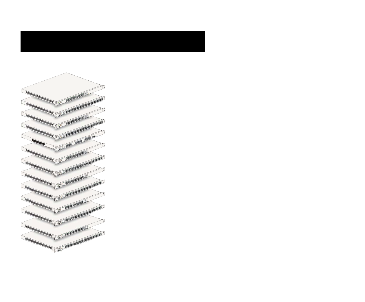
OmniSwitch 6850 Series
Features
OmniSwitch 6850-24L
OmniSwitch 6850-48L
OmniSwitch 6850-P24L
OmniSwitch 6850-P48L
OmniSwitch 6850-U24X
OmniSwitch 6850-24
OmniSwitch 6850-48
OmniSwitch 6850-24X
OmniSwitch 6850-48X
OmniSwitch 6850-P24
OmniSwitch 6850-P48
OmniSwitch 6850-P24X
OmniSwitch 6850-P48X
The OmniSwitch 6850 Series is an advanced fixed configuration family of Ethernet switches. These switches provide wire
rate Layer 2 forwarding and Layer 3 routing with advanced
services. All except OS6850-48X, OS6850-P48X, and
OS6850-U24X offer four combo ports consisting of four
shared 10/100/1000 ports and four 1000 Mbps fiber SFP ports.
• The OmniSwitch 6850-24L (OS6850-24L) is a
stackable edge/workgroup switch offering 20 unshared
10/100Base-T ports, as well as four combo ports individually configurable to be 10/100/1000Base-T or
1000Base-X high speed connections.
• The OmniSwitch 6850-48L (OS6850-48L) is a
stackable edge/workgroup switch offering 44 unshared
10/100Base-T ports, as well as four combo ports individually configurable to 10/100/1000Base-T or
1000Base-X high speed connections.
• The OmniSwitch 6850-P24L (OS6850-P24L) is a
stackable edge/workgroup switch offering 20 unshared
10/100Base-T PoE ports, as well as four combo ports
individually configurable to be 10/100/1000Base-T or
1000Base-X high speed connections.
• The OmniSwitch 6850-P48L (OS6850-P48L) is a
stackable edge/workgroup switch offering 44 unshared
October 2006 OmniSwitch 6850 Series 1
Page 8

10/100Base-T PoE ports, as well as four combo ports
individually configurable to 10/100/1000Base-T or
1000Base-X high speed connections.
• The OmniSwitch 6850-U24X (OS6850-U24X) is a
stackable edge/workgroup switch offering 24
1000Base-X MiniGBIC SFP ports, two (2) 10 Gigabit
XFP slots, as well as two combo ports individually
configurable to 10/100/1000Base-T ports.
• The OmniSwitch 6850-24 (OS6850-24) is a 24-port,
10/100/1000 fixed stackable chassis with four combo
fiber SFP ports.
• The OmniSwitch 6850-P24X (OS6850-P24X) is a 24-
port, 10/100/1000 PoE fixed stackable chassis with
four combo fiber SFP ports. This switch also includes
two 10-Gigabit XFP ports.
• The OmniSwitch 6850-P48X (OS6850-P48X) is a 48-
port, 10/100/1000 PoE fixed stackable chassis. This
switch also includes two 10-Gigabit XFP ports.
The OmniSwitch 6850 Series switches are based on the same
software architecture as OmniSwitch 9000 Series switches
(e.g., OS9700). They are designed to meet the most stringent
requirements for mission-critical networks.
• The OmniSwitch 6850-48 (OS6850-48) is a 48-port,
10/100/1000 fixed stackable chassis with four combo
fiber SFP ports.
• The OmniSwitch 6850-24X (OS6850-24X) is a 24-
port, 10/100/1000 fixed stackable chassis with four
combo fiber SFP ports. This switch also includes two
10-Gigabit XFP ports.
• The OmniSwitch 6850-48X (OS6850-48X) is a 48-
port, 10/100/1000 fixed stackable chassis. This switch
also includes two 10-Gigabit XFP ports.
• The OmniSwitch 6850-P24 (OS6850-P24) is a 24-port,
10/100/1000 PoE fixed stackable chassis with four
combo fiber SFP ports.
• The OmniSwitch 6850-P48 (OS6850-P48) is a 48-port,
10/100/1000 PoE fixed stackable chassis with four
combo fiber SFP ports.
2 OmniSwitch 6850 Series October 2006
Note. The 20 and 44 unshared 10/100Base-T PoE or nonPoE ports of the 24/48 Lite versions are software upgradeable to 10/100/1000BaseT ports. Please contact your
Alcatel representative for more information.
Stand-Alone and Stacked Configurations
Stand-Alone
A stand-alone OmniSwitch 6850 Series switch is ideal for
small and medium-sized network edge applications, offering
24 ports (OS6850-24, OS6850-24X, OS6850-P24,
OS6850-P24X, OS6850-24L, OS6850-P24L, OS6850-U24X)
and 48 ports (OS6850-48, OS6850-48X, OS6850-P48,
OS6850-P48X, OS6850-48L, OS6850-P48L) switches.
Page 9

These switches provide support for enterprise-based devices,
such as computer workstations or IP telephones.
A single OmniSwitch 6850 Series switch also supports 10Gigabit Ethernet uplinks for high-bandwidth connections to a
backbone or server.
the stack. This provides a virtual chassis with a 10/100/1000
capacity of up to 384 ports.
Note. Switches should be added one at a time in a stack.
Stacked Configurations
In addition to working as individual, stand-alone switches,
OmniSwitch 6850 Series switches can also be linked together
to form a single, high-density virtual chassis known as a stack.
Note. You cannot mix OS6800 and OS6850 switches in a
stack.
Stacking switches provides scalability by allowing users to
quickly and easily expand 10/100/1000 port density. Twentyfour 10/100/1000 ports are added for each OS6850-24,
OS6850-24X, OS6850-P24, OS6850-P24X, and
OS6850-U24X switch brought into the stack; forty-eight
10/100/1000 ports are added for each OS6850-48,
OS6850-48X, OS6850-P48, OS6850-P48X, and switch.
Twenty-four 10/100 ports are added for each OS6850-24L and
OS6850-P24L switch brought into the stack; forty-eight
10/100 ports are added for each OS6850-48L and
OS6850-P48L switch.
Up to eight switches can be stacked. OmniSwitch 6850 Series
switches can be mixed and matched in any combination within
As with the stand-alone configuration, a stacked virtual chassis configuration provides Gigabit Ethernet uplinks and 10Gigabit Ethernet uplinks to a backbone or server.
Network Applications
The OmniSwitch 6850 Series offers effective availability,
resiliency, and security features and are ideal for the following network applications:
• Enterprise workgroups/LAN wiring closets
• Edge deployments and branch offices
• L3 aggregation/distribution layer switches in three-tier
networks
• Small enterprise core switching
• Quality of Service (QoS) for mission critical applica-
tions
• Data center server clusters
October 2006 OmniSwitch 6850 Series 3
Page 10
Availability Features
Chassis Types
The switch provides a broad variety of availability features.
Availability features are hardware- and software-based safeguards that help to prevent the loss of data flow in the unlikely
event of a subsystem failure. In addition, some availability
features allow users to maintain or replace hardware components without powering off the switch or interrupting switch
operations. Combined, these features provide added resiliency
and help to ensure that the switch or virtual chassis is consistently available for day-to-day network operations.
Some key availability features include:
• Management Module Redundancy
• Software Rollback
• Backup Power Supplies
• Hot Swapping
• Hardware Monitoring
For information on these availability features, refer to the
OmniSwitch 6850 Series Hardware Users Guide.
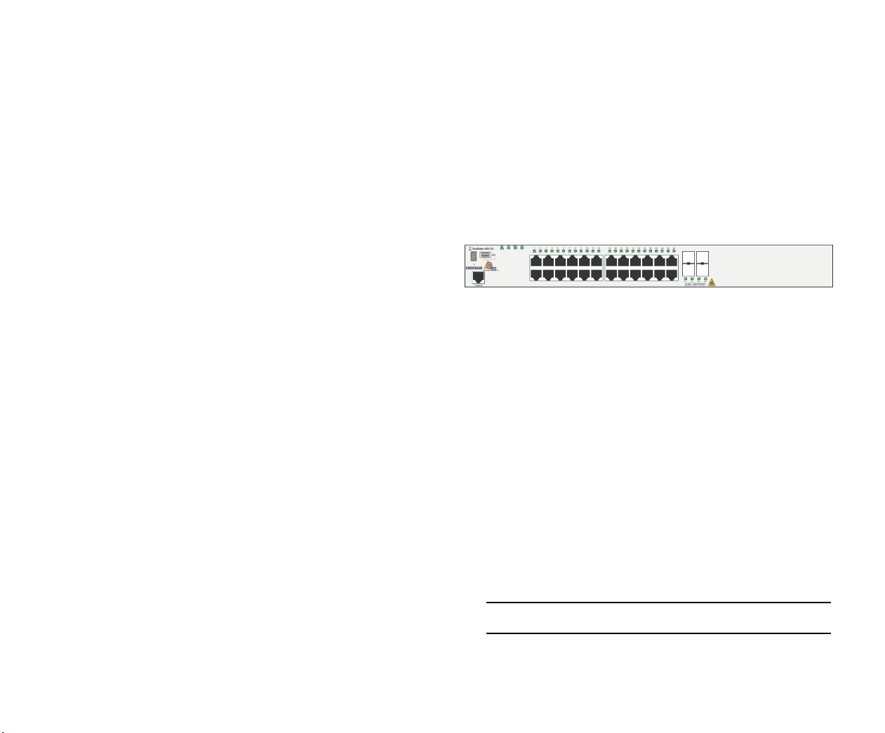
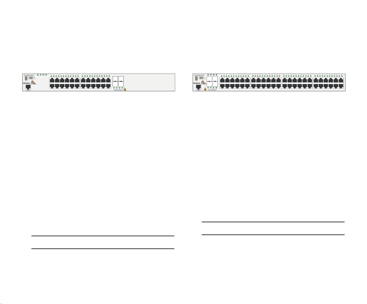
OmniSwitch 6850-24L (OS6850-24L)
The OmniSwitch 6850-24L is a stackable edge/workgroup
switch offering 20 unshared 10/100Base-T ports, as well as
four combo ports individually configurable to be
10/100/1000Base-T or 1000Base-X high speed connections.
The front panel of the OS6850-24L chassis contains the
following major components:
• System status and slot indicator LEDs
• (20) Unshared 10/100Base-T ports
• (4) Shared combo 10/100/1000Base-T ports
• (4) Combo SFP slots for 1000Base-X connections
• Console port (RJ-45)
• USB port (USB 2.0)
For more information on the OS6850-24L chassis details, refer
to “Hardware Basics” on page 57.
Note. USB 2.0 is not supported in this release.
4 OmniSwitch 6850 Series October 2006
Page 11
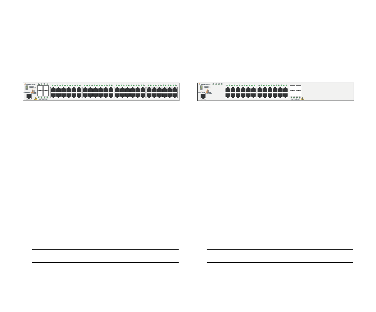
OmniSwitch 6850-48L (OS6850-48L)
OmniSwitch 6850-P24L (OS6850-P24L)
The OmniSwitch 6850-48L is a stackable edge/workgroup
switch offering 44 unshared 10/100Base-T ports, as well as
four combo ports individually configurable to
10/100/1000Base-T or 1000Base-X high speed connections.
The front panel of the OS6850-48L chassis contains the
following major components:
• System status and slot indicator LEDs
• (44) Unshared 10/100Base-T ports
• (4) Shared combo 10/100/1000Base-T ports
• (4) Combo SFP slots for 1000Base-X connections
• Console port (RJ-45)
• USB port (USB 2.0)
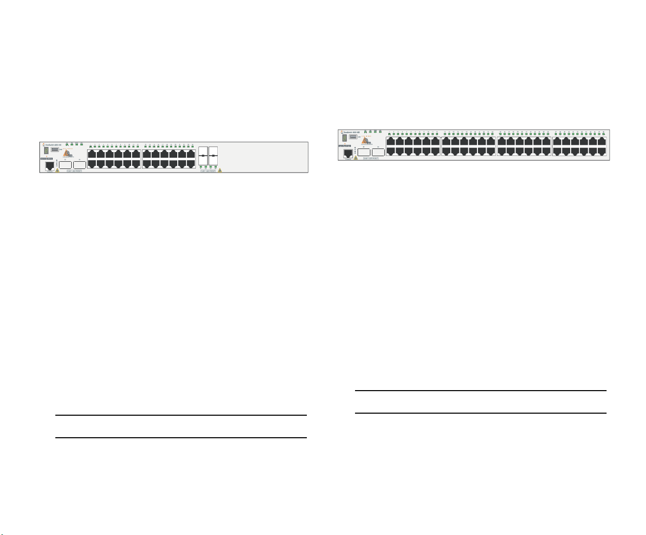
The OmniSwitch 6850-P24L is a stackable edge/workgroup
switch offering 20 unshared 10/100Base-T PoE ports, as well
as four combo ports individually configurable to be
10/100/1000Base-T or 1000Base-X high speed connections.
The front panel of the OS6850-P24L chassis contains the
following major components:
• System status and slot indicator LEDs
• (20) Unshared 10/100Base-T PoE ports
• (4) Shared combo 10/100/1000Base-T PoE ports
• (4) Combo SFP slots for 1000Base-X connections
• Console port (RJ-45)
• USB port (USB 2.0)
For more information on the OS6850-48L chassis details, refer
to “Hardware Basics” on page 57.
Note. USB 2.0 is not supported in this release.
October 2006 OmniSwitch 6850 Series 5
For more information on the OS6850-P24L chassis details,
refer to “Hardware Basics” on page 57.
Note. USB 2.0 is not supported in this release.
Page 12
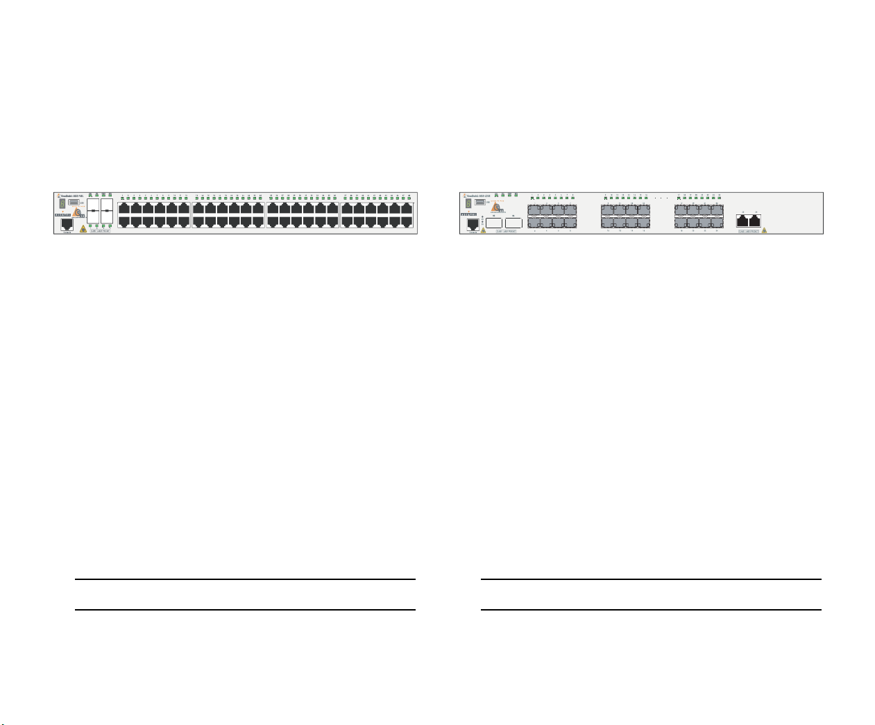
OmniSwitch 6850-P48L (OS6850-P48L)
OmniSwitch 6850-U24X (OS6850-U24X)
The OmniSwitch 6850-P48L is a stackable edge/workgroup
switch offering 44 unshared 10/100Base-T PoE ports, as well
as four combo ports individually configurable to
10/100/1000Base-T or 1000Base-X high speed connections.
The front panel of the OS6850-P48L chassis contains the
following major components:
• System status and slot indicator LEDs
• (44) Unshared 10/100Base-T PoE ports
• (4) Shared combo 10/100/1000Base-T PoE ports
• (4) Combo SFP slots for 1000Base-X connections
• Console port (RJ-45)
• USB port (USB 2.0)
The OmniSwitch 6850-U24X is a stackable edge/workgroup
switch offering 24 1000Base-X MiniGBIC SFP ports, two (2)
10 Gigabit XFP slots, as well as two combo ports individually
configurable to 10/100/1000Base-T ports.
The front panel of the OS6850-U24X chassis contains the
following major components:
• System status and slot indicator LEDs
• (22) Unshared 1000Base-X MiniGBIC SFP ports
• (2) Shared combo 1000Base-X MiniGBIC SFP ports
• (2) Combo RJ-45 10/100/1000Base-T ports
• (2) 10 Gigabit XFP slots
• Console port (RJ-45)
• USB port (USB 2.0)
For more information on the OS6850-P48L chassis details,
refer to “Hardware Basics” on page 57.
Note. USB 2.0 is not supported in this release.
6 OmniSwitch 6850 Series October 2006
For more information on the OS6850-U24X chassis details,
refer to “Hardware Basics” on page 57.
Note. USB 2.0 is not supported in this release.
Page 13
OmniSwitch 6850-24 (OS6850-24)
OmniSwitch 6850-48 (OS6850-48)
The OmniSwitch 6850-24 is a stackable edge/workgroup
switch offering 24 10/100/1000Base-T ports, as well as four
SFP ports for high-speed connections.
The front panel of the OS6850-24 chassis contains the following major components:
• System status and slot indicator LEDs
• (20) Unshared 10/100/1000Base-T ports
• (4) Shared combo 10/100/1000Base-T ports
• (4) Combo SFP slots for 1000Base-X connections
• Console port (RJ-45)
• USB port (USB 2.0)
For more information on the OS6850-24 chassis details, refer
to “Hardware Basics” on page 57.
The OmniSwitch 6850-48 is a stackable edge/workgroup
switch offering 48 10/100/1000Base-T ports, as well as four
SFP ports for high-speed connections.
The front panel of the OS6850-48 chassis contains the following major components:
• System status and slot indicator LEDs
• (44) Non-combo 10/100/1000Base-T ports
• (4) Combo 10/100/1000Base-T ports
• (4) Combo SFP slots for 1000Base-X connections
• Console port (RJ-45)
For more information on the OS6850-48 chassis details, refer
to “Hardware Basics” on page 57.
Note. USB 2.0 is not supported in this release.
Note. USB 2.0 is not supported in this release.
October 2006 OmniSwitch 6850 Series 7
Page 14
OmniSwitch 6850-24X (OS6850-24X)
OmniSwitch 6850-48X (OS6850-48X)
The OmniSwitch 6850-P24X is a stackable edge/workgroup
switch offering 24 10/100/1000Base-T ports, as well as four
SFP ports for high-speed connections. This switch also
includes two 10-Gigabit XFP ports.
The front panel of the OS6850-24X chassis contains the
following major components:
• System status and slot indicator LEDs
• (20) Unshared 10/100/1000Base-T ports
• (4) Shared combo 10/100/1000Base-T ports
• (4) Combo SFP slots for 1000Base-X connections
• (2) 10-Gigabit XFP slots
• Console port (RJ-45)
• USB port (USB 2.0)
For more information on the OS6850-24X chassis details,
refer to “Hardware Basics” on page 57.
The OmniSwitch 6850-48X is a stackable edge/workgroup
switch offering 48 10/100/1000Base-T ports.This switch also
includes two 10-Gigabit XFP ports.
The front panel of the OS6850-48X chassis contains the
following major components:
• System status and slot indicator LEDs
• (48) Unshared 10/100/1000Base-T ports
• (2) 10-Gigabit XFP slots
• Console port (RJ-45)
• USB port (USB 2.0)
For more information on the OS6850-48X chassis details,
refer to “Hardware Basics” on page 57.
Note. USB 2.0 is not supported in this release.
Note. USB 2.0 is not supported in this release.
8 OmniSwitch 6850 Series October 2006
Page 15
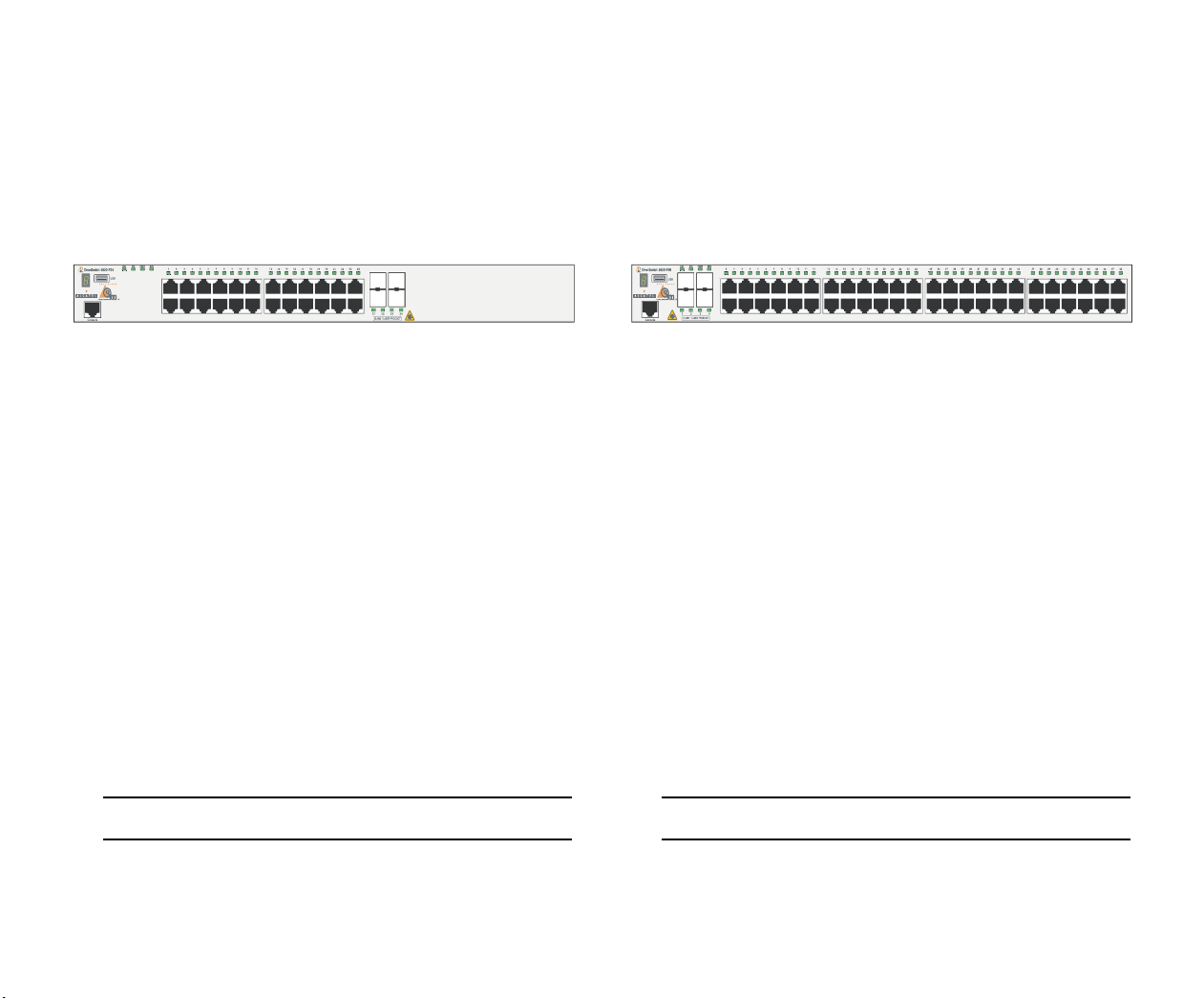
OmniSwitch 6850-P24 (OS6850-P24)
OmniSwitch 6850-P48 (OS6850-P48)
The OmniSwitch 6850-P24 is a stackable edge/workgroup
switch offering 24 Power over Ethernet (PoE)
10/100/1000Base-T ports, as well as four SFP ports for highspeed connections.
The front panel of the OS6850-P24 chassis contains the
following major components:
• System status and slot indicator LEDs
• (20) Unshared 10/100/1000Base-T PoE ports
• (4) Shared combo 10/100/1000Base-T PoE ports
• (4) Combo SFP slots for 1000Base-X connections
• Console port (RJ-45)
• USB port (USB 2.0)
The OmniSwitch 6850-P48 is a stackable edge/workgroup
switch offering 48 Power over Ethernet (PoE)
10/100/1000Base-T ports, as well as four SFP ports for highspeed connections.
The front panel of the OS6850-P48 chassis contains the
following major components:
• System status and slot indicator LEDs
• (44) Unshared 10/100/1000Base-T PoE ports
• (4) Shared combo 10/100/1000Base-T PoE ports
• (4) Combo SFP slots for 1000Base-X connections
• Console port (RJ-45)
• USB port (USB 2.0)
For more information on the OS6850-P24 chassis details, refer
to “Hardware Basics” on page 57.
Note. USB 2.0 is not supported in this release.
October 2006 OmniSwitch 6850 Series 9
For more information on the OS6850-P48 chassis details, refer
to “Hardware Basics” on page 57.
Note. USB is not supported in this release.
Page 16
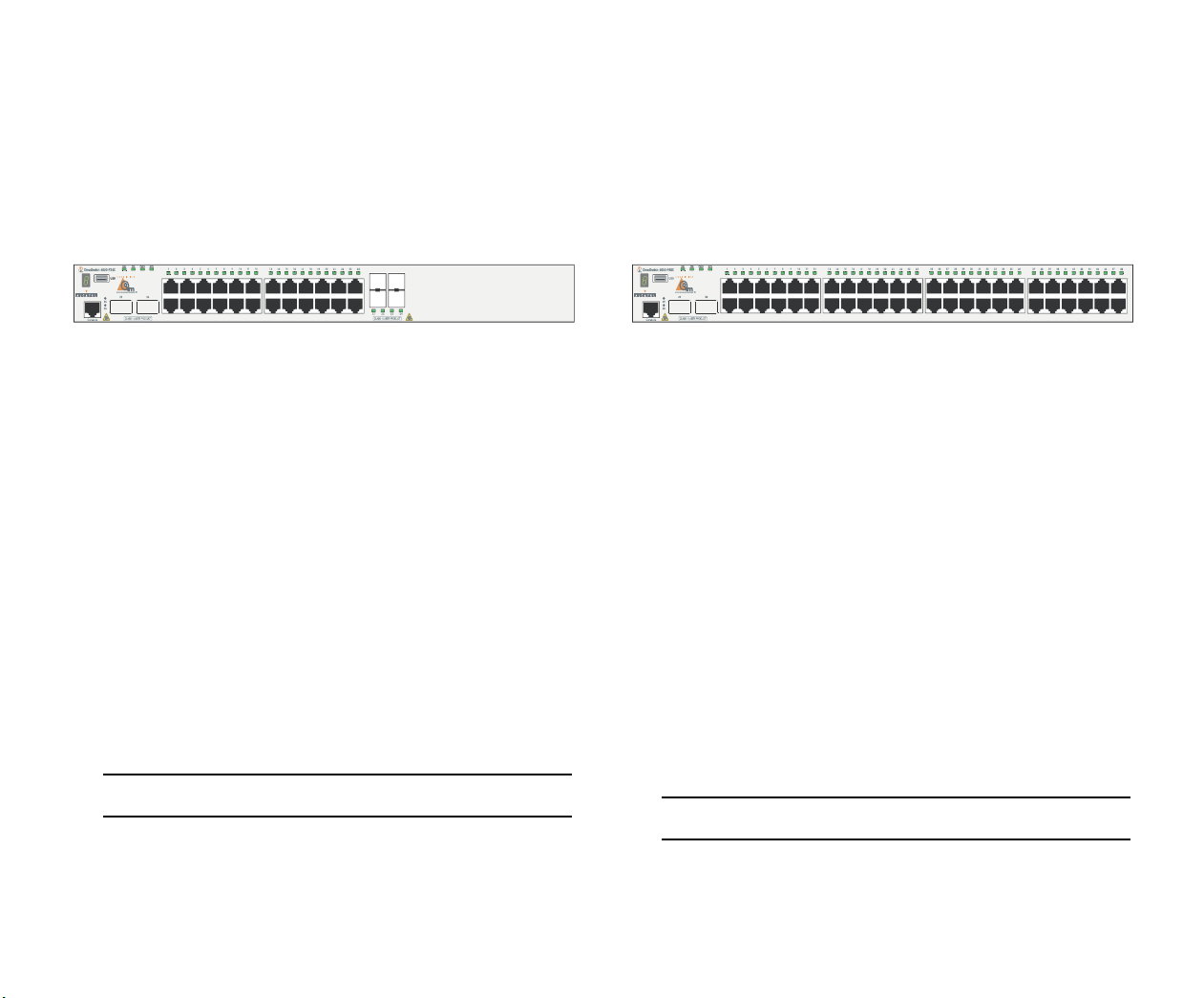
OmniSwitch 6850-P24X (OS6850-P24X)
OmniSwitch 6850-P48X (OS6850-P48X)
The OmniSwitch 6850-P24X is a stackable edge/workgroup
switch offering 24 Power over Ethernet (PoE)
10/100/1000Base-T ports, as well as four SFP and two XFP
ports for high-speed connections.
The front panel of the OS6850-P24X chassis contains the
following major components:
• System status and slot indicator LEDs
• (20) Unshared 10/100/1000Base-T PoE ports
• (4) Shared combo 10/100/1000Base-T PoE ports
• (4) Combo SFP slots for 1000Base-X connections
• (2) 10-Gigabit XFP slots
• Console port (RJ-45)
• USB port (USB 2.0)
For more information on the OS6850-P24X chassis details,
refer to “Hardware Basics” on page 57.
The OmniSwitch 6850-P48X is a stackable edge/workgroup
switch offering 48 Power over Ethernet (PoE)
10/100/1000Base-T ports, as well as four SFP and two XFP
ports for high-speed connections.
The front panel of the OS6850-P48X chassis contains the
following major components:
• System status and slot indicator LEDs
• (48) Unshared 10/100/1000Base-T PoE ports
• (4) Combo SFP slots for 1000Base-X connections
• (2) 10-Gigabit XFP slots
• Console port (RJ-45)
• USB port (USB 2.0)
For more information on the OS6850-P48X chassis details,
refer to “Hardware Basics” on page 57.
Note. USB 2.0 is not supported in this release.
Note. USB 2.0 is not supported in this release.
10 OmniSwitch 6850 Series October 2006
Page 17

Note. The 20 and 44 unshared 10/100Base-T PoE or nonPoE ports of the 24/48 Lite versions are software upgradeable to 10/100/1000BaseT ports. Please contact your
Alcatel representative for more information.
Power Supplies
OmniSwitch 6850 Series switches support power supply
components. The components include:
• PS-120W-DC backup power supply module
• PS-126W-AC backup power supply module
• PS-360W-AC backup power supply module
• PS-510W-AC backup power supply module
• Backup power supply connector cable
When backup power supply components are installed, the
primary (factory-installed) power supply continues to take on
the full power load for switch operations. Meanwhile, the
backup power supply operates in active standby mode. If the
primary power supply fails unexpectedly, the backup power
supply automatically takes up the full power load without
disrupting the switch.
.
The OmniSwitch 6850 Series backup power supply system is
chassis-based with each chassis supporting up to eight backup
power supplies. This provides 1:1 redundancy for stacks of up
to eight switches
October 2006 OmniSwitch 6850 Series 11
Page 18

Setting Up the Hardware
Items Required
In addition to the materials and components provided in the
OmniSwitch 6850 Series shipment, you must provide the
following items in order to complete this installation:
• Grounding wrist strap
• Phillips screwdriver
• Serial cable
• Rack mount screws, if applicable
Site Preparation
Environmental Requirements
OmniSwitch 6850 Series switches have the following environmental and airflow requirements:
• The installation site must maintain a temperature
between 0° and 45° Celsius (32° and 113° Fahrenheit)
and not exceed 95 percent maximum humidity (noncondensing) at any time.
• Be sure to allow adequate room for proper air ventila-
tion and access at the front, back, and sides of the
switch. No clearance is necessary at the top or bottom
of the chassis. Refer to page 16 for minimum clearance requirements.
Electrical Requirements
OmniSwitch 6850 Series switches have the following general
electrical requirements:
• Each switch requires one grounded AC power source.
• Grounded AC power source must be 110V for North
American installations (220V international).
• Each supplied AC power cord is approximately 2
meters (6.5 feet) long. Do not use extension cords.
Weight Considerations
OS6850-24L
A single OS6850-24L weighs approximately 14 lbs (6.24
Kgs). A stack of eight OS6850-24L switches weighs approximately 112 lbs (50 Kgs).
OS6850-48L
A single OS6850-48L weighs approximately 14 lbs (6.24
Kgs). A stack of eight OS6850-48L switches weighs approximately 112 lbs (50 Kgs).
12 Setting Up the Hardware October 2006
Page 19

OS6850-P24L
OS6850-24X
A single OS6850-P24L weighs approximately 14 lbs (6.24
Kgs). A stack of eight OS6850-P24L switches weighs approximately 112 lbs (50 Kgs).
OS6850-P48L
A single OS6850-P48L weighs approximately 14 lbs (6.24
Kgs). A stack of eight OS6850-P48L switches weighs approximately 112 lbs (50 Kgs).
OS6850-U24X
A single OS6850-U24X weighs approximately 14 lbs (6.24
Kgs). A stack of eight OS6850-U24X switches weighs approximately 112 lbs (50 Kgs).
OS6850-24
A single OS6850-24 weighs approximately 14 lbs (6.24 Kgs).
A stack of eight OS6850-24 switches weighs approximately
112 lbs (50 Kgs).
OS6850-48
A single OS6850-48 weighs approximately 14 lbs
(6.24 Kgs). A stack of eight OS6850-48 switches weighs
approximately 112 lbs (50 Kgs).
A single OS6850-24X weighs approximately 14 lbs (6.24
Kgs). A stack of eight OS6850-24X switches weighs approximately 112 lbs (50 Kgs).
OS6850-48X
A single OS6850-48X weighs approximately 14 lbs (6.24
Kgs). A stack of eight OS6850-48X switches weighs approximately 112 lbs (50 Kgs).
OS6850-P24
A single OS6850-P24 weighs approximately 14 lbs (6.24
Kgs). A stack of eight OS6850-P24 switches weighs approximately 112 lbs (50 Kgs).
OS6850-P48
A single OS6850-P48 weighs approximately 14 lbs
(6.24 Kgs). A stack of eight OS6850-P48 switches weighs
approximately 112 lbs (50 Kgs).
OS6850-P24X
A single OS6850-P24X weighs approximately 14 lbs (6.24
Kgs). A stack of eight OS6850-P24X switches weighs approximately 112 lbs (50 Kgs).
October 2006 Setting Up the Hardware 13
Page 20

OS6850-P48X
A single OS6850-P48X weighs approximately 14 lbs
(6.24 Kgs). A stack of eight OS6850-P48X switches weighs
approximately 112 lbs (50 Kgs).
Items Included
Your OmniSwitch 6850 Series switch order includes the
following items:
• OmniSwitch 6850 Series chassis
• Rack mount flanges with attachment screws (rack
mount flanges may be pre-installed on some orders)
• Power cord (country-specific)
• OmniSwitch 6850 Series-specific user documentation:
OmniSwitch 6850 Series Getting Started Guide
OmniSwitch 6850 Series Hardware Users Guide
OmniSwitch CLI Reference Guide
Depending on the items ordered for your specific network
requirements, the following optional items may also be
included:
• Stacking cables (per order)
• Combo port SFPs (per order)
• 10-Gigabit XFPs (per order)
• Backup power supply components and cables
(per order)
OmniSwitch 6800/6850/9000 Switch Management
Guide
OmniSwitch 6800/6850/9000 Network Configuration
Guide
OmniSwitch 6800/6850/9000 Advanced Routing
Configuration Guide
14 Setting Up the Hardware October 2006
Page 21

Unpacking and Initial Setup
Unpacking the Chassis
To protect your OmniSwitch chassis and hardware components from electrostatic discharge (ESD) and physical damage,
read all unpacking recommendations and instructions carefully before beginning.
Recommendations
• Unpack your OmniSwitch chassis as close as possible
to the location where it will be installed.
4 Carefully remove any foam pads and protective plastic
from the switch chassis.
Note. Alcatel provides factory-installed blank cover plates
for empty backup power supply or 10-Gigabit expansion
module bays. Do not remove these cover plates unless a
backup power supply or expansion module is to be
installed immediately at the corresponding bay.
5 If you are installing multiple switches in a stacked
configuration, repeat steps 1 through 4 for the remaining
switches that will make up the stack.
• Depending on your order, Small Form-Factor Plugga-
bles (SFPs), stacking cables and backup power supply
components may be packaged separately. In order to
6 Once all OmniSwitch 6850 Series switches have been
removed from their packaging, continue to “Setting Up
the Switch.”
greatly reduce exposure to electrostatic discharge
(ESD) and physical damage, do not unpack these items
until they are ready to be installed.
Instructions
1 Carefully cut the tape along the seam at the top of the
box containing the chassis.
2 Lift the box’s top flaps. Remove any smaller boxes or
pouches that are enclosed and set them aside.
3 Lift the chassis out of the packaging.
October 2006 Setting Up the Hardware 15
Page 22
Setting Up the Switch
Never obstruct the air vents located at the left and right sides
of the chassis.
Note. Due to their airflow and access requirements,
OmniSwitch 6850 Series switches cannot be wallmounted.
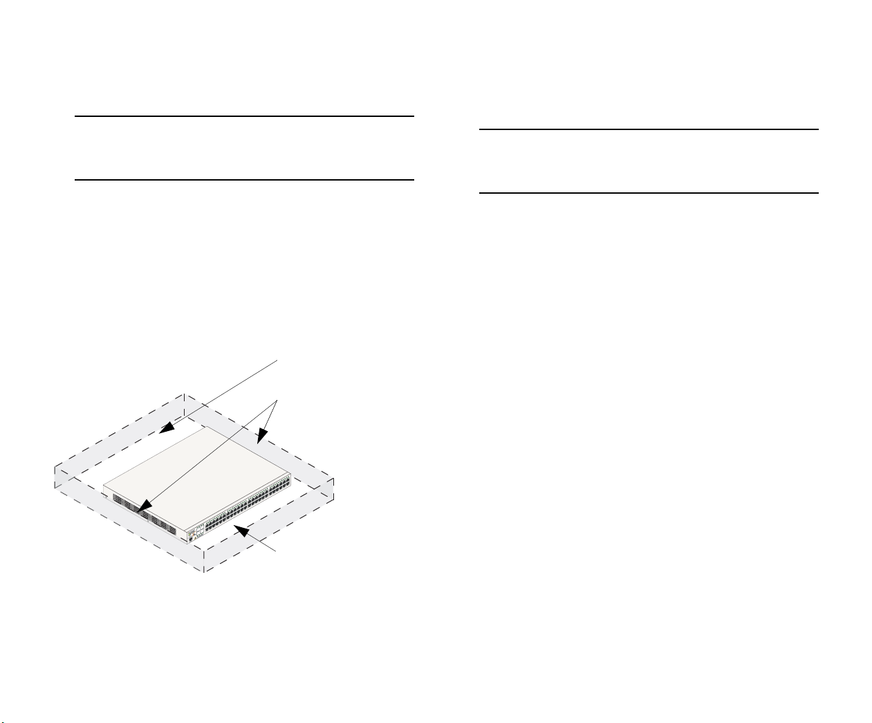
Airflow Considerations
Be sure that your switch is placed in a well-ventilated, staticfree environment. Always allow adequate clearance at the
front, rear, and sides of the switch.
The following diagram shows recommended minimum clearances for adequate chassis airflow and access to components at
the rear of the chassis.
Rear. 5 inches minimum
at rear of chassis.
Sides. 2 inches minimum
at left and right sides for
chassis airflow.
Note. Clearance is not required at the top and bottom of
the chassis. For detailed chassis airflow diagrams, refer to
the OmniSwitch 6850 Series Hardware Users Guide.
Installation Options
There are two ways in which the OmniSwitch 6850 Series
switches can be installed:
• Tabletop installation
• Rack-mount installation
For information on setting up a switch as a tabletop unit, refer
to “Installing the Switch on a Tabletop or Bench.” For information on rack-mounting the switch, refer to
“Rack-Mounting the Switch” on page 18.
Front. 6 inches minimum
at front of chassis for
cable access and LED
visibility.
Chassis Top View
16 Setting Up the Hardware October 2006
Page 23

Installing the Switch on a Tabletop or Bench
OmniSwitch 6850 Series switches can be installed freestanding as tabletop units. Place your switch on a stable, flat, and
static-free surface.
Note. OmniSwitch 6850 Series switches must be placed
“right side up.” Never attempt to operate a switch positioned on its side.
Tabletop Mounting Steps
To install the switch as a tabletop unit, follow the steps below:
1 Position the chassis on the table or bench where it is to
be installed.
2 Be sure that adequate clearance has been provided for
chassis airflow and access to the front, back, and sides of
the switch. For recommended clearances, refer to page 16.
Also, be sure that you have placed the chassis within reach
of all required AC power sources.
Note. If you are installing a single (i.e., stand-alone)
switch, continue to “Connections and Cabling” on page 24
for additional setup procedures.
If you are placing multiple switches in a stacked configuration, carefully stack the remaining switches, one on top
of the other. Up to eight switches may be stacked to form
a single virtual chassis. Be sure to maintain adequate
clearance at the front, rear, left, and right side of all
switches (see page 16). Also, be sure that you have placed
all switches in the stack within reach of required AC
power sources.
October 2006 Setting Up the Hardware 17
Page 24
Rack-Mounting the Switch
Refer to the important guidelines below before installing the
OmniSwitch chassis in a rack.
• Review page 16 for important chassis airflow and
access recommendations before installing.
Rack Mounting Steps
• It is recommended that two people install the switch in
the rack—one person to hold the chassis and position it
in the rack, and a second person to secure the chassis to
the rack using attachment screws (not supplied).
• Alcatel provides two rack-mount flanges with each
OmniSwitch 6850 Series switch. These flanges support
standard 19-inch rack mount installations. These
flanges must be attached to the chassis before the
switch can be rack mounted.
Note. If you are installing the switch in a 23-inch wide
rack, Alcatel offers optional 23-inch rack-mounting hardware. For more information, contact your Alcatel representative.
• Alcatel does not provide rack-mount screws. Use the
screws supplied by the rack vendor.
• To prevent a rack from becoming top heavy, it is
recommended that you install heavier equipment at the
bottom of the rack whenever possible.
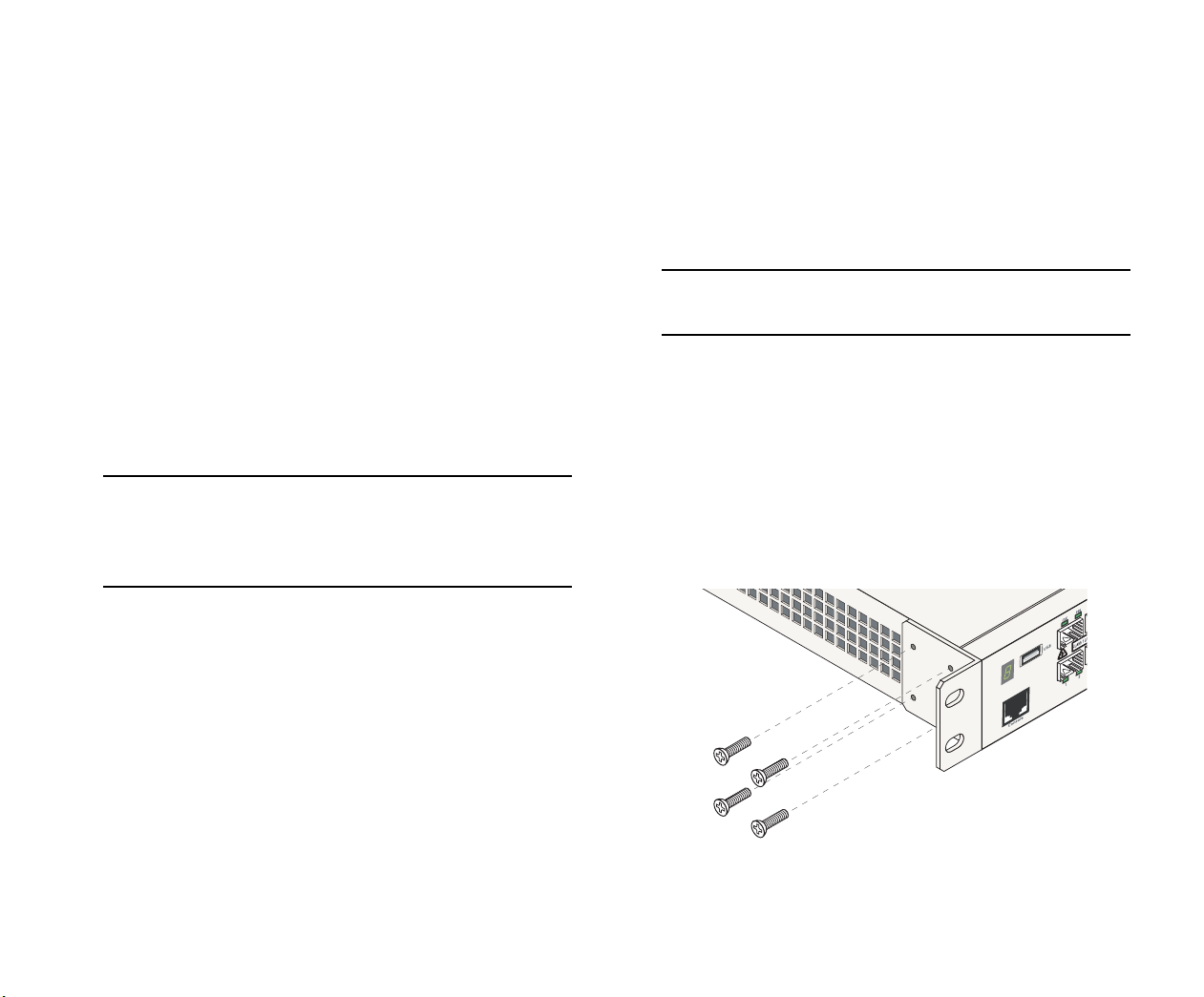
To rack-mount the switch, follow the steps below.
Note. Rack-mount flanges may come factory-installed in
some cases. If this is the case, skip steps 1 and 2 below.
1 Align the holes in the provided rack-mount flanges
with the four threaded holes in the OmniSwitch chassis.
These threaded holes are located in the left and right sides
of the chassis, near the front panel.
2 Attach the flanges to the chassis using the provided
Phillips-head screws. Be sure to tighten each of the screws
firmly using a Phillips screwdriver.
45
46
Console
• If you are installing the switch in a relay rack, be sure
to install and secure the rack as per the rack manufacturer’s specifications.
Attaching a Rack-Mount Flange
18 Setting Up the Hardware October 2006
Page 25

3 After the rack-mount flanges are secured to the chas-
sis, mark the holes on the rack where the switch is to be
installed.
7 Once the screws at the bottom of each flange are
secure, install the remaining two rack-mount screws. Be
sure that all screws are securely tightened.
4 Lift and position the switch until the rack-mount
flanges are flush with the rack post.
5 Align the holes in the flanges with the rack holes that
were marked in step 3.
6 Once the holes are aligned, insert a rack-mount screw
(not provided) through the bottom hole of each flange.
Tighten both screws until they are secure.
Attaching the Switch to the Rack
8 If you are installing multiple switches in a rack to form
a stacked configuration, repeat steps 1 through 7 for all
switches in the stack.
Note. When rack mounting multiple switches in a stacked
configuration, be sure to place all switches in vertically-
adjacent rack positions. This will ensure that all required
stacking cables will have adequate length for the installa-
tion.
Note. Be sure to install the screws in the bottom hole of
each flange, as shown, before proceeding.
October 2006 Setting Up the Hardware 19
Page 26

Installing Combo Port SFPs
OmniSwitch 6850 Series switches offer Gigabit Ethernet
combo ports, located on the front panel (see page 64). These
combo ports support hot-swappable fiber Small Form-Factor
Pluggables (SFPs). For instructions on installing and removing combo port SFPs, refer to the instruction card provided
with the SFP product.
Note. Combo port preferences are user-configurable via
the system software. Refer to the “Configuring Ethernet
Ports” in the OmniSwitch 6800/6850/9000 Network
Configuration Guide for complete details.
Note. For further details regarding supported SFP and
XFP transceivers, refer to the OmniSwitch 6850 Series
Hardware Users Guide.
Installing Backup Power Supply Components
For detailed information on installing backup power supply
components—including the backup power supply, connector
cables, and power cords—refer to the OmniSwitch 6850 Series
Hardware Users Guide.
20 Setting Up the Hardware October 2006
Page 27

Completing a Stacked Configuration
Cabling Stacked Configurations
In order to connect stacked switches into a virtual chassis, all
modules in the stack must be connected via stacking cables
(provided).
Redundant Stacking Cable Connections
In addition to the stacking cables installed between adjacent
switch, the top-most switch and bottom-most switch in the
stack must be connected using a redundant stacking cable.
Refer to the OmniSwitch 6850 Series Hardware Users Guide
for more information on the redundant stacking cable connection.
Supported Cabling Patterns
Each switch provides two stacking ports: stacking port A and
stacking port B. Cables can be connected in any pattern. In
other words, the cable connected to stacking port A of one
switch can be connected to either stacking port A or stacking
port B of the adjacent switch. However, it is strongly recommended that the cabling pattern remains consistent across the
stack. For a cabling diagram and additional information on
cabling the stack, refer to the OmniSwitch 6850 Series Hardware Users Guide.
Cabling Steps
1 Before inserting a stacking cable into one of the stack-
ing ports, be sure to orient the stacking cable connector
properly. The wide portion of the connector must be
facing up. Refer to the diagram below for more informa-
tion.
Connector Top
End View of Stacking Cable Connector
2 Starting from the top of the stack, insert one end of the
stacking cable into either stacking port A or stacking port
B. The stacking port (A or B) depends on your preferred
cabling pattern. Refer to the OmniSwitch 6850 Series
Hardware Users Guide for detailed information on cabling
patterns. Be sure that cable connector is completely
inserted and fully seated in the chassis.
3 Insert the other end of the stacking cable into the stack-
ing port of the switch immediately below. Once again, the
stacking port (A or B) depends on the preferred cabling
pattern.
When orienting the stacking cable connector, be sure that the wider portion of the
connector is facing up, as shown. Otherwise, the stacking cable will not fit properly
in the chassis’ stacking port.
October 2006 Completing a Stacked Configuration 21
Page 28

4 Repeat this procedure until all switches in the stack are
connected (see illustrations a, b, and c below).
Reminder. The diagram below shows one supported
stacking cable pattern. For additional supported cabling
patterns, refer to the OmniSwitch 6850 Series Hardware
Users Guide.
5 To provide added resiliency and redundancy, you must
install the redundant stacking cable to connect the top
switch in the stack to the bottom switch. Connect the
redundant cable now. Refer to the diagram below for more
information
a
Connecting the Switches in the Stack
22 Completing a Stacked Configuration October 2006
b
c
Redundant Connection Between Top and Bottom Switches
6 Once all stacking cable connectors are inserted, tighten
the captive screws at the left- and right-hand sides of each
connector, as shown. Be sure not to overtighten the
screws.
Page 29

Tightening Stacking Connector Captive Screws
7 Now that all switches in the stack are connected, the
next step is to connect all required network and management cables. Refer to “Connections and Cabling” on
page 24 for more information.
October 2006 Completing a Stacked Configuration 23
Page 30

Connections and Cabling
Once your switch is properly set up and all the required hardware components are installed, you should connect all network
and management cables required for your network applications. Connections may include:
• RJ-45 cable connection to the console port
• Single mode or multimode fiber cables to combo port
SFPs as required by your network
• Ethernet cables to 10/100/1000 or 10/100 Ethernet
ports as required by your network
Connecting the Serial Cable
The console port, located on the chassis front panel, provides a
serial connection to the switch and is required when logging
into the switch for the first time. By default, this RJ-45
connector provides a DTE console connection.
Serial Connection Default Settings
The default settings for the serial connection are as follows:
baud rate 9600
parity none
data bits (word size) 8
stop bits 1
Note. For information on modifying these settings, refer to
the OmniSwitch 6850 Series Hardware Users Guide.
24 Connections and Cabling October 2006
Page 31

Booting OmniSwitch 6850 Series Switches
Booting a Stand-alone Switch
The OmniSwitch 6850 Series switch does not use an on/off
switch. The power cord is the switch’s only connect/disconnect device. The power connector socket is located on the
switch’s rear panel. For more information, refer to
“OmniSwitch 6850 Series Rear Panel” on page 72.
To boot the switch, plug the power cord (provided) into the
power connector socket at the switch’s rear panel. Next, plug
the power cord into an easily-accessible power source, such as
a grounded AC outlet or an Uninterruptible Power Supply
(UPS).
The switch immediately begins the boot process. Allow a few
moments for the switch to boot completely, then verify the
status of all LEDs on the switch’s front panel. A successful
boot for a stand-alone switch displays the following LED
states:
LED States for a Stand-alone Switch
OK Solid green
PRI Solid green
LED States for a Stand-alone Switch
BPS Solid amber, if BPS attached is failed;
off, if no operational BPS is attached;
solid green if an operational BPS is
attached and operating normally. See
page 71 for more information.
XFP1 Off (applies to all OmniSwitch 6850
Series switches except for the
OmniSwitch 6850-24X,
OmniSwitch 6850-P24X,
OmniSwitch 6850-48X,
OmniSwitch 6850-P48X, and
OmniSwitch 6850-U24X).
XFP2 Off (applies to all OmniSwitch 6850
Series switches except for the
OmniSwitch 6850-24X,
OmniSwitch 6850-P24X,
OmniSwitch 6850-48X,
OmniSwitch 6850-P48X, and
OmniSwitch 6850-U24X).
PWR Solid green
October 2006 Booting OmniSwitch 6850 Series Switches 25
Page 32

LED States for a Stand-alone Switch
Slot Indicator 1–8 (non-blinking), depending on the
slot number value in the boot.slot.cfg
file. See the OmniSwitch 6850 Series
Hardware Users Guide for detailed
information. The default value is 1.
If any of the LED state differs from the states shown in the
table above, refer to page 71 for more information. Contact
Alcatel Customer Support if the unexpected LED state
persists.
Important. Be sure to power on all switches in the stack
in rapid succession; otherwise, switches may be assigned
unintended stack management roles. Refer to the
OmniSwitch 6850 Series Hardware Users Guide for
detailed information.
The stack immediately begins the boot process. Allow a few
moments for all elements in the stack to boot completely, then
verify the status of all LEDs on the switch’s front panel.
A successful boot for a stacked configuration displays the
following LED states.
Booting Stacked Configurations
Once the switches have been connected into a virtual chassis
and the network cables have been attached, the next step is to
manually power on the stack. The OmniSwitch 6850 Series
switch does not use an on/off switch. The power cord is the
switch’s only connect/disconnect device. The power connector socket is located on the switch’s rear panel. For more information, refer to “OmniSwitch 6850 Series Rear Panel” on
page 72.
To boot the stack, plug the power cord (provided) into the
power connector socket at the rear panel of each switch in the
stack. Next, plug all power cords, in rapid succession, into
easily-accessible power sources, such as grounded AC outlets
or an Uninterruptible Power Supply (UPS).
26 Booting OmniSwitch 6850 Series Switches October 2006
LED States for a Stacked Configuration
OK Solid green for all switches.
PRI Solid green for the primary manage-
ment module; solid amber for the secondary management module; off for
switches operating in idle roles.
Detailed information for primary, secondary, and idle roles is provided in
the OmniSwitch 6850 Series Hard-
ware Users Guide.
PWR Solid green for all switches.
BPS Solid amber, if BPS attached is failed;
off, when no operational BPS is
attached; solid green if an operational
BPS is attached and operating normally. See page 71 for more information.
Page 33

LED States for a Stacked Configuration
Management Role Assignment
XFP1 Off (applies to all OmniSwitch 6850
Series switches except for the
OmniSwitch 6850-24X,
OmniSwitch 6850-P24X,
OmniSwitch 6850-48X,
OmniSwitch 6850-P48X, and
OmniSwitch 6850-U24X).
XFP2 Off (applies to all OmniSwitch 6850
Series switches except for the
OmniSwitch 6850-24X,
OmniSwitch 6850-P24X,
OmniSwitch 6850-48X,
OmniSwitch 6850-P48X, and
OmniSwitch 6850-U24X).
Slot Indicator 1–8 (non-blinking), depending on the
slot number assignment for each corresponding switch. See the
OmniSwitch 6850 Series Hardware
Users Guide for detailed information.
If any of the LED state differs from the states shown in the
table above, refer to page 71 for more information. Contact
Alcatel Customer Support if the unexpected LED state
persists.
When a stack of OmniSwitch 6850 Series switches boots, the
system software automatically detects the switch in the stack
with the lowest MAC address. This switch is assigned the
primary management role and, by default, is given the slot
number 1. The module connected to the primary’s stacking
port A is automatically assigned the secondary management
role and given the slot number 2.
As the other modules in the stack become operational, they are
assigned idle roles and are automatically assigned unique slot
numbers (3–8, depending on the number of switches in the
stack). The slot numbering for idle modules is determined by
each module’s physical location in the stack.
Note. As the slot numbers are dynamically assigned,
boot.slot.cfg files are auto-generated in the /flash direc-
tory of each switch. When the stack is subsequently
booted, each switch reads its slot number assignment from
this file and comes up accordingly.
In the example below, the fourth switch from the top is elected
the primary management module for the stack. (It can be
assumed that this switch has the lowest MAC address in the
stack.) This switch is automatically assigned slot number 1.
Dynamic Slot Numbering and
October 2006 Booting OmniSwitch 6850 Series Switches 27
Page 34

Manual Slot Numbering and Management Role Assignment
Slot numbers for a stack, as well as primary and secondary
management roles, can be manually assigned.
Slot 6 - Idle
Slot 7 - Idle
Slot 8 - Idle
Slot 1 - Primary
Slot 2 - Secondary
Slot 3 - Idle
Slot 4 - Idle
Slot 5 - Idle
The switch immediately below is connected to the primary
switch’s stacking port A and, as a result, is assigned the
secondary management role and given slot number 2.
The system software allows the switch immediately below slot
2 to have the next slot number preference. It is assigned an idle
role and given the slot number 3. The switch immediately
below slot 3 is given the slot number 4, and so on. When the
bottom of the stack is reached, the slot numbering sequence
resumes at the top of the stack, as shown. This helps ensure a
more ordered and manageable stack topology.
By controlling the stack’s slot numbering and management
module assignments, users can create a customized stack
topology. For example, the primary management module
(slot 1) can be assigned to the top-most switch in the stack; the
secondary management module (slot 2) can be assigned to the
switch immediately below, an so on.
Refer to “Assigning Slot Numbers for a Stack” on page 35 for
steps for manually assigning slot numbers.
28 Booting OmniSwitch 6850 Series Switches October 2006
Page 35

Your First Login Session
Once the switch or stack has successfully booted and you have
accessed your computer’s terminal emulation software via the
console port, you are ready to log in to the switch’s Command
Line Interface (CLI) and configure basic information.
Complete the following steps during your first login session:
• Log in to the switch or stack
• Unlock session types
• Change the login password
• Set the date and time
• Set optional system information
• Save your changes
Note. You must be connected to the switch via the console
port before initiating your first login session. If you are
using OmniSwitch 6850 Series switches in a stacked
configuration, you must be connected to the console port
of the stack’s primary switch.
Logging in to the Switch
When you first log in to the switch or stack, you will be
prompted for a login (i.e., user) name and password. During
this first login session, only one user name option and one
password option is available:
• Login (i.e., user name)—admin
• Password—switch
To log in to the switch or stack, enter admin at the login
prompt:
login: admin
Next, enter the factory default password, switch, at the password prompt:
password: switch
October 2006 Your First Login Session 29
Page 36

The default welcome banner, which includes information such
as the current software version and system date, displays—
followed by the CLI command prompt:
Assigning an IP Address to the Switch
Welcome to the Alcatel OmniSwitch 6850 Series
Software Version 6.1.2.159.R01 GA, November 20, 2005.
Copyright(c), 1994-2005 Alcatel Internetworking, Inc. All
Rights reserved.
OmniSwitch(TM) is a trademark of Alcatel Internetworking,
Inc. registered in the United States Patent and Trademark
Office.
->
More Information on User Accounts. A user account
includes a login name, password, and user privileges.
Privileges determine whether the user has read or write
access to the switch and which commands the user is
authorized to execute.
For detailed information on setting up and modifying user
accounts and user privileges, refer to the “Managing
Switch User Accounts” chapter of your OmniSwitch 6800/
6850/9000 Switch Management Guide.
Assigning an IP address to your OmniSwitch 6850 Series
switch is an important step in the setup process.
Remote sessions such as Telnet, FTP, and WebView require
an IP address. The IP address for these session types serves as
a destination point for the remote session. Therefore, before
the switch can support any remote login sessions, a valid IP
address must be configured.
To assign an IP address to a switch, simply assign an IP
address to the switch’s default VLAN 1 by entering the ip
interface command at the CLI prompt. Be sure that the
command begins with the command syntax
ip interface address
exactly as shown, followed by the IP address. For example:
-> ip interface vlan_1 address 172.2.120.1
vlan 1
30 Your First Login Session October 2006
Page 37

Unlocking Session Types
Unlocking Specified Session Types
Security is a key feature on OmniSwitch 6850 Series switches.
As a result, when you access the switch for the first time, you
must use a direct console port connection. All other session
types (Telnet, FTP, WebView, SNMP, etc.) are “locked out”
until they are manually unlocked by the user.
The CLI command used to unlock session types is
aaa authentication.
Note. When you unlock session types, you are granting
switch access to non-local sessions (e.g., Telnet). As a
result, users who know the correct user login and password will have remote access to the switch. For more
information on switch security, refer to the “Managing
Switch User Accounts” chapter of your OmniSwitch 6800/
6850/9000 Switch Management Guide.
Unlocking All Session Types
To unlock all session types, enter the following command
syntax at the CLI prompt:
-> aaa authentication default local
You can also unlock session types on a one-by-one basis. For
example, to unlock Telnet sessions only, enter the following
command:
-> aaa authentication telnet local
To unlock WebView (HTTP) sessions only, enter the following command:
-> aaa authentication http local
You cannot specify more than one session type in a single
command line. However, you can still unlock multiple session
types by using the aaa authentication command in succession. For example:
-> aaa authentication http local
-> aaa authentication telnet local
-> aaa authentication ftp local
How many sessions are allowed?
Once a session type has been unlocked, the following number
of sessions is allowed for each type:
Telnet sessions allowed 4 concurrent sessions
FTP sessions allowed 4 concurrent sessions
HTTP (Web browser) ses-
4 concurrent sessions
sions allowed
Total sessions (Telnet, FTP,
13 concurrent sessions
HTTP, console)
SNMP sessions allowed 50 concurrent sessions
October 2006 Your First Login Session 31
Page 38

Changing the Login Password
Change the login password for admin user sessions by following the steps below:
All subsequent login sessions—including those through the
console port—will require the new password in order to access
the switch.
1 Be sure that you have logged into the switch as user
type admin (see “Logging in to the Switch” on page 29).
2 Enter the keyword password and press Enter.
3 Enter your new password at the prompt (refer to the
note below).
Note. Typically, the password should be a string of nonrepeating characters. The switch’s authentication software
uses the first occurrence of the character series to uniquely
identify the password. For example, the password
engrengr is the same as engr. A better password might be
engr2735.
4 You will be prompted to re-enter the password. Enter
the password a second time.
Note. Be sure to remember or securely record all new
passwords; overriding configured passwords on
OmniSwitch 6850 Series switches is restricted.
New password settings are automatically saved in real time to
the local user database; the user is not required to enter an
additional command in order to save the password information. Also note that new password information is retained
following a reboot.
User Accounts. The switch allows a maximum of 50 user
accounts in the local user database. For information on
creating additional user types and assigning individual
passwords, refer to the “Managing Switch User Accounts”
chapter of your OmniSwitch 6800/6850/9000 Switch
Management Guide.
Setting the System Time Zone
The switch’s default time zone is UTC (also referred to as
Greenwich Mean Time).
If you require a time zone that is specific to your region—or if
you need to enable Daylight Savings Time (DST) on the
switch—you can configure these settings via the system
timezone and system daylight savings time commands. For
example, to set the system clock to run on Pacific Standard
Time, enter the following command.
-> system timezone pst
To enable Daylight Savings Time, enter the following
command.
-> system daylight savings time enable
32 Your First Login Session October 2006
Page 39

Many other time zone variables are supported. For detailed
information on configuring a time zone for the switch, refer to
your OmniSwitch 6800/6850/9000 Switch Management Guide.
Setting the Date and Time
Specifying an Administrative Contact
An administrative contact is the person or department in
charge of the switch. If a contact is specified, users can easily
find the appropriate network administrator if they have questions or comments about the switch.
Set the current time for the switch by entering system time,
followed by the current time in hh:mm:ss. For example:
-> system time 18:35:00
The switch uses a 24-hour clock; the time value shown in the
above example would set the time to 6:35 PM.
To set the current date for the switch, enter system date,
followed by the current date in mm/dd/yyyy. For example:
-> system date 06/27/2005
Setting Optional System Information
This section provides information on configuring optional
system parameters, including:
• the switch’s administrative contact
• a system name
• the switch’s physical location
To specify an administrative contact, enter system contact,
followed by a text string of up to 254 characters. If you
include spaces between words in the text string, be sure to
enclose the string in quotes (
For example:
-> system contact "JSmith js@company.com"
" ").
Specifying a System Name
The system name is a simple, user-defined text description for
the switch.
To specify a system name, enter system name, followed by a
text description of up to 19 characters.
Note. You cannot include spaces between words when
entering a system name.
For example:
-> system name EngSwitch3
October 2006 Your First Login Session 33
Page 40

Specifying the Switch’s Location
It is recommended that you use a physical labeling system for
locating and identifying your switch(es). Examples include
placing a sticker or placard with a unique identifier (e.g., the
switch’s default IP address) on each chassis.
However, if no labeling system has been implemented or if
you need to determine a switch’s location from a remote site,
entering a system location can be very useful.
To specify a system location, enter system location, followed
by a text description of up to 254 characters. If you include
spaces between words in the text string, be sure to enclose the
string in quotes (
For example:
-> system location "NMS Lab--NE Rack"
" ").
Viewing and Saving Changes
To view your current changes, enter show system at the CLI
prompt.
Note. If the switch reboots following a write memory
command entry, the switch will run from the
/flash/certified directory. As a result, subsequent configu-
ration changes cannot be saved using the write memory
command until the switch is once again running from the
/flash/working directory. See page 47 for important infor-
mation on these directories.
This completes the initial configuration process. Your
OmniSwitch 6850 Series switch is now ready for additional
configuration and network operation. Refer to the following
sections for more information on using your switch, as well as
additional built-in features.
For stacked configurations, be sure to refer to “Assigning Slot
Numbers for a Stack” on page 35
Once you have configured this basic switch information, save
your changes by entering write memory at the CLI command
prompt.
When the write memory command is entered, changes are
automatically saved to the main configuration file (boot.cfg)
and placed in the /flash/working directory. For more information on the boot.cfg file, refer to page 45.
34 Your First Login Session October 2006
Page 41

Assigning Slot Numbers for a Stack
It may be desirable to manually assign slot numbers within a
stacked configuration in order to create a sequential numbering scheme from the top of the stack to the bottom (or viceversa). For example, the preferred physical location of the
primary management module may be either the top or the
bottom of the chassis. This can be achieved by manually
assigning slot numbers.
To manually assign slot numbers to one or more modules in a
stack, use the stack set slot command. This command writes
slot information to the boot.slot.cfg file located in a switch’s
/flash directory. It is this saved slot information that the
switch will assume following a reboot.
This example shows a stack in which the primary and secondary switches are physically positioned in the middle of the
stack. Although the stack will operate normally with this
primary and secondary module positioning, it may be preferable for management purposes to have the primary and secondary switches at either the top or the bottom of the stack. For
this example, the primary and secondary roles will be assigned
to the top of the stack. To reassign the slot numbers, follow the
steps below:
Slot 6 - Idle
Slot 7 - Idle
Slot 8 - Idle
Slot 1 - Primary
Slot 2 - Secondary
Slot 3 - Idle
Slot 4 - Idle
Slot 5 - Idle
October 2006 Assigning Slot Numbers for a Stack 35
Page 42

1 Use the stack set slot command to reassign slot
numbers, starting from the top of the stack. For example:
-> stack set slot 6 saved-slot 1
-> stack set slot 7 saved-slot 2
-> stack set slot 8 saved-slot 3
-> stack set slot 1 saved-slot 4
-> stack set slot 2 saved-slot 5
-> stack set slot 3 saved-slot 6
-> stack set slot 4 saved-slot 7
-> stack set slot 5 saved-slot 8
Slot 1 - Primary
Slot 2 - Secondary
Slot 3 - Idle
Slot 4 - Idle
Slot 5 - Idle
2 Use the reload all command to reload all modules in
the stack. For example:
-> reload all
Because slot 6 is the top-most switch in the stack, it is reassigned the slot 1 (i.e., primary) position; because slot 7 is
located immediately below slot 6, it is reassigned the slot 2
(i.e., secondary) position, etc.
When the stack comes up following the reboot, the manuallyconfigured slot numbers display as follows:
Slot 6 - Idle
Slot 7 - Idle
Slot 8 - Idle
The initial setup for your stacked configuration of OmniSwitch
6850 Series switches is now complete. Refer to the following
sections for additional information on your OmniSwitch
product.
36 Assigning Slot Numbers for a Stack October 2006
Page 43

CLI Basics
The Command Line Interface (CLI) allows you to configure
and monitor your switch by entering single-line commands.
The CLI can be accessed through terminal or Telnet sessions.
Note. Configuring the switch using the CLI is also
referred to as “online configuration.”
The following section provides basic information on CLI
assistance features. For detailed information on the CLI,
including syntax conventions, usage rules, command documentation, and a quick reference card, refer to the OmniSwitch
CLI Reference Guide and the “Using the CLI” chapter in the
OmniSwitch 6800/6850/9000 Switch Management Guide.
CLI Assistance Features
The CLI provides built-in features that assist you while entering commands. These features include:
• Syntax checking
• Command line help
• Partial keyword completion
• Deleting and inserting characters
• Previous command recall
• Prefix recognition
• Prefix prompt
• Command history
Note. The software supports vt100 terminal emulation;
CLI assistance features may be limited if your terminal
emulation software is using a setting other than vt100.
Syntax Checking
If you make a mistake while entering command syntax, the
CLI provides clues about how to correct the error. Whenever a
command error is entered, two indicators are displayed:
• An error message describing the type of error.
• A carat (^) character indicating where the error
occurred.
For example, the syntax
-> show vlan router port mac status
results in the following error:
-> show vlan router port mac status
^
ERROR: Invalid entry: "port"
Because port is not a valid syntax for the command, the error
message shows it as an invalid entry and the carat indicates
where the problem has occurred. For this example, the valid
command syntax is
-> show vlan router mac status
October 2006 CLI Basics 37
Page 44

Command Line (?) Help
Partial Keyword Completion
The CLI provides additional help in the form of the question
mark (?) character. The ? character provides information that
helps you build your command syntax. For example, if you
enter
-> show vlan router
at the command line and are unsure of the next keyword, you
can enter the ? character for additional options (be sure to
include a space between the last keyword and the ? character):
-> show vlan router ?
^
MAC IP
(Vlan Manager Command Set)
The carat character (^) indicates the point where you invoked
the command line help. Possible keyword options, along with
the corresponding command set, are displayed. Here, you can
continue building the command by entering either mac or ip.
Some command completion options may indicate user-defined
information. For example: <string>, <slot/port>,
<hh:mm:ss>, etc. The option <cr> indicates that the
command can be completed by pressing Enter.
The CLI has a partial keyword recognition feature. Instead of
typing the entire keyword, you can type only the minimum
number of characters needed to uniquely identify the keyword,
then press the Tab key. The CLI will complete the keyword
and place the cursor at the end of the command line.
If you do not enter enough characters to uniquely identify the
keyword, pressing the Tab key will have no effect.
If you enter characters that do not belong to an applicable
keyword, pressing the Tab key will remove the characters and
place the cursor back to its previous position.
Deleting Characters
You can delete CLI command characters by using the Backspace key or the Delete key. The Backspace key deletes each
character in the line, one at a time, from right to left.
To change incorrect syntax with the Delete key, use the Left
Arrow key to move the cursor to the left of the character to be
deleted, then use the Delete key to remove characters to the
right of the cursor.
Note. The ? character can be entered at any time. In addition, you can type the ? character alone at the CLI prompt
to display root keywords for all command sets.
38 CLI Basics October 2006
Page 45

Inserting Characters
Prefix Recognition
To insert a character between characters that are already typed,
use the Left and Right Arrow keys to place the cursor into
position, then type the new character. Once the syntax is
correct, execute the command by pressing Enter. In the
following example, the user enters the wrong syntax to execute
a command. The result is an error message.
-> show micrcode
^
ERROR: Invalid entry: "micrcode"
To correct the syntax without retyping the entire command
line, use the !! command to recall the previous syntax. Then,
use the Left Arrow key to position the cursor between the “r”
and the “c” characters. To insert the missing character for this
example, type “o” as shown:
-> !!
-> show microcode
Previous Command Recall
To recall the last command executed by the switch, press the
Up Arrow key at the prompt and the previous command will
display on your screen. You can execute the command again
by pressing Enter, or you can edit it first by deleting or inserting characters.
Prefix recognition is a CLI feature that reduces redundant
command line entry by storing commonly-used prefix information for certain commands. The CLI assumes this stored
prefix information when the next command is entered. For
example, if you enter
-> vlan 32
at the command line, the CLI will store the vlan 32 prefix
information. If you want to create enable classification of
tagged packets received on mobile ports enter
-> mobile-tag enable
instead of the full command:
-> vlan 32 mobile-tag enable
October 2006 CLI Basics 39
Page 46

The following command families support prefix recognition:
Prefix Prompt
• AAA
• Interface
• Link Aggregation
• Quality of Service (QoS)
• Spanning Tree
• VLAN Management
You can set the CLI to display the current command prefix as
the command prompt by entering the following command:
-> prompt prefix
After entering this command, your command prompt will
include current stored prefix information until a new prompt is
specified. For example, the following is a prompt for a user
who has begun configuring VLAN 32:
-> vlan 32
To set the prompt back to the default arrow ( -> ), enter the
following syntax, exactly as shown, at the prefix prompt:
-> prompt string
Command History
You can view a list of up to 30 of the most recently executed
commands via the show history command. For example:
-> show history
1 aaa authentication default local
2 password
3 system timezone pst
4 system daylight savings time enable
5 system time 14:58:00
6 system date 11/06/2002
7 system contact "JSmith js@company.com"
8 system name EngSwitch3
9 system location "NMS Lab--NE Rack"
10 show system
11 modify boot parameters
12 show history
40 CLI Basics October 2006
Page 47

Note that the most recent commands are displayed lower in the
list. For this reason, the show history command will always be
listed last.
You can recall commands from the history list by entering an
exclamation point ( ! ). For example:
-> !4
-> show temperature
Command Logging
OmniSwitch 6850 Series switches provide command logging.
This feature allows users to record up to 100 of the most recent
commands entered via Telnet and console sessions. In addition to a list of commands entered, the results of each
command entry are recorded. Results include information such
as whether a command was executed successfully, or whether
a syntax or configuration error occurred.
The CLI prints the fourth command from the history list (in
this case, show temperature) at the CLI prompt.
You can also recall the last command in the history list by
entering two exclamation points ( !! ). For example:
-> !!
-> show history
To specify the number of commands displayed in the history
list (1 - 30), use the history size command. For example:
-> history size 10
To view the current history list settings, use the show history
parameters command. For example:
-> show history parameters
History size: 30
CurrentSize: 10
Index Range: 1-10
Note. The command history feature differs from the
command logging feature in that command history buff-
ers up to 30 of the most recent commands. The command
information is not written to a separate log file. Also, the
command history feature includes only general keyword
syntax (i.e., it does not record full syntax, date and time,
session IP address, and entry results). For more informa-
tion on command history, refer to page 40.
Refer to the sections below for more information on configuring and using CLI command logging. For detailed information
related to command logging commands, refer to the
OmniSwitch CLI Reference Guide.
Enabling Command Logging
By default, command logging is disabled. To enable command
logging on the switch, enter the following command:
-> command-log enable
October 2006 CLI Basics 41
Page 48

When command logging is enabled via the command-log
enable syntax, a file called command.log is automatically
created in the switch’s /flash directory. Once enabled, configuration commands entered on the command line will be
recorded to this file until command logging is disabled.
The command.log file has a 66402-byte capacity. This capacity allows up to 100 of the most recent commands to be
recorded. Because all CLI command logging information is
archived to the command.log file, command history information will be lost if the file is deleted.
Note. The command.log file cannot be deleted while the
command logging feature is enabled. Before attempting to
remove the file, be sure to disable command logging.
For detailed information on command logging, refer to the
OmniSwitch 6800/6850/9000 Switch Management Guide.
Common CLI Commands
The following table lists some basic CLI commands that will
help you get acquainted with the CLI interface. Enter each
command exactly as shown. For complete descriptions of
these commands, refer to your OmniSwitch CLI Reference
Guide.
write memory Saves current configuration
changes to the /flash/working
directory’s boot.cfg file. For
more information, refer to
page 45.
show running-directory Displays the current running
directory. For more information, refer to page 48.
vlan Creates a new VLAN.
show vlan Displays a list of VLANs
configured on the switch.
ip interface Configures an IP interface to
enable IP routing on a VLAN.
show chassis Displays basic configuration
and status information for the
switch chassis.
show module Displays basic information for
switches in a stacked configuration.
42 CLI Basics October 2006
Page 49

show ni Displays basic hardware and
status information for a standalone switch, or for all
switches installed in a stacked
configuration.
show cmm Displays basic hardware and
status information for a standalone switch, or for the primary
or secondary switches installed
in a stacked configuration.
stack set slot Displays basic information
about the switch.
show microcode Displays the version of
software currently installed on
the switch.
session timeout Modifies the amount of time
before Telnet and console
sessions time out.
who Displays all active login
sessions (e.g., Console, Telnet,
FTP, HTTP, Secure Shell,
Secure Shell FTP)
exit Ends the current Telnet or
console session.
Offline Configuring
You can configure OmniSwitch 6850 Series switches using an
ASCII-based text file. This is referred to as offline configur-
ing. With offline configuring, CLI commands may be typed
into a text document (referred to as a text-based configuration
file) and then uploaded and applied to the switch.
An ASCII-based configuration file can be viewed or edited at
any time using a standard text editor (e.g., WordPad). The
switch also offers its own text editing buffer, so a file can be
edited in the flash file directory without having to be downloaded to a workstation.
Because they are portable, stand-alone documents, configuration files allow users to easily clone switch configurations.
Moreover, the ability to store a broad range of network information in a single text file facilitates troubleshooting, testing,
and overall network readability.
Syntax Checking
Offline configuration includes a syntax check feature. This
function will report syntax errors or typos that might cause a
command to be rejected by the switch when a configuration
file is applied.
October 2006 CLI Basics 43
Page 50

Scheduling a Configuration File to be Applied at a Later Time
You can apply a file to the switch immediately. You can also
schedule a file to be applied either at a specific date and time,
or after a specific amount of time has passed. Timer sessions
can greatly facilitate maintenance tasks, such as synchronized
batch updates.
Generating Snapshots of the Current Configuration
A generated snapshot captures the switch’s current configuration settings in a single text file. Captured configuration
settings can then be viewed or edited offline at any time. Troubleshooting is greatly facilitated, as aggregate network information can be read at a glance.
Snapshot files can be used as configuration files for a single
switch or for multiple switches. This allows easy cloning of
switch configurations for networks requiring multiple, similarly-configured switches. Simply place the snapshot file in the
appropriate directory of the switch(es) you want to configure
and use the CLI to apply the file.
For detailed information on offline configuring and the
features described above, refer to the OmniSwitch 6800/6850/
9000 Switch Management Guide.
44 CLI Basics October 2006
Page 51

Files and Directories
Boot and Image Files
Although the flash memory on OmniSwitch 6850 Series
switches can contain many file types (e.g., log and snapshot
files), there are four specific file types that provide key switch
and network functions. These files include the boot.cfg file,
boot.params file, boot.slot.cfg file, and image (.img) files.
boot.params File
The boot.params file provides IP address, gateway, and mask
information for the switch. This information is required for
Ethernet connections to the switch.
This file also contains default console port parameters (baud
rate, etc.) and can be modified via the modify boot
parameters CLI command.
In order to be read by the switch, the boot.params file must be
placed in the /flash directory. If the file is deleted for any
reason, a new boot.params file will be automatically generated on the next system boot. However, all user-configured
information, such as IP address, gateway, and mask information, will be lost. Therefore, it is recommended that you keep a
backup copy of this file at all times.
boot.cfg File
The boot.cfg file stores your network configuration parameters. When you first boot the switch, no boot.cfg file is
present. This file is automatically generated when you first
issue a write memory command to save your configuration
changes. The file is then automatically placed in the
/flash/working directory.
Important. Your switch must be running from the
/flash/working directory in order to save changes to the
boot.cfg file. Refer to “Working and Certified Directo-
ries” on page 47 for more information.
Once the configuration parameters stored in the boot.cfg file
are considered tested and reliable, the file can be copied to the
/flash/certified directory and become part of the “last known
good” software for the switch.
If all copies of this file are deleted and a system boot occurs,
your network configuration will be lost. Therefore, it is recommended that you keep a backup copy of this file at all times.
October 2006 Files and Directories 45
Page 52

Image Files
Image files (those files with .img extensions) contain an
executable code that provides support for the system, Ethernet
ports, and network functions. In other words, they serve as
essential drivers for switch and network operations.
Although these files may be backed up to the root flash directory or any user-defined subdirectory, they must be present in
the /flash/working and /flash/certified directories for the
switch to operate and pass traffic.
If you delete all copies of an image file, you will be required to
contact Alcatel Customer Support for replacements. Therefore, it is recommended that you keep backup copies on your
computer’s hard drive or a locally-accessible server.
For a complete list of OmniSwitch 6850 Series image files,
along with their functions, refer to the following table.
K2os.img Contains the OmniSwitch 6850
Series operating system software.
Kbase.img Contains base code for the switch.
Krelease.img Contains release number information
for the system software package.
Keni.img Provides support for 10/100/1000
and Gigabit Ethernet.
Kadvrout.img Alcatel’s Advanced Routing soft-
ware package. Optional.
Ksecu.img Provides enhanced security features
for the switch, such as Authenticated
VLANs (AVLANs).
K2diag.img Provides enhanced hardware diag-
nostics for the switch.
46 Files and Directories October 2006
Page 53

Working and Certified Directories
OmniSwitch 6850 Series switches offer flash memory with
8 MB base ROM space and 64 MB extended ROM. This memory is used to store files, including boot and image files, that
are used for switch operations.
The /flash directory contains two subdirectories: /working and
/certified. These directories work together to provide the
image rollback resiliency feature. Image rollback allows the
switch to return to a prior “last known good” version of software in the event of a system software problem.
Working Directory
Working Directory
Intended for: Files that are being configured
and tested. Once these files are considered
valid and reliable, they can be copied to
the Certified directory.
On reload: If the Working and Certified
directories are identical, the switch will
automatically run from software in this
directory. If the two directories are not
identical, you can instruct the switch to run
from the Working directory by issuing the
reload working command.
Saving changes: You can save configuration changes to the Working directory
via the write memory command.
The /flash/working directory is intended for software that is
still being configured for your network. Changes made while
configuring your switch are saved to the boot.cfg file in the
/flash/working directory.
Once the /flash/working directory’s configuration and image
files are road-tested and considered valid and reliable for your
network, they can be copied to the /flash/certified directory.
October 2006 Files and Directories 47
Page 54

Certified Directory
Certified Directory
Intended for: Reliable, Tested configuration
and image files. The switch will roll back
to this software in the event of a system
software error.
On reload: By default, the switch will use
the software in this directory if there are
any differences between the Working and
Certified directories.
Saving changes: You cannot save configuration changes to the Certified directory.
To save your changes, be sure that your
switch is operating from the Working
directory.
The software in the /flash/certified directory should be treated
as the “gold master” for the switch. When you place configuration and image files in this directory, you are “certifying”
them as tested and reliable. If the switch is running from the
/flash/working directory and experiences a software problem,
it will “roll back” to the last known good software in the
/flash/certified directory on the next reboot.
How can I tell which directory the switch is currently using?
When you first boot the switch, the /flash/working directory is
used; this allows you to save your initial configuration changes
to the boot.cfg file. However, subsequent boots may result in
your switch running from the /flash/certified directory. Therefore, verifying the current running directory is a key step any
time you are configuring or monitoring the switch.
View the switch’s current running directory by entering the
show running-directory command. For example:
-> show running-directory
CONFIGURATION STATUS
Running CMM : PRIMARY,
CMM Mode : DUAL CMMs,
Current CMM Slot : 1,
Running configuration : WORKING,
Certify/Restore Status : CERTIFY NEEDED
SYNCHRONIZATION STATUS
Flash Between CMMs : SYNCHRONIZED,
Running Configuration : NOT AVAILABLE,
Stacks Reload on Takeover: ALL STACKs (SW
Activation)
In this example, the switch is using the /flash/working directory. For more information on the show running-directory
command output, refer to the “CMM Commands” chapter in
the OmniSwitch CLI Reference Guide.
48 Files and Directories October 2006
Page 55

Can I save changes to the Certified directory?
Working and Certified Are Identical
No. The /flash/certified directory is intended to store only
tested, reliable configuration and image files. Configuration
changes must be saved to the boot.cfg file in the
/flash/working directory. Once those changes have been roadtested, the contents of the /flash/working directory can be
copied to the /flash/certified directory via the copy working
certified command.
What happens when the switch boots?
During the boot process, the switch compares the contents of
the /flash/working and /flash/certified directories. Based on
this comparison, the switch determines which directory to use
as its running software.
If the software in the /flash/working and /flash/certified
directories are completely identical, the switch considers the
software in both directories to be equally reliable. In this case,
the switch will run from the /flash/working directory.
Working and Certified
contents are identical.
Wor king
Directory
boot.cfg
K2base.img
K2release.img
Etc.
Certified
Directory
boot.cfg
K2base.img
K2release.img
Etc.
The switch runs
from Working.
Wor king
Directory
boot.cfg
K2base.img
K2release.img
Etc.
Certified
Directory
boot.cfg
Hbase.img
Hrelease.img
Etc.
When the switch is running from the /flash/working directory
software, configuration changes can be saved via the
write memory command.
October 2006 Files and Directories 49
Page 56

Working and Certified Are Different
If the software in the /flash/working directory differs even
slightly from the software in the /flash/certified directory, the
switch will automatically run from the /flash/certified direc-
tory.
Working and Certified
contents are different.
Wor king
Directory
revised_boot.cfg
K2base.img
K2release.img
Etc.
Certified
Directory
boot.cfg
K2base.img
K2release.img
Etc.
The switch runs
from Certified.
Wor king
Directory
boot.cfg
Hbase.img
Hrelease.img
Etc.
Certified
Directory
boot.cfg
K2base.img
K2release.img
Etc.
When the switch runs from the /flash/certified directory,
configuration changes cannot be saved via the write memory
command
My Working and Certified directories are different. Can I force a reboot from the Working directory?
Yes. If its configuration and image files are known to be reliable, you can override the default and initiate a reboot from the
/flash/working directory. This is done via the
reload working command. For more information, refer to
your OmniSwitch CLI Reference Guide.
The reload working
command overrides
the default; the
switch runs from
Working.
Wor king
Directory
revised_boot.cfg
K2base.img
K2release.img
Etc.
Certified
Directory
boot.cfg
Hbase.img
Hrelease.img
Etc.
Working and Certified
contents are different.
Work ing
Directory
revised_boot.cfg
K2base.img
K2release.img
Etc.
Certified
Directory
boot.cfg
K2base.img
K2release.img
Etc.
Note. For detailed information on using directories, refer
to the “Managing CMM Directory Content” chapter in the
OmniSwitch 6800/6850/9000 Switch Management Guide.
50 Files and Directories October 2006
Page 57

Loading Software
The following section describes the procedure for loading new
release software to your switch. Note that the procedure varies
slightly for stand-alone and stacked OmniSwitch 6850 Series
configurations. Follow the steps that apply to your system.
Note. For more detailed information on loading software
and working with directories in both stand-alone and
stacked configurations, refer to the “Managing CMM
Directory Content” chapter in the OmniSwitch 6800/6850/
9000 Switch Management Guide.
Stand-Alone Configurations
1 Verify that all required image files from the new soft-
ware release are located on your computer’s hard drive or
a locally-accessible server.
2 Establish an FTP session to the switch, then access the
/flash/working directory.
Note. Before attempting to establish an FTP session, be
sure that you have first unlocked the FTP session type via
the aaa authentication command. Otherwise, an FTP
login error will occur. See “Unlocking Session Types” on
page 31 for more information.
3 Using your FTP client or the CLI’s rm command,
delete all .img files from the /flash/working directory.
You can use the asterisk (*) wildcard to delete all .img
files at once. For example:
-> rm working/*.img
Important. Do not delete the boot.cfg file. Otherwise,
any configuration changes you have saved will be lost.
Also, do not delete files from the /flash/certified direc-
tory.
4 Using your FTP client, upload all required .img files
from the new software release to the /flash/working direc-
tory.
Flash/
Working Directory
FTP
boot.cfg
K2base.img
K2os.img
K2release.img
K2eni.img
Additional
required files
October 2006 Loading Software 51
Page 58

5 Use the install command after the software files have
been transferred to the switch via FTP. For example:
-> install /flash/working/*.img
Note. For more information on the install command, refer
to the OmniSwitch 6800/6850/9000 Switch Management
Guide or the CLI Reference Guide.
6 Reload the switch from the /flash/working directory.
To do this, enter
-> reload working no rollback-timeout
at the CLI prompt.
Note. This reload process will take a few moments to
complete.
Following the reload, the switch will come up running from
the /flash/working directory (i.e., the new release software)
until the next system reboot. Meanwhile, the software in the
/flash/certified directory remains unchanged and available as
a last known good version if an error should occur with the
new software.
Once the release software is considered valid and reliable with
your network configuration, the contents of the
/flash/working directory can be copied to the
/flash/certified directory via the copy working certified
command.
52 Loading Software October 2006
Page 59

Using WebView
The switch can be configured and monitored using WebView,
Alcatel’s Web-based device management tool. WebView software is pre-installed in the switch; you are not required to load
additional software.
Note. Although WebView software is pre-installed, you
must first enable HTTP sessions for your switch before
you can log in. Refer to “Unlocking Session Types” on
page 31 for more information.
Browser Compatibility
The following Web browsers are recommended for use with
WebView:
• Internet Explorer 6.0 and later for Windows NT, 2000,
XP, 2003
• Netscape 7.1 for Windows NT, 2000, XP
• Netscape 7.0 for Solaris SunOS 5.8
Logging In to WebView
Note. Before attempting to establish a WebView session,
be sure that you have first unlocked the HTTP session
type via the aaa authentication command. Otherwise, a
login error will occur. See “Unlocking Session Types” on
page 31 for more information.
To access WebView and log in to a switch:
1 Open any Alcatel-tested Web browser (see page 53).
October 2006 Using WebView 53
Page 60

2 Enter the switch’s IP address in the browser’s
“Address” text field (“Location:” for Netscape users). The
login screen displays:
3 Enter the user name and password at the login prompt.
Navigating WebView
After you have successfully logged in, the Chassis Management home page displays:
Remember, if you have already changed the user name and
password for your switch, be sure to use the new information.
If you have not changed your user name or password, the
factory defaults are admin and switch, respectively. Refer to
the “Managing Switch User Accounts” chapter of your
OmniSwitch 6800/6850/9000 Switch Management Guide for
information on modifying the default user name and password.
54 Using WebView October 2006
The Chassis Management home page provides a physical
representation of the switch, as well as basic system information. This is the main launching point for WebView.
Page 61

Navigate the application by clicking on the “Configuration
Group” buttons in the left-hand toolbar
Main “Configuration
Group” Toolbar.
(In this case, the group
“Health” has been selected.)
Refine your navigation by selecting “Configuration Options”
for each group from the items displayed in the grey, horizontal navigation bar:
Site Maps. WebView also provides site maps for each
configuration group. Site maps allow you to view
complete page contents under each feature. By providing
quick, easy access to specific pages, site maps can reduce
time spent searching through the WebView application.
To access site maps, click the “Site Map” link included on
each configuration group Home page, (e.g., Health).
“Configuration
Options” Toolbar.
(In this case, the option
“Device” has been selected.)
October 2006 Using WebView 55
Page 62

Online Help
Troubleshooting
General online help is available through the main Help link
located in the top WebView banner:
General Help Link
Detailed, context-based help is provided for each status table
and configuration dialog window:
Context-specific Help
(In this case, for the
button.
VLAN Administration
table.)
The WebView login screen does not display.
This suggests either a physical or network connection issue.
Try the following options:
• Be sure that you have a good physical Ethernet cable
connection to the switch.
• Be sure your computer has a valid Ethernet connection
and IP address.
• Verify that all required WebView image files are
installed in the current running directory. See page 53 for
more information.
The login screen displays, but the login fails.
This suggests either a user name and password or Authenticated Switch Access error. Try the following options:
• Check that you are using the correct user name and
password. If you have already changed the user name and
password for your switch, be sure to use the new information. If you have not changed the user name and password,
the factory defaults are admin and switch, respectively.
• Be sure that you have “unlocked” HTTP sessions on the
Additional Information
switch. To unlock HTTP sessions, enter the following
command:
For more information on using WebView, refer to “Using
-> aaa authentication http local
WebView” in the OmniSwitch 6800/6850/9000 Switch
Management Guide.
56 Using WebView October 2006
See page 31 for information on unlocking session types.
Page 63

Hardware Basics
This provides front and rear panel drawings, beginning on
page 64. In addition, LED states are described below.
LED States
10/100/1000 LEDs
There is one LED for each 10/100/1000 port. Displays solid
green for a valid link; displays blinking green when transmitting or receiving packets in a link up state for non-PoE.
Displays solid amber for a valid link; displays blinking amber
when transmitting or receiving packets in a link up state for
PoE.
1000 SFP LEDs
There is a single LED for 1000 Mbps SFP ports. Displays
solid green for a valid link; displays blinking green when
transmitting or receiving packets in a link up state; off when
no link is detected.
solid green when the port is up; displays blinking green when
the port is transmitting or receiving packets in a link up state;
off when no link is detected.
10000 XFP2 LEDs
This LED corresponds to XFP port 26 on OS6850-P24X
switches and port 50 on OS6850-P48X switches. Displays
solid green when the port is up; displays blinking green when
the port is transmitting or receiving packets in a link up state;
off when no link is detected.
Note. The 20 and 44 unshared 10/100Base-T PoE or non-
PoE ports of the 24/48 Lite versions are software upgrade-
able to 10/100/1000BaseT ports. Please contact your
Alcatel representative for more information.
10000 XFP1 LEDs
This LED corresponds to XFP port 25 on OS6850-P24X
switches and port 49 on OS6850-P48X switches. Displays
October 2006 Hardware Basics 57
Page 64

OmniSwitch 6850-24L Front Panel
USB Port
High speed USB 2.0 port, which
can be used for quick upgrades.
Status and Slot Indicator LEDs
For information on the
OS6850-24L’s status and slot indicator LEDs, refer to page 71.
Console Port
The OS6850-24L front panel
provides one RJ-45 port for console connections. Console connections are used by network
administrators for switch management. This female RJ-45 connector provides a DTE console
connection.
58 Hardware Basics October 2006
10/100Mbps and 10/100/1000Mbps Ports
The OS6850-24L provides 20 fixed
10/100BaseT non-combo ports (1–20) and 4
fixed 10/100/1000BaseT combo ports (21–
24). These ports are auto-sensing and autoMDIX and use RJ-45 connectors.
Combo SFP Ports
The OS6850-24L provides four combo SFP slots for
1000Base-X high-speed connections.
By default, when an SFP is installed in a combo port, it
takes over the port number of the corresponding RJ-45
Ethernet port. In other words, if an SFP is installed in the
slot labeled 24, Ethernet port 24 would no longer be
available and cannot be used for 10/100/1000 traffic. This
default setting is referred to as “preferred fiber.” Refer to
“Configuring Ethernet Ports” in the
tion Guide for detailed information, including steps for
configuring combo port settings.
Network Configura-
Page 65

OmniSwitch 6850-48L Front Panel
Status and Slot Indicator LEDs
For detailed information on
OS6850-48L status and slot indicator
LEDs, refer to page 71.
USB Port
High speed (480 Mbps) USB 2.0
port, which can be used for quick
upgrades.
Console Port
The OS6850-48L front panel provides one
RJ-45 port for console connections. Console connections are used by network
administrators for switch management.
This female RJ-45 connector provides a
DTE console connection.
10/100Mbps and 10/100/1000Mbps Ports
The OS6850-48L provides 44 fixed
10/100BaseT ports (5–48) and 4 fixed
10/100/1000BaseT combo ports (1–4). These ports are autosensing and auto-MDIX and use RJ-45 connectors.
Combo SFP Ports
The OS6850-48L provides four combo SFP slots for 1000Base-X high-speed
connections
By default, when an SFP is installed in a combo port, it takes over the port number of the corresponding RJ-45 Ethernet port. In other words, if an SFP is
installed in the slot labeled 4, Ethernet port 4 would no longer be available and
cannot be used for 10/100/1000 traffic. This default setting is referred to as
“preferred fiber.” Refer to “Configuring Ethernet Ports” in the
Network Configuration Guide for detailed information, including steps for configuring combo port settings.
.
October 2006 Hardware Basics 59
Page 66

OmniSwitch 6850-P24L Front Panel
USB Port
High speed USB 2.0 port, which
can be used for quick upgrades.
Status and Slot Indicator LEDs
For information on the
OS6850-P24L’s status and
slot indicator LEDs, refer to page 71.
Console Port
The OS6850-P24L front panel
provides one RJ-45 port for console connections. Console connections are used by network
administrators for switch management. This female RJ-45 connector provides a DTE console
connection.
60 Hardware Basics October 2006
10/100Mbps and 10/100/1000Mbps Ports
The OS6850-P24L provides 20 fixed
10/100BaseT non-combo PoE ports (1–20)
and 4 fixed 10/100/1000BaseT combo PoE
ports (21–24). These ports are auto-sensing
and auto-MDIX and use RJ-45 connectors.
Combo SFP Ports
The OS6850-P24L provides four combo
SFP slots for 1000Base-X high-speed
connections.
By default, when an SFP is installed in a
combo port, it takes over the port number
of the corresponding RJ-45 Ethernet port.
In other words, if an SFP is installed in
the slot labeled 24, Ethernet port 24
would no longer be available and cannot
be used for 10/100/1000 traffic. This
default setting is referred to as “preferred
fiber.” Refer to “Configuring Ethernet
Ports” in the
Guide for detailed information, including
steps for configuring combo port settings.
Network Configuration
Page 67

OmniSwitch 6850-P48L Front Panel
Status and Slot Indicator LEDs
For detailed information on
OS6850-P48L status and slot indicator
LEDs, refer to page 71.
USB Port
High speed (480 Mbps) USB 2.0
port, which can be used for quick
upgrades.
Console Port
The OS6850-P48L front panel provides
one RJ-45 port for console connections.
Console connections are used by network
administrators for switch management.
This female RJ-45 connector provides a
DTE console connection.
10/100Mbps and 10/100/1000Mbps Ports
The OS6850-P48L provides 44 fixed 10/100BaseT
PoE ports (5–48) and 4 fixed 10/100/1000BaseT
combo PoE ports (1–4). These ports are auto-sensing
and auto-MDIX and use RJ-45 connectors.
Combo SFP Ports
The OS6850-P48L provides four combo SFP slots for 1000Base-X high-speed
connections
By default, when an SFP is installed in a combo port, it takes over the port number of the corresponding RJ-45 Ethernet port. In other words, if an SFP is
installed in the slot labeled 4, Ethernet port 4 would no longer be available and
cannot be used for 10/100/1000 traffic. This default setting is referred to as
“preferred fiber.” Refer to “Configuring Ethernet Ports” in the
Network Configuration Guide for detailed information, including steps for configuring combo port settings.
.
October 2006 Hardware Basics 61
Page 68

OmniSwitch 6850-U24X Front Panel
USB Port
High speed USB 2.0 port,
which can be used for quick
upgrades.
Console Port
The OS6850-U24X front panel
provides one RJ-45 port for console connections. Console connections are used by network
administrators for switch management. This female RJ-45 connector provides a DTE console
connection.
1000Mbps SFP Ports
The OS6850-U24X provides 22 non-combo SFP slots
for 1000Base-X MiniGBIC SFP ports (1–22) and 2
combo SFP slots for1000Base-X MiniGBIC SFP ports
(23–24).
XFP Ports
The OS6850-U24X front panel
provides two ports for 10 Gbps
Small Form Factor Pluggable
(XFP) transceivers.
Status and Slot Indicator LEDs
For information on the
OS6850-U24X’s status and slot
indicator LEDs, refer to page 71.
Combo RJ-45 10/100/1000 Ports
The OS6850-U24X provides two combo
10/100/1000BaseT ports
By default, when an SFP is installed in a
combo port, it takes over the port number
of the corresponding RJ-45 Ethernet port.
In other words, if an SFP is installed in
the slot labeled 24, Ethernet port 24
would no longer be available and cannot
be used for 10/100/1000 traffic. This
default setting is referred to as “preferred
fiber.” Refer to “Configuring Ethernet
Ports” in the Network Configuration
Guide for detailed information, including
steps for configuring combo port settings
.
.
62 Hardware Basics October 2006
Page 69

OmniSwitch 6850-24 Front Panel
USB Port
High speed USB 2.0 port, which
can be used for quick upgrades.
Status and Slot Indicator LEDs
For information on the OS6850-24’s status and
slot indicator LEDs, refer to page 71.
Console Port
The OS6850-24 front panel provides one
RJ-45 port for console connections. Console connections are used by network
administrators for switch management.
This female RJ-45 connector provides a
DTE console connection.
October 2006 Hardware Basics 63
10/100/1000Mbps Ports
The OS6850-24 provides 20 fixed
10/100/1000BaseT non-combo
ports (1–20) and 4 fixed
10/100/1000BaseT combo ports
(21–24). These ports are auto-sensing and auto-MDIX and use RJ-45
connectors.
Combo SFP Ports
The OS6850-24 provides four combo SFP slots
for 1000Base-X high-speed connections.
By default, when an SFP is installed in a combo
port, it takes over the port number of the corresponding RJ-45 Ethernet port. In other words, if
an SFP is installed in the slot labeled 24, Ethernet port 24 is no longer available and cannot be
used for 10/100/1000 traffic. This default setting
is referred to as “preferred fiber.” Refer to “Configuring Ethernet Ports” in the Network Configu-
ration Guide for detailed information, including
steps for configuring combo port settings.
Page 70

OmniSwitch 6850-48 Front Panel
Status and Slot Indicator LEDs
For detailed information on OS6850-48
status and slot indicator LEDs, refer to
page 71.
USB Port
High speed (480 Mbps) USB 2.0
port, which can be used for quick
upgrades.
10/100/1000Mbps Ports
The OS6850-48 provides 44 fixed 10/100/1000BaseT
ports (5–48) and 4 fixed 10/100/1000BaseT combo
ports (1–4). These ports are auto-sensing and auto-
MDIX and use RJ-45 connectors.
Combo SFP Ports
The OS6850-48 provides four combo SFP slots for 1000Base-X high-speed
connections.
Console Port
The OS6850-48 front panel provides one
RJ-45 port for console connections. Console connections are used by network
administrators for switch management.
This female RJ-45 connector provides a
DTE console connection.
64 Hardware Basics October 2006
By default, when an SFP is installed in a combo port, it takes over the port number of the corresponding RJ-45 Ethernet port. In other words, if an SFP is
installed in the slot labeled 4, Ethernet port 4 is no longer available and cannot
be used for 10/100/1000 traffic. This default setting is referred to as “preferred
fiber.” Refer to “Configuring Ethernet Ports” in the Network Configuration
Guide for detailed information, including steps for configuring combo port settings.
Page 71

OmniSwitch 6850-24X Front Panel
USB Port
High speed USB 2.0 port,
which can be used for quick
upgrades.
Console Port
The OS6850-24X front panel
provides one RJ-45 port for console connections. Console connections are used by network
administrators for switch management. This female RJ-45 connector provides a DTE console
connection.
10/100/1000Mbps Ports
The OS6850-24X provides 20 fixed 10/100/1000BaseT
non-combo ports (1–20) and 4 fixed
10/100/1000BaseT combo ports (21–24). These ports are
auto-sensing and auto-MDIX and use RJ-45 connectors.
XFP Ports
The OS6850-24X front panel provides two ports for 10 Gbps Small
Form Factor Pluggable (XFP)
transceivers.
Status and Slot Indicator LEDs
For information on the OS6850-24X’s
status and slot indicator LEDs, refer to
page 71.
Combo SFP Ports
The OS6850-24X provides four combo
SFP slots for 1000Base-X high-speed
connections.
By default, when an SFP is installed in a
combo port, it takes over the port number
of the corresponding RJ-45 Ethernet port.
In other words, if an SFP is installed in
the slot labeled 24, Ethernet port 24 is no
longer available and cannot be used for
10/100/1000 traffic. This default setting is
referred to as “preferred fiber.” Refer to
“Configuring Ethernet Ports” in the Net-
work Configuration Guide for detailed
information, including steps for configur-
ing combo port settings.
October 2006 Hardware Basics 65
Page 72

OmniSwitch 6850-48X Front Panel
10/100/1000Mbps Ports
USB Port
High speed USB 2.0 port, which
can be used for quick upgrades.
Console Port
The OS6850-48X front panel
provides one RJ-45 port for console connections. Console connections are used by network
administrators for switch management. This female RJ-45 connector provides a DTE console
connection.
The OS6850-48X provides 48 fixed
10/100/1000BaseT non-combo ports (1–
48). These ports are auto-sensing and
auto-MDIX and use RJ-45 connectors.
XFP Ports
The OS6850-48X front panel provides two ports for 10 Gbps Small
Form Factor Pluggable (XFP)
transceivers.
Status and Slot Indicator LEDs
For information on the OS6850-48X’s
status and slot indicator LEDs, refer to
page 71.
66 Hardware Basics October 2006
Page 73

OmniSwitch 6850-P24 Front Panel
USB Port
High speed USB 2.0 port, which
can be used for quick upgrades.
Status and Slot Indicator LEDs
For information on the OS6850-P24’s
status and slot indicator LEDs, refer
to page 71.
Console Port
The OS6850-P24 front panel
provides one RJ-45 port for console connections. Console connections are used by network
administrators for switch management. This female RJ-45 connector provides a DTE console
connection.
October 2006 Hardware Basics 67
10/100/1000Mbps PoE Ports
The OS6850-P24 provides 20 fixed 10/100/
1000BaseT non-combo PoE ports (1–20) and
4 fixed
10/100/1000BaseT combo PoE ports (21–
24). These ports are auto-sensing and autoMDIX and use RJ-45 connectors.
Combo SFP Ports
The OS6850-P24 provides four combo
SFP slots for 1000Base-X high-speed
connections.
By default, when an SFP is installed in a
combo port, it takes over the port number
of the corresponding RJ-45 Ethernet port.
In other words, if an SFP is installed in
the slot labeled 24, Ethernet port 24 is no
longer available and cannot be used for
10/100/1000 traffic. This default setting is
referred to as “preferred fiber.” Refer to
“Configuring Ethernet Ports” in the Net-
work Configuration Guide for detailed
information, including steps for configuring combo port settings.
Page 74

OmniSwitch 6850-P48 Front Panel
Status and Slot Indicator LEDs
For information on the OS6850-P48’s
status and slot indicator LEDs, refer to
page 71.
Console Port
The OS6850-P48 front panel
provides one RJ-45 port for console connections. Console connections are used by network
administrators for switch management. This female RJ-45 connector provides a DTE console
connection.
USB Port
High speed (480 Mbps) USB 2.0
port, which can be used for quick
upgrades.
Combo SFP Ports
The OS6850-P48 provides four combo SFP slots for
1000Base-X high-speed connections.
By default, when an SFP is installed in a combo port, it
takes over the port number of the corresponding RJ-45
Ethernet port. In other words, if an SFP is installed in the
slot labeled 4, Ethernet port 4 is no longer available and cannot be used for 10/100/1000 traffic. This default setting is
referred to as “preferred fiber.” Refer to “Configuring Ethernet Ports” in the Network Configuration Guide for detailed
information, including steps for configuring combo port settings.
10/100/1000Mbps PoE Ports
The OS6850-P48 provides 44 fixed 10/100/
1000BaseT non-combo PoE ports (5–48) and 4
fixed
10/100/1000BaseT combo PoE ports (1–4).
These ports are auto-sensing and auto-MDIX
and use RJ-45 connectors.
68 Hardware Basics October 2006
Page 75

OmniSwitch 6850-P24X Front Panel
10/100/1000Mbps PoE Ports
The OS6850-P24X provides 20 fixed
USB Port
High speed USB 2.0 port, which
can be used for quick upgrades.
Console Port
The OS6850-P24X front panel provides
one RJ-45 port for console connections.
Console connections are used by network
administrators for switch management.
This female RJ-45 connector provides a
DTE console connection.
10/100/1000BaseT non-combo PoE ports
(1–20) and 4 fixed 10/100/1000BaseT combo
PoE ports (21–24). These ports are auto-sensing and auto-MDIX and use RJ-45 connectors.
XFP Ports
The OS6850-P24X front panel provides
two ports for 10 Gbps Small Form Factor
Pluggable (XFP) transceivers.
Status and Slot Indicator LEDs
For information on the OS6850-P24X’s
status and slot indicator LEDs, refer to
page 71.
Combo SFP Ports
The OS6850-P24X provides four combo SFP
slots for 1000Base-X high-speed connections.
By default, when an SFP is installed in a combo
port, it takes over the port number of the corresponding RJ-45 Ethernet port. In other words, if
an SFP is installed in the slot labeled 24, Ethernet
port 24 is no longer available and cannot be used
for 10/100/1000 traffic. This default setting is
referred to as “preferred fiber.” Refer to “Configuring Ethernet Ports” in the Network Configura-
tion Guide for detailed information, including
steps for configuring combo port settings.
October 2006 Hardware Basics 69
Page 76

OmniSwitch 6850-P48X Front Panel
Status and Slot Indicator LEDs
For information on the OS6850-P48X’s
status and slot indicator LEDs, refer to
page 71.
Console Port
The OS6850-P48X front panel
provides one RJ-45 port for console connections. Console connections are used by network
administrators for switch management. This female RJ-45 connector provides a DTE console
connection.
XFP Ports
The OS6850-P48X front panel provides two ports for 10 Gbps Small
Form Factor Pluggable (XFP)
transceivers.
USB Port
High speed (480 Mbps) USB 2.0
port, which can be used for quick
upgrades.
10/100/1000Mbps PoE Ports
The OS6850-P48X provides 48
fixed 10/100/1000BaseT noncombo PoE ports (1–48). These
ports are auto-sensing and autoMDIX and use RJ-45 connectors.
70 Hardware Basics October 2006
Page 77

OmniSwitch 6850 Series LEDs
Slot Indicator LED
The slot indicator LED displays the
switch’s current slot number in a stacked
configuration (i.e., 1 – 8). Displays 0
when the switch is booting. Blinks 1–8 if
the switch is in pass-through mod
e.
OK. Solid green when the switch has passed
hardware diagnostic tests and the system software is operational. Solid amber when a hardware or system software failure occurs. Blinks
amber when the software is in a transitional
state (e.g., when software is being downloaded
to the switch).
PRI. Solid green when the switch is either a
stand-alone switch or the primary switch in a
stack; solid amber if the switch status is secondary; off if the switch is idle (i.e., neither
primary or secondary).
PWR. Solid green when the primary
(i.e., factory-installed) power supply
status is OK and the power supply is
operating normally. Solid amber in the
event of a power supply failure.
BPS. Solid green when an optional
redundant power supply is installed
and operational. Solid amber if a
redundant power supply failure
occurs; off when no redundant power
supply is installed.
System Status LEDs
Combo Port LEDs
Displays solid green when an SFP is installed in the corresponding port and a link state exists; blinks
green when transmitting or receiving traffic; off when no activity is present or no SFP is installed.
By default, when an SFP is installed, it takes over the port number of the corresponding RJ-45 Ethernet port. If an SFP is installed in the slot labeled 45, Ethernet port 45 is no longer available and cannot
be used for 10/100/1000 traffic. For detailed information on changing combo port settings, see “Configuring Ethernet Ports” in the Network Configuration Guide.
Link/Activity LED
Link/Activity LED
Ethernet Port LEDs
Ethernet port has one built-in status LED.
This LED indicates the data speed and
link/activity status for each corresponding
Ethernet port. See
mation.
page 57 for more infor-
October 2006 Hardware Basics 71
Page 78

OmniSwitch 6850 Series Rear Panel
Redundant Power Supply Connector
DB-25 connector for optional external
OS6850 redundant power supply
.
Power Supply Connectors
Two DB-25 connectors for an
external OS6850 power supply.
72 Hardware Basics October 2006
Stacking Ports A and B
Connector ports for use in stacking OmniSwitch 6850
Series switches into a virtual chassis.
Page 79

User Documentation on CD
The CD that accompanies this Getting Started Guide contains
comprehensive Alcatel user documentation, including the
following manuals:
• OmniSwitch 6850 Series Getting Started Guide
Describes the hardware and software procedures for
getting an OmniSwitch 6850 Series switch up and
running. Also provides information on fundamental
aspects of OmniSwitch hardware components and software architecture.
• OmniSwitch 6850 Series Hardware Users Guide
Complete technical specifications and procedures for
all OmniSwitch 6850 Series hardware, including chassis, power supplies, fans, combo ports, stacking procedures, optional backup power supplies, etc.
• OmniSwitch CLI Reference Guide
Complete reference to all CLI commands supported on
the OmniSwitch 6850 Series. Includes syntax definitions, default values, examples, usage guidelines, and
CLI-to-MIB variable mappings.
• OmniSwitch 6800/6850/9000 Switch Management
Guide
Includes procedures for readying a switch for integration into a network. Topics include the software directory architecture, image rollback protections,
authenticated switch access, managing switch files,
system configuration, using SNMP, and using web
management software (WebView).
• OmniSwitch 6800/6850/9000 Network Configuration
Guide
Includes network configuration procedures and
descriptive information on all the major software
features and protocols included in the base software
package. Chapters cover Layer 2 information (Ethernet and VLAN configuration), Layer 3 information
(static routes), security options (authenticated
VLANs), Quality of Service (QoS), and link aggregation.
• OmniSwitch 6800/6850/9000 Advanced Routing
Configuration Guide
Includes network configuration procedures and descriptive information on all the software features and protocols included in the advanced routing software package.
October 2006 User Documentation on CD 73
Page 80

Chapters cover multicast routing (DVMRP and
PIM-SM) and OSPF.
To load the CD and access the user documentation, refer to the
instructions printed on the CD packaging.
Printing PDFs. When printing pages from the documen-
tation PDFs, de-select Fit to Page if it is selected in your
print dialog. Otherwise pages may print with slightly
smaller margins.
All documentation is in
PDF format and requires the Adobe
Acrobat Reader program for viewing. Acrobat Reader freeware is available at www.adobe.com.
Global Search. In order to take advantage of the documentation CD’s global search feature, it is recommended
that you select the option for searching PDF files when
downloading Acrobat Reader freeware from the Adobe
Website.
To verify that you are using Acrobat Reader with the global
search option, look for the following button in the toolbar.:
If you cannot locate a button with the document image behind
the binoculars (as shown), then the global search feature is not
available in the version of Acrobat Reader you are currently
using.
74 User Documentation on CD October 2006
 Loading...