

Alcatel OS6850 Switch

OmniSwitch 6850 Series
Getting Started Guide
060208-10, Rev. B
October 2006
Warning. Only personnel knowledgeable in basic electrical and mechanical procedures should install or maintain this
equipment.
Lithium Batteries Caution. There is a danger of explosion if the Lithium battery in your chassis is incorrectly replaced.
Replace the battery only with the same or equivalent type of battery recommended by the manufacturer. Dispose of used
batteries according to the manufacturer’s instructions. The manufacturer’s instructions are as follows:
Return the module with the Lithium battery to Alcatel. The Lithium battery will
be replaced at Alcatel’s factory.
The features and specifications described in this guide are subject to change without notice.
Copyright © 2006 by Alcatel Internetworking, Inc. All rights reserved. This document may not be reproduced in whole or in
part without the express written permission of Alcatel Internetworking, Inc.
®
Alcatel
Alcatel OmniVista
OmniAccess™, Omni Switch/Router™, PolicyView™, RouterView™, SwitchManager™, VoiceView™, WebView™,
X-Cell™, X-Vision™, and the Xylan logo are trademarks of Alcatel Internetworking, Inc.
This OmniSwitch product contains components which may be covered by one or more of the following U.S. Patents:
and the Alcatel logo are registered trademarks of Alcatel. Xylan®, OmniSwitch®, OmniStack®, and
®
are registered trademarks of Alcatel Internetworking, Inc.
• U.S. Patent No. 6,339,830
• U.S. Patent No. 6,070,243
• U.S. Patent No. 6,061,368
• U.S. Patent No. 5,394,402
• U.S. Patent No. 6,047,024
• U.S. Patent No. 6,314,106
• U.S. Patent No. 6,542,507
• U.S. Patent No. 6,874,090
(818) 880-3500 FAX (818) 880-3505
Alcatel Internetworking
26801 West Agoura Road
Calabasas, CA 91301
US Customer Support: (800) 995-2696
International Customer Support: (818) 878-4507
Internet: http://www.alcatel.com/enterprise/

Table of Contents
OmniSwitch 6850 Series. . . . . . . . . . . . . . . 1
Features . . . . . . . . . . . . . . . . . . . . . . . . . . . . . . . . . . . 1
Stand-Alone and Stacked
Configurations . . . . . . . . . . . . . . . . . . . . . . . . . . . . . 2
Stand-Alone . . . . . . . . . . . . . . . . . . . . . . . . . . . . 2
Stacked Configurations . . . . . . . . . . . . . . . . . . . . 3
Network Applications . . . . . . . . . . . . . . . . . . . . . 3
Availability Features . . . . . . . . . . . . . . . . . . . . . . . . 4
Chassis Types . . . . . . . . . . . . . . . . . . . . . . . . . . . . . . 4
OmniSwitch 6850-24L (OS6850-24L) . . . . . . . . 4
OmniSwitch 6850-48L (OS6850-48L) . . . . . . . . 5
OmniSwitch 6850-P24L (OS6850-P24L) . . . . . 5
OmniSwitch 6850-P48L (OS6850-P48L) . . . . . 6
OmniSwitch 6850-U24X (OS6850-U24X) . . . . 6
OmniSwitch 6850-24 (OS6850-24) . . . . . . . . . . 7
OmniSwitch 6850-48 (OS6850-48) . . . . . . . . . . 7
OmniSwitch 6850-24X (OS6850-24X) . . . . . . . 8
OmniSwitch 6850-48X (OS6850-48X) . . . . . . . 8
OmniSwitch 6850-P24 (OS6850-P24) . . . . . . . . 9
OmniSwitch 6850-P48 (OS6850-P48) . . . . . . . . 9
OmniSwitch 6850-P24X (OS6850-P24X) . . . . 10
OmniSwitch 6850-P48X (OS6850-P48X) . . . . 10
Power Supplies . . . . . . . . . . . . . . . . . . . . . . . . . . . . 11
Setting Up the Hardware . . . . . . . . . . . . . 12
Items Required . . . . . . . . . . . . . . . . . . . . . . . . . . . . 12
Site Preparation . . . . . . . . . . . . . . . . . . . . . . . . . . . . 12
Environmental Requirements . . . . . . . . . . . . . .12
Electrical Requirements . . . . . . . . . . . . . . . . . .12
Weight Considerations . . . . . . . . . . . . . . . . . . .12
OS6850-24L . . . . . . . . . . . . . . . . . . . . . . . .12
OS6850-48L . . . . . . . . . . . . . . . . . . . . . . . .12
OS6850-P24L . . . . . . . . . . . . . . . . . . . . . . .13
OS6850-P48L . . . . . . . . . . . . . . . . . . . . . . .13
OS6850-U24X . . . . . . . . . . . . . . . . . . . . . .13
OS6850-24 . . . . . . . . . . . . . . . . . . . . . . . . .13
OS6850-48 . . . . . . . . . . . . . . . . . . . . . . . . .13
OS6850-24X . . . . . . . . . . . . . . . . . . . . . . . .13
OS6850-48X . . . . . . . . . . . . . . . . . . . . . . . .13
OS6850-P24 . . . . . . . . . . . . . . . . . . . . . . . .13
OS6850-P48 . . . . . . . . . . . . . . . . . . . . . . . .13
OS6850-P24X . . . . . . . . . . . . . . . . . . . . . .13
OS6850-P48X . . . . . . . . . . . . . . . . . . . . . .14
Items Included . . . . . . . . . . . . . . . . . . . . . . . . . . . . . 14
Unpacking and Initial Setup . . . . . . . . . . . . . . . . . . 15
Unpacking the Chassis . . . . . . . . . . . . . . . . . . .15
Recommendations . . . . . . . . . . . . . . . . . . .15
Instructions . . . . . . . . . . . . . . . . . . . . . . . . .15
October 2006 iii

Setting Up the Switch . . . . . . . . . . . . . . . . . . . . . . . 16
Airflow Considerations . . . . . . . . . . . . . . . . . . . 16
Installation Options . . . . . . . . . . . . . . . . . . . . . . 16
Installing the Switch on a Tabletop or Bench . . 17
Tabletop Mounting Steps . . . . . . . . . . . . . . 17
Rack-Mounting the Switch . . . . . . . . . . . . . . . . 18
Rack Mounting Steps . . . . . . . . . . . . . . . . . 18
Installing Combo Port SFPs . . . . . . . . . . . . . . . . . . 20
Installing Backup Power Supply Components . . . . 20
Completing a Stacked
Configuration
Cabling Stacked Configurations . . . . . . . . . . . . . . . 21
Redundant Stacking Cable Connections . . . . . . 21
Supported Cabling Patterns . . . . . . . . . . . . . . . 21
. . . . . . . . . . . . . . . . . . . . . . . . . . . . . 21
Cabling Steps . . . . . . . . . . . . . . . . . . . . . . . 21
Connections and Cabling . . . . . . . . . . . . . 24
Connecting the Serial Cable . . . . . . . . . . . . . . . . . . 24
Serial Connection Default Settings . . . . . . . . . . 24
Booting OmniSwitch 6850 Series
Switches
. . . . . . . . . . . . . . . . . . . . . . . . . . . . . . . . . . . . 25
Booting a Stand-alone Switch . . . . . . . . . . . . . . . . 25
Booting Stacked Configurations . . . . . . . . . . . . . . . 26
Dynamic Slot Numbering and Management Role As-
signment . . . . . . . . . . . . . . . . . . . . . . . . . . . . . . . . . 27
Manual Slot Numbering and Management Role
Assignment . . . . . . . . . . . . . . . . . . . . . . . . . . . . 28
Your First Login Session . . . . . . . . . . . . . . . 29
Logging in to the Switch . . . . . . . . . . . . . . . . . . . . . 29
Assigning an IP Address to the Switch . . . . . . . . . 30
Unlocking Session Types . . . . . . . . . . . . . . . . . . . . 31
Unlocking All Session Types . . . . . . . . . . . . . .31
Unlocking Specified Session Types . . . . . . . . .31
How many sessions are allowed? . . . . . . . . . . .31
Changing the Login Password . . . . . . . . . . . . . . . . 32
Setting the System Time Zone . . . . . . . . . . . . . . . . 32
Setting the Date and Time . . . . . . . . . . . . . . . . . . . . 33
Setting Optional System
Information . . . . . . . . . . . . . . . . . . . . . . . . . . . . . . . 33
Specifying an Administrative Contact . . . . . . .33
Specifying a System Name . . . . . . . . . . . . . . . .33
Specifying the Switch’s Location . . . . . . . . . . .34
Viewing and Saving Changes . . . . . . . . . . . . . . . . . 34
Assigning Slot Numbers for a
Stack
. . . . . . . . . . . . . . . . . . . . . . . . . . . . . . . . . . . . . . . . 35
CLI Basics. . . . . . . . . . . . . . . . . . . . . . . . . . . . . . . . . . . 37
CLI Assistance Features . . . . . . . . . . . . . . . . . . . . . 37
Syntax Checking . . . . . . . . . . . . . . . . . . . . . . . .37
Command Line (?) Help . . . . . . . . . . . . . . . . . .38
Partial Keyword Completion . . . . . . . . . . . . . . .38
Deleting Characters . . . . . . . . . . . . . . . . . . . . . .38
Inserting Characters . . . . . . . . . . . . . . . . . . . . .39
Previous Command Recall . . . . . . . . . . . . . . . .39
Prefix Recognition . . . . . . . . . . . . . . . . . . . . . .39
Prefix Prompt . . . . . . . . . . . . . . . . . . . . . . . . . . 40
iv October 2006

Command History . . . . . . . . . . . . . . . . . . . . . . . 40
Command Logging . . . . . . . . . . . . . . . . . . . . . . 41
Enabling Command Logging . . . . . . . . . . . 41
Common CLI Commands . . . . . . . . . . . . . . . . . . . . 42
Offline Configuring . . . . . . . . . . . . . . . . . . . . . . . . . . . . 43
Syntax Checking . . . . . . . . . . . . . . . . . . . . . . . . 43
Scheduling a Configuration File to be Applied
at a Later Time . . . . . . . . . . . . . . . . . . . . . . . . . 44
Generating Snapshots of the
Current Configuration . . . . . . . . . . . . . . . . . . . . . . 44
Files and Directories. . . . . . . . . . . . . . . . . . . . 45
Boot and Image Files . . . . . . . . . . . . . . . . . . . . . . . . . . . 45
boot.params File . . . . . . . . . . . . . . . . . . . . . . . . . . . 45
boot.cfg File . . . . . . . . . . . . . . . . . . . . . . . . . . . . . . 45
Image Files . . . . . . . . . . . . . . . . . . . . . . . . . . . . . . . 46
Working and Certified Directories . . . . . . . . . . . . . . . . 47
Working Directory . . . . . . . . . . . . . . . . . . . . . . 47
Certified Directory . . . . . . . . . . . . . . . . . . . . . . 48
How can I tell which directory the switch
is currently using? . . . . . . . . . . . . . . . . . . . 48
Can I save changes to the Certified directory? . 49
What happens when the switch boots? . . . . . . . 49
Working and Certified Are Identical . . . . . . . . 49
Working and Certified Are Different . . . . . . . . 50
My Working and Certified directories are dif-
ferent. Can I force a reboot from the Working
directory? . . . . . . . . . . . . . . . . . . . . . . . . . . 50
Loading Software . . . . . . . . . . . . . . . . . . . . . . . 51
Stand-Alone Configurations . . . . . . . . . . . . . . . . . . 51
Using WebView. . . . . . . . . . . . . . . . . . . . . . . . . . 53
Browser Compatibility . . . . . . . . . . . . . . . . . . . . . . 53
Logging In to WebView . . . . . . . . . . . . . . . . . . . . . 53
Navigating WebView . . . . . . . . . . . . . . . . . . . . . . . 54
Online Help . . . . . . . . . . . . . . . . . . . . . . . . . . . . . . . 56
Additional Information . . . . . . . . . . . . . . . . . . . . . . 56
Troubleshooting . . . . . . . . . . . . . . . . . . . . . . . . . . . 56
Hardware Basics . . . . . . . . . . . . . . . . . . . . . . . . 57
LED States . . . . . . . . . . . . . . . . . . . . . . . . . . . . . . . 57
10/100/1000 LEDs . . . . . . . . . . . . . . . . . . . . . .57
1000 SFP LEDs . . . . . . . . . . . . . . . . . . . . . . . . .57
10000 XFP1 LEDs . . . . . . . . . . . . . . . . . . . . . .57
10000 XFP2 LEDs . . . . . . . . . . . . . . . . . . . . . .57
OmniSwitch 6850-24L Front Panel . . . . . . . . . . . . 58
OmniSwitch 6850-48L Front Panel . . . . . . . . . . . . 59
OmniSwitch 6850-P24L Front Panel . . . . . . . . . . . 60
OmniSwitch 6850-P48L Front Panel . . . . . . . . . . . 61
OmniSwitch 6850-U24X Front Panel . . . . . . . . . . . 62
OmniSwitch 6850-24 Front Panel . . . . . . . . . . . . . . 63
OmniSwitch 6850-48 Front Panel . . . . . . . . . . . . . . 64
OmniSwitch 6850-24X Front Panel . . . . . . . . . . . . 65
OmniSwitch 6850-48X Front Panel . . . . . . . . . . . . 66
OmniSwitch 6850-P24 Front Panel . . . . . . . . . . . . 67
OmniSwitch 6850-P48 Front Panel . . . . . . . . . . . . 68
October 2006 v

OmniSwitch 6850-P24X Front Panel . . . . . . . . . . . 69
OmniSwitch 6850-P48X Front Panel . . . . . . . . . . . 70
OmniSwitch 6850 Series LEDs . . . . . . . . . . . . . . . 71
OmniSwitch 6850 Series Rear Panel . . . . . . . . . . . 72
User Documentation on CD . . . . . . . . . . 73
vi October 2006
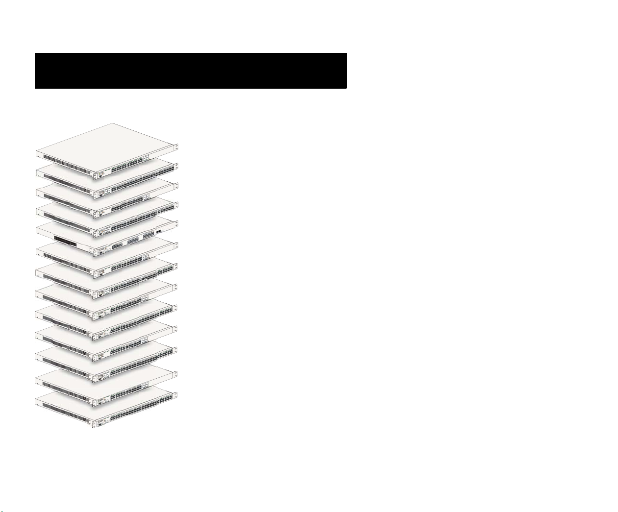
OmniSwitch 6850 Series
Features
OmniSwitch 6850-24L
OmniSwitch 6850-48L
OmniSwitch 6850-P24L
OmniSwitch 6850-P48L
OmniSwitch 6850-U24X
OmniSwitch 6850-24
OmniSwitch 6850-48
OmniSwitch 6850-24X
OmniSwitch 6850-48X
OmniSwitch 6850-P24
OmniSwitch 6850-P48
OmniSwitch 6850-P24X
OmniSwitch 6850-P48X
The OmniSwitch 6850 Series is an advanced fixed configuration family of Ethernet switches. These switches provide wire
rate Layer 2 forwarding and Layer 3 routing with advanced
services. All except OS6850-48X, OS6850-P48X, and
OS6850-U24X offer four combo ports consisting of four
shared 10/100/1000 ports and four 1000 Mbps fiber SFP ports.
• The OmniSwitch 6850-24L (OS6850-24L) is a
stackable edge/workgroup switch offering 20 unshared
10/100Base-T ports, as well as four combo ports individually configurable to be 10/100/1000Base-T or
1000Base-X high speed connections.
• The OmniSwitch 6850-48L (OS6850-48L) is a
stackable edge/workgroup switch offering 44 unshared
10/100Base-T ports, as well as four combo ports individually configurable to 10/100/1000Base-T or
1000Base-X high speed connections.
• The OmniSwitch 6850-P24L (OS6850-P24L) is a
stackable edge/workgroup switch offering 20 unshared
10/100Base-T PoE ports, as well as four combo ports
individually configurable to be 10/100/1000Base-T or
1000Base-X high speed connections.
• The OmniSwitch 6850-P48L (OS6850-P48L) is a
stackable edge/workgroup switch offering 44 unshared
October 2006 OmniSwitch 6850 Series 1

10/100Base-T PoE ports, as well as four combo ports
individually configurable to 10/100/1000Base-T or
1000Base-X high speed connections.
• The OmniSwitch 6850-U24X (OS6850-U24X) is a
stackable edge/workgroup switch offering 24
1000Base-X MiniGBIC SFP ports, two (2) 10 Gigabit
XFP slots, as well as two combo ports individually
configurable to 10/100/1000Base-T ports.
• The OmniSwitch 6850-24 (OS6850-24) is a 24-port,
10/100/1000 fixed stackable chassis with four combo
fiber SFP ports.
• The OmniSwitch 6850-P24X (OS6850-P24X) is a 24-
port, 10/100/1000 PoE fixed stackable chassis with
four combo fiber SFP ports. This switch also includes
two 10-Gigabit XFP ports.
• The OmniSwitch 6850-P48X (OS6850-P48X) is a 48-
port, 10/100/1000 PoE fixed stackable chassis. This
switch also includes two 10-Gigabit XFP ports.
The OmniSwitch 6850 Series switches are based on the same
software architecture as OmniSwitch 9000 Series switches
(e.g., OS9700). They are designed to meet the most stringent
requirements for mission-critical networks.
• The OmniSwitch 6850-48 (OS6850-48) is a 48-port,
10/100/1000 fixed stackable chassis with four combo
fiber SFP ports.
• The OmniSwitch 6850-24X (OS6850-24X) is a 24-
port, 10/100/1000 fixed stackable chassis with four
combo fiber SFP ports. This switch also includes two
10-Gigabit XFP ports.
• The OmniSwitch 6850-48X (OS6850-48X) is a 48-
port, 10/100/1000 fixed stackable chassis. This switch
also includes two 10-Gigabit XFP ports.
• The OmniSwitch 6850-P24 (OS6850-P24) is a 24-port,
10/100/1000 PoE fixed stackable chassis with four
combo fiber SFP ports.
• The OmniSwitch 6850-P48 (OS6850-P48) is a 48-port,
10/100/1000 PoE fixed stackable chassis with four
combo fiber SFP ports.
2 OmniSwitch 6850 Series October 2006
Note. The 20 and 44 unshared 10/100Base-T PoE or nonPoE ports of the 24/48 Lite versions are software upgradeable to 10/100/1000BaseT ports. Please contact your
Alcatel representative for more information.
Stand-Alone and Stacked Configurations
Stand-Alone
A stand-alone OmniSwitch 6850 Series switch is ideal for
small and medium-sized network edge applications, offering
24 ports (OS6850-24, OS6850-24X, OS6850-P24,
OS6850-P24X, OS6850-24L, OS6850-P24L, OS6850-U24X)
and 48 ports (OS6850-48, OS6850-48X, OS6850-P48,
OS6850-P48X, OS6850-48L, OS6850-P48L) switches.

These switches provide support for enterprise-based devices,
such as computer workstations or IP telephones.
A single OmniSwitch 6850 Series switch also supports 10Gigabit Ethernet uplinks for high-bandwidth connections to a
backbone or server.
the stack. This provides a virtual chassis with a 10/100/1000
capacity of up to 384 ports.
Note. Switches should be added one at a time in a stack.
Stacked Configurations
In addition to working as individual, stand-alone switches,
OmniSwitch 6850 Series switches can also be linked together
to form a single, high-density virtual chassis known as a stack.
Note. You cannot mix OS6800 and OS6850 switches in a
stack.
Stacking switches provides scalability by allowing users to
quickly and easily expand 10/100/1000 port density. Twentyfour 10/100/1000 ports are added for each OS6850-24,
OS6850-24X, OS6850-P24, OS6850-P24X, and
OS6850-U24X switch brought into the stack; forty-eight
10/100/1000 ports are added for each OS6850-48,
OS6850-48X, OS6850-P48, OS6850-P48X, and switch.
Twenty-four 10/100 ports are added for each OS6850-24L and
OS6850-P24L switch brought into the stack; forty-eight
10/100 ports are added for each OS6850-48L and
OS6850-P48L switch.
Up to eight switches can be stacked. OmniSwitch 6850 Series
switches can be mixed and matched in any combination within
As with the stand-alone configuration, a stacked virtual chassis configuration provides Gigabit Ethernet uplinks and 10Gigabit Ethernet uplinks to a backbone or server.
Network Applications
The OmniSwitch 6850 Series offers effective availability,
resiliency, and security features and are ideal for the following network applications:
• Enterprise workgroups/LAN wiring closets
• Edge deployments and branch offices
• L3 aggregation/distribution layer switches in three-tier
networks
• Small enterprise core switching
• Quality of Service (QoS) for mission critical applica-
tions
• Data center server clusters
October 2006 OmniSwitch 6850 Series 3
Availability Features
Chassis Types
The switch provides a broad variety of availability features.
Availability features are hardware- and software-based safeguards that help to prevent the loss of data flow in the unlikely
event of a subsystem failure. In addition, some availability
features allow users to maintain or replace hardware components without powering off the switch or interrupting switch
operations. Combined, these features provide added resiliency
and help to ensure that the switch or virtual chassis is consistently available for day-to-day network operations.
Some key availability features include:
• Management Module Redundancy
• Software Rollback
• Backup Power Supplies
• Hot Swapping
• Hardware Monitoring
For information on these availability features, refer to the
OmniSwitch 6850 Series Hardware Users Guide.
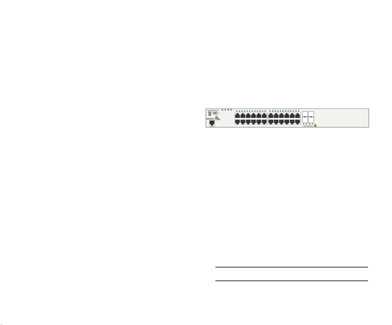
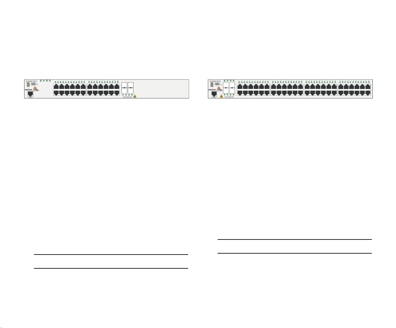
OmniSwitch 6850-24L (OS6850-24L)
The OmniSwitch 6850-24L is a stackable edge/workgroup
switch offering 20 unshared 10/100Base-T ports, as well as
four combo ports individually configurable to be
10/100/1000Base-T or 1000Base-X high speed connections.
The front panel of the OS6850-24L chassis contains the
following major components:
• System status and slot indicator LEDs
• (20) Unshared 10/100Base-T ports
• (4) Shared combo 10/100/1000Base-T ports
• (4) Combo SFP slots for 1000Base-X connections
• Console port (RJ-45)
• USB port (USB 2.0)
For more information on the OS6850-24L chassis details, refer
to “Hardware Basics” on page 57.
Note. USB 2.0 is not supported in this release.
4 OmniSwitch 6850 Series October 2006
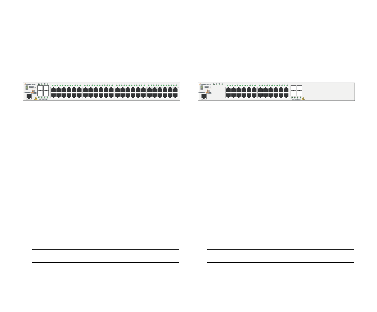
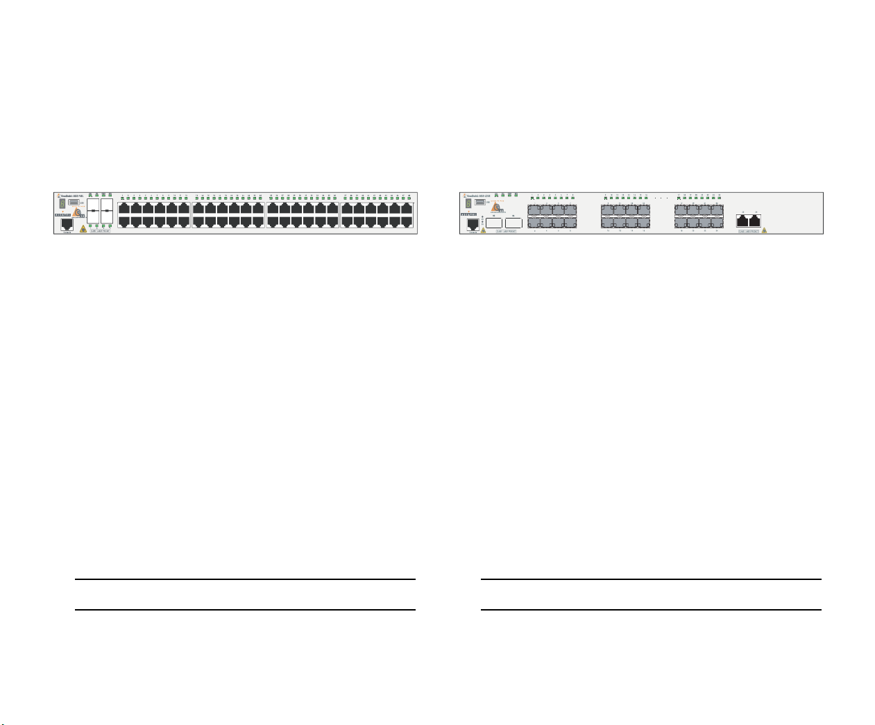
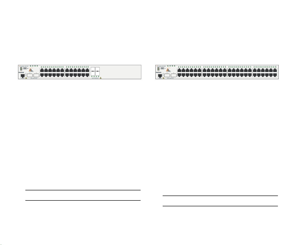
OmniSwitch 6850-48L (OS6850-48L)
OmniSwitch 6850-P24L (OS6850-P24L)
The OmniSwitch 6850-48L is a stackable edge/workgroup
switch offering 44 unshared 10/100Base-T ports, as well as
four combo ports individually configurable to
10/100/1000Base-T or 1000Base-X high speed connections.
The front panel of the OS6850-48L chassis contains the
following major components:
• System status and slot indicator LEDs
• (44) Unshared 10/100Base-T ports
• (4) Shared combo 10/100/1000Base-T ports
• (4) Combo SFP slots for 1000Base-X connections
• Console port (RJ-45)
• USB port (USB 2.0)
The OmniSwitch 6850-P24L is a stackable edge/workgroup
switch offering 20 unshared 10/100Base-T PoE ports, as well
as four combo ports individually configurable to be
10/100/1000Base-T or 1000Base-X high speed connections.
The front panel of the OS6850-P24L chassis contains the
following major components:
• System status and slot indicator LEDs
• (20) Unshared 10/100Base-T PoE ports
• (4) Shared combo 10/100/1000Base-T PoE ports
• (4) Combo SFP slots for 1000Base-X connections
• Console port (RJ-45)
• USB port (USB 2.0)
For more information on the OS6850-48L chassis details, refer
to “Hardware Basics” on page 57.
Note. USB 2.0 is not supported in this release.
October 2006 OmniSwitch 6850 Series 5
For more information on the OS6850-P24L chassis details,
refer to “Hardware Basics” on page 57.
Note. USB 2.0 is not supported in this release.
OmniSwitch 6850-P48L (OS6850-P48L)
OmniSwitch 6850-U24X (OS6850-U24X)
The OmniSwitch 6850-P48L is a stackable edge/workgroup
switch offering 44 unshared 10/100Base-T PoE ports, as well
as four combo ports individually configurable to
10/100/1000Base-T or 1000Base-X high speed connections.
The front panel of the OS6850-P48L chassis contains the
following major components:
• System status and slot indicator LEDs
• (44) Unshared 10/100Base-T PoE ports
• (4) Shared combo 10/100/1000Base-T PoE ports
• (4) Combo SFP slots for 1000Base-X connections
• Console port (RJ-45)
• USB port (USB 2.0)
The OmniSwitch 6850-U24X is a stackable edge/workgroup
switch offering 24 1000Base-X MiniGBIC SFP ports, two (2)
10 Gigabit XFP slots, as well as two combo ports individually
configurable to 10/100/1000Base-T ports.
The front panel of the OS6850-U24X chassis contains the
following major components:
• System status and slot indicator LEDs
• (22) Unshared 1000Base-X MiniGBIC SFP ports
• (2) Shared combo 1000Base-X MiniGBIC SFP ports
• (2) Combo RJ-45 10/100/1000Base-T ports
• (2) 10 Gigabit XFP slots
• Console port (RJ-45)
• USB port (USB 2.0)
For more information on the OS6850-P48L chassis details,
refer to “Hardware Basics” on page 57.
Note. USB 2.0 is not supported in this release.
6 OmniSwitch 6850 Series October 2006
For more information on the OS6850-U24X chassis details,
refer to “Hardware Basics” on page 57.
Note. USB 2.0 is not supported in this release.
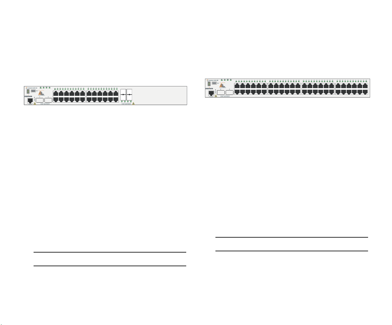
OmniSwitch 6850-24 (OS6850-24)
OmniSwitch 6850-48 (OS6850-48)
The OmniSwitch 6850-24 is a stackable edge/workgroup
switch offering 24 10/100/1000Base-T ports, as well as four
SFP ports for high-speed connections.
The front panel of the OS6850-24 chassis contains the following major components:
• System status and slot indicator LEDs
• (20) Unshared 10/100/1000Base-T ports
• (4) Shared combo 10/100/1000Base-T ports
• (4) Combo SFP slots for 1000Base-X connections
• Console port (RJ-45)
• USB port (USB 2.0)
For more information on the OS6850-24 chassis details, refer
to “Hardware Basics” on page 57.
The OmniSwitch 6850-48 is a stackable edge/workgroup
switch offering 48 10/100/1000Base-T ports, as well as four
SFP ports for high-speed connections.
The front panel of the OS6850-48 chassis contains the following major components:
• System status and slot indicator LEDs
• (44) Non-combo 10/100/1000Base-T ports
• (4) Combo 10/100/1000Base-T ports
• (4) Combo SFP slots for 1000Base-X connections
• Console port (RJ-45)
For more information on the OS6850-48 chassis details, refer
to “Hardware Basics” on page 57.
Note. USB 2.0 is not supported in this release.
Note. USB 2.0 is not supported in this release.
October 2006 OmniSwitch 6850 Series 7
OmniSwitch 6850-24X (OS6850-24X)
OmniSwitch 6850-48X (OS6850-48X)
The OmniSwitch 6850-P24X is a stackable edge/workgroup
switch offering 24 10/100/1000Base-T ports, as well as four
SFP ports for high-speed connections. This switch also
includes two 10-Gigabit XFP ports.
The front panel of the OS6850-24X chassis contains the
following major components:
• System status and slot indicator LEDs
• (20) Unshared 10/100/1000Base-T ports
• (4) Shared combo 10/100/1000Base-T ports
• (4) Combo SFP slots for 1000Base-X connections
• (2) 10-Gigabit XFP slots
• Console port (RJ-45)
• USB port (USB 2.0)
For more information on the OS6850-24X chassis details,
refer to “Hardware Basics” on page 57.
The OmniSwitch 6850-48X is a stackable edge/workgroup
switch offering 48 10/100/1000Base-T ports.This switch also
includes two 10-Gigabit XFP ports.
The front panel of the OS6850-48X chassis contains the
following major components:
• System status and slot indicator LEDs
• (48) Unshared 10/100/1000Base-T ports
• (2) 10-Gigabit XFP slots
• Console port (RJ-45)
• USB port (USB 2.0)
For more information on the OS6850-48X chassis details,
refer to “Hardware Basics” on page 57.
Note. USB 2.0 is not supported in this release.
Note. USB 2.0 is not supported in this release.
8 OmniSwitch 6850 Series October 2006
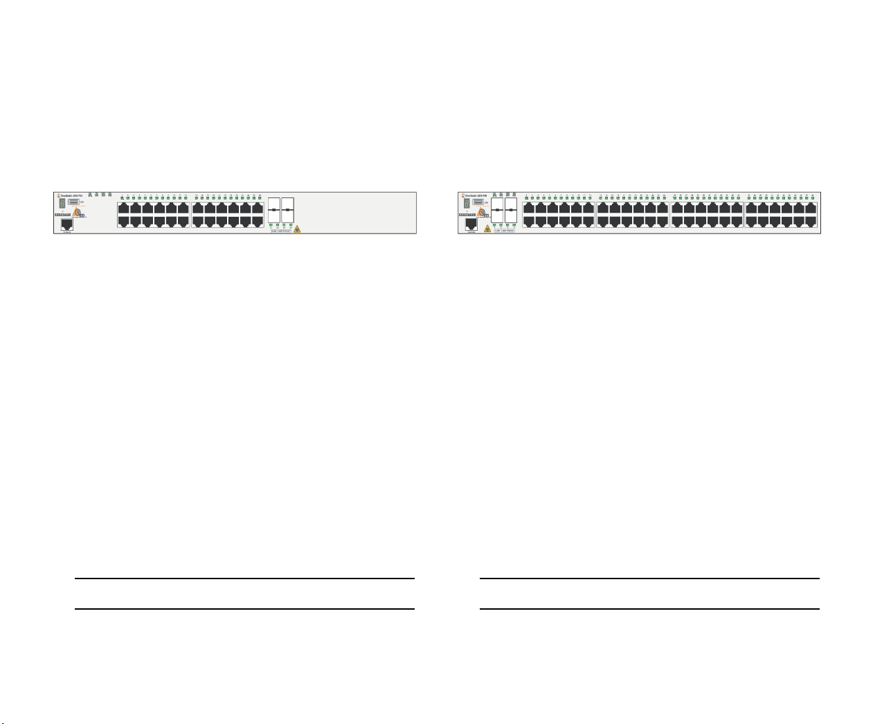
OmniSwitch 6850-P24 (OS6850-P24)
OmniSwitch 6850-P48 (OS6850-P48)
The OmniSwitch 6850-P24 is a stackable edge/workgroup
switch offering 24 Power over Ethernet (PoE)
10/100/1000Base-T ports, as well as four SFP ports for highspeed connections.
The front panel of the OS6850-P24 chassis contains the
following major components:
• System status and slot indicator LEDs
• (20) Unshared 10/100/1000Base-T PoE ports
• (4) Shared combo 10/100/1000Base-T PoE ports
• (4) Combo SFP slots for 1000Base-X connections
• Console port (RJ-45)
• USB port (USB 2.0)
The OmniSwitch 6850-P48 is a stackable edge/workgroup
switch offering 48 Power over Ethernet (PoE)
10/100/1000Base-T ports, as well as four SFP ports for highspeed connections.
The front panel of the OS6850-P48 chassis contains the
following major components:
• System status and slot indicator LEDs
• (44) Unshared 10/100/1000Base-T PoE ports
• (4) Shared combo 10/100/1000Base-T PoE ports
• (4) Combo SFP slots for 1000Base-X connections
• Console port (RJ-45)
• USB port (USB 2.0)
For more information on the OS6850-P24 chassis details, refer
to “Hardware Basics” on page 57.
Note. USB 2.0 is not supported in this release.
October 2006 OmniSwitch 6850 Series 9
For more information on the OS6850-P48 chassis details, refer
to “Hardware Basics” on page 57.
Note. USB is not supported in this release.
OmniSwitch 6850-P24X (OS6850-P24X)
OmniSwitch 6850-P48X (OS6850-P48X)
The OmniSwitch 6850-P24X is a stackable edge/workgroup
switch offering 24 Power over Ethernet (PoE)
10/100/1000Base-T ports, as well as four SFP and two XFP
ports for high-speed connections.
The front panel of the OS6850-P24X chassis contains the
following major components:
• System status and slot indicator LEDs
• (20) Unshared 10/100/1000Base-T PoE ports
• (4) Shared combo 10/100/1000Base-T PoE ports
• (4) Combo SFP slots for 1000Base-X connections
• (2) 10-Gigabit XFP slots
• Console port (RJ-45)
• USB port (USB 2.0)
For more information on the OS6850-P24X chassis details,
refer to “Hardware Basics” on page 57.
The OmniSwitch 6850-P48X is a stackable edge/workgroup
switch offering 48 Power over Ethernet (PoE)
10/100/1000Base-T ports, as well as four SFP and two XFP
ports for high-speed connections.
The front panel of the OS6850-P48X chassis contains the
following major components:
• System status and slot indicator LEDs
• (48) Unshared 10/100/1000Base-T PoE ports
• (4) Combo SFP slots for 1000Base-X connections
• (2) 10-Gigabit XFP slots
• Console port (RJ-45)
• USB port (USB 2.0)
For more information on the OS6850-P48X chassis details,
refer to “Hardware Basics” on page 57.
Note. USB 2.0 is not supported in this release.
Note. USB 2.0 is not supported in this release.
10 OmniSwitch 6850 Series October 2006

Note. The 20 and 44 unshared 10/100Base-T PoE or nonPoE ports of the 24/48 Lite versions are software upgradeable to 10/100/1000BaseT ports. Please contact your
Alcatel representative for more information.
Power Supplies
OmniSwitch 6850 Series switches support power supply
components. The components include:
• PS-120W-DC backup power supply module
• PS-126W-AC backup power supply module
• PS-360W-AC backup power supply module
• PS-510W-AC backup power supply module
• Backup power supply connector cable
When backup power supply components are installed, the
primary (factory-installed) power supply continues to take on
the full power load for switch operations. Meanwhile, the
backup power supply operates in active standby mode. If the
primary power supply fails unexpectedly, the backup power
supply automatically takes up the full power load without
disrupting the switch.
.
The OmniSwitch 6850 Series backup power supply system is
chassis-based with each chassis supporting up to eight backup
power supplies. This provides 1:1 redundancy for stacks of up
to eight switches
October 2006 OmniSwitch 6850 Series 11

Setting Up the Hardware
Items Required
In addition to the materials and components provided in the
OmniSwitch 6850 Series shipment, you must provide the
following items in order to complete this installation:
• Grounding wrist strap
• Phillips screwdriver
• Serial cable
• Rack mount screws, if applicable
Site Preparation
Environmental Requirements
OmniSwitch 6850 Series switches have the following environmental and airflow requirements:
• The installation site must maintain a temperature
between 0° and 45° Celsius (32° and 113° Fahrenheit)
and not exceed 95 percent maximum humidity (noncondensing) at any time.
• Be sure to allow adequate room for proper air ventila-
tion and access at the front, back, and sides of the
switch. No clearance is necessary at the top or bottom
of the chassis. Refer to page 16 for minimum clearance requirements.
Electrical Requirements
OmniSwitch 6850 Series switches have the following general
electrical requirements:
• Each switch requires one grounded AC power source.
• Grounded AC power source must be 110V for North
American installations (220V international).
• Each supplied AC power cord is approximately 2
meters (6.5 feet) long. Do not use extension cords.
Weight Considerations
OS6850-24L
A single OS6850-24L weighs approximately 14 lbs (6.24
Kgs). A stack of eight OS6850-24L switches weighs approximately 112 lbs (50 Kgs).
OS6850-48L
A single OS6850-48L weighs approximately 14 lbs (6.24
Kgs). A stack of eight OS6850-48L switches weighs approximately 112 lbs (50 Kgs).
12 Setting Up the Hardware October 2006

OS6850-P24L
OS6850-24X
A single OS6850-P24L weighs approximately 14 lbs (6.24
Kgs). A stack of eight OS6850-P24L switches weighs approximately 112 lbs (50 Kgs).
OS6850-P48L
A single OS6850-P48L weighs approximately 14 lbs (6.24
Kgs). A stack of eight OS6850-P48L switches weighs approximately 112 lbs (50 Kgs).
OS6850-U24X
A single OS6850-U24X weighs approximately 14 lbs (6.24
Kgs). A stack of eight OS6850-U24X switches weighs approximately 112 lbs (50 Kgs).
OS6850-24
A single OS6850-24 weighs approximately 14 lbs (6.24 Kgs).
A stack of eight OS6850-24 switches weighs approximately
112 lbs (50 Kgs).
OS6850-48
A single OS6850-48 weighs approximately 14 lbs
(6.24 Kgs). A stack of eight OS6850-48 switches weighs
approximately 112 lbs (50 Kgs).
A single OS6850-24X weighs approximately 14 lbs (6.24
Kgs). A stack of eight OS6850-24X switches weighs approximately 112 lbs (50 Kgs).
OS6850-48X
A single OS6850-48X weighs approximately 14 lbs (6.24
Kgs). A stack of eight OS6850-48X switches weighs approximately 112 lbs (50 Kgs).
OS6850-P24
A single OS6850-P24 weighs approximately 14 lbs (6.24
Kgs). A stack of eight OS6850-P24 switches weighs approximately 112 lbs (50 Kgs).
OS6850-P48
A single OS6850-P48 weighs approximately 14 lbs
(6.24 Kgs). A stack of eight OS6850-P48 switches weighs
approximately 112 lbs (50 Kgs).
OS6850-P24X
A single OS6850-P24X weighs approximately 14 lbs (6.24
Kgs). A stack of eight OS6850-P24X switches weighs approximately 112 lbs (50 Kgs).
October 2006 Setting Up the Hardware 13

OS6850-P48X
A single OS6850-P48X weighs approximately 14 lbs
(6.24 Kgs). A stack of eight OS6850-P48X switches weighs
approximately 112 lbs (50 Kgs).
Items Included
Your OmniSwitch 6850 Series switch order includes the
following items:
• OmniSwitch 6850 Series chassis
• Rack mount flanges with attachment screws (rack
mount flanges may be pre-installed on some orders)
• Power cord (country-specific)
• OmniSwitch 6850 Series-specific user documentation:
OmniSwitch 6850 Series Getting Started Guide
OmniSwitch 6850 Series Hardware Users Guide
OmniSwitch CLI Reference Guide
Depending on the items ordered for your specific network
requirements, the following optional items may also be
included:
• Stacking cables (per order)
• Combo port SFPs (per order)
• 10-Gigabit XFPs (per order)
• Backup power supply components and cables
(per order)
OmniSwitch 6800/6850/9000 Switch Management
Guide
OmniSwitch 6800/6850/9000 Network Configuration
Guide
OmniSwitch 6800/6850/9000 Advanced Routing
Configuration Guide
14 Setting Up the Hardware October 2006

Unpacking and Initial Setup
Unpacking the Chassis
To protect your OmniSwitch chassis and hardware components from electrostatic discharge (ESD) and physical damage,
read all unpacking recommendations and instructions carefully before beginning.
Recommendations
• Unpack your OmniSwitch chassis as close as possible
to the location where it will be installed.
4 Carefully remove any foam pads and protective plastic
from the switch chassis.
Note. Alcatel provides factory-installed blank cover plates
for empty backup power supply or 10-Gigabit expansion
module bays. Do not remove these cover plates unless a
backup power supply or expansion module is to be
installed immediately at the corresponding bay.
5 If you are installing multiple switches in a stacked
configuration, repeat steps 1 through 4 for the remaining
switches that will make up the stack.
• Depending on your order, Small Form-Factor Plugga-
bles (SFPs), stacking cables and backup power supply
components may be packaged separately. In order to
6 Once all OmniSwitch 6850 Series switches have been
removed from their packaging, continue to “Setting Up
the Switch.”
greatly reduce exposure to electrostatic discharge
(ESD) and physical damage, do not unpack these items
until they are ready to be installed.
Instructions
1 Carefully cut the tape along the seam at the top of the
box containing the chassis.
2 Lift the box’s top flaps. Remove any smaller boxes or
pouches that are enclosed and set them aside.
3 Lift the chassis out of the packaging.
October 2006 Setting Up the Hardware 15
Setting Up the Switch
Never obstruct the air vents located at the left and right sides
of the chassis.
Note. Due to their airflow and access requirements,
OmniSwitch 6850 Series switches cannot be wallmounted.
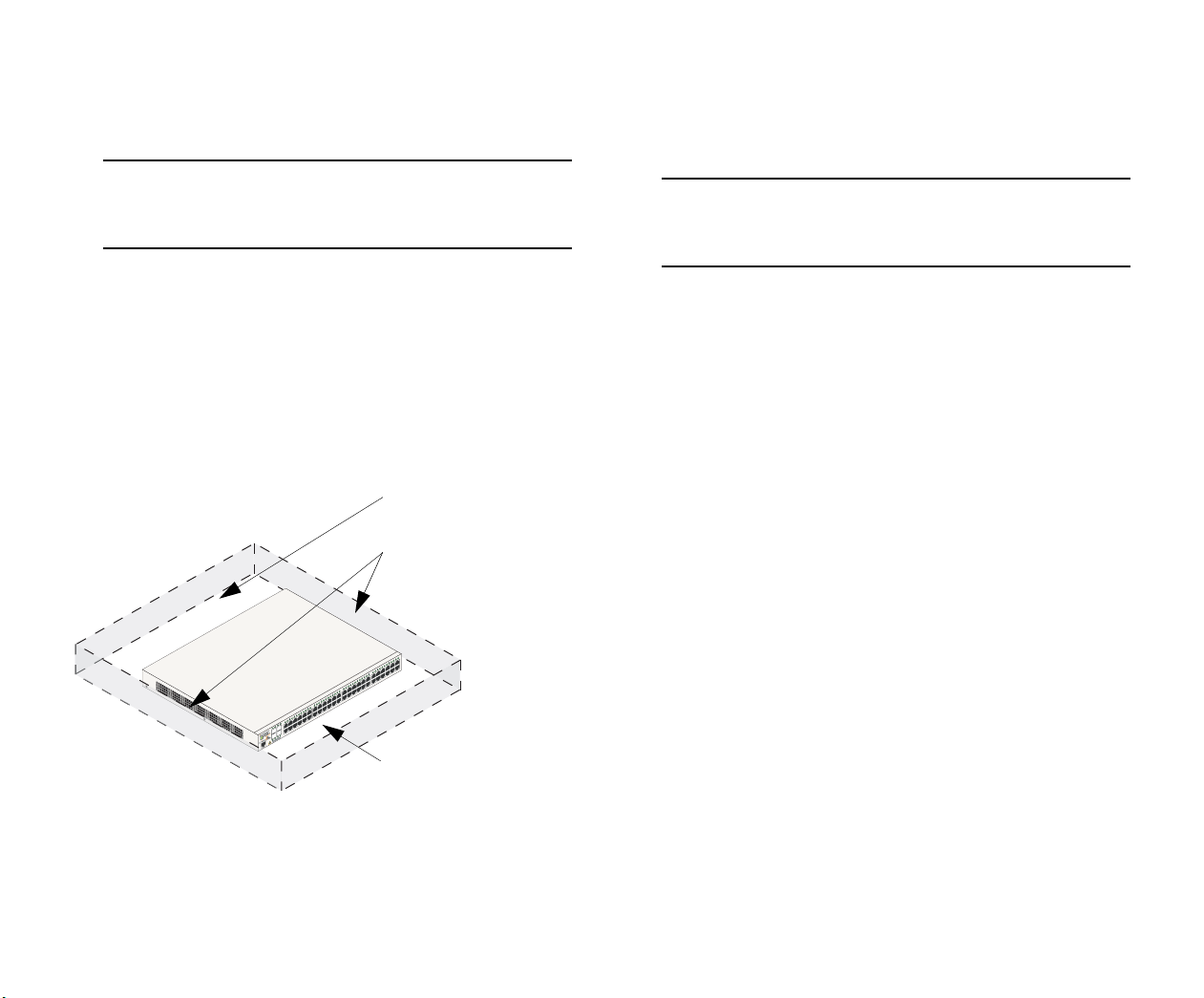
Airflow Considerations
Be sure that your switch is placed in a well-ventilated, staticfree environment. Always allow adequate clearance at the
front, rear, and sides of the switch.
The following diagram shows recommended minimum clearances for adequate chassis airflow and access to components at
the rear of the chassis.
Rear. 5 inches minimum
at rear of chassis.
Sides. 2 inches minimum
at left and right sides for
chassis airflow.
Note. Clearance is not required at the top and bottom of
the chassis. For detailed chassis airflow diagrams, refer to
the OmniSwitch 6850 Series Hardware Users Guide.
Installation Options
There are two ways in which the OmniSwitch 6850 Series
switches can be installed:
• Tabletop installation
• Rack-mount installation
For information on setting up a switch as a tabletop unit, refer
to “Installing the Switch on a Tabletop or Bench.” For information on rack-mounting the switch, refer to
“Rack-Mounting the Switch” on page 18.
Front. 6 inches minimum
at front of chassis for
cable access and LED
visibility.
Chassis Top View
16 Setting Up the Hardware October 2006

Installing the Switch on a Tabletop or Bench
OmniSwitch 6850 Series switches can be installed freestanding as tabletop units. Place your switch on a stable, flat, and
static-free surface.
Note. OmniSwitch 6850 Series switches must be placed
“right side up.” Never attempt to operate a switch positioned on its side.
Tabletop Mounting Steps
To install the switch as a tabletop unit, follow the steps below:
1 Position the chassis on the table or bench where it is to
be installed.
2 Be sure that adequate clearance has been provided for
chassis airflow and access to the front, back, and sides of
the switch. For recommended clearances, refer to page 16.
Also, be sure that you have placed the chassis within reach
of all required AC power sources.
Note. If you are installing a single (i.e., stand-alone)
switch, continue to “Connections and Cabling” on page 24
for additional setup procedures.
If you are placing multiple switches in a stacked configuration, carefully stack the remaining switches, one on top
of the other. Up to eight switches may be stacked to form
a single virtual chassis. Be sure to maintain adequate
clearance at the front, rear, left, and right side of all
switches (see page 16). Also, be sure that you have placed
all switches in the stack within reach of required AC
power sources.
October 2006 Setting Up the Hardware 17
Rack-Mounting the Switch
Refer to the important guidelines below before installing the
OmniSwitch chassis in a rack.
• Review page 16 for important chassis airflow and
access recommendations before installing.
Rack Mounting Steps
• It is recommended that two people install the switch in
the rack—one person to hold the chassis and position it
in the rack, and a second person to secure the chassis to
the rack using attachment screws (not supplied).
• Alcatel provides two rack-mount flanges with each
OmniSwitch 6850 Series switch. These flanges support
standard 19-inch rack mount installations. These
flanges must be attached to the chassis before the
switch can be rack mounted.
Note. If you are installing the switch in a 23-inch wide
rack, Alcatel offers optional 23-inch rack-mounting hardware. For more information, contact your Alcatel representative.
• Alcatel does not provide rack-mount screws. Use the
screws supplied by the rack vendor.
• To prevent a rack from becoming top heavy, it is
recommended that you install heavier equipment at the
bottom of the rack whenever possible.
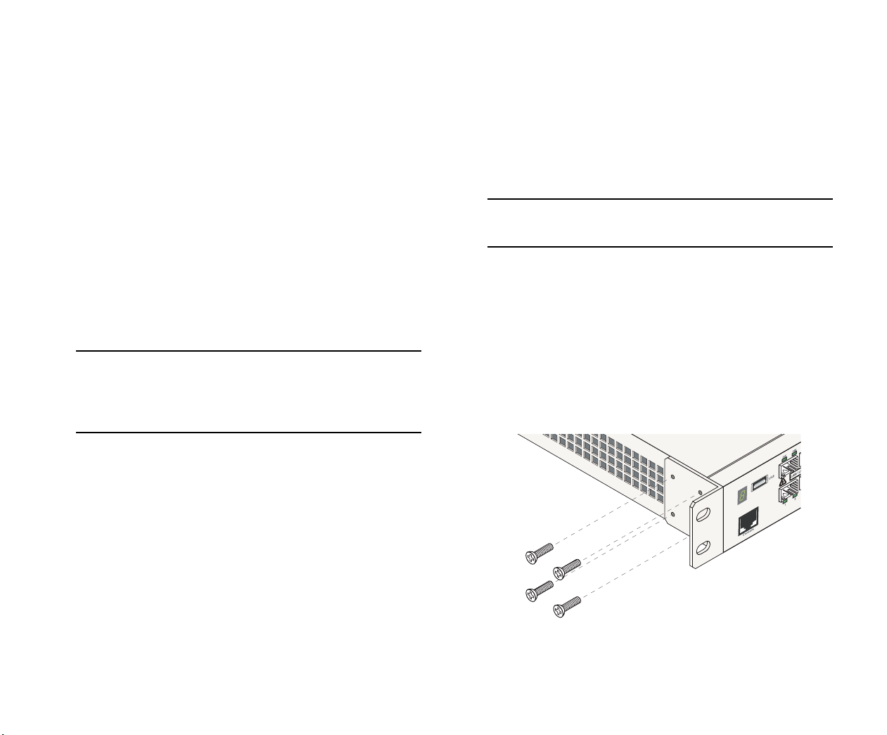
To rack-mount the switch, follow the steps below.
Note. Rack-mount flanges may come factory-installed in
some cases. If this is the case, skip steps 1 and 2 below.
1 Align the holes in the provided rack-mount flanges
with the four threaded holes in the OmniSwitch chassis.
These threaded holes are located in the left and right sides
of the chassis, near the front panel.
2 Attach the flanges to the chassis using the provided
Phillips-head screws. Be sure to tighten each of the screws
firmly using a Phillips screwdriver.
45
46
Console
• If you are installing the switch in a relay rack, be sure
to install and secure the rack as per the rack manufacturer’s specifications.
Attaching a Rack-Mount Flange
18 Setting Up the Hardware October 2006
 Loading...