

Page 1

Part No. 060155-10, Rev. A
July 2002
OmniStack® 6148
Getting Started Guide
Page 2

An Alcatel service agreement brings your company the assurance of 7x24 no-excuses
technical support. You’ll also receive regular software updates to maintain and
maximize your Alcatel product’s features and functionality and on-site hardware
replacement through our global network of highly qualified service delivery partners.
Additionally, with 24-hour-a-day access to Alcatel’s Service and Support web page,
you’ll be able to view and update any case (open or closed) that you have reported to
Alcatel’s technical support, open a new case or access helpful release notes, technical
bulletins, and manuals. For more information on Alcatel’s Service Programs, see our
web page at www.ind.alcatel.com, call us at 1-800-995-2696, or email us at
support@ind.alcatel.com.
This Manual documents OmniStack 6148 hardware and software.
The functionality described in this Manual is subject to change without notice.
©
Copyright
reproduced in whole or in part without the express written permission of Alcatel Internetworking,
Inc.
Alcatel
France. OmniSwitch
Omni Switch/Router™, SwitchExpert
Inc. All other brand and product names are trademarks of their respective companies.
2002 by Alcatel Internetworking, Inc. All rights reserved. This document may not be
®
and the Alcatel logo are registered trademarks of Compagnie Financiére Alcatel, Paris,
®
and OmniStack® are registered trademarks of Alcatel Internetworking, Inc.
SM
, the Xylan logo are trademarks of Alcatel Internetworking,
26801 West Agoura Road
Calabasas, CA 91301
(818) 880-3500 FAX (818) 880-3505
info@ind.alcatel.com
US Customer Support-(800) 995-2696
International Customer Support-(818) 878-4507
Internet-http://www.ind.alcatel.com
Page 3

This equipment has been tested and found to comply with the limits for Class A digital
Warning
device pursuant to Part 15 of the FCC Rules. These limits are designed to provide
reasonable protection against harmful interference when the equipment is operated in a
commercial environment. This equipment generates, uses, and can radiate radio
frequency energy and, if not installed and used in accordance with the instructions in
this guide, may cause interference to radio communications. Operation of this equipment
in a residential area is likely to cause interference, in which case the user will be required
to correct the interference at his own expense.
The user is cautioned that changes and modifications made to the equipment without
approval of the manufacturer could void the user’s authority to operate this equipment.
It is suggested that the user use only shielded and grounded cables to ensure compliance
with FCC Rules.
This digital apparatus does not exceed the Class A limits for radio noise emissions from
digital apparatus set out in the radio interference regulations of the Canadian
department of communications.
Le present appareil numerique níemet pas de bruits radioelectriques depassant les
limites applicables aux appareils numeriques de la Class A prescrites dans le reglement
sur le brouillage radioelectrique edicte par le ministere des communications du Canada.
Page 4

Page 5

Contents
Introduction 1
Installing the Switch 2
Package Contents 2
Description of Hardware 2
Mounting the Switch 3
Stacking Switches on a Flat Surface 3
Mounting Switches in a Rack 4
Installing a Management Module 4
Installing Optional Media and Stacking Modules 5
Connecting Stacking Modules across Multiple Switches 5
Installing a GBIC Transceiver 6
Connecting the Switch System 7
Making a Connection to an RJ-45 Port 7
Connecting to a 100BASE-FX Port 8
Connecting to a Gigabit Fiber Optic Port 8
Connecting to a 1000BASE-T Port 9
Powering On the Switch 9
Verifying Port Status 10
Verifying System Operation 10
Applications 11
Product Specifications 13
Base Unit 13
Physical Characteristic s 13
Switching Criteria 13
Traffic Control 13
Modules 14
Management Module (OS-6148-MNGT-KIT) 14
100BASE-FX Module (OS-6ESM-100FM-2) 14
1000BASE-T Module (OS-6GSM-T-1) 14
1000BASE-SX Module (OS-6GSM-FM-1) 14
1000BASE-LX Module (OS-6GSM-FS-1) 14
GBIC Module (OS-6GSM-GBIC-1) 15
Stacking Module (OS-6STK-KIT) 15
Redundant Stacking Module (OS-6100-RST-KIT) 15
Troubleshooting 15
Diagnosing Switch Indicato rs 15
Power and Cooling Problems 16
Installation 16
Port and Cable Assignments 17
i
Page 6

Contents
RJ-45 Port Description 17
10BASE-T/100BASE-TX Pin Assignments 17
1000BASE-T Pin Assignments 18
1000BASE-T Cable Requirements 18
Cable Testing for Existing Category 5 Cable 18
Adjusting Existing Categ ory 5 Cabling 18
EMI Certification 19
FCC Class A Certification (USA) 19
Canada Department of Communications - Class A 19
BSMI Class A (Taiwan) 19
VCCI Class A Compliance (Japan) 19
CE Mark Declaration of Conformance for EMI and Safety (EEC) 20
Safety Compliance 21
Warning: Fiber Optic Port Safety 21
Avertissment: Ports pour fibres optiques - sécurité sur le plan optique 21
Warnhinweis: Faseroptikanschlüsse - Optische Sicherheit 21
Underwriters Laboratories Inc. (USA) 21
Wichtige Sicherheitshinweise (Germany) 22
Optional Hardware 22
ii
Page 7

Introduction
The Alcatel OmniStack® 6148 is perfect for moving workgroups from conventional
10 Mbps Ethernet to multiple-segment 100 Mbps Fast Ethernet, and for
consolidating your network equipment into a single, clean, efficient, and super-fast
switch stack. This switch system delivers dedicated 100 Mbps links to each attached
LAN segment (independent collision domain) or to any PC attached directly to the
stack – all with conventional cabling and adapters. It completely eliminates the
bottlenecks of shared 10 M bps Ethernet networks by provid ing a w i de bandwidth of
up to 13.6 Gbps per switch, and a stack bac kplane that can operate at up to
9.6 Gbps. This makes it ideal for increasing the throughput of in terconnected
Ethernet and Fast Ethernet hubs or server farms.
This switch includes three slots on the rear panel for various modules:
• The upper slot is fo r an SNMP /RMON Manag ement Mod ule. The stack s upports one
master and one backup management agent.
• The lower right slot is for optional media expansion modules, including a dual-port
100 Mbps fiber optic modul e t ha t ca n be connected to a remote site up t o
2 kilometers (1.24 miles) away, or a single-port Gigabit module that can be used to
uplink to a collapsed Gigabi t back bone or for a high-speed server connection.
• The lower left slot is for either an optional media expansion module or Stacking
Module. (Up to three sw itch uni t s can be stacked together usi ng Stacking
Modules.)
When the Management M odule is installed, this system can pro vi de a w id e ar ra y of
advanced features:
• Master agent module m anages entire stack in-band or o ut -o f-band
• Backup agent module pro vides fault tolerance
• A fault-tolerant closed -loop stack architecture is sup por t ed w i t h a Redundant
Stacking Module
• Supports Telnet, SNMP/RMON and Web-based inter f ace
• Four-group RMON (includi n g St at istic s, His tory , Alar m s a nd Events)
• Spanning Tree Algorithm for r edundant paths between sw itc hes
• VLAN support for up to 256 gr oups, port-based or with 802.1Q VLAN tagging
• GVRP for automatic VLAN learning*
• IGMP multicast filtering
• Quality of Service support s tw o le vels of priority with Weighted Fair Q ueueing
• Configurable broadc ast st or m control
• Port mirroring (for r eal-time de bugging without affecting the tar get port)
• Port trunking (up to 5 trunks per switch or 12 trunks for the entire stack, each trunk
contains 2~4 ports)
* This feature is not supported in the current firmware release.
The Management Module allows you to configure or mo ni tor t he switch using the
embedded
switch, you can
network connection to manage the switch using Telnet, the on-board Web agent, or
any SNMP-based network management software.
management program or SNMP/RMO N applications. To manage the
make a direct connection to the console port. You can also make a
1
Page 8

OmniStack® 6148
Installing the Switch
Before installing the switch verif y t hat you have all the items listed under “P ackage
Contents.” If any of the items are m i ssing or damaged, contact your lo cal Al catel
distributor. Also be sure you have all the necessary tools and cabling befo re
installing the switch. Note th at this switch can be installed on any suitably large flat
surface or in a standard EIA 19-inch rack. After installing the switch, refer to the
Users Guide to set up its more ad vanced features, such as Spanning Tree Protocol
or VLAN port groups.
Package Contents
This package includes:
®
OmniStack
• Four rubber foot pads • This Getting Started Gui de
• Rack mount bracket kit • Release Notes
• AC power cord • Owner registratio n car d
OmniStack
• Management Modul e • Release Notes
• Console cable • Owner registratio n car d
• Users Guide
Description of Hardware
The base unit contains 48 10BASE-T/100BAS E- TX por ts, plus three slots on the
rear panel for various modules. A Management Module can be installed in the upper
slot on the rear panel (see page 3). Th e low er -left sl ot can be used for an optional
media expansion module or Stacking Module, while the l ower-rig ht slot can be used
for a media expansion module. Note that the media expansion mo dul e s in cl ud e a
Fast Ethernet fiber optic module with two 100BASE-FX (SC type) ports or a one port
Gigabit 1000BASE-SX (SC type), 1000BASE- LX (SC type), 1000BASE-T, or GBIC
uplink module.
All RJ-45 ports on the base unit ope ra te at 10 or 100 Mbps, and support
auto-negotiation of speed, duplex mode (i.e., half or full duplex), and flow control.
The 1000BASE-SX and 1000BASE-LX ports are fixed at 1000 Mbps but
auto-negotiate duplex mode. Th e 10 00BASE-T auto-negotiates duplex mo de and
auto-negotiates speed to 10 /100/1000 Mbps. The 100BASE-FX module is fixed at
the 100 Mbps, full duplex. All med ia types can auto-negotiate flow control.
Note that when using auto -n egotiation, the speed, transm ission mode and flow
control can be automatically set if this feature is also supp or te d by the attached
device. Otherwise, these items can be manually conf i gured for any connection.
The base unit also includes a display panel for key system and port indications that
simplify installation and net work troubleshooting.
6148
®
6148 Management Module Kit
2
Page 9
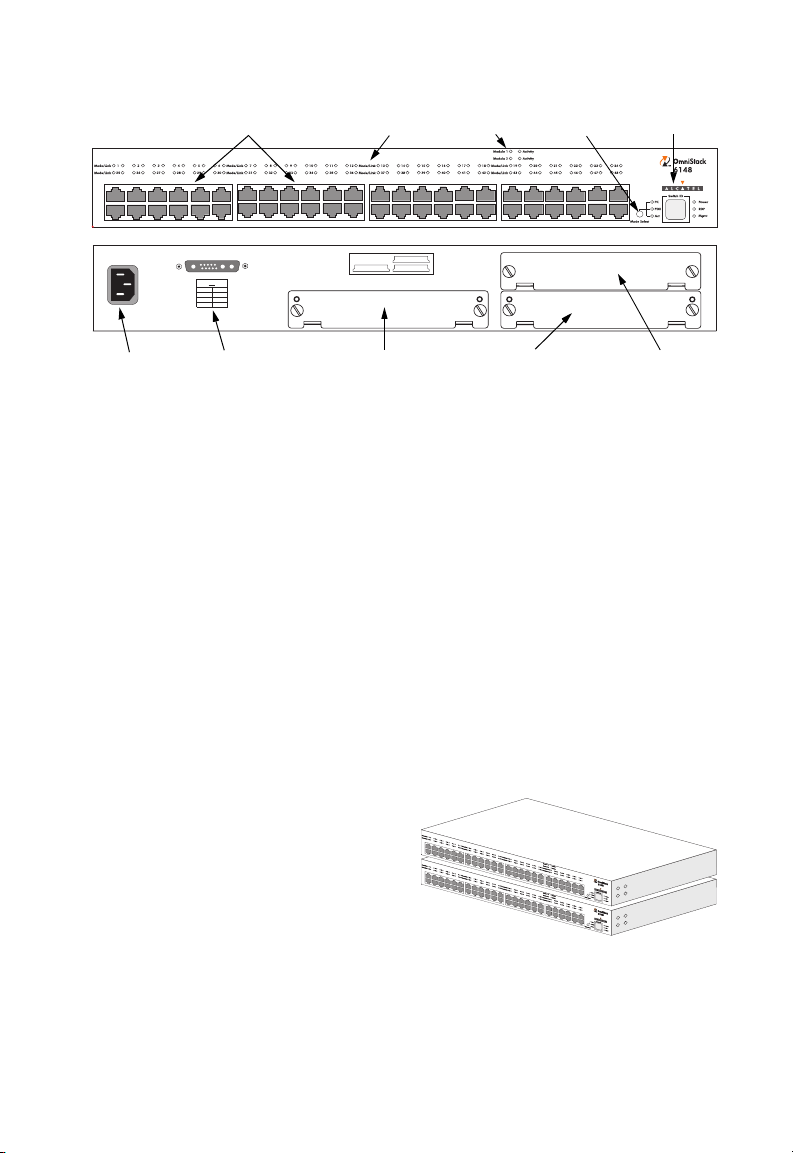
The following figure show s t he components of this switch syst em :
10/100 Mbps
RJ-45 Ports
Port Status
Indicators
Module
Indicators
Selection
Installing the Switch
Mode
System
Indicators
1
100-240V~ 50-60Hz 2A
Power
Socket
DCINPUT
VA
3.3 15
53
12 0.7
RPU
Connector
Media or Stacking
MNGT
Module2 Module1
stackingmodule can beinstalled in module 2only
Module Slot
Media
Module Slot
Management
Module Slot
Mounting the Switch
This switch can be placed directly on your desktop, or mounted in a rack.
Before you start installing the switch , make sure you can provide the right oper at i ng
environment, including power requirements, sufficient physical space, and proximity
to other network devices t hat are to be connected. Verify the following installat io n
requirements:
• Power requirements: 100 to 240 VAC (± 10%) at 50 to 60 Hz (± 3 Hz). The switch’s
power supply automat ic all y adj usts to the input voltage level.
• The switch should be located in a cool dry place, with at least 10 cm (4 in.) of space
on the sides for ventilation.
• Place the switch out of direct sunlight, and away from heat sources or areas with a
high amount of electromagnetic interference.
• If you intend to mount the switch in a rack, make sure you have all the necessary
mounting screws, brackets, bolts and nuts, and the rig ht too l s.
• Check if network cables and connectors needed for inst al l at ion are available.
Stacking Switches on a Flat Surface
The OmniStack® 6148 can be stacked
anywhere there is enough flat space, such
as on a table or desktop.
1. Stick the self-adhesive rubber foot
pads (that come with this package) on
each of th e 4 c oncav e sp ace s l ocat ed
on the bottom of the first switch.
2. Place the first switch on a firm flat sur fa ce wh er e you want to install the stack.
3. Repeat step 1 for each switch before stacking them. The switch’s rubber foot
pads cushion the switch a ga in st shock/vibrations and provide space between
each switch for vent ilation.
1
1
3
Page 10

OmniStack® 6148
Mounting Switches in a Rack
Please comply with the fol low i ng inst r uctions to ensure that your switch is securely
mounted in the rack.
1. Use a standard EIA 19-inch rack.
2. Position the switch in the rack by lining up
the holes i n th e att ac hed br ack ets wit h th e
appropriate holes on the rac k, and the n
use the rack-mount sc rew s to mo unt the
1
switch in the rack.
Installing a Management Module
One Management Module is required to manage all of the switches in the stack. One
other backup Management Module may also be installed in the stack to provide fault
tolerance. A Management Module only installs in a switch’s rear-panel upper slot, do
not try to install it in either of the two lower slots.
If you install a backup Management Module, it will automatically take over from the
master should it fail. The switch with the lowest stack unit ID will always act as the
master agent. For more informatio n on switch manag ement and the fail-over
process, see the OS-61 48 Users Guide.
Note: A Management Module may be installed in any unit in the stack, but it is
suggested that the module be installed in the switch with the stack unit ID of “1.” In
a stack with no “closed-loop” (see “Connecting Stacking Modules across Multiple
Switches” on page 5), unit ID 1 will be the switch without a connection on the
Stacking Modules “UP” port. For a closed-loop stack, unit ID 1 will be the switch
that has the Redundant Stacking Module installed.
You can install a Management M odule as described below:
1. Disconnect power to the switch (the modules are not hot - sw appable).
2. Remove the face plate on th e sw it ch’s up per slot by removing the two scr ew s
with a flat-head screwdriver.
3. Before opening the package tha t contain s th e m odule, touch the bag to the
switch casing to discharge any potential static electricity.
4. Remove the module from the anti-static shielded bag.
5. Holding the module level, gently push it all the way into the slot along the guide
rails, ensuring that it firmly en gages with the connector.
6. If you are sure the module is properly mated with the conne ctor, tighten the
retainer screws to secure th e module in the slot.
Caution: The slide-in modules are not hot-swappable. Be sure you power off the switch
before installing any of these modules.
4
Page 11

Installing the Switch
Installing Optional Media and Stacking Modules
The two lower slots on the rear panel of th e sw it ch are provided for various op tion al
media expansion modules (10 0BASE-FX or Gigabit) or Stacking Modules. The
100BASE-FX fiber optic module can be used to connect to remote sites, and a
Gigabit module can be used as a network backbone. You can install the media
expansion modules in either of the two lower slots, but the Stacking Module must
only be installed in the lower-left slot.
Y ou can install a module as described below:
1. Disconnect power to the switch (the
modules are not hot-swappable).
2. Remove the face plate on th e
appropriate slot by remov i ng t he t wo
screws with a flat-hea d sc rewdriver.
3. Before opening the package tha t
contains the module, touch t he ba g t o
the switch casing to discharge any potential static elect r ic ity.
4. Remove the module from the anti-static shielded bag.
5. Holding the module level, gently push it all the way into the slot along the guide
rails, ensuring that it firmly en gages with the connector.
6. If you are sure the module is properly mated with the conne ctor, tighten the
retainer screws to secure th e module in the expansion slot.
Caution: The slide-in modules are not hot-swappable. Be sure you power off the switch
before installing any of these modules.
Connecting Stacking Modules across Multiple Switches
Plug one end of the stack cable (p ro vided with the
package) in the “DOWN” port of the top unit and the other
end to the “UP” port of the next unit. Repeat this step for
each unit in the stack. Form a simple chain starting at the
Down port on the top switch and ending at the Up port on
the bottom switch (stackin g up to t hr ee units).
The OS-6100-RST-KIT Redundant Stacking Module
allows you to configure a closed-loop architecture th at
provides fault-tolerant oper ation of the stack. If a switch
or stacking module fails, or if a stacking cable is
disconnected, the entire stack will reboot and will
subsequently resum e nor mal operation and
management via the redundant stacking cable (Clos ed
Loop). Also, any changes to the stack including
powering down of a unit or the insertion of a unit will
cause the stack to reboot.
OS-6100-RST-KIT
Redundant Stacking Module
UP DOWN
UP DOWN
UP DOWN
OS-6STK-KIT
Stacking Modules
5
Page 12

OmniStack® 6148
Note the following points ab ou t a closed-loop stack:
• The OS-6100-RST-KIT R edundant Stacking Module must be installed in the unit
that contains the master Management Module (Unit ID = 1) . All ot her switches in
the stack can use the OS-6STK-KIT Stacking Module.
• To form a closed loop, conn ect the 1 m long stacking cable (in cluded in the
Redundant Stacking Module kit) from the Up port on the top switch to the Down port
on the bottom switch.
• To enable the closed-loop function, be sure that the button on the panel of the
Redundant Stacking Module is fully pressed in. Use the tip of a pen or other sharp
object to achieve this.
Note: Do not leave one end of a stacking cable unconnected. Be sure both ends are
properly connected, or remove the cable entirely.
Installing a GBIC Transceiver
The lower two slots on the rear panel can be
used for a single-port GBI C upl ink module.
GBIC Module
1000Base X
TXRX
This module supports 1000BASE- SX, 100 0BASE-LX and 1000BASE-LH 5 V GBIC
transceivers.
The 1000BASE-SX GBIC transceivers provide one short-wavelength (850 nm) Gigabit
port that can be used for a high-speed backbone o r s erve r connection. This port can
be connected to a site u p to 22 0 m (7 22 f t) awa y with 62 .5/125 m icron mu ltimod e fiber
cable, or up to 500 m (1641 ft) with 50/125 micron multimode fiber cable.
The 1000BASE-LX GBIC transceivers provide one long-wavelength (1300 nm)
Gigabit port that can be use d f or a high-speed backbone or server connection. T his
port can be connected to a site up to 5 km (16404 ft) aw ay with single-mode fiber
cable.
The 1000BASE-LH GBIC transceivers provide one long-wavelength (1550 nm)
Gigabit port that can be u sed for a long-haul c onnectio n to a remo te site. This port can
be connected to a site up to 70 km (43.5 miles ) aw ay with single-mode fiber cable.
Caution: Install only 5 V GBIC transceivers into the module slots.
You can install a GBIC transce iver as described below:
1. Insert the tranceiver with the SC connector facing out toward you. Note that the
transceiver is keyed so th at it ca n onl y be installed in one orientation.
2. Press in on the transceive r’s side tabs, and gently slide it into the GBIC
interface slot until it clicks into place.
Notes: 1. GBIC transceivers are hot-swappable. You do not need to power off the
switch before installing or removing a transceiver.
2. For 64-byte frames, the GBIC module is known to drop a certain percentage
of traffic.
6
Page 13

Installing the Switch
Connecting the Switch System
The OmniStack® 6148 provides 48 RJ-45 ports on the base unit. Each of these ports
supports a connection to 10 M bps Eth er net or 100 Mbps Fast Ethernet, and
supports full or half-duplex op er at i on. The transmission speed for each port is
automatically set by the sw i t ch t o m at ch the hi ghest speed supported by the
connected device. The t ra nsmission mode can be set fo r ea ch port using
auto-negotiation (if also supported by the attached device). However, if the device
attached to any port on the switch does not support auto-negotiation, you can
manually configure the transmission mode via the console port on the rear panel, or
via an in-band connection (including Telnet, the Web agent or management
software).
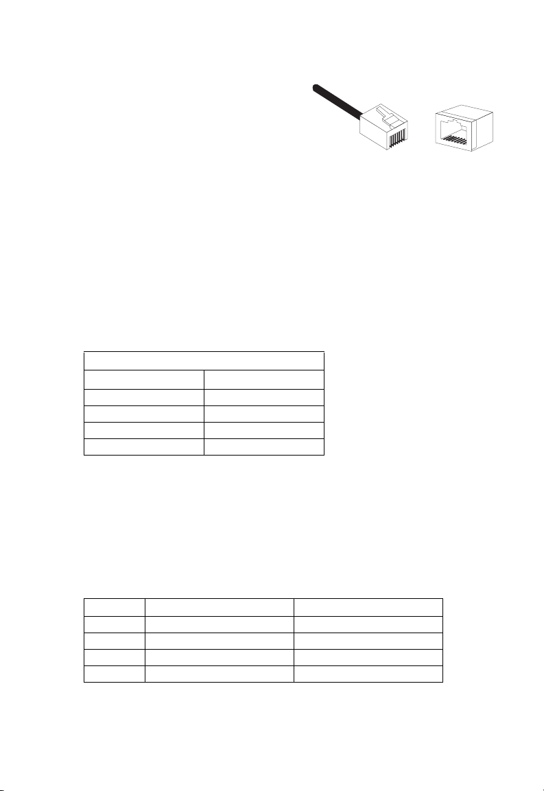
Making a Connection to an RJ-45 Port
The RJ-45 ports on the switch supp or t aut om at i c M D I /MDI-X operation, so you can
use standard straight-thro ugh twisted-pair cables to connec t to an y ot he r network
device (PCs, servers, switches, routers, or hubs).
Note: If auto-negotiation is disabled for an RJ-45 port, the auto-MDI/MDI-X pin signal
configuration is also disabled.
1. Prepare the network devices you wish to network. Make sure you have installed
10BASE-T or 100BASE-TX network interfac e car ds for connecting to the
switch’s RJ-45 station ports.
2. Prepare straight-through shielded or unshielded twisted-pair cables with RJ-45
plugs at both ends. Use 100 -o hm C at egory 3, 4 or 5 cable for standard
10 Mbps Ethernet connectio ns, or 100-ohm Category 5 cable for 1 00 M bps
Fast Ethern et connections.
3. Connect one end of the ca ble to th e R J- 45 port of the network interface ca rd,
and the other end to any available RJ-45 port on the switch. All RJ- 45 por ts
support 10 Mbps and 100 Mbps Eth er net connections. When ins erting an
RJ-45 plug, be sure the tab on the plug clicks into position to ensure that it is
properly seated. Using the switch in a stand-alone configuration, you can
network up to 48 end nodes .
Caution: Do not plug a phone jack connector into any RJ-45 port. This may damage the
Notes: 1. When connecting to another compatible switch or hub with auto-negotiation
Restrictions on Cascade Length - The IEEE 802. 3 stan dar d r ecommends
restricting the number of hubs (i.e., repeaters) cascad ed v ia twist ed-pair cable to 4;
switch. Instead, use only twisted-pair cables with RJ-45 connectors that
conform with FCC standards.
disabled, use straight-through cable to connect to an MDI port on the other
device. You may also attach to
crossover cabling. (Refer to “Port
description of crossover cable.)
2. Make sure each twisted-pair cable does not exceed 100 meters (328 feet).
3. We advise using Category 5 cable for all network connections to avoid any
confusion or inconvenience in the future when you upgrade attached devices
to Fast Ethernet.
MDI-X station ports at both ends if you use
and Cable Assignments” on page 17 for a
7
Page 14

OmniStack® 6148
while IEEE 802.3u provides even stricter recommendati ons fo r Fa st Eth er net .
Therefore, when cascading devices other than this switch, please refer to the
accompanying docum entati on for cascade restrictions . However, note that because
switches break up the path for connected devices into separat e collision domains,
you should not include the
switch or connected cabling in your calculations for
cascade length involving other devices.
Connecting to a 100BASE-FX Port
100BASE-FX Module
TXTXRX RX
If you connect fiber cabl e t o th e
100BASE-FX module, be sure you use an
SC-type connector. When inserting the cable, be sure the tab on the plug clicks into
position to ensure that it is pro per l y seated. If you use an SC-to-ST co nverter, run
cable from the Rx (Tx) port on the module to the Tx (Rx) port on the target device.
Note that the fiber optic po rts oper at e only at 100 Mbps, full duplex. In this mo de,
you can run a fiber optic link up to 2 kilometers (1.24 miles).
Caution: The media expansion modules are not hot-swappable. Be sure you power off
the switch before installing any of these modules.
Note: As a general rule, the length of fiber optic cable for a single switched link should
not exceed 2 kilometers (1.24 miles). However, budget constraints must also be
considered when calculating the maximum cable length for your specific
environment.
Connecting to a Gigabit Fiber Optic
1000BASE-SX Module
RX
TX
Port
When connecting fiber c abl e t o a Gi gabit
fiber-optic port on the swi t ch, be sure you
use an SC-type connector. Follow the steps
GBIC Module
1000Base X
TXRX
below.
Warning:This switch uses lasers to transmit signals over fiber optic cable. The lasers are
compliant with the requirements of a Class 1 Laser Product and are inherently
eye safe in normal operation. However, you should never look directly at a
transmit port when it is powered on.
1. Remove and keep the SC port’s rubber cover. When not connected to a fiber
cable, the rubber cove r sh ould be replaced to protect the opt ic s.
2. Check that the fiber t erminator s are clean. You can clean the cable plugs by
wiping them gently with a cl ean tissue or cotton ball moist en ed w i t h a little
ethanol. Dirty fiber terminat ors on fib er o pti c cabl es will impair the quality of the
light transmitted through the cable and lead to degraded performance on the
port.
3. Connect one end of the cable to the SC port on the switch and the other end to
the SC port on the other device. Since SC connectors are keyed, the cable can
be attached in only one orientation . W he n in serting the cable, be sure the tab
on the plug clicks into position to ensure that it is properly seated.
8
Page 15

Installing the Switch
All the SC-type ports operate at 100 0 Mbps with support for auto-negotiation of
duplex mode (full/half) and f low control. Also note the maximum len gt h f or
1000BASE-SX and 1000BASE- LX fiber optic cable depends on the core size an d
the rating of the cable, as sh ow n in t he f ol l owi ng tables.
Maximum 1000BASE-SX Gigabit Ethernet Cable Length
Fiber Size Fiber Bandwidth Maximum Cable Length
62.5/125 micron
multimode fiber
50/125 micron
multimode fiber
160 MHz/km 2-220 m (7-722 ft)
200 MHz/km 2-275 m (7-902 ft)
400 MHz/km 2-500 m (7-1641 ft)
500 MHz/km 2-550 m (7-1805 ft)
Maximum 1000BASE-LX Gigabit Ethernet Cable Length
Fiber Size Fiber Bandwidth Maximum Cable Length
9/125 micron
N/A 2 m - 5 km (7 - 16404 ft)
singlemode fiber
Connecting to a 1000BASE-T Port
To connect to a 1000BASE-T port, use
Category 5 or 5e cable. The ma xi m um
1000BASE-T Module
1000BASE-T
X
10
100
1000
cable length is 100m (328 feet). You
should test the cable installation for IE EE 802.3ab compliance. See “1000BASE-T
Cable Requirements” on page 18. Note that this module operates at 10, 100 or
1000 Mbps with support for auto-negotiation of duplex mode (full/half), speed, and
flow control.
There are 3 LEDs on the front panel of the 1000BASE-T m odule to indi cate
communication speed. Their status is shown in the follow i ng table .
LED State Indication
10 On Communications have been set to 10 Mbps.
100 On Communications have been set to 100 Mbps.
1000 On Communications have been set to 1000 Mbps.
Powering On the Switch
1. Plug the power cord into the power socket on the rear of the switch, and the
other end into a power outle t. (If you have purchased a redund ant power
supply, plug it into the “DC INPUT” receptacle on the rear of the s w itc h. )
2. Check the LED marked Pow er on the front panel to see if it is on. The unit w ill
automatically select th e set t in g that m at ches the connected inpu t vo ltage.
Therefore, no additional adj ustments are necessary when connecting it to any
input voltage within the range m ar ked on the rear panel.
3. The switch performs a sel f-di ag nostic test upon power-on. (N ot e t hat thi s te st
takes several minutes to c om pl et e.)
Note: The unit supports a “hot remove” feature which permits you to connect or
disconnect twisted-pair or fiber cables without powering off the switch and without
disrupting the operation of the devices attached to the switch.
9
Page 16

OmniStack® 6148
Verifying Port Status
Check each connec tio n by viewing the port indica t or s on the base unit front panel.
Their status is shown in the follow in g table.
LED State Indication
System
Power On Switch is receiving power.
RDP On Redundant power unit on.
Mgmt On Management agent operational.
RJ-45 Ports
Link On Port has established a valid network connection.
Activity* On Traffic is passing through the port.
FDX* On Port has been set to full duplex.
FC* On Flow control enabled.
Module Ports
Status On A valid module is correctly installed in the slot.
Activity On Traffic is passing through the port.
* Use the Mode Select button to select LED displ ay mode.
Yellow Communications have been set to 10 Mbps.
Green Communications have been set to 100 Mbps.
Flashing Port has been manually disabled, or partitioned
by the system due to excessive errors.
Verifying System Operation
Verify that the stack has at least one Management Module correctly installed and
operating. The “Mgmt” LED on the switch that contains the M an agement Module
should be on, indicating th at the m odule is installed and operating corr ect l y.
Verify that the stack connections are operating correctly. Each switch in the stack
has it’s own unique unit ID (a numb er from 1 to 3) dis pl ay ed by the front-panel LCD
labeled “Switch ID.” The switch that contains the master Management Module and a
Redundant Stacking Module always has the unit ID “1.” If any switch in th e stack
displays a flashing or un stable unit ID for more than 30 seco nds, you should check
the following items:
• Reset the stack by powering off all switches and the n powering them back on.
• Be sure that all Stacking Modules are correctly installed in each switch’s lower-left
slot and the stacking cables are properly attached.
Ve r i fy that any opt ional modul es are installed corr ectly. The Mod ule 1 or Module 2
“Status” LEDs on the switch panel should be on, indi cating that the modules are
installed and operating correctly.
Verify that all attached devices have a valid connection. The switch monitors the link
status for each port. If any devic e is pr operly connected to the switc h and
transmitting a link signa l, the Li nk indicator will light up for the corresponding port. If
the Link indicator fails to light w hen you connect a device to th e sw it ch, check the
following items:
10
Page 17

Installing the Switch
• Be sure all network cables and connectors are properly attached to the connected
device and the switch.
• See if your cable is function ing pr operly by using it for another por t an d at t ach ed
device that displays val i d indi cations when connecte d to the net w or k.
• Be sure no twisted-pair cable exceeds 100 meters (328 feet). 100 Mbps fiber cable
should be under 2 kilomet er s (1 .2 4 m i les) . Th e m aximum length for fiber op tic
Gigabit connections is listed in the table on the preceding pa ge.
Applications
This switch segments your ne two rk , sig ni fic ant ly i ncreasing both bandwidth and
throughput. Any port on the switch can be attached to a hub (a shared collision
domain) or provide a dedi cated link to a single network device (such as a
workstation or server). When a port on the switch is connected to a hub (a 10 or 100
Mbps repeater), the bandwi dth provided by that port is shared by all th e devices
connected to the attached hub. However, when a port is connected to an end n ode
or to a device that breaks up the collision domain (e.g., anot her switch, bridge or
router), the attached devic e has access to the full bandwidth provided by that port.
Bridging Functions - This switch provides fully t ra nspar ent bridging functions.
It automatically learns nod e addresses, that are subsequently used to filter and
forward all traffic based on the destination address. Wh en t ra ffic passe s between
devices attached to the sa m e shared collision domain, those packets are filtered
from the switch. But when tr affic mus t b e passed between unique segm ents (i.e .,
different ports on the switch), the high-speed switching fabric fo rwards the packets
at near zero latency.
Switching Functions - Store-and-forward switchi ng is u sed to forward traffic to
other ports. This scheme ensur es data integrity and provides a clea n data stream.
Flexible Configuration - This switch is not only designed to segment your network,
but also to provide a wide range of options in setting up network connections. It can
be used as a simple stand-alone switch; stacked up to three high; or connected with
standard repeater hubs, sw i tc hes, or other network interconnection devices in
various configuratio ns .
Media Expansion Options - You can use a Fast Ethernet fiber module to connect
to remote sites up to 2 kilome t er s (1 .2 4 m iles) away, or a Gigabit module to support
applications such as high-speed file servers, or for connecting to a collapsed Gigabit
backbone switch.
11
Page 18

OmniStack® 6148
Servers
OmniStack 6148
Stack
1
Switch at remote site
1
(via 100BASE-FX link)
1
1
Collapsed Backbone
(via Gigabit link)
...
10 Mbps
Hub Stack
...
100 Mbps
Hub Stack
12
Page 19

Product Specifications
Product Specifications
Base Unit
Physical Characteristics
Access Method CSMA/CD
Standards Conformance IEEE 802.3, IEEE 802.3u
Communication Rate 10/100 Mbps
Communication Mode Full or half duplex
Media Supported 10BASE-T - 100-ohm Category 3,4,5 twisted-pair cable
100BASE-TX - 100-ohm Cate gory 5 twisted-pair cable
Number of Ports 48 RJ-45 100BASE-TX po rts
Indicator Panel System: Power, RDP, Mgmt; Ports: link/speed/disabled/
partitioned, activity, duplex, flow control
Dimensions 440 x 305 x 64 mm (17.37 x 12 x 2. 53 in.)
Weight 4.96 kg (10.93 lb)
Input Power Full range: 100 to 240 V (±10% ), 50 t o 60 Hz (±3 Hz)
Maximum Current 2 A
Power Consumption 70 Watts max. @ 100-240 VAC
Heat Dissipation 239 BTU/hr max. @ 100-240 VAC
Temperature Operating: 0~50 °C / 32 ~12 2 °F
Humidity 10% to 90% (noncondensing)
Certification CE Mark
Emissions FCC Class A, VCCI Class A, CISPR Class A,
Immunity IEC 61000-4-2/3/4/5 /6 /11
Safety CSA/NRTL, TÜV/GS
Switching Criteria
Network Bridging Function Filtering, forwarding and learning
Switching Method Store-and-forward
Address Table 8K entries total
Queue Buffer 30.7K bytes per 10/ 100 Mbps port
Address Resolution Fast hashing scheme
Traffic Control
Flow Control Back pressure for half duplex
Broadcast Suppression Broadcast traffic suppressed at configura bl e t hr eshold
max.@110 V, 3 A
RMS
Storage: -40~70 °C / -40~158 °F
EN 61000-3-2/3
2M bytes for 1000 Mbps port
IEEE 802.3x for full duplex
max.@240 V
RMS
13
Page 20

OmniStack® 6148
Modules
Management Module (OS-6148-MNGT-KIT)
System Configuration Via console connection to seria l por t or vi a Telnet;
Web-based management via HTTP protocol to access
embedded managem ent program;
Full-featured SNMP/RMON management using
network management software
Management Agent MIB support: MIB II (RFC1213), Bridge MIB (RFC
1493), Ethernet-like MIB (RFC1643), RMON MIB
(RFC1757 ) , and Alcatel ’s private MIB
RMON Groups 1,2,3,9 (Statistics, History, Alarm, Event)
100BASE-FX Module (OS-6ESM-100FM-2)
Access Method CSMA/CD
Standards Conformance IEEE 802.3u 100BASE-FX
Communication Rate 100 Mbps
Communication Mode Full duplex
Media Supported 50/125 micron or 62.5/125 micron multimode fiber
Output Power Minimu m: -1 9 dBm, Maximum: -14 dBm
Receiver Sensitivity Minimum: -33 dBm, Saturation: -14 dBm
Power Budget 19 dB
Number of Ports 2 100BASE-FX SC-type ports
Indicator Panel Includ ed on base unit
1000BASE-T Module (OS-6GSM-T-1)
Access Method CSMA/CD
Standards Conformance IEEE 802.3ab
Communication Rat e 10 ,1 00 or 1000 Mbps
Communication Mode Full or half duplex
Media Supported C at egory 5 or 5e twisted-pair cable
Number of Ports 1 1000BASE-T RJ-45 port
Indicator Panel Includ ed on base unit, plus 10,100,1000 speed LEDs
1000BASE-SX Module (OS-6GSM-FM-1)
Access Method CSMA/CD
Standards Conformance IEEE 802.3z
Communication Rate 1000 Mbps
Communication Mode Full or half duplex
Media Supported 50/125 micron or 62.5/125 micron multimode fiber
Output Power Minimum: -9.5 dBm, Maximum: -4 dBm
Receiver Sensitivity Minimum: -20 dBm, Saturation: -3 dBm
Power Budget 16 dB
Number of Ports 1 1000BASE-SX (SC-type) port
Indicator Panel Includ ed on base unit
1000BASE-LX Module (OS-6GSM-FS-1)
Access Method CSMA/CD
Standards Conformance IEEE 802.3z
14
Page 21

Troubleshooting
Communication Rate 1000 Mbps
Communication Mode Full or half duplex
Output Power Minimum: -9.5 dBm, Maximum: -3 dBm
Receiver Sensitivity Minimum: -20 dBm, Saturation: -3 dBm
Power Budget 17dBm
Media Supported 9/125 micron singlemode fiber
Number of Ports 1 1000BASE-LX (SC-type) port
Indicator Panel Includ ed on base unit
GBIC Module (OS-6GSM-GBIC-1)
Access Method CSMA/CD
Standards Conformance IEEE 802.3z
Communication Rate 1000 Mbps
Communication Mode Full or half duplex
Media Supported 50/125 micron or 62.5/125 micron multimode fiber
9/125 micron single-mo de fiber cable
Number of Ports 1 slot for GBIC transceivers
Indicator Panel Includ ed on base unit
Note: Contact the GBIC transceiver vendor for information on output power, receiver
sensitivity and power budget.
Stacking Module (OS-6STK-KIT)
Number of Ports Two 68-pin, SCSI connectors
Cable Type SCSI Type 4, length 30 cm
Backplane Bandwidth 9.6 Gbps
Redundant Stacking Module (OS-6100-RST-KIT)
Number of Ports Two 68-pin, SCSI connectors
Push Button Enables/disables clos ed-loop function for stack
Cable Type SCSI Type 4, length 1 m
Backplane Bandwidth 9.6 Gbps
Troubleshooting
Diagnosing Switch Indicators
The switch can be easily monitored through panel indicator s t o assist the network
manager in identifying problems. This table below describes common problems you
may encounter and po ssi bl e solutions.
15
Page 22

OmniStack® 6148
Symptom Cause Solution
Power indicator
does not light up
after power on.
Link indicator
does not light up
after making a
connection.
Mgmt indicator
does not light up
after power on.
Module 1/2 Status
indicator does not
light up af t e r po w er
on.
Switch ID LCD
does not display a
stable unit number.
Power outlet, power
cord, or internal power
supply may be
defective.
Network interface (e.g.,
a network adapter card
on the attached
device), network cable,
or switch port may be
defective.
A Management Module
is not installed
correctly, or may have
failed.
An optional module is
not installed correctly,
or may have failed.
The switch stack has
not initiated properly.
Check the power outlet by plugging in another device
that is functioning properly. Check the power cord with
another device. If these measures fail to resolve the
problem, contact your Alcatel distributor.
Verify that the switch and attached device are
powered on. Be sure the cable is plugged into both the
switch and corresponding device. Verify that the
proper cable type is used and its length does not
exceed specified limits. Check the adapter on the
attached device and cable connections for possible
defects. Replace the defective adapter or cable if
necessary.
Check that the Management Module is correctly
installed in the upper slot on the switch rear panel (at
least one Management Module is required in a switch
stack). Test the Management Module by installing it in
another switch unit. If these measures fail to resolve
the problem, contact your Alcatel distributor.
Check that the module is correctly installed in one of
the two lower slots on the switch rear panel. Test the
module by installing it in another switch unit. If these
measures fail to resolve the problem, con tac t your
Alcatel distributor.
Reset the stack by powering off each switch unit in the
stack and then powering them back on. Check all
Stacking Modules are installed correctly in the
lower-left slot on the rear panel of each switch. Check
that all stacking cables are connected correctly. If
these measures fail to resolve the problem, contact
your Alcatel distributor.
Power and Cooling Problems
If the power indicator does not turn on when the power cor d is pl ugg ed i n, you may
have a problem with the pow e r ou tlet , pow e r c ord, or internal power supply as
explained in the previou s se ct i on. H owever, if the unit powers off after running for a
while, check for loose power connections, power losses or surges at the power outlet,
and verify that the fans on the right side of the unit are unobstructed and running
prior to shutdown. If you still cannot isolate the problem, then the internal power
supply may be defecti ve. In this case, contact your Alca t el dis t ri butor for assistance.
Installation
Verify that all system components have been pr operly installed. If one or more
components appear to be m al functioning (e.g., the power co rd or network cabling),
test them in an alternate envi r onment where you are sure th at all the ot her
components are functioning properly.
16
Page 23
Port and Cable Assignments
Port and Cable Assignments
RJ-45 Port Description
Caution: DO NOT plug a phone jack connector
into any RJ-45 port. Use only
twisted-pair cables with RJ-45
connectors that conform with FCC
standards.
For 100BASE-TX/10BASE-T connections, a twisted-pair cable must have two pairs
of wires. Each wire pair is identified by t wo di fferen t color s. For example, one wire
might be red and the other, red with white stripes. Also, an RJ-45 connector must be
attached to both ends of the cab l e.
Caution: Each wire pair must be attached to the RJ-45 connectors in a specific
orientation.
10BASE-T/100BASE-TX Pin Assignments
With 100BASE-TX/10BASE-T cable, pins 1 and 2 are used for transmitting data, and
pins 3 and 6 for r eceiving data.
RJ-45 Pin Assignments
Pin Number
1Tx+
2Tx3Rx+
6Rx-
1: The “+” and “-” signs represent the polarity of the wires
that make up each wire pair.
Assignment
1
8
1
8
1
Because all ports on this switch support automatic MDI/M DI -X operation, you can
use straight-through cables for all network connections to PCs or servers, or to other
switches or hubs. In straight-through cable, pins 1, 2, 3, and 6, at one end of the
cable, are connected str ai gh t through to pins 1, 2, 3 and 6 at the other end of the
cable. The table below shows the 10BASE-T/100BASE- TX M DI and MDI-X por t
pinouts.
Pin MDI-X Assignment MDI Assignment
1 Input Receive Data + Output Transmit Data +
2 Input Receive Data - Output Transmit Data 3 Output Transmit Data + Input Receive Data +
6 Output Transmit Data - Input Receive Data -
No other pins are used.
Note: If auto-negotiation is disabled for an RJ-45 port, the auto-MDI/MDI-X pin signal
configuration is also disabled.
17
Page 24

OmniStack® 6148
1000BASE-T Pin Assignments
The table below shows the 1000BASE-T MDI and MDI-X port pinouts. These ports
require that all four pairs of wires be connected. Note that for 1000BASE-T
operation, all four pairs of wires ar e used for both transmit and rece ive.
Use 100-ohm Categor y 5 or 5e unshielded twisted-pair (UTP) or sh ie lded
twisted-pair (STP) cable for 1000BASE-T connections. Also be sure that the length
of any twisted-pair connection does not exceed 100 meter s (3 28 feet).
Pin MDI Signal Name MDI-X Signal Name
1 Transmit Data plus (TD1+) Transmit Data plus (TD2 +)
2 Receive Data minus (RD1-) Receive Data minus (RD2-)
3 Transmit Data plus (TD2+) Transmit Data plus (TD1+)
4 Transmit Data plus (TD3+) Transmit Data plus (TD4+)
5 Receive Data minus (RD3-) Receive Data minus (RD4-)
6 Receive Data minus (RD2-) Receive Data minus (RD1-)
7 Transmit Data plus (TD4+) Receive Data minus (RD3+)
8 Receive Data minus (RD4-) Receive Data minus (RD3-)
1000BASE-T Cable Requirements
All Category 5 UTP cables that are used for 100 BASE-TX connections should also
work for 1000BASE-T, providing that all four wire pairs are connected. However, it is
recommended tha t for all cr itical connections, or any ne w cable installations,
Category 5e (enhance d C at eg ory 5) cable should be used. The Cat egory 5e
specification include s te st param eters that are only recommendations for Category
5. Therefore, the first step in pre paring existing Category 5 cabling f or run ni ng
1000BASE-T is a simple test of the cable installation to be sure that it complies with
the IEEE 802.3ab standards.
Cable Testing for Existing Category 5 Cable
Installed Category 5 cabling must pass tests for Attenuation, Near-End Crosstalk
(NEXT), and Far-End Crosstalk (FEXT). This cable testing information is specified in
the ANSI/TIA/EIA-TSB-67 standard. Additionally, cables must also pass test
parameters for Return Loss and Equal-Level Far-End Crosstalk (ELFEXT). These
tests are specified in the ANSI/TIA/EIA - TSB-95 Bulletin, “The Additional
Transmission Performance Guidelines for 100 Ohm 4-Pair Category 5 Cabling.”
Note that when testing your cable installation, be sure to incl ude all patch cables
between switches and end devices.
Adjusting Existing Category 5 Cabling
If your existing Category 5 installation does not meet one of th e te st parameters for
1000BASE-T, there are basically three measures that can be applied to try to correct
the problem:
1. Replace any Category 5 patch cables with high-perform ance Category 5e
cables.
2. Reduce the number of connectors used in the link.
3. Reconnect some of th e connectors in the link.
18
Page 25

EMI Certification
EMI Certification
FCC Class A Certification (USA)
Warning: This equipment generates, uses, and can radiate radio frequency energy
and, if not installed and used in accordance with the instruction manual, may caus e
interference to radio communica t ions. It has be en tested and fo und to comply with
the limits for a Class A digital device pursuant to Subpart B of Part 15 of FCC Rules,
which are designed to provide reasonable protection against such interference when
operated in a commerci al environment. Operation of thi s eq ui pm ent in a residential
area is likely to cause interfer ence, in which case the user, at his own expense, w i ll
be required to take whatever m easures are required to correct the interference.
You may use unshielded twist e d- pair (UTP) for RJ-45 connections - Cat egory 3 or
greater for 10 Mbps connec t ions, C at egory 5 for 100 Mbps connections and
Category 5 or 5e for 1000 M bps con nections. For fiber optic con nections, you may
use 50/125 or 62.5/125 m icr on m ul t i m ode fiber, or 9/125 micron single-mode fiber.
Canada Department of Communications - Class A
This digital apparatus does not exceed the Class A limits for radio noise emissions
from digital apparatus as set out in the interference-causing equipment standard
entitled “Digital Apparatus,” ICES-003 of the Department of Communications.
Cet appareil num
aux appareils num
brouilleur: “Appareils Num
Communications.
érique respecte les limites de bruits radioélectriques applicables
ériques de Classe A prescrites dans la norme sur le matériel
érques,” NMB-003 édictée par le ministère des
BSMI Class A (Taiwan)
VCCI Class A Compliance (Japan)
19
Page 26

OmniStack® 6148
CE Mark Declaration of Conformance for EMI and Safety (EEC)
This information techn ology equipment complies wit h th e re quirements of the
Council Directive 89/336/EEC on the Approximation of the laws of the Member
States relating to Electromagnetic Compatibility an d 73/23/EEC for electrical
equipment used within certain voltage limits and the Amendment Directive 93/68/
EEC. For the evaluation of the com pl iance with these Directives, the foll owi ng
standards were applied:
RFI
Emission:
Immunity: • Product family standard according to EN 55024:199 8
LVD: • EN 60950 (A1/1992; A2/1993; A3/1993; A4/1995; A11/1997)
• Limit class A according to EN 55022:1998
• Limit cl ass A for harmon ic current emission acco rding to
EN 61000-3-2/1995
• Limitation of voltage fluc tu at ion and flicker in low-voltage
supply system accord in g t o EN 61000-3-3/1995
• Electrostatic Discharge according to EN 61000-4-2:1995
(Contact Discharge: ±4 kV, Air Discharge: ±8 kV)
• Radio-frequency ele ct ro m agnetic field according to
EN 61000-4-3:1996
(80 - 1000 MHz with 1 kHz AM 80 % Mo dul a tion: 3 V/m)
• Electrical fast transient/burst according to EN 61000-4-4:1995
(AC/DC p o wer supply: ±1 kV, Data/Signa l lines: ±0 . 5 k V)
• Surge immunity test according to EN 61000-4-5:1995
(AC/DC Line to Line: ±1 kV, AC/ D C Li ne to Earth: ±2 kV)
• Immunity to conducted di sturbances, Induced by
radio-frequency fields: EN 61000-4-6:1996
(0.15 - 80 MHz with 1 kHz AM 80% Modulation: 3 V/m)
• Power frequency mag net i c f ield imm unity test according to
EN 61000-4-8:1993
(1 A/m at frequency 50 Hz )
• Voltage dips, short inter ru pt i ons and voltage variations
immunity test according to EN 61000-4-11:1 994
(>95% Reduction @10 m s, 30% Reduction @500 ms, > 95%
Reduction @5000 ms)
Warning! Do not plug a phone jack con nec to r in t he R J -4 5 port. This may damage
this device. Les raccordeurs ne sont pas utilisé pour le sy st èm e téléphonique!
20
Page 27
Safety Compliance
Safety Compliance
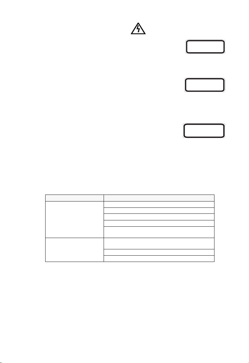
Warning: Fiber Optic Port Safety
When using a fiber optic media expansion module, never look at
CLASS I
LASER DEVICE
the transmit laser while it is powered on. Also, never look directly
at the fiber TX port and fiber cab le ends w hen they are powered on.
Avertissment: Ports pour fibres optiques sécurité sur le plan optique
DISPOSITIF LASER
DE CLASSE I
Ne regardez jamais le laser tant qu’il est sous tension. Ne
regardez jamais directe m ent le port TX (Transmission) à fibres optiq ues et les
embouts de câbles à fibres op tiques tant qu'ils sont sous tension.
Warnhinweis: Faseroptikanschlüsse Optische Sicherheit
LASERGER
DER KLASSE I
ÄT
Niemals ein Übertragungslaser betrachten, während dieses
eingeschaltet ist. Niema ls di re kt auf den Faser-TX-Anschluß und auf die
Faserkabelenden sc hau en, w ährend diese eingeschalte t s ind.
Underwriters Laboratories Inc. (USA)
Important! Before making connections, make sure you have the correct Cord Set.
Check it (read the label on the cabl e) against the following speci fica tion list.
Operating Voltage Cord Set Specifications
120 Volts UL Listed/CSA Certified Cord Set
240 Volts (Europe only) Cord Set with H05VV-F cord having three conductors
Minimum 18 AWG
Type SVT or SJT three conductor cord
Maximum length of 15 feet
Parallel blade, grounding type attachment plug rated
15 A, 125 V
with minimum diameter of 0.75 mm
IEC-320 receptacle
Male plug rated 10 A, 250 V
2
21
Page 28

OmniStack® 6148
Wichtige Sicherheitshinweise (Germany)
1. Bitte lesen Sie diese Hinweise sorgfältig durch.
2. Heben Sie diese Anleitung für den späteren Gebrauch auf.
3. Vor jedem Reinigen ist das Gerät vom Stromnetz zu trennen. Verwenden Sie keine
Flüssigoder Aerosolreiniger. Am besten eignet sich ein angefeuchtetes Tuch zur Reinigung.
4. Die Netzanschlu ßsteckdose soll nahe dem Gerät angebracht und leicht zugänglich sein.
5. Das Gerät ist vor Feuchtigkeit zu schützen.
6. Bei der Aufstellung des Gerätes ist auf sicheren Stand zu achten. Ein Kippen oder Fallen
könnte Beschädigungen hervorrufen.
7. Die Belüftungsöffnungen dienen der Luftzirkulation, die das Gerät vor Überhitzung
schützt. Sorgen Sie dafür, daß diese Öffnungen nicht abgedeckt werden.
8. Beachten Sie beim Anschluß an das Stromnetz die Anschlußwerte.
9. Verlegen Sie die Netzanschlußleitung so, daß niemand darüber fallen kann. Es sollte
auch nichts auf der Leitung abgestellt werden.
10. Alle Hinweise und Warnungen, die sich am Gerät befinden, sind zu beachten.
11. Wird das Gerät über einen längeren Zeitraum nicht benutzt, sollten Sie es vom Stromnetz
trennen. Somit wird im Falle einer Überspannung eine Beschädigung vermieden.
12. Durch die Lüftungsöffnungen dürfen niemals Gegenstände oder Flüssigkeiten in das
Gerät gelangen. Dies könnte einen Brand bzw. elektrischen Schlag auslösen.
13. Öffnen sie niemals das Gerät. Das Gerät darf aus Gründen der elektrischen Sicherheit
nur von authorisiertem Servicepersonal geöffnet werden.
14. Wenn folgende Situationen auftreten ist das Gerät vom Stromnetz zu trennen und von
einer qualifizierten Servicestelle zu überprüfen:
a. Netzkabel oder Netzstecker sind beschädigt.
b. Flüssigkeit ist in das Gerät eingedrungen.
c. Das Gerät war Feuchtigkeit ausgesetzt.
d. Wenn das Gerät nicht der Bedienungsanleitung entsprechend funktioniert oder Sie
mit Hilfe dieser Anleitung keine Verbesserung erzielen.
e. Das Gerät ist gefallen und/oder das Gehäuse ist beschädigt.
f. Wenn das Gerät deutliche Anzeichen eines Defektes aufweist.
15. Zum Netzans chluß dies es Gerät es ist eine geprüfte Leitung zu verwenden. F ür einen
Nennstrom bis 6 A und einem Gerätegewicht größer 3 kg ist eine Leitung nicht leichter
als H05VV-F, 3G, 0.75 mm
Der arbeitsplatzbezogene Schalldruckpegel nach DIN 45 635 Teil 1000 beträgt 70 dB(A) oder
weniger.
2
einzusetzen.
Optional Hardware
OS-6148-MGT-KIT: SNMP/RMON Management Module with RS -2 32 Port
OS-6ESM-100FM-2: Media Module with 2 100BASE-FX (SC-type) Ports
OS-6GSM-FM-1: Media Module with 1 1000BASE-SX (SC-type) Port
OS-6GSM-FS-1: Media Module with 1 1000BASE-LX (SC-type) Por t
OS-6GSM-T-1: Media Module with 1 1000BASE-T Port
OS-6GSM-GBIC-1: Media Module with 1 GBIC slot
OS-6STK-KIT: Stacking Module kit in cl ud in g 30 cm stacking cable
OS-6100-RST-KIT : Redundant Stacking Module kit including 1 m stacking cable
RDP-150-AC Backup power to a single O S- 6148
22
Page 29

Page 30

150200007000A
E072002-R01
 Loading...