

Alcatel-Lucent OmniSwitch 6400-U24, OmniSiwtch 6400 U24D, OmniSwitch 6400-48, OmniSwitch 6400-P48, OmniSwitch 6400-24 Hardware User's Manual
...
Part No. 060236-10, Rev. A
August 2008
OmniSwitch 6400 Series
Hardware Users Guide
www.alcatel-lucent.com

This user guide documents OmniSwitch 6400 Series hardware, including chassis and associated
components. The specifications described in this guide are subject to change without notice.
©
Copyright
or in part without the express written permission of Alcatel-Lucent.
Alcatel-Lucent
OmniSwitch
OmniAccess™, Omni Switch/Router™, PolicyView™, RouterView™, SwitchManager™, VoiceView™,
WebView™, X-Cell™, X-Vision™, and the Xylan logo are trademarks of Alcatel-Lucent.
This OmniSwitch product contains components which may be covered by one or more of the following
U.S. Patents:
2008 by Alcatel-Lucent. All rights reserved. This document may not be reproduced in whole
®
and the Alcatel-Lucent logo are registered trademarks of Alcatel-Lucent. Xylan®,
®
, OmniStack®, and Alcatel-Lucent OmniVista® are registered trademarks of Alcatel-Lucent.
• U.S. Patent No. 6,339,830
• U.S. Patent No. 6,070,243
• U.S. Patent No. 6,061,368
• U.S. Patent No. 5,394,402
• U.S. Patent No. 6,047,024
• U.S. Patent No. 6,314,106
• U.S. Patent No. 6,542,507
• U.S. Patent No. 6,874,090
26801 West Agoura Road
Calabasas, CA 91301
(818) 880-3500 FAX (818) 880-3505
support@ind.alcatel.com
US Customer Support—(800) 995-2696
International Customer Support—(818) 878-4507
Internet—service.esd.alcatel-lucent.com
ii OmniSwitch 6400 Series Hardware Users Guide August 2008

Contents
About This Guide .......................................................................................................... ix
Supported Platforms .......................................................................................................... ix
Who Should Read this Manual? ........................................................................................xi
When Should I Read this Manual? ....................................................................................xi
What is in this Manual? ..................................................................................................... xi
What is Not in this Manual? ..............................................................................................xi
How is the Information Organized? .................................................................................xii
Documentation Roadmap .................................................................................................xii
Related Documentation ...................................................................................................xiv
Published / Latest Product Documentation ...................................................................... xv
Technical Support ............................................................................................................ xv
Chapter 1 OmniSwitch 6400 Series ...........................................................................................1-1
OmniSwitch 6400 Series Chassis Configurations ...........................................................1-2
Availability Features .......................................................................................................1-3
Software Rollback ....................................................................................................1-3
Backup Power Supplies ............................................................................................1-3
Hot Swapping ...........................................................................................................1-4
Hardware Monitoring ...............................................................................................1-4
Chapter 2 OmniSwitch 6400 Series Chassis and Hardware Components .....................2-1
OmniSwitch 6400 Series Chassis Configurations ...........................................................2-1
OmniSwitch 6400-24 Front Panel ............................................................................2-2
OmniSwitch 6400-24 Rear Panel .............................................................................2-3
OS6400-24 Specifications ........................................................................................2-4
OmniSwitch 6400-P24 Front Panel ..........................................................................2-5
OmniSwitch 6400-P24 Rear Panel ...........................................................................2-6
OS6400-P24 Specifications ......................................................................................2-7
OmniSwitch 6400-U24 Front Panel .........................................................................2-8
OmniSwitch 6400-U24 Rear Panel ..........................................................................2-9
OS6400-U24 Specifications ...................................................................................2-10
OmniSwitch 6400-U24D Front Panel ....................................................................2-11
OmniSwitch 6400-U24D Rear Panel .....................................................................2-12
OS6400-U24D Specifications ................................................................................2-13
OmniSwitch 6400-48 .............................................................................................2-14
OmniSwitch 6400-48 Rear Panel ...........................................................................2-15
OS6400-48 Specifications ......................................................................................2-16
OmniSwitch 6400-P48 Front Panel ........................................................................2-17
OmniSwitch 6400 Series Hardware Users Guide August 2008 iii

Contents
OmniSwitch 6400-P48 Rear Panel .........................................................................2-18
OS6400-P48 Specifications ....................................................................................2-19
LED Status Indicators ...................................................................................................2-20
OmniSwitch 6400 Series Power Supplies .....................................................................2-21
PS-510W-AC Power Supply ..................................................................................2-22
PS-360W-AC Power Supply ..................................................................................2-23
PS-126W-AC Power Supply ..................................................................................2-24
PS-120W-DC Power Supply ..................................................................................2-25
126W AC Internal Power Supply ...........................................................................2-26
120W DC Internal Power Supply ...........................................................................2-26
Power Supply Shelf ................................................................................................2-27
AC Power Cords ...........................................................................................................2-28
Specifications .........................................................................................................2-28
DC Power Specifications ..............................................................................................2-29
Console Port ..................................................................................................................2-30
Serial Connection Default Settings ........................................................................2-30
Modifying the Serial Connection Settings .............................................................2-30
Port Pinouts ............................................................................................................2-32
10/100 Ethernet Port – RJ-45 Pinout (non-PoE) .............................................2-32
Gigabit Ethernet Port – RJ-45 Pinout ..............................................................2-32
10/100/1000 Mbps Power over Ethernet Port – RJ-45 Pinout .......................2-32
RJ-45 Console Port – Connector Pinout ..........................................................2-33
Chapter 3 Mounting OS6400 Switches .....................................................................................3-1
General Mounting Recommendations .............................................................................3-1
Recommended Clearances .......................................................................................3-1
Elevated Operating Ambient Temperatures .............................................................3-2
Reduced Air Flow ....................................................................................................3-2
Mechanical Loading .................................................................................................3-2
Circuit Overloading ..................................................................................................3-2
Reliable Earthing ......................................................................................................3-2
Airflow Recommendations .............................................................................................3-3
Installation Overview ......................................................................................................3-4
Mounting Guidelines ................................................................................................3-4
Mounting Options ....................................................................................................3-4
Tabletop Installation ........................................................................................................3-5
Next Steps ................................................................................................................3-6
Rack-Mount Installation ..................................................................................................3-7
Rack Mount Guidelines ............................................................................................3-7
Rack Mounting Steps ...............................................................................................3-7
Next Steps ................................................................................................................3-8
Setting Up a Stacked Configuration ................................................................................3-9
Rack Mounting Stacked Configurations ..................................................................3-9
Cabling Stacked Configurations ...............................................................................3-9
Redundant Stacking Cable Connections ...........................................................3-9
Recommended Cabling Patterns ........................................................................3-9
iv OmniSwitch 6400 Series Hardware Users Guide August 2008

Contents
Installing Power Supplies ..............................................................................................3-12
Connecting a Power Supply to the Chassis ...................................................................3-12
Next Steps ..............................................................................................................3-13
Rack Mounting Power Supplies ....................................................................................3-14
Next Steps ..............................................................................................................3-17
Connecting Chassis to Power Source ............................................................................3-18
AC Power Supply Connections ..............................................................................3-18
Powering On a Chassis ....................................................................................3-18
DC Power Supply Connections ..............................................................................3-19
Connecting to a DC Power Source ..................................................................3-19
Hot-Swapping Power Supplies .....................................................................................3-22
Hot-Swapping a Power Supply Connected to the Rear of the Chassis ..................3-22
Hot-Swapping a Rack Mounted Power Supply ......................................................3-23
Chapter 4 Booting OmniSwitch 6400 Series Switches .........................................................4-1
Booting a Stand-Alone Switch ........................................................................................4-1
Booting Stacked Configurations .....................................................................................4-2
Monitoring the Chassis ...................................................................................................4-3
Checking the Overall Chassis Status ........................................................................4-3
Checking the Temperature Status ............................................................................4-3
Checking the Fan Status ...........................................................................................4-4
Checking the Power Supply Status ..........................................................................4-4
Additional Monitoring Commands ..........................................................................4-4
Using LEDs to Visually Monitor the Chassis ..........................................................4-4
Chapter 5 Managing Power over Ethernet (PoE) ...................................................................5-1
In This Chapter ................................................................................................................5-2
Power over Ethernet Specifications ................................................................................5-3
Viewing PoE Power Supply Status .................................................................................5-4
Configuring Power over Ethernet Parameters .................................................................5-5
Power over Ethernet Defaults ..................................................................................5-5
Understanding and Modifying the Default Settings .................................................5-5
Setting the PoE Operational Status ....................................................................5-5
Configuring the Total Power Allocated to a Port ..............................................5-6
Configuring the Total Power Allocated to a Switch .........................................5-6
Setting Port Priority Levels ...............................................................................5-7
Setting the Capacitor Detection Method ...........................................................5-8
Understanding Priority Disconnect .................................................................................5-9
Setting Priority Disconnect Status ............................................................................5-9
Disabling Priority Disconnect ...........................................................................5-9
Enabling Priority Disconnect ............................................................................5-9
Priority Disconnect is Enabled; Same Priority Level on All PD .....................5-10
Priority Disconnect is Enabled;
Incoming PD Port has Highest Priority Level .................................................5-10
Priority Disconnect is Enabled;
Incoming PD Port has Lowest Priority Level ..................................................5-10
OmniSwitch 6400 Series Hardware Users Guide August 2008 v

Contents
Priority Disconnect is Disabled .......................................................................5-11
Monitoring Power over Ethernet via CLI .....................................................................5-12
Chapter 6 Managing OmniSwitch 6400 Series Stacks ........................................................6-1
In This Chapter ................................................................................................................6-2
OmniSwitch 6400 Series Stack Overview ......................................................................6-3
Roles Within the Stack ....................................................................................................6-3
Primary and Secondary Management Modules .......................................................6-3
Primary Management Module Selection ...........................................................6-6
Secondary Management Module Selection .......................................................6-9
Idle Module Role ....................................................................................................6-11
Pass-Through Mode ...............................................................................................6-12
Recovering from Pass-Through Mode (Duplicate Slot Numbers) ..................6-13
Stack Redundancy and Failover ....................................................................................6-16
Checking Redundant Stacking Cable Status ..........................................................6-17
Slot Numbering .............................................................................................................6-18
Dynamic Slot Number Assignment ........................................................................6-19
Manual Slot Number Assignment ..........................................................................6-21
Reverting to the Dynamic Slot Numbering Model ..........................................6-22
Hot-Swapping Modules In a Stack ...............................................................................6-23
Removing Switches from an Existing Stack ..........................................................6-23
Inserting Switches Into an Existing Stack ..............................................................6-23
Merging Stacks .......................................................................................................6-24
Reloading Switches .......................................................................................................6-25
Reloading the Primary Management Module ........................................................6-25
Reloading the Secondary Management Module ....................................................6-27
Reloading Switches with Idle Roles .......................................................................6-29
Reloading Switches in Pass-Through Mode ..........................................................6-29
Reloading All Switches in a Stack .........................................................................6-30
Software Synchronization During a Full Reload .............................................6-30
Effects of Saved Slot Number Information on the Reload Process .................6-30
Avoiding Split Stacks .............................................................................................6-32
Changing the Secondary Module to Primary ................................................................6-33
Synchronizing Switches in a Stack ...............................................................................6-35
Automatic Synchronization During a Full Reload .................................................6-35
Monitoring the Stack .....................................................................................................6-36
Visually Monitoring the Stack ...............................................................................6-36
CLI Commands Supported on Both Primary and
Secondary Management Modules ..........................................................................6-37
Appendix A Regulatory Compliance and Safety Information ................................................7-1
Declaration of Conformity: CE Mark .............................................................................7-1
China RoHS: Hazardous Substance Table ......................................................................7-2
Waste Electrical and Electronic Equipment (WEEE) Statement ....................................7-4
vi OmniSwitch 6400 Series Hardware Users Guide August 2008

Contents
Standards Compliance .....................................................................................................7-5
Safety Agency Certifications ...................................................................................7-5
EMI/EMC Standards ................................................................................................7-5
FCC Class A, Part 15 ...............................................................................................7-6
Canada Class A Statement .......................................................................................7-6
JATE .........................................................................................................................7-6
CISPR22 Class A warning .......................................................................................7-6
VCCI ........................................................................................................................7-7
Class A Warning for Taiwan and Other Chinese Markets .......................................7-7
Translated Safety Warnings ............................................................................................7-8
Chassis Lifting Warning ....................................................................................7-8
Blank Panels Warning .......................................................................................7-8
Electrical Storm Warning ..................................................................................7-8
Installation Warning ..........................................................................................7-9
Invisible Laser Radiation Warning ....................................................................7-9
Lithium Battery Warning ................................................................................7-10
Operating Voltage Warning ............................................................................7-10
Power Disconnection Warning ........................................................................7-11
Proper Earthing Requirement Warning ...........................................................7-11
Read Important Safety Information Warning ..................................................7-12
Restricted Access Location Warning ..............................................................7-12
Wrist Strap Warning ........................................................................................7-13
Instrucciones de seguridad en español ..........................................................................7-14
Advertencia sobre el levantamiento del chasis ................................................7-14
Advertencia de las tapaderas en blanco ...........................................................7-14
Advertencia en caso de tormenta eléctrica ......................................................7-14
Advertencia de instalación ..............................................................................7-14
Advertencia de radiación láser invisible ..........................................................7-14
Advertencia de la batería de litio .....................................................................7-14
Advertencia sobre la tensión de operación ......................................................7-14
Advertencia sobre la desconexión de la fuente ...............................................7-14
Advertencia sobre una apropiada conexión a tierra ........................................7-15
Leer “información importante de seguridad” ..................................................7-15
Advertencia de acceso restringido ...................................................................7-15
Advertencia de pulsera antiestática .................................................................7-15
Clase de seguridad ...........................................................................................7-15
OmniSwitch 6400 Series Hardware Users Guide August 2008 vii

Contents
viii OmniSwitch 6400 Series Hardware Users Guide August 2008

About This Guide
This OmniSwitch 6400 Series Hardware Users Guide describes your switch hardware components and
basic switch hardware procedures.
Supported Platforms
This information in this guide applies to the following products:
• OmniSwitch 6400-24
• OmniSwitch 6400-P24
• OmniSwitch 6400-48
• OmniSwitch 6400-P48
• OmniSwitch 6400-U24
• OmniSiwtch 6400 U24D
OmniSwitch 6400 Series Hardware Users Guide August 2008 page ix

Supported Platforms About This Guide
Unsupported Platforms
The information in this guide does not apply to the following products:
• OmniSwitch (original version with no numeric model name)
• OmniSwitch 6600 Family
• OmniSwitch 6800 Series
• OmniSwitch 6850 Series
• OmniSwitch 6855 Series
• OmniSwitch 7700
• OmniSwitch 7800
• OmniSwitch 8800
• OmniSwitch 9000 Series
• OmniStack
• OmniAccess
page x OmniSwitch 6400 Series Hardware Users Guide August 2008

About This Guide Who Should Read this Manual?
Who Should Read this Manual?
The audience for this users guide is network administrators and IT support personnel who need to configure, maintain, and monitor switches and routers in a live network. However, anyone wishing to gain
knowledge on the OmniSwitch 6400 Series hardware will benefit from the material in this guide.
When Should I Read this Manual?
Read this guide as soon as you are ready to familiarize yourself with your switch hardware components.
You should have already stepped through the first login procedures and read the brief hardware overviews
in the OmniSwitch 6400 Series Getting Started Guide.
You should already be familiar with the very basics of the switch hardware, such as module LEDs and
module installation procedures. This manual will help you understand your switch hardware components
(e.g., chassis, stacking and cables, backup power supplies, etc.) in greater depth.
What is in this Manual?
This users guide includes the following hardware-related information:
• Descriptions of switch configurations.
• Descriptions of “availability” features.
• Descriptions of chassis types (e.g., the OS6400-24).
• Instructions for mounting the chassis.
• Descriptions of hardware components (status LEDs, chassis, cables, backup power supplies, etc.).
• Managing a chassis.
• Hardware-related Command Line Interface (CLI) commands
What is Not in this Manual?
The descriptive and procedural information in this manual focuses on switch hardware. It includes information on some CLI commands that pertain directly to hardware configuration, but it is not intended as a
software users guide. There are several OmniSwitch 6400 Series users guides that focus on switch software configuration. Consult those guides for detailed information and examples for configuring your
switch software to operate in a live network environment. See “Documentation Roadmap” on page -xii
and “Related Documentation” on page -xiv for further information on software configuration guides available for your switch.
OmniSwitch 6400 Series Hardware Users Guide August 2008 page xi

How is the Information Organized? About This Guide
How is the Information Organized?
This users guide provides an overview of OmniSwitch 6400 Series switches, specifications of the hardware components, steps for setting up and managing OmniSwitch 6400 Series switches, and an overview
and procedures for managing Power over Ethernet (PoE).
Documentation Roadmap
The OmniSwitch user documentation suite was designed to supply you with information at several critical
junctures of the configuration process.The following section outlines a roadmap of the manuals that will
help you at each stage of the configuration process. Under each stage, we point you to the manual or
manuals that will be most helpful to you.
Stage 1: Using the Switch for the First Time
Pertinent Documentation: Getting Started Guide
Release Notes
The Getting Started Guide provides all the information you need to get your switch up and running the
first time. This guide provides information on unpacking the switch, installing power supplies, unlocking
access control, setting the switch’s IP address, and setting up a password. It also includes succinct overview information on fundamental aspects of the switch, such as hardware LEDs, the software directory
structure, stacking, CLI conventions, and web-based management.
At this time you should also familiarize yourself with the Release Notes that accompanied your switch.
This document includes important information on feature limitations that are not included in other user
guides.
Stage 2: Gaining Familiarity with Basic Switch Functions
Pertinent Documentation: Hardware Users Guide
Switch Management Guide
Once you have your switch up and running, you will want to begin investigating basic aspects of its hard
ware and software. Information about switch hardware is provided in the Hardware Users Guide. This
guide provide specifications, illustrations, and descriptions of all hardware components—e.g., chassis,
backup power supplies, etc.
The Switch Management Guide is the primary user guide for the basic software features on a switch. This
guide contains information on the switch directory structure, basic file and directory utilities, switch access
security, SNMP, and web-based management. It is recommended that you read this guide before connecting your switch to the network.
page xii OmniSwitch 6400 Series Hardware Users Guide August 2008

About This Guide Documentation Roadmap
Stage 3: Integrating the Switch Into a Network
Pertinent Documentation: Network Configuration Guide
Advanced Routing Configuration Guide
When you are ready to connect your switch to the network, you will need to learn how the OmniSwitch
implements fundamental software features, such as 802.1Q, VLANs, and Spanning Tree. The Network
Configuration Guide contains overview information, procedures and examples on how standard networking technologies are configured on the OmniSwitch 6400 Series.
The Advanced Routing Configuration Guide includes configuration information for networks using
advanced routing technologies (OSPF and BGP) and multicast routing protocols (DVMRP and PIM-SM).
Anytime
The OmniSwitch CLI Reference Guide contains comprehensive information on all CLI commands
supported by the switch. This guide includes syntax, default, usage, example, related CLI command, and
CLI-to-MIB variable mapping information for all CLI commands supported by the switch. This guide can
be consulted anytime during the configuration process to find detailed and specific information on each
CLI command.
OmniSwitch 6400 Series Hardware Users Guide August 2008 page xiii

Related Documentation About This Guide
Related Documentation
The following are the titles and descriptions of all the OmniSwitch 6400 Series user manuals:
• OmniSwitch 6400 Series Getting Started Guide
Describes the hardware and software procedures for getting an OmniSwitch 6400 Series switch up and
running. Also provides information on fundamental aspects of OmniSwitch software.
• OmniSwitch 6400 Series Hardware Users Guide
Detailed technical specifications and procedures for the OmniSwitch 6400 Series chassis and components. This manual also includes comprehensive information on assembling and managing stacked
configurations.
• OmniSwitch CLI Reference Guide
Complete reference to all CLI commands supported on the OmniSwitch 6400, 6800, 6850, 6855, and
9000. Includes syntax definitions, default values, examples, usage guidelines and CLI-to-MIB variable
mappings.
• OmniSwitch AOS Release 6 Switch Management Guide
Includes procedures for readying an individual switch for integration into a network. Topics include the
software directory architecture, image rollback protections, authenticated switch access, managing
switch files, system configuration, using SNMP, and using web management software (WebView).
• OmniSwitch AOS Release 6 Network Configuration Guide
Includes network configuration procedures and descriptive information on all the major software
features and protocols included in the base software package. Chapters cover Layer 2 information
(Ethernet and VLAN configuration), Layer 3 information (routing protocols, such as RIP), security
options (authenticated VLANs), Quality of Service (QoS), and link aggregation.
• OmniSwitch AOS Release 6 Advanced Routing Configuration Guide
Includes network configuration procedures and descriptive information on all the software features and
protocols included in the advanced routing software package. Chapters cover multicast routing
(DVMRP and PIM-SM), and OSPF.
• OmniSwitch Transceivers Guide
Includes SFP and XFP transceiver specifications and product compatibility information.
• Technical Tips, Field Notices
Includes information published by Alcatel-Lucent’s Customer Support group.
• Release Notes
Includes critical Open Problem Re, feature exceptions, and other important information on the features
supported in the current release and any limitations to their support.
page xiv OmniSwitch 6400 Series Hardware Users Guide August 2008

About This Guide Published / Latest Product Documentation
Published / Latest Product Documentation
All user guides for the OmniSwitch 6400 Series are included on the Alcatel-Lucent public website. This
website also includes user guides for other Alcatel-Lucent Enterprise products.
The latest user guides can be found on our website at:
http://www1.alcatel-lucent.com/enterprise/en/resource_library/user_manuals/
Technical Support
An Alcatel-Lucent service agreement brings your company the assurance of 7x24 no-excuses technical
support. You’ll also receive regular software updates to maintain and maximize your Alcatel-Lucent product’s features and functionality and on-site hardware replacement through our global network of highly
qualified service delivery partners. Additionally, with 24-hour-a-day access to Alcatel-Lucent’s Service
and Support web page, you’ll be able to view and update any case (open or closed) that you have reported
to Alcatel-Lucent’s technical support, open a new case or access helpful release notes, technical bulletins,
and manuals. For more information on Alcatel-Lucent’s Service Programs, see our web page at
service.esd.alcatel-lucent.com, call us at 1-800-995-2696, or email us at support@ind.alcatel.com.
OmniSwitch 6400 Series Hardware Users Guide August 2008 page xv

Technical Support About This Guide
page xvi OmniSwitch 6400 Series Hardware Users Guide August 2008
1 OmniSwitch 6400 Series
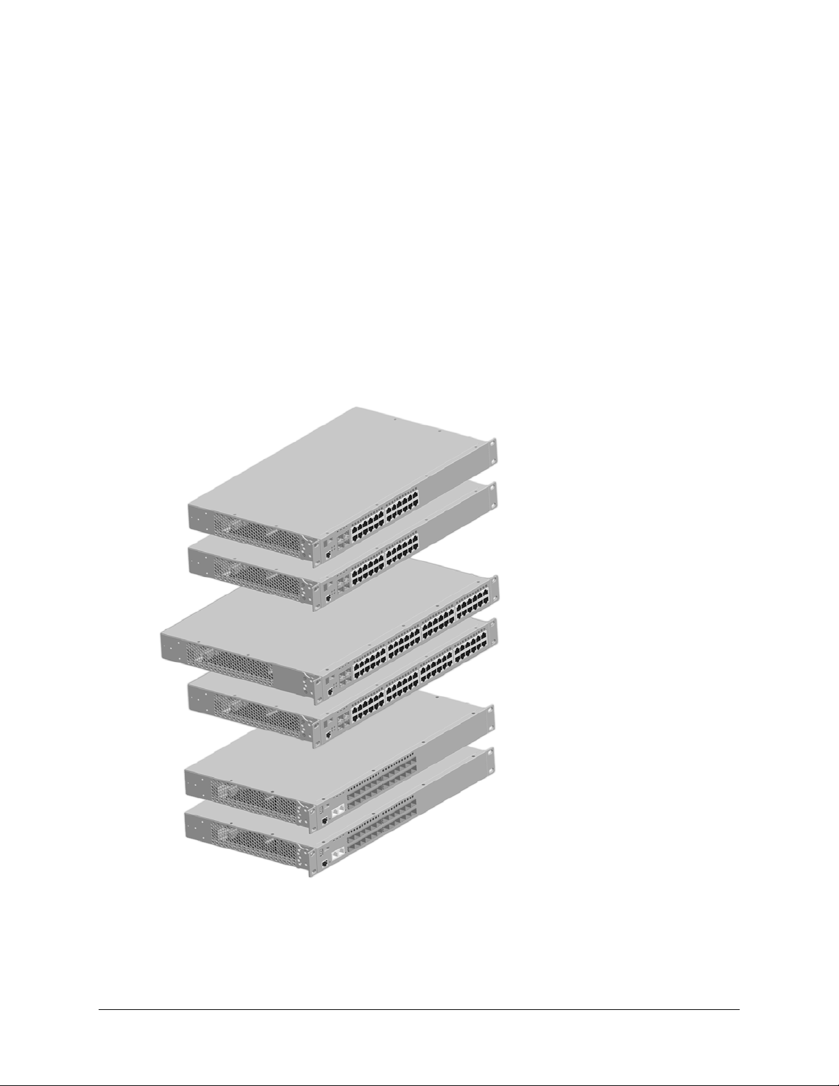
The OmniSwitch 6400 Series (OS6400) is a series of fixed configuration stackable Gigabit Ethernet
switches with advanced Layer 2 and basic routing capabilities. Application examples include the Enterprise edge, the SMB core, as metro access CPE devices, etc.
OS6400 switches are available in 24 port copper and fiber configurations, as well as 48 port copper
configurations. Power over Ethernet (PoE), DC power, Backup Power Supply (BPS) are also offered.
Refer to “OmniSwitch 6400 Series Chassis Configurations” on page 1-2 for additional details.
OmniSwitch 6400-24
OmniSwitch 6400-P24/P24H
OmniSwitch 6400-48
OmniSwitch 6400-P48/P48H
OmniSwitch 6400-U24
OmniSwitch 6400-U24D
OmniSwitch 6400 Series Hardware Users Guide August 2008 page 1-1

OmniSwitch 6400 Series Chassis Configurations OmniSwitch 6400 Series
OmniSwitch 6400 Series Chassis Configurations
OmniSwitch 6400-24
The OmniSwitch 6400-24 (OS6400-24) is a 24-port fixed stackable chassis with 20 RJ-45 ports
configurable to 10/100/1000, four (4) combo SFP/RJ45 ports, and two (2) 10 Gigabit Ethernet
stacking ports.The OS6400-24 contains one internal AC power supply, an external AC or DC Backup
Power Supply (BPS) is also available.
OmniSwitch 6400-48
The OmniSwitch 6400-48 (OS6400-48) is a 48-port fixed stackable chassis with 44 RJ-45 ports
configurable to 10/100/1000, four (4) combo SFP/RJ45 ports, and two (2) 10 Gigabit Ethernet
stacking ports.The OS6400-48 contains one internal AC power supply, an external AC or DC Backup
Power Supply (BPS) is also available.
OmniSwitch 6400-P24
The OmniSwitch 6400-P24 (OS6400-P24) is a 24-port Power over Ethernet (PoE) capable stackable
chassis with 20 RJ-45 ports configurable to 10/100/1000, four (4) combo SFP/RJ45 ports, and two
(2) 10 Gigabit Ethernet stacking ports. The OS6400-P24 supports two external 360W power supplies.
OmniSwitch 6400-P48
The OmniSwitch 6400-P48 (OS6400-P48) is a 48-port Power over Ethernet (PoE) capable stackable
chassis with 44 RJ-45 ports configurable to 10/100/1000, four (4) combo SFP/RJ45 ports, and two
(2) 10 Gigabit Ethernet stacking ports. The OS6400-P48 supports two external 360W power supplies.
OmniSwitch 6400-P24H
The OmniSwitch 6400-P24H (OS6400-P24H) is a 24-port Power over Ethernet (PoE) capable
stackable chassis with 20 RJ-45 ports configurable to 10/100/1000, four (4) combo SFP/RJ45 ports,
and two (2) 10 Gigabit Ethernet stacking ports. The OS6400-P24H supports two external 510W power
supplies.
OmniSwitch 6400-P48H
The OmniSwitch 6400-P48H (OS6400-P48H) is a 48-port Power over Ethernet (PoE) capable
stackable chassis with 44 RJ-45 ports configurable to 10/100/1000, four (4) combo SFP/RJ45 ports,
and two (2) 10 Gigabit Ethernet stacking ports. The OS6400-P48H supports two external 510W power
supplies.
OmniSwitch 6400-U24
The OmniSwitch 6400-U24 (OS6400-U24) is a 24-port AC powered fixed stackable chassis with 22 SFP
fiber ports (100 or 1000BaseX), two (2) combo SFP/RJ45 ports, and two (2) 10 Gigabit Ethernet stacking
ports. The OS6400-U24 contains one internal AC power supply, an external AC or DC Backup Power
Supply (BPS) is also available.
OmniSwitch 6400-U24D
The OmniSwitch 6400-U24D (OS6400-U24D) is a 24-port DC powered fixed stackable chassis with
22 SFP fiber ports (100 or 1000BaseX), two (2) combo SFP/RJ45 ports, and two (2) 10 Gigabit
Ethernet stacking ports. The OS6400-U24D contains one internal DC power supply, an external AC or DC
Backup Power Supply (BPS) is also available.
page 1-2 OmniSwitch 6400 Series Hardware Users Guide August 2008

OmniSwitch 6400 Series Availability Features
Availability Features
The switch provides a broad variety of availability features. Availability features are hardware and
software-based safeguards that help to prevent the loss of data flow in the unlikely event of a subsystem
failure. In addition, some availability features allow users to maintain or replace hardware components
without powering off the switch or interrupting switch operations. Combined, these features provide added
resiliency and help to ensure that the switch or virtual chassis is consistently available for day-to-day
network operations.
Hardware-related availability features include:
• Software Rollback
• Backup Power Supplies
• Hot Swapping
• Hardware Monitoring
Software Rollback
Software rollback (also referred to as image rollback) essentially allows the OmniSwitch 6400 Series
switches to return to a prior “last known good” version of software in the event of a system software problem. The switch controls software rollback through its resilient directory structure design (i.e., /flash/
working and /flash/certified).
For detailed information on the software rollback feature, as well as the switch’s /flash/working and
/flash/certified directories, refer to the “Managing CMM Directory Content” chapter in the OmniSwitch
Switch Management Guide.
Backup Power Supplies
The OmniSwitch 6400 Series switches support an optional backup power supply. This power supply is
connected to the rear of the unit. There is a power shelf provided with the unit that slides into the rear of
the chassis and is used to hold the power supplies. It can hold 510W or 360W power supply or in case of
non-PoE product switches 120W or 126W power supply. This provides redundant chassis power on a 1:1
basis.
Backup power supplies operate in active standby mode. If the primary power supply fails unexpectedly,
the backup power supply automatically takes up the full power load without disrupting the switch.
Note. For more information on backup power supplies, refer to Chapter 2, “OmniSwitch 6400 Series
Chassis and Hardware Components.”
OmniSwitch 6400 Series Hardware Users Guide August 2008 page 1-3

Availability Features OmniSwitch 6400 Series
Hot Swapping
Hot swapping refers to the action of adding, removing, or replacing components without powering off
switches or disrupting other components.This feature facilitates hardware upgrades and maintenance and
allows users to easily replace components in the unlikely event of hardware failure.
The following hardware components can be hot swapped:
• Backup power supply
• Backup power supply connector cables
• SFPs
For instructions on hot swapping backup power supplies, refer to Chapter 3, “Mounting OS6400
Switches.” For instructions on hot swapping combo connector SFPs, refer to the instruction card provided
with the SFP product.
Hardware Monitoring
Automatic Monitoring
Automatic monitoring refers to the switch’s built-in sensors that automatically monitor operations. If an
error is detected (e.g., over-threshold temperature), the switch immediately sends a trap to the user. The
trap is displayed on the console in the form of a text error message. (In the case of an over-threshold
temperature condition, the chassis displays an amber TMP LED in addition to sending a trap.)
LEDs
LEDs, which provide visual status information, are provided on the chassis front panel. LEDs are used to
indicate conditions such as hardware and software status, temperature errors, link integrity, data flow, etc.
For detailed LED descriptions, refer to Chapter 2, “OmniSwitch 6400 Series Chassis and Hardware
Components.”
User-Driven Monitoring
User-driven hardware monitoring refers to CLI commands that are entered by the user in order to access
the current status of hardware components. The user enters “show” commands that output information to
the console. Monitoring information for chassis components, such as the optional back up power supply,
chassis temperature sensor, and chassis fans is provided in Chapter 2, “OmniSwitch 6400 Series Chassis
and Hardware Components.” The show commands for all the features are described in detail in the
OmniSwitch CLI Reference Guide.
page 1-4 OmniSwitch 6400 Series Hardware Users Guide August 2008
2 OmniSwitch 6400 Series
Chassis and Hardware
Components
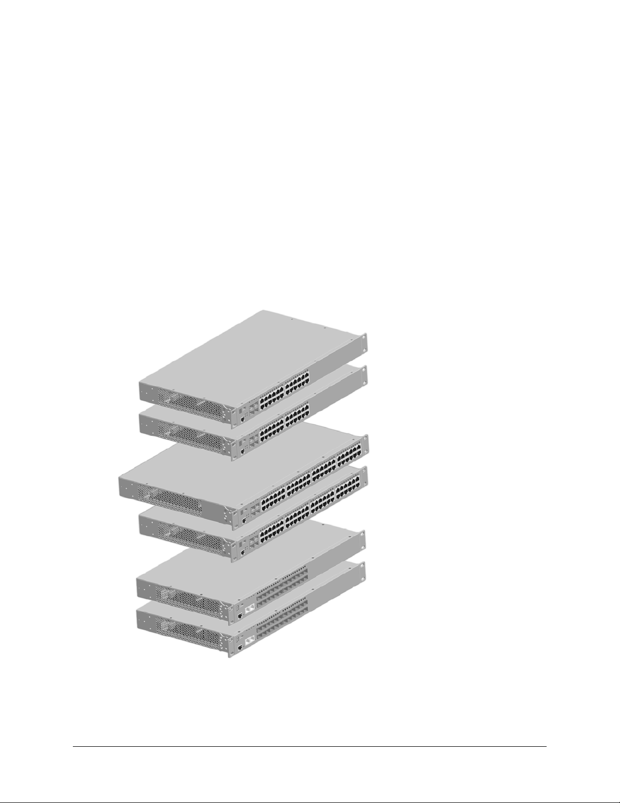
OmniSwitch 6400 Series Chassis Configurations
OmniSwitch 6400-24
OmniSwitch 6400-P24/P24H
OmniSwitch 6400-48
OmniSwitch 6400-P48/P48H
OmniSwitch 6400-U24
OmniSwitch 6400-U24D
OmniSwitch 6400 Series Hardware Users Guide August 2008 page 2-1
OmniSwitch 6400 Series Chassis Configurations OmniSwitch 6400 Series Chassis and Hardware Components
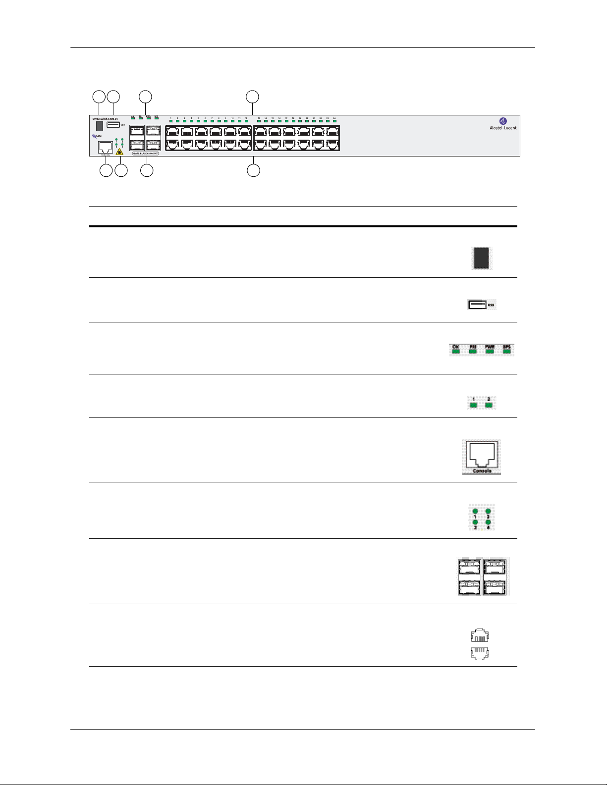
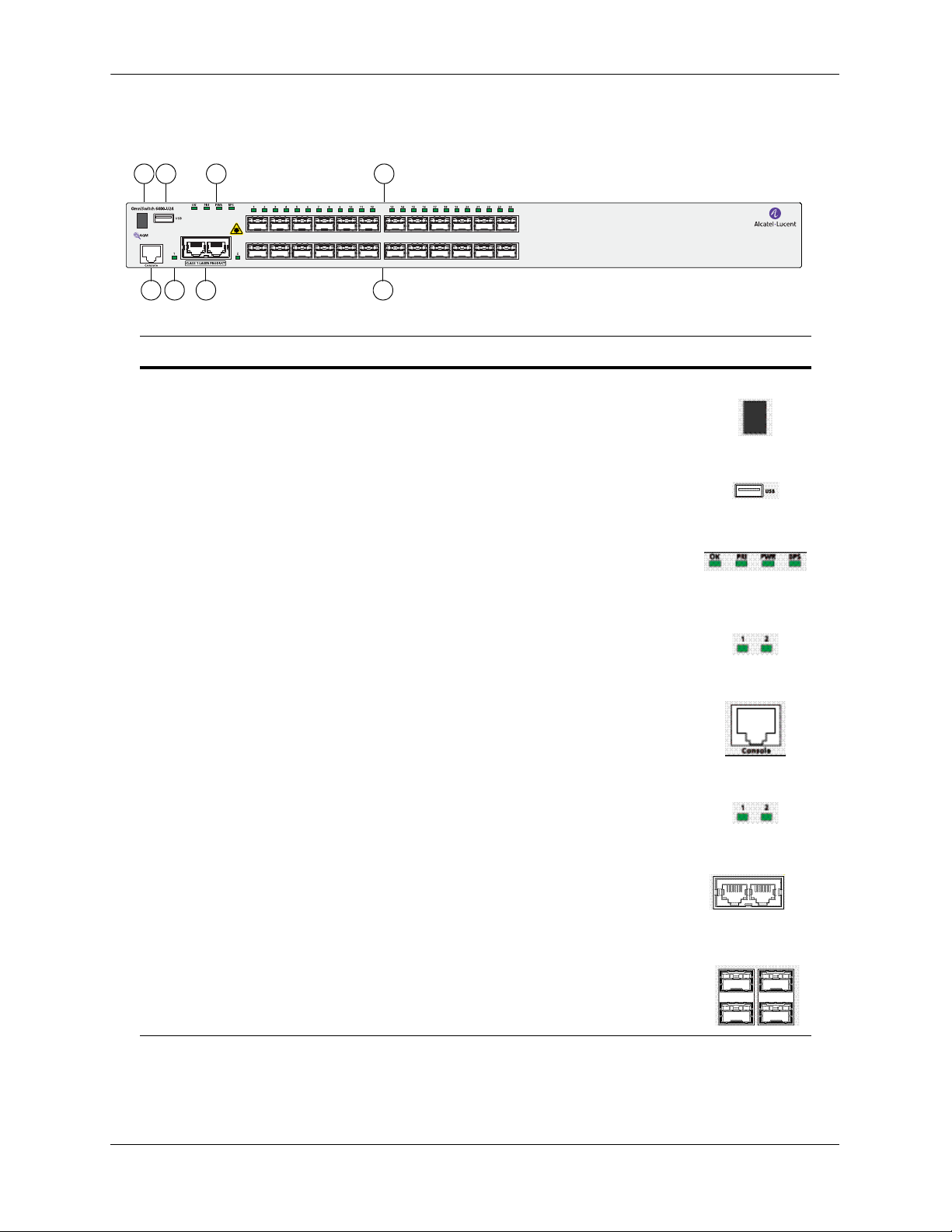
OmniSwitch 6400-24 Front Panel
A B C D
F G HE
OS6400-24 Front Panel
Item Description
A
LED Indicator
Seven segment LED provides stack element ID.
B
USB Port
High speed USB 2.0 port.
C
System Status LEDs
Provides status on hardware, software, primary and redundant power. Refer
to “LED Status Indicators” on page 2-20 for LED status information.
D
10/100/1000BaseT RJ-45 Port LEDs
Provides link and traffic status. Refer to “LED Status Indicators” on
page 2-20 for LED status information.
E
Console Port
RS-232 console port with an RJ-45 connector. Provides access to the CLI for
configuration and management.
F
SFP Combo Port LEDs
Provides link and traffic status for SFP transceivers. Refer to “LED Status
Indicators” on page 2-20 for LED status information.
G
SFP Combo Ports
Four combo (1-4) SFP connectors for various supported SFP transceivers.
Odd-numbered ports are on top row, even-numbered ports are on bottom
row.
H
10/100/1000BaseT RJ-45 Ports
Twenty 10/100/1000BaseT non-combo (5–24) and four 10/100/1000BaseT
combo (1–4) ports. Odd-numbered ports are on top row, even-numbered
ports are on bottom row.
page 2-2 OmniSwitch 6400 Series Hardware Users Guide August 2008

OmniSwitch 6400 Series Chassis and Hardware Components OmniSwitch 6400 Series Chassis Configurations
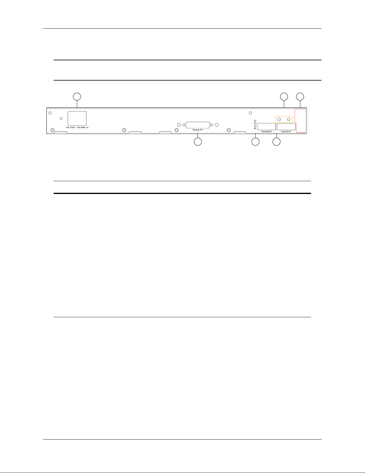
OmniSwitch 6400-24 Rear Panel
Note. The figure shows a pre-production version of the chassis without product, safety, and compliance
information labels. All production versions of the chassis have these labels.
A B C
E FD
OS6400-24 Rear Panel
Item Description
A
Power Supply Connector
Internal 126W AC power supply.
B
Grounding Block
Type LCD8-10A-L grounding lug
C
D
Fan Tray filter
Redundant Power Supply Connector
DB-25 connector for optional external redundant power supply.
E
Stacking/Uplink LEDs
Provides link or traffic status for stacking/uplink connectors. Refer to “LED Status
Indicators” on page 2-20 for LED status information.
F
Stacking/Uplink Connectors
Connectors for use in stacking switches into a virtual chassis or as an uplink port.
OmniSwitch 6400 Series Hardware Users Guide August 2008 page 2-3

OmniSwitch 6400 Series Chassis Configurations OmniSwitch 6400 Series Chassis and Hardware Components
OS6400-24 Specifications
Total non-combo 10/100/
1000Base-T ports per switch (5–24)
Total combo 10/100/1000Base-T
combo ports per switch (1–4)
Total combo SFP connectors per
switch (1–4)
Total 10/100/1000Base-T ports per
stack
Total SFP connectors per stack 32 (stack of eight switches)
Power Primary (Internal): 126W AC
Flash memory size 128 MB
RAM memory size 256 MB SDRAM
Width 17.32 in. (44.0 cm)
Height 1.73 in. (4.4 cm)
Height (rack units) 1 RU
Depth 17.75 in. (45.09 cm) (with external power supply)
Weight 9.43 lbs.(4.28 kg)
20
4
4
192 (stack of eight switches)
Redundant (External): 126W AC or 120W DC
10.75 in. (27.31 cm) (without external power supply)
Relative Humidity Operating: 5% to 95% (non-condensing)
Storage: 5% to 95% (non-condensing)
Ambient Temperature Operating: 32º F to 113º F (0 ºC to 45 ºC)
Storage: 14º F to 158º F (-10 ºC to 70 ºC)
Altitude Operating: Up to 10,000 ft. (3048 m)
Storage: Up to 40,000 ft. (12192 m)
Maximum frame size 9216 bytes
Ethernet standards 802.3i (10BaseT), Cable: (Cat 5 UTP)
802.3u (100BaseTX), Cable: (Cat 5e/6 UTP, EIA/TIA 568)
802.3ab (1000Base-T), Cable: (Cat -5e/6, UTP, EIA/TIA 568)
802.3z (1000Base-X), Cable: (SMF, MMF)
802.3ah (EFM), Cable: (SMF, MMF)
802.3ae (10GBase-X) Cable: (SMF,MMF)
Maximum cable distance (RJ-45) 100 meters
page 2-4 OmniSwitch 6400 Series Hardware Users Guide August 2008
OmniSwitch 6400 Series Chassis and Hardware Components OmniSwitch 6400 Series Chassis Configurations
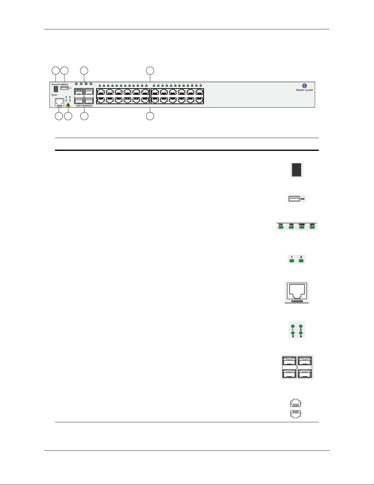
OmniSwitch 6400-P24 Front Panel
A B C D
G HE
F
OS6400-P24 Front Panel
Item Description
A
LED Indicator
Seven segment LED provides stack element ID.
B
USB Port
High speed USB 2.0 port.
C
System Status LEDs
Provides status on hardware, software, primary and redundant power. Refer
to “LED Status Indicators” on page 2-20 for LED status information.
D
10/100/1000BaseT RJ-45 Power Over Ethernet Port LEDs
Provides link and traffic status. Refer to “LED Status Indicators” on
page 2-20 for LED status information.
E
Console Port
RS-232 console port with an RJ-45 connector. Provides access to the CLI for
configuration and management.
F
SFP Combo Port LEDs
Provides link and traffic status for SFP transceivers. Refer to “LED Status
Indicators” on page 2-20 for LED status information.
G
SFP Combo Ports
Four combo (1-4) SFP connectors for various supported SFP transceivers.
Odd-numbered ports are on top row, even-numbered ports are on bottom
row.
H
10/100/1000BaseT RJ-45 Power Over Ethernet Ports
Twenty 10/100/1000BaseT non-combo (5–24) and four 10/100/1000BaseT
combo (1–4) PoE ports. Odd-numbered ports are on top row, even-numbered
ports are on bottom row.
OmniSwitch 6400 Series Hardware Users Guide August 2008 page 2-5

OmniSwitch 6400 Series Chassis Configurations OmniSwitch 6400 Series Chassis and Hardware Components
OmniSwitch 6400-P24 Rear Panel
Note. The figure shows a pre-production version of the chassis without product, safety, and compliance
information labels. All production versions of the chassis have these labels.
B
Item Description
A
Primary PS1 Power Supply Connector
DB-25 connector for required external primary power supply.
B
Redundant PS2 Power Supply Connector
DB-25 connector for optional external redundant power supply.
C
Grounding Block
Type LCD8-10A-L grounding lug
D
Stacking/Uplink LEDs
Provides link or traffic status for stacking/uplink connectors. Refer to “LED Status
Indicators” on page 2-20 for LED status information.
A
OS6400-P24 Rear Panel
C
B
D
E
E
Stacking/Uplink Connectors
Connectors for use in stacking switches into a virtual chassis or as an uplink port
Note . The rear panel of the OS6400-P24 contains three DB-25 power supply connectors for connecting
external 360W and 510W power supplies. One of the connectors is labeled 'Primary PS1' and two of the
connectors are labeled 'Backup PS2'. The primary power supply must be connected to the 'Primary PS1'
connector. A redundant power supply can be connected to either of the 'Backup PS2' connectors.
page 2-6 OmniSwitch 6400 Series Hardware Users Guide August 2008

OmniSwitch 6400 Series Chassis and Hardware Components OmniSwitch 6400 Series Chassis Configurations
OS6400-P24 Specifications
Total non-combo
10/100/1000 Base-T PoE ports per
switch (5–24)
Total combo 10/100/1000 Base-T
PoE ports per switch (1–4)
Total combo SFP connectors per
switch (1–4)
Total 10/100/1000 Base-T PoE per
stack
Total combo SFP connectors per
stack
Power Primary (External): 360W AC or 510W AC
Flash memory size 128 MB
RAM memory size 256 MB SDRAM
Width 17.32 in. (44.0 cm)
Height 1.73 in. (4.4 cm)
Height (rack units) 1 RU
Depth 17.75 in. (45.09 cm) (with external power supply)
20
4
4
192 (stack of eight switches)
32 (stack of eight switches)
Redundant (External): 360W AC or 510W AC
10.75 in. (27.31 cm) (without external power supply)
Weight 8.97 lbs. (4.07 kg)
Relative Humidity Operating: 5% to 95% (non-condensing)
Storage: 5% to 95% (non-condensing)
Ambient Temperature Operating: 32º F to 113º F (0 ºC to 45 ºC)
Storage: 14º F to 158º F (-10 ºC to 70 ºC)
Altitude Operating: Up to 10,000 ft. (3048 m)
Storage: Up to 40,000 ft. (12192 m)
Maximum frame size 9216 bytes
Ethernet standards 802.3i (10BaseT), Cable: (Cat 5 UTP)
802.3u (100BaseTX), Cable: (Cat 5e/6 UTP, EIA/TIA 568)
802.3ab (1000Base-T), Cable: (Cat -5e/6, UTP, EIA/TIA 568)
802.3z (1000Base-X), Cable: (SMF, MMF)
802.3ah (EFM), Cable: (SMF, MMF)
802.3ae (10GBase-X) Cable: (SMF,MMF)
Maximum cable distance (RJ-45) 100 meters
OmniSwitch 6400 Series Hardware Users Guide August 2008 page 2-7
OmniSwitch 6400 Series Chassis Configurations OmniSwitch 6400 Series Chassis and Hardware Components
OmniSwitch 6400-U24 Front Panel
A B C D
F G HE
OS6400-U24 Front Panel
Item Description
A
LED Indicator
Seven segment LED provides stack element ID.
B
USB Port
High speed USB 2.0 port.
C
System Status LEDs
Provides status on hardware, software, primary and redundant power. Refer
to “LED Status Indicators” on page 2-20 for LED status information.
D
SFP LEDs
Provides link and traffic status. Refer to “LED Status Indicators” on
page 2-20 for LED status information.
E
Console Port
RS-232 console port with an RJ-45 connector. Provides access to the CLI for
configuration and management.
F
10/100/1000BaseT RJ-45 Combo Port LEDs
Provides link and traffic status. Refer to “LED Status Indicators” on
page 2-20 for LED status information.
G
10/100/1000BaseT RJ-45 Combo Ports
Two 10/100/1000BaseT RJ-45 combo ports (1–2).
H
SFP Connectors
Twenty-two non-combo SFP connectors (3-24) and two combo SFP connectors (1-2) for various supported SFP transceivers. Odd-numbered ports are
on top row, even-numbered ports are on bottom row.
page 2-8 OmniSwitch 6400 Series Hardware Users Guide August 2008
OmniSwitch 6400 Series Chassis and Hardware Components OmniSwitch 6400 Series Chassis Configurations
OmniSwitch 6400-U24 Rear Panel
Note. The figure shows a pre-production version of the chassis without product, safety, and compliance
information labels. All production versions of the chassis have these labels.
A B C
E FD
OS6400-U24 Rear Panel
Item Description
A
Power Supply Connector
Internal 126W AC power supply.
B
Grounding Block
Type LCD8-10A-L grounding lug
C
D
Fan Tray filter
Redundant Power Supply Connector
DB-25 connector for optional external redundant power supply.
E
Stacking/Uplink LEDs
Provides link or traffic status for stacking/uplink connectors. Refer to “LED Status
Indicators” on page 2-20 for LED status information.
F
Stacking/Uplink Connectors
Connectors for use in stacking switches into a virtual chassis or as an uplink port.
OmniSwitch 6400 Series Hardware Users Guide August 2008 page 2-9

OmniSwitch 6400 Series Chassis Configurations OmniSwitch 6400 Series Chassis and Hardware Components
OS6400-U24 Specifications
Total non-combo SFP connectors
per switch (3–24)
Total combo SFP connectors per
switch (1–2)
Total combo 10/100/1000
Base-T ports per switch (1–2)
Total SFP connectors per stack 192 (stack of eight switches)
Total 10/100/1000 Base-T ports
per stack
Power Primary (Internal): 126W AC
Flash memory size 128 MB
RAM memory size 256 MB SDRAM
Width 17.32 in. (44.0 cm)
Height 1.73 in. (4.4 cm)
Height (rack units) 1 RU
Depth 17.75 in. (45.09 cm) (with external power supply)
Weight 9.76 lbs. (4.43 kg)
22
2
2
16 (stack of eight switches)
Redundant (External): 126W AC or 120W DC
10.75 in. (27.31 cm) (without external power supply)
Relative Humidity Operating: 5% to 95% (non-condensing)
Storage: 5% to 95% (non-condensing)
Ambient Temperature Operating: 32º F to 113º F (0 ºC to 45 ºC)
Storage: 14º F to 158º F (-10 ºC to 70 ºC)
Altitude Operating: Up to 10,000 ft. (3048 m)
Storage: Up to 40,000 ft. (12192 m)
Maximum frame size 9216 bytes
Ethernet standards 802.3i (10BaseT), Cable: (Cat 5 UTP)
802.3u (100BaseTX), Cable: (Cat 5e/6 UTP, EIA/TIA 568)
802.3ab (1000Base-T), Cable: (Cat -5e/6, UTP, EIA/TIA 568)
802.3z (1000Base-X), Cable: (SMF, MMF)
802.3ah (EFM), Cable: (SMF, MMF)
802.3ae (10GBase-X) Cable: (SMF,MMF)
Maximum cable distance (RJ-45) 100 meters
page 2-10 OmniSwitch 6400 Series Hardware Users Guide August 2008

OmniSwitch 6400 Series Chassis and Hardware Components OmniSwitch 6400 Series Chassis Configurations
OmniSwitch 6400-U24D Front Panel
A B C D
F G HE
OS6400-U24D Front Panel
Item Description
A
LED Indicator
Seven segment LED provides stack element ID.
B
USB Port
High speed USB 2.0 port.
C
System Status LEDs
Provides status on hardware, software, primary and redundant power. Refer
to “LED Status Indicators” on page 2-20 for LED status information.
D
SFP LEDs
Provides link and traffic status. Refer to “LED Status Indicators” on
page 2-20 for LED status information.
E
Console Port
RS-232 console port with an RJ-45 connector. Provides access to the CLI for
configuration and management.
F
10/100/1000BaseT RJ-45 Combo Port LEDs
Provides link and traffic status. Refer to “LED Status Indicators” on
page 2-20 for LED status information.
G
10/100/1000BaseT RJ-45 Combo Ports
Two 10/100/1000BaseT RJ-45 combo ports (1–2).
H
SFP Connectors
Twenty-two non-combo SFP connectors (3-24) and and two combo SFP
connectors (1-2) for various supported SFP transceivers. Odd-numbered
ports are on top row, even-numbered ports are on bottom row.
OmniSwitch 6400 Series Hardware Users Guide August 2008 page 2-11

OmniSwitch 6400 Series Chassis Configurations OmniSwitch 6400 Series Chassis and Hardware Components
OmniSwitch 6400-U24D Rear Panel
Note. The figure shows a pre-production version of the chassis without product, safety, and compliance
information labels. All production versions of the chassis have these labels.
A B C
E FD
OS6400-U24D Rear Panel
Item Description
A
Power Supply Connector
Internal 120W DC power supply.
B
Grounding Block
Type LCD8-10A-L grounding lug
C
D
Fan Tray filter
Redundant Power Supply Connector
DB-25 connector for optional external redundant power supply.
E
Stacking/Uplink LEDs
Provides link or traffic status for stacking/uplink connectors. Refer to “LED Status
Indicators” on page 2-20 for LED status information.
F
Stacking/Uplink Connectors
Connectors for use in stacking switches into a virtual chassis or as an uplink port.
page 2-12 OmniSwitch 6400 Series Hardware Users Guide August 2008

OmniSwitch 6400 Series Chassis and Hardware Components OmniSwitch 6400 Series Chassis Configurations
OmniSwitch 6400-U24D Front Panel
OS6400-U24D Specifications
Total non-combo SFP connectors
per switch (3–24)
Total combo SFP connectors per
switch (1–2)
Total combo 10/100/1000Base-T
ports per switch (1–2)
Total SFP connectors per stack 192 (stack of eight switches)
Total 10/100/1000Base-T ports
per stack
Power Primary (Internal): 120W DC
Flash memory size 128 MB
RAM memory size 256 MB SDRAM
Width 17.32 in. (44.0 cm)
Height 1.73 in. (4.4 cm)
Height (rack units) 1 RU
Depth 17.75 in. (45.09 cm) (with external power supply)
Weight 9.23 lbs. (4.19 kg)
22
2
2
16 (stack of eight switches)
Redundant (External): 120W DC or 126W AC
10.75 in. (27.31 cm) (without external power supply)
Relative Humidity Operating: 5% to 95% (non-condensing)
Storage: 5% to 95% (non-condensing)
Ambient Temperature Operating: 32º F to 113º F (0 ºC to 45 ºC)
Storage: 14º F to 158º F (-10 ºC to 70 ºC)
Altitude Operating: Up to 10,000 ft. (3048 m)
Storage: Up to 40,000 ft. (12192 m)
Maximum frame size 9216 bytes
Ethernet standards 802.3i (10BaseT), Cable: (Cat 5 UTP)
802.3u (100BaseTX), Cable: (Cat 5e/6 UTP, EIA/TIA 568)
802.3ab (1000Base-T), Cable: (Cat -5e/6, UTP, EIA/TIA 568)
802.3z (1000Base-X), Cable: (SMF, MMF)
802.3ah (EFM), Cable: (SMF, MMF)
802.3ae (10GBase-X) Cable: (SMF,MMF)
Maximum cable distance (RJ-45) 100 meters
OmniSwitch 6400 Series Hardware Users Guide August 2008 page 2-13

OmniSwitch 6400 Series Chassis Configurations OmniSwitch 6400 Series Chassis and Hardware Components
OmniSwitch 6400-48
A B C D
F G HE
OS6400-48 Front Panel
Item Description
A
LED Indicator
Seven segment LED provides stack element ID.
B
USB Port
High speed USB 2.0 port.
C
System Status LEDs
Provides status on hardware, software, primary and redundant power. Refer
to “LED Status Indicators” on page 2-20 for LED status information.
D
10/100/1000BaseT RJ-45 Port LEDs
Provides link and traffic status. Refer to “LED Status Indicators” on
page 2-20 for LED status information.
E
Console Port
RS-232 console port with an RJ-45 connector. Provides access to the CLI for
configuration and management.
F
SFP Combo Port LEDs
Provides link and traffic status. Refer to “LED Status Indicators” on
page 2-20 for LED status information.
G
SFP Combo Ports
Four combo (1-4) SFP connectors for various supported SFP transceivers.
Odd-numbered ports are on top row, even-numbered ports are on bottom
row.
H
10/100/1000BaseT RJ-45 Ports
Forty-four 10/100/1000 BaseT non-combo (5–48) and four 10/100/1000
BaseT combo (1–4) ports. Odd-numbered ports are on top row, even-numbered ports are on bottom row.
page 2-14 OmniSwitch 6400 Series Hardware Users Guide August 2008

OmniSwitch 6400 Series Chassis and Hardware Components OmniSwitch 6400 Series Chassis Configurations
OmniSwitch 6400-48 Rear Panel
Note. The figure shows a pre-production version of the chassis without product, safety, and compliance
information labels. All production versions of the chassis have these labels.
A B C
E FD
OS6400-48 Rear Panel
Item Description
A
Power Supply Connector
Internal 126W AC power supply.
B
Grounding Block
Type LCD8-10A-L grounding lug
C
D
Fan Tray filter
Redundant PS2 Power Supply Connector
DB-25 connector for optional external redundant power supply.
E
Stacking/Uplink LEDs
Provides link or traffic status for stacking/uplink connectors. Refer to “LED Status
Indicators” on page 2-20 for LED status information.
F
Stacking/Uplink Connectors
Connectors for use in stacking switches into a virtual chassis or as an uplink port.
OmniSwitch 6400 Series Hardware Users Guide August 2008 page 2-15

OmniSwitch 6400 Series Chassis Configurations OmniSwitch 6400 Series Chassis and Hardware Components
OS6400-48 Specifications
Total non-combo 10/100/1000
Base-T ports per switch (5–48)
Total combo 10/100/1000Base-T
combo ports per switch (1–4)
Total combo SFP connectors per
switch (1–4)
Total 10/100/1000 Base-T ports
per stack
Total SFP connectors per stack 32 (stack of eight switches)
Power Primary (Internal): 126W AC
Flash memory size 128 MB
RAM memory size 256 MB SDRAM
Width 17.32 in. (44.0 cm)
Height 1.73 in. (4.4 cm)
Height (rack units) 1 RU
Depth 20.25 in. (51.43 cm) (with external power supply)
Weight 11.97 lbs. (5.43 kg)
44
4
4
384 (stack of eight switches)
Redundant (External): 126W AC or 120W DC
13.25 in. (33.67 cm) (without external power supply)
Relative Humidity Operating: 5% to 95% (non-condensing)
Storage: 5% to 95% (non-condensing)
Ambient Temperature Operating: 32º F to 113º F (0 ºC to 45 ºC)
Storage: 14º F to 158º F (-10 ºC to 70 ºC)
Altitude Operating: Up to 10,000 ft. (3048 m)
Storage: Up to 40,000 ft. (12192 m)
Maximum frame size 9216 bytes
Ethernet standards 802.3i (10BaseT), Cable: (Cat 5 UTP)
802.3u (100BaseTX), Cable: (Cat 5e/6 UTP, EIA/TIA 568)
802.3ab (1000Base-T), Cable: (Cat -5e/6, UTP, EIA/TIA 568)
802.3z (1000Base-X), Cable: (SMF, MMF)
802.3ah (EFM), Cable: (SMF, MMF)
802.3ae (10GBase-X) Cable: (SMF,MMF)
Maximum cable distance (RJ-45) 100 meters
page 2-16 OmniSwitch 6400 Series Hardware Users Guide August 2008

OmniSwitch 6400 Series Chassis and Hardware Components OmniSwitch 6400 Series Chassis Configurations
OmniSwitch 6400-P48 Front Panel
A B C D
F G HE
OS6400-P48 Front Panel
Item Description
A
LED Indicator
Seven segment LED provides stack element ID.
B
USB Port
High speed USB 2.0 port.
C
System Status LEDs
Provides status on hardware, software, primary and redundant power. Refer
to “LED Status Indicators” on page 2-20 for LED status information.
D
10/100/1000BaseT RJ-45 PoE Ports
Forty-four 10/100/1000 BaseT non-combo (5–48) and four 10/100/1000
BaseT combo (1–4) PoE ports. Odd-numbered ports are on top row, evennumbered ports are on bottom row.
E
Console Port
RS-232 console port with an RJ-45 connector. Provides access to the CLI for
configuration and management.
F
SFP Combo Port LEDs
Provides link and traffic status. Refer to “LED Status Indicators” on
page 2-20 for LED status information.
G
SFP Combo Ports
Four combo (1-4) SFP connectors for various supported SFP transceivers.
Odd-numbered ports are on top row, even-numbered ports are on bottom
row.
H
10/100/1000BaseT Ethernet LEDs
Provides link and traffic status. Refer to “LED Status Indicators” on
page 2-20 for LED status information.
OmniSwitch 6400 Series Hardware Users Guide August 2008 page 2-17

OmniSwitch 6400 Series Chassis Configurations OmniSwitch 6400 Series Chassis and Hardware Components
OmniSwitch 6400-P48 Rear Panel
Note. The figure shows a pre-production version of the chassis without product, safety, and compliance
information labels. All production versions of the chassis have these labels.
B
Item Description
A
Primary PS1 Power Supply Connector
DB-25 connector for required external primary power supply.
B
Redundant PS2 Power Supply Connector
DB-25 connector for optional external redundant power supply.
C
Grounding Block
Type LCD8-10A-L grounding lug
D
Stacking/Uplink LEDs
Provides link or traffic status for stacking/uplink connectors. Refer to “LED Status
Indicators” on page 2-20 for LED status information.
A
OS6400-P48 Rear Panel
B C
D
E
E
Stacking/Uplink Connectors
Connectors for use in stacking switches into a virtual chassis or as an uplink port
Note . The rear panel of the OS6400-P48 contains three DB-25 power supply connectors for connecting
external 360W and 510W power supplies. One of the connectors is labeled 'Primary PS1' and two of the
connectors are labeled 'Backup PS2'. The primary power supply must be connected to the 'Primary PS1'
connector. A redundant power supply can be connected to either of the 'Backup PS2' connectors.
page 2-18 OmniSwitch 6400 Series Hardware Users Guide August 2008

OmniSwitch 6400 Series Chassis and Hardware Components OmniSwitch 6400 Series Chassis Configurations
OS6400-P48 Specifications
Total non-combo 10/100/
1000Base-T PoE ports per switch
(5–48)
Total combo 10/100/1000 Base-T
PoE combo ports per switch (1–4)
Total combo SFP connectors per
switch (1–4)
Total 10/100/1000 Base-T PoE
ports per stack
Total combo SFP connectors per
stack
Power Primary (External): 360W AC or 510W AC
Flash memory size 128 MB
RAM memory size 256 MB SDRAM
Width 17.32 in. (44.0 cm)
Height 1.73 in. (4.4 cm)
Height (rack units) 1 RU
Depth 17.75 in. (45.09 cm) (with external power supply)
44
4
4
384 (stack of eight switches)
32 (stack of eight switches)
Redundant (External): 360W AC or 510W AC
10.75 in. (27.31 cm) (without external power supply)
Weight 9.92 lbs. (4.50 kg)
Relative Humidity Operating: 5% to 95% (non-condensing)
Storage: 5% to 95% (non-condensing)
Ambient Temperature Operating: 32º F to 113º F (0 ºC to 45 ºC)
Storage: 14º F to 158º F (-10 ºC to 70 ºC)
Altitude Operating: Up to 10,000 ft. (3048 m)
Storage: Up to 40,000 ft. (12192 m)
Maximum frame size 9216 bytes
Ethernet standards 802.3i (10BaseT), Cable: (Cat 5 UTP)
802.3u (100BaseTX), Cable: (Cat 5e/6 UTP, EIA/TIA 568)
802.3ab (1000Base-T), Cable: (Cat -5e/6, UTP, EIA/TIA 568)
802.3z (1000Base-X), Cable: (SMF, MMF)
802.3ah (EFM), Cable: (SMF, MMF)
802.3ae (10GBase-X) Cable: (SMF,MMF)
Maximum cable distance (RJ-45) 100 meters
OmniSwitch 6400 Series Hardware Users Guide August 2008 page 2-19

LED Status Indicators OmniSwitch 6400 Series Chassis and Hardware Components
LED Status Indicators
LED State Description
OK Solid Green
Solid Amber
Blinking Green
PRI Solid Green
Solid Amber
Off
PWR Solid Green
Solid Amber
Off
BPS Solid Green
Solid Amber
Off
10/100/1000 Solid Green
Blinking Green
System software is operational.
Hardware or System failure.
Normal Diagnostics.
Primary unit in a stack or standalone
switch.
Secondary unit in a stack.
Switch is idle. (not primary or
secondary)
Primary power supply operational.
Primary power supply failure.
Primary power supply not present.
Redundant power supply operational.
Redundant power supply failure.
Redundant power supply not present.
Valid Link.
Transmitting or receiving packets in
a link up state for non-PoE .
Solid Amber
Blinking Amber
Off
SFP Solid Green
Blinking Green
Off
X1/X2 Currently Not Supported. N/A
Valid PoE Link.
Transmitting or receiving packets in
a link up state for PoE .
No link.
Valid Link.
Transmitting or receiving packets .
No link.
page 2-20 OmniSwitch 6400 Series Hardware Users Guide August 2008

OmniSwitch 6400 Series Chassis and Hardware Components OmniSwitch 6400 Series Power Supplies
OmniSwitch 6400 Series Power Supplies
OmniSwitch 6400 Series switches support the following power supplies:
• PS-510W-AC Power Supply (see “PS-510W-AC Power Supply” on page 2-22)
• PS-360W-AC Power Supply (see “PS-360W-AC Power Supply” on page 2-23)
• PS-126W-AC Power Supply (see “PS-126W-AC Power Supply” on page 2-24)
• PS-120W-DC Power Supply (see “PS-120W-DC Power Supply” on page 2-25)
• 126W AC Internal Power Supply (see “126W AC Internal Power Supply” on page 2-26)
• 120W DC Internal Power Supply (see “120W DC Internal Power Supply” on page 2-26)
OmniSwitch 6400 Series Hardware Users Guide August 2008 page 2-21

OmniSwitch 6400 Series Power Supplies OmniSwitch 6400 Series Chassis and Hardware Components
PS-510W-AC Power Supply
The PS-510W-AC Power Supply provides system and PoE power and can be installed as either a primary
or redundant power supply.
510W AC System/PoE Power Supply
P/S Component Description
Model PS-510W-AC
Provides Primary and Redundant
System and PoE For
Input Voltage Range 100 to 240 VAC
Rated Frequency 50 to 60 Hz
Maximum PoE Output Power 400 W
Maximum System Output Power 130 W
PoE Output Voltage -50.0 VDC
PoE Output Current 8.2 A (maximum)
Sytem Output Voltage 12.0 VDC (typical)
Sytem Output Current 10.0 A (maximum)
Width 12.25 in. (31.12 cm)
Height 1.73 in. (4.4 cm) (1 RU)
Depth 6.25 in. (15.86 cm)
Weight 5.71 lbs. (2.59 kg)
OS6400-P24 and OS6400-P48
page 2-22 OmniSwitch 6400 Series Hardware Users Guide August 2008

OmniSwitch 6400 Series Chassis and Hardware Components OmniSwitch 6400 Series Power Supplies
PS-360W-AC Power Supply
The PS-360W-AC Power Supply provides system and PoE and can be installed as either a primary or
redundant power supply.
360W AC System/PoE Power Supply
P/S Component Description
Model PS-360W-AC
Provides Primary and Redundant
System and PoE For
Input Voltage Range 100 to 240 VAC
Rated Frequency 50 to 60 Hz
Maximum PoE Output Power 230 W
Maximum System Output Power 130 W
PoE Output Voltage -50.0 VDC
PoE Output Current 4.6 A (maximum)
Sytem Output Voltage 12.0 VDC (typical)
Sytem Output Current 10.8 A (maximum)
Width 6.25 in. (15.86 cm)
Height 1.73 in. (4.4 cm) (1 RU)
Depth 6.25 in. (15.86 cm)
Weight 3.22 lbs. (1.46 kg)
OS6400-P24 and OS6400-P48
OmniSwitch 6400 Series Hardware Users Guide August 2008 page 2-23

OmniSwitch 6400 Series Power Supplies OmniSwitch 6400 Series Chassis and Hardware Components
PS-126W-AC Power Supply
The PS-126W-AC Power Supply provides system power and can be installed as a redundant system power
supply.
126W AC System Power Supply
P/S Component Description
Model PS-126W-AC
Provides Redundant System
Power For
Input Voltage Range 90 to 264 VAC
Rated Frequency 50 to 60 Hz
Maximum Output Power 126 W
Output Voltage 12.0 VDC (typical)
Output Current 10.5 A (maximum)
Width 6.25 in. (15.86 cm)
Height 1.73 in. (4.4 cm) (1 RU)
Depth 6.25 in. (15.86 cm)
Weight 2.45 lbs. (1.11 kg)
OS6400-24, OS6400-48, OS6400-U24, OS6400-U24D
page 2-24 OmniSwitch 6400 Series Hardware Users Guide August 2008

OmniSwitch 6400 Series Chassis and Hardware Components OmniSwitch 6400 Series Power Supplies
PS-120W-DC Power Supply
The PS-120W-DC Power Supply provides full system power and can be installed as a redundant system
power supply.
120W -48VDC System Power Supply
P/S Component Description
Model PS-120W-DC
Provides Redundant System
Power For
Input Voltage Range 36 to 72 VDC (24V Nominal Input)
Input Current 3.3A @ 48VDC
Maximum Output Power 120 W
Output Voltage 12.0 VDC (typical)
Output Current 10.0 A (maximum)
Width 6.25 in. (15.86 cm)
Height 1.73 in. (4.4 cm) (1 RU)
Depth 6.25 in. (15.86 cm)
Weight 2.09 lbs. (.95 kg)
OS6400-24, OS6400-48, OS6400-U24, OS6400-U24D
OmniSwitch 6400 Series Hardware Users Guide August 2008 page 2-25

OmniSwitch 6400 Series Power Supplies OmniSwitch 6400 Series Chassis and Hardware Components
126W AC Internal Power Supply
The 126W Internal Power Supply provides full system power.
P/S Component Description
Model 126W AC Internal Power Supply
Provides Primary System Power
For
Input Voltage Range 100 to 240 VAC
Rated Frequency 47 to 63 Hz
Maximum Output Power 126 W
Output Voltage 12.0 VDC (typical)
Output Current 10.8 A (maximum)
OS6400-24, OS6400-48, OS6400-U24
126W AC Internal System Power Supply
120W DC Internal Power Supply
The 120W DC Internal Power Supply provides full system power.
P/S Component Description
Model 120W DC Internal Power Supply
Provides Primary System Power
For
Input Voltage Range 36 to 72 VDC (24V Nominal Input)
Input Current 3.3A @ 48VDC
Maximum Output Power 120 W
Output Voltage 12.0 VDC (typical)
Output Current 10.0 A (maximum)
120W -48VDC Internal System Power Supply
OS6400-U24D
page 2-26 OmniSwitch 6400 Series Hardware Users Guide August 2008

OmniSwitch 6400 Series Chassis and Hardware Components OmniSwitch 6400 Series Power Supplies
Power Supply Shelf
Alcatel-Lucent requires the use of the power supply shelf when connecting power supplies. The shelf can
be attached directly to the back of the chassis or rack mounted.
OS6400 Power Supply Shelf
OmniSwitch 6400 Series Hardware Users Guide August 2008 page 2-27

AC Power Cords OmniSwitch 6400 Series Chassis and Hardware Components
AC Power Cords
Since the power cord is the switch’s only disconnect device, it should be plugged into an easily accessible
outlet. In the event that your power cord is lost or damaged, refer to the specifications below.
Specifications
The power cord included with this product contains three (3) insulated #18AWG stranded copper wires
and is rated between 85-265 VAC (region dependent), 10 amps with a nominal length of 2 meters. The
female end terminates in an IEC-60320-C15 attachment plug and the male end termination varies dependent upon region, as listed below.
European cords must be Harmonized (HAR) type. Refer to the information below for power plug types by
region:
Power Cord Types User Side Connectors
North America NEMA 5-15-P
United Kingdom / Ireland BS 1363 UK
Europe CEE 7/7
Japan JIS 8303
Australia AS 3112
India BS 546
Italy CIE 23-16
Switzerland / Liechtenstein SEV 1011
Denmark / Greenland SRAF 1962 / DB 16/87
Argentina A-10
Supplied OS6400 Power Cord Specifications
IEC-60320-C15
page 2-28 OmniSwitch 6400 Series Hardware Users Guide August 2008

OmniSwitch 6400 Series Chassis and Hardware Components DC Power Specifications
DC Power Specifications
In addition to the installation steps described in “Connecting a Power Supply to the Chassis” on page 3-12
and “Rack Mounting Power Supplies” on page 3-14 DC power supplies have the following additional
considerations:
• Connect to a -48V reliably grounded DC SELV source.
• Use common DC return connections for the DC power supplies. The DC return terminal conductor
should be connected to the equipment frame.
• The Branch Circuit Overcurrent Protection must be rated a Maximum of 15A.
• Use 12AWG solid conductors only.
• A readily accessible disconnect device that is suitably approved and rated shall be incorporated in the
field wiring.
Black
MIN 1 TURN PER 1.5
Red
HALF TURN PER .75
Twisted pair wire (red and black) for a DC power supply
OmniSwitch 6400 Series Hardware Users Guide August 2008 page 2-29

Console Port OmniSwitch 6400 Series Chassis and Hardware Components
Console Port
The console port, located on the chassis front panel, provides a console connection to the switch and is
required when logging into the switch for the first time. By default, this RJ-45 connector provides an RS232 DTE console connection.
Serial Connection Default Settings
The factory default settings for the serial connection are as follows:
baud rate 9600
parity none
data bits (word size) 8
stop bits 1
flow control none
Modifying the Serial Connection Settings
The switch’s serial connection defaults are listed above. If you wish to modify the default serial connection settings (i.e., baud rate, parity, data bits, and stop bits), refer to the following steps:
Note. You must be connected to the switch via the console port before attempting to change serial connection settings. Otherwise, an error message will display.
For switches in a stacked configuration, all changes must be configured before the switches are cabled
together. In other words, you must configure these settings when each switch is operating as a stand-alone
unit.
1 Enter the modify boot parameters command at the CLI prompt. The boot prompt displays:
Boot >
2 To change the baud rate, enter boot serialbaudrate, followed by the desired baud rate value. Options
include 1200, 2400, 4800, 9600 (default), 19200, 38400, 57600, 76800, and 115200. For example:
Boot > boot serialbaudrate 19200
Note. Setting the console port to speeds above 9600 baud can cause problems with Zmodem uploads.
3 To change the parity value, enter boot serialparity, followed by the desired parity value. Options
include none (default), even, and odd. For example:
Boot > boot serialparity even
4 To change the data bits (i.e., word size) value, enter boot serialwordsize, followed by the number of
data bits. Options include 7 and 8 (default). For example:
Boot > boot serialwordsize 7
page 2-30 OmniSwitch 6400 Series Hardware Users Guide August 2008

OmniSwitch 6400 Series Chassis and Hardware Components Console Port
5 To change the stop bits value, enter boot serialstopbits, followed by the number of stop bits. Options
include 1 (default) and 2. For example:
Boot > boot serialstopbits 2
6 Verify your current changes by entering show at the boot prompt:
Boot > show
Edit buffer contents:
Serial (console) baud : 19200
Serial (console) parity : even
Serial (console) stopbits : 2
Serial (console) wordsize : 7
(additional table output not shown)
7 You can save your changes to the boot.params file by entering commit file at the boot prompt:
Boot > commit file
When the commit file command is used, changes will not be enabled until after the next switch reboot.
8 You can also save your changes in real time to the switch’s running memory by entering commit
system at the boot prompt:
Boot > commit system
Note. There are two important things to consider when using the commit system command to save serial
connection changes:
• Output to the terminal may become illegible due to incompatible serial connection settings between the
switch and the terminal emulation software.
• If you use the commit system command only, changes will not be saved to the switch’s boot.params
file and will be lost if the switch is rebooted. To save changes to the boot.params file, refer to step 7.
9 Return to the CLI prompt by entering exit at the boot prompt.
OmniSwitch 6400 Series Hardware Users Guide August 2008 page 2-31

Console Port OmniSwitch 6400 Series Chassis and Hardware Components
Port Pinouts
10/100 Ethernet Port – RJ-45 Pinout (non-PoE)
Pin Number Description
1RX+
2RX3TX+
4 not used
5 not used
6TX7 not used
8 not used
Gigabit Ethernet Port – RJ-45 Pinout
Pin Number Description
1BI_DB+
2BI_DB3BI_DA+
4BI_DD+
5BI_DD6BI_DA7BI_DC+
8BI_DC-
10/100/1000 Mbps Power over Ethernet Port – RJ-45 Pinout
Pin Number Description
1 RX+ (-VDC)
2 RX- (-VDC)
3TX+ (+VDC)
4
5
6 TX- (+VDC)
7
8
page 2-32 OmniSwitch 6400 Series Hardware Users Guide August 2008

OmniSwitch 6400 Series Chassis and Hardware Components Console Port
RJ-45 Console Port – Connector Pinout
Pin Number Signals as DTE Console Port
1NC
2NC
3RXD
4Ground
5Ground
6TXD
7NC
8NC
OmniSwitch 6400 Series Hardware Users Guide August 2008 page 2-33

Console Port OmniSwitch 6400 Series Chassis and Hardware Components
page 2-34 OmniSwitch 6400 Series Hardware Users Guide August 2008

3 Mounting OS6400
Switches
Note. Never obstruct the air intake or exhaust vents located on the chassis. Obstructing these vents can
cause switch failure. Always follow the recommended clearance values.
General Mounting Recommendations
Be sure that your switch is placed in a well-ventilated, static-free environment. Always allow adequate
clearance at the front, rear, top, and sides of the switch. Refer the table below for detailed information on
recommended chassis clearances.
Recommended Clearances
The following table shows the recommended minimum clearances for adequate chassis airflow and access
to cabling and components at the front and rear of the chassis.
Location
Top No minimum clearance required. However, be sure that the top of the chassis is not in
direct contact with any equipment above.
Bottom No minimum clearance required. However, be sure that the bottom of the chassis is not in
direct contact with any equipment below.
Sides 2 inches
Rear 6 inches (see note below)
Front 6 inches (see note below)
Note. Clearance recommendations at the front and rear of chassis are for access to cabling and
components only and are not intended as a specific airflow requirement. If a redundant power supply is to
be attached directly to the rear of the switch chassis (see page 3-12), additional clearance will be required
to accommodate the power supply tray.
OmniSwitch 6400 Series Hardware Users Guide August 2008 page 3-1

General Mounting Recommendations Mounting OS6400 Switches
Elevated Operating Ambient Temperatures
If installed in a closed or multi-unit rack assembly, the operating ambient temperature of the rack environment may be greater than room ambient. Therefore, consideration should be given to installing the equipment in an environment compatible with the maximum ambient temperature (Tma) specified by the
manufacturer.
Reduced Air Flow
Installation of the equipment in a rack should be such that the amount of air flow required for safe
operation of the equipment is not compromised.
Mechanical Loading
Mounting of the equipment in the rack should be such that a hazardous condition is not achieved due to
uneven mechanical loading.
Circuit Overloading
Consideration should be given to the connection of the equipment to the supply circuit and the effect that
overloading of the circuit might have on overcurrent protection and supply wiring. Appropriate consideration of equipment nameplate ratings should be used when addressing this concern.
Reliable Earthing
Note. Reliable earthing of rack-mount equipment should be maintained. Particular attention should be
given to supply connections other than direct connections to the branch circuit (e.g. use of power strips). If
you are relocating the switch, be sure to power it down and remove all network, stacking, and power
cables before moving.
page 3-2 OmniSwitch 6400 Series Hardware Users Guide August 2008

Mounting OS6400 Switches Airflow Recommendations
Airflow Recommendations
The OmniSwitch 6400 draws air from intake vents located in the left chassis panel and exhausts air via fan
vents located in the right chassis panel.
For each switch, air is directed horizontally through the chassis, where it passes over the circuit board and
provides necessary cooling for internal components. Refer to the diagram below for more information.
1. Air Intake. The chassis fans pull air
from the main air intake vents located in
the left-hand panel of the chassis.
Front of Chassis
Rear of Chassis
3. Air Exhaust. The airflow
is exhausted through the fan
exhaust vents at the righthand side of the chassis.
2. Airflow. The air from the intake
vent is directed through the chassis
past the circuit board. This airflow
provides required cooling for
chassis components.
OmniSwitch 6400 Series Hardware Users Guide August 2008 page 3-3

Installation Overview Mounting OS6400 Switches
Installation Overview
OmniSwitch 6400 Series switches can be installed in various configurations. Refer to the guidelines below
before mounting the chassis and power supplies.
Note. OmniSwitch 6400 Series switches must be placed “right side up.” Never attempt to operate a switch
positioned on its side.
Mounting Guidelines
• Installation of a power supply shelf and external power supply is required for PoE-ready OmniSwitch
6400 Series models (OS6400-P24 and OS6400-P48). All other models have an internal power supply
and external power supplies are only needed if power redundancy is required.
• Be sure that adequate clearance has been provided for chassis airflow and access to the front, back, and
sides of the switch. For recommended clearances, refer to page 3-1.
• Be sure that you have placed the chassis within reach of all the required AC or DC power sources.
• If you are placing multiple switches in a stacked configuration Be sure to maintain adequate clearance
at the front, rear, left, and right side of all switches (see page 3-1). Up to eight switches may be stacked
to form a single virtual chassis. Also, be sure that you have placed all switches in the stack within reach
of required power sources and necessary cables once the switches are stacked together. See “Cabling
Stacked Configurations” on page 3-9.
Mounting Options
The OmniSwitch 6400 Series switches can be installed in the following ways:
• Tabletop installation with no external power supply (for OS6400-24 and OS6400-48 switches with no
power redundancy requirements)
• Tabletop installation with power supply directly attached to chassis (for OS6400-P24 and OS6400-P48
models or any OS6400 chassis with power redundancy)
• Rack-mount installation with no external power supply (for OS6400-24 and OS6400-48 switches with
no power redundancy requirements)
• Rack-mount installation with power supply directly attached to rear of the chassis (for OS6400-P24
and OS6400-P48 models or any OS6400 chassis with power redundancy)
• Rack-mount installation with power supply rack-mounted and connected with cable (for OS6400-P24
and OS6400-P48 models or any OS6400 chassis with power redundancy)
Important Note. If an external power supply is to be used (PoE or redundant power configurations), be
sure to install the power supply shelf and all external power supplies before table or rack-mounting the
chassis. Instructions for installing the power supply shelf and external power supplies are provided on
page 3-12.
page 3-4 OmniSwitch 6400 Series Hardware Users Guide August 2008

Mounting OS6400 Switches Tabletop Installation
Tabletop Installation
OmniSwitch 6400 Series switches can be installed as a tabletop unit.
Note. Be sure that adequate clearance has been provided for chassis airflow and access to the front, back,
and sides of the switch. For recommended clearances, refer to “Recommended Clearances” on page 3-1.
Also, be sure that you have placed the chassis within the reach of all the required AC power sources.
To install the switch as a tabletop unit, follow the steps below:
1 If no external power supply is required for this installation, skip to step 2.
If a PoE-ready switch (OS6400-P24 and OS6400-P48) or non-PoE switch with redundant system power is
being installed, begin this installation by securing an external power supply shelf and power supply to the
back of the chassis as described on page 3-12. After completing the power supply shelf and external power
supply installation, return to this section to complete the steps below.
2 Remove the factory installed attachment screws and mounting brackets from the left and right sides of
the switch chassis and set them aside.
3 Table mounted switches can be screwed directly to the table using a table mount flange kit (available
from Alcatel-Lucent). (The table mount flanges also provide rubber feet to protect the table surface.) If
this kit is to used, orient the table mounting brackets so that the rubber bumper faces down and attach the
brackets to both the left and right side of the switch using the attachment screws removed at step (refer to
illustration below).
Note. The optional table mount flange kit is not mandatory. If the switch does not need to be firmly
secured to the table surface, simply place the switch on the table surface.
OmniSwitch 6400 Series Hardware Users Guide August 2008 page 3-5

Tabletop Installation Mounting OS6400 Switches
4 If the table mount flange kit is being used, install the table mount brackets to the rear portion of the
chassis.
5 Mount the switch assembly on the table by inserting attachment screws through the flat portion of the
mounting brackets and into the mounting surface.
Next Steps
Powering On the Switch
To power on the chassis refer to “Connecting Chassis to Power Source” on page 3-18.
Stacking Multiple Switches Into a Virtual Chassis
To stack multiple switches into a virtual chassis, refer to “Setting Up a Stacked Configuration” on
page 3-9.
page 3-6 OmniSwitch 6400 Series Hardware Users Guide August 2008

Mounting OS6400 Switches Rack-Mount Installation
Rack-Mount Installation
Rack Mount Guidelines
Refer to the important guidelines below before installing the OmniSwitch 6400 Series chassis on a rack.
• It is recommended that two people install the switch on the rack—one person to hold the chassis and
position it on the rack, and a second person to secure the chassis to the rack using attachment screws
(not supplied).
• Alcatel-Lucent provides two rack-mount flanges with each OmniSwitch 6400 Series switch. These
flanges support standard 19-inch rack-mount installations. These flanges must be attached to the chassis before the switch can be rack mounted.
Note. If you are installing the switch in a 23-inch-wide rack, Alcatel-Lucent offers optional 23-inch rackmounting hardware. For more information, contact your Alcatel-Lucent representative.
• Alcatel-Lucent does not provide rack-mount screws. Use the screws supplied by the rack vendor.
• To prevent a rack from becoming top heavy, it is recommended that you install heavier equipment at
the bottom of the rack, whenever possible.
• If you are installing the switch on a relay rack, be sure to install and secure the rack per the rack manu-
facturer’s specifications.
• Review page 3-1 for important chassis airflow and access recommendations before installing.
Rack Mounting Steps
1 If no external power supply is required for this installation, skip to step 2.
External power supplies can be installed directly to the rear of the chassis or in the rack directly above or
below the switch. If an external power supply is being mounted to the rear of the chassis, begin this installation by following the steps beginning on page 3-12. After completing the power supply shelf and external power supply installation, return to this section and complete the steps below.
Rack Mounting Power Supplies. Detailed information on rack mounting power supplies is provided on
page 3-7.
2 Mark the holes on the rack where the switch is to be installed.
3 Lift and position the switch until the factory installed rack mount flanges are flush with the rack post.
4 Align the holes in the flanges with the rack holes that were marked in step 2.
OmniSwitch 6400 Series Hardware Users Guide August 2008 page 3-7

Rack-Mount Installation Mounting OS6400 Switches
5 Once the holes are aligned, insert a rack mount screw (not provided) through the bottom hole of each
flange. Tighten both screws until they are secure.
Attaching the Switch to the Rack
Note. Be sure to install the screws in the bottom hole of each flange, as shown, before proceeding.
6 Once the screws at the bottom of each flange are secure, install the remaining rack mount screw. Be
sure that all screws are securely tightened.
Next Steps
Rack Mounting Power Supplies
Detailed information on rack mounting power supplies is provided on page 3-7.
Powering On the Switch
To power on the chassis refer to “Connecting Chassis to Power Source” on page 3-18.
Stacking Multiple Switches Into a Virtual On the Switch
To stack multiple switches into a virtual chassis, refer to “Setting Up a Stacked Configuration” on
page 3-9.
page 3-8 OmniSwitch 6400 Series Hardware Users Guide August 2008

Mounting OS6400 Switches Setting Up a Stacked Configuration
Setting Up a Stacked Configuration
Rack Mounting Stacked Configurations
Prior to setting up and cabling the stacked configuration, be sure that all switches are in place and installed
according to the instructions beginning on page 3-5 (table mount configuration) or 3-7 (rack mount
configuration). Up to eight switches may be stacked to form a single virtual chassis.
Note. When rack mounting multiple switches in a stacked configuration, be sure to position all switches in
the rack so that all required stacking cables will have adequate length for the installation.
Cabling Stacked Configurations
In order to connect stacked switches into a virtual chassis, all modules in the stack must be connected via
stacking cables.
Redundant Stacking Cable Connections
In addition to the stacking cables installed between adjacent switch, the top-most switch and bottom-most
switch in the stack must be connected using a redundant stacking cable.
Recommended Cabling Patterns
Switches in a stack are connected to each other by stacking cables. The valid cable lengths are 1.5m
(4.9 feet), 60cm (23.6 inches), and 30cm (11.8 inches). These stacking cables provide high-speed, dualredundant links between switches in a stack.
For a stack to have effective redundancy, a redundant stacking cable must be installed between the upper-
most and bottom-most switch at all times. This provides effective failover in the event of a stacking link or
module failure within the stack.
The diagram below shows the recommended stacking cable pattern.
A B
A stack of eight switches in a crossed (stacking port
A to stacking port B) configuration. Note that a
redundant stacking cable connection exists between
the top and bottom switches. This connection is
required for effective redundancy across the stack.
Recommended Stacking Cable Patterns (Chassis Rear Panels Shown)
OmniSwitch 6400 Series Hardware Users Guide August 2008 page 3-9

Setting Up a Stacked Configuration Mounting OS6400 Switches
Cabling Steps
1 Before inserting a stacking cable into one of the stacking, be sure to orient the stacking cable connec-
tor properly. The wide portion of the connector must be facing up. Refer to the diagram below for more
information.
Connector Top
2 Starting from the top of the stack, insert one end of the stacking cable into either stacking port A or
stacking port B. The stacking port (A or B) depends on your preferred cabling pattern. Be sure that cable
connector is completely inserted and fully seated in the chassis.
3 Insert the other end of the stacking cable into the stacking port of the switch immediately below. Once
again, the stacking port (A or B) depends on the preferred cabling pattern.
4 Repeat this procedure until all switches in the stack are connected (see illustrations a, b, and c below).
Reminder. The diagram below shows one supported stacking cable pattern. For additional supported
cabling patterns, refer to Chapter 6, “Managing OmniSwitch 6400 Series Stacks.”
When orienting the stacking cable connector, be sure
that the wider portion of the connector is facing up as
shown. Otherwise, the stacking cable will not fit
properly in the chassis’ stacking port.
End View of Stacking Cable Connector
a
page 3-10 OmniSwitch 6400 Series Hardware Users Guide August 2008
b
Connecting the Switches in the Stack
c

Mounting OS6400 Switches Setting Up a Stacked Configuration
5 To provide added resiliency and redundancy, you must install the redundant stacking cable to connect
the top switch in the stack to the bottom switch. Connect the redundant cable now. Refer to the diagram
below for more information:
Redundant Connection Between Top and Bottom Switches
6 Once all stacking cable connectors are inserted, tighten the captive screws at the left- and right-hand
sides of each connector as shown. Be sure not to overtighten the screws.
Tightening Stacking Connector Captive Screws
7 Now that all switches in the stack are connected, continue to “Connecting Chassis to Power Source” on
page 3-18.
OmniSwitch 6400 Series Hardware Users Guide August 2008 page 3-11

Installing Power Supplies Mounting OS6400 Switches
Installing Power Supplies
OmniSwitch 6400 Series power supply can be installed in the following ways:
• As a primary or backup supply directly connected to the back of an OmniSwitch 6400 Series chassis.
See “Connecting a Power Supply to the Chassis” below for more information.
• As a primary or backup supply rack mounted directly above or below the switch and connected with a
cable. See “Connecting Chassis to Power Source” on page 3-18 for more information.
DC power supplies require additional installation steps. See “DC Power Specifications” on page 2-29 for
more information.
Anti-Static Warning. Before handling any components, free yourself of static by wearing a grounding
strap, or by grounding yourself properly. Static discharge can damage the switch and the backup power
supply.
Connecting a Power Supply to the Chassis
Follow the steps below to connect a power supply directly (i.e., without a cable) to the rear of an
OmniSwitch 6400 Series chassis.
Note. For information on rack mounting power supplies and connecting the power supply via a connector
cable, refer to “Rack Mounting Power Supplies” on page 3-14.
1 Place the chassis, power supply, and shelf on a smooth, clean, and dry surface.
2 Carefully slide the power shelf so that it is flush against the back of the chassis.
3 Tighten the two captive screws located on the left and right sides of the power shelf.
page 3-12 OmniSwitch 6400 Series Hardware Users Guide August 2008

Mounting OS6400 Switches Connecting a Power Supply to the Chassis
4 Carefully slide the power supply against the back of the chassis until the power connectors securely
connect.
5 Verify that the captive screw for the power supply is aligned with the threaded hole in the power
supply shelf. Secure the power supply to the power supply shelf by tightening the captive screw.
6 Repeat the steps above for any additional required power supplies.
Next Steps
Mounting the Switch
For information on table mounting the switch and power supply tray, refer to “Tabletop Installation” on
page 3-5. For information on rack mounting the switch and power supply tray, refer to “Rack-Mount
Installation” on page 3-7.
Powering On the Switch
To power on the chassis refer to “Connecting Chassis to Power Source” on page 3-18.
Stacking Multiple Switches Into a Virtual On the Switch
To stack multiple switches into a virtual chassis, refer to “Setting Up a Stacked Configuration” on
page 3-9.
OmniSwitch 6400 Series Hardware Users Guide August 2008 page 3-13

Rack Mounting Power Supplies Mounting OS6400 Switches
Rack Mounting Power Supplies
The following sections describe how to rack-mount a power supply shelf and connect the power supply
with a cable.
Note. For information on connecting a power supply directly to the rear of the chassis (without a connector cable), refer to “Connecting a Power Supply to the Chassis” on page 3-12.
Power Supply Shelf Rack Mounting Steps
Follow the steps below to rack-mount the power supply shelf:
1 Align the threaded holes in the provided rack-mount flanges with the two holes in the power supply
shelf. These holes are located on the left and right sides of the shelf.
2 Attach the flanges to the chassis using the provided Phillips-head screws. The screws slide through the
non-threaded holes from the inside of the power supply shelf and are then attached to the mounting brackets using the threaded holes. Be sure to tighten each of the screws firmly using a Phillips screwdriver.
Attaching a Rack-Mount Flange
3 Carefully slide the power supply on to the power shelf and secure the power supply to the shelf using
the captive screws.
Tighten these screws
to secure the power
supply.
Attaching a Power Supply to the Power Shelf
page 3-14 OmniSwitch 6400 Series Hardware Users Guide August 2008

Mounting OS6400 Switches Rack Mounting Power Supplies
Note. A single 510W power supply or up to two of any other power supply types can be attached to a
power supply shelf.
4 After the rack-mount flanges and the power supply are secured to the shelf, mark the holes on the rack
where the shelf is to be installed.
5 Lift and position the shelf until the rack-mount flanges are flush with the rack post.
6 Align the holes in the flanges with the rack holes that were marked earlier.
7 Once the holes are aligned, insert a rack mount screw (not provided) through the bottom hole of each
flange. Tighten both screws until they are secure.
Attaching the Power Shelf to the Rack
Note. Be sure to install the screws in the bottom hole of each flange, as shown, before proceeding.
8 Once the screws at the bottom of each flange are secure, install the remaining two rack mount screws.
Be sure that all screws are securely tightened.
Connecting the Power Supply Cable to the Chassis
Follow the steps below to connect a power supply with a cable:
1 Be sure the switch and power shelf are securely fastened to the rack.
2 Connect the proper end of the supplied power supply cable to the appropriately labeled primary or
backup connector on the switch and tighten securely.
3 Connect the other end of the power supply cable to the power supply and securely tighten.
4 Connect the power cord to the power supply.
OmniSwitch 6400 Series Hardware Users Guide August 2008 page 3-15

Rack Mounting Power Supplies Mounting OS6400 Switches
Note. The diagrams below show examples of mounting the switch and power supplies in both a 2U and
3U scenario. Depending on the switch model, power supplies, and rack mounting options the actual
mounting options will vary.
13.5 inches
Redundant 120W-DC, 126W-AC, 360W-PoE
13.5 inches
Redundant 510W-PoE
page 3-16 OmniSwitch 6400 Series Hardware Users Guide August 2008

Mounting OS6400 Switches Rack Mounting Power Supplies
You can also attach the power supplies to the back of an OmniSwitch 6400 Series chassis directly as well
as using cables at the same time, as shown in the diagram below.
17.6 inches
Redundant 510W-PoE
Next Steps
Powering On the Switch
To power on the chassis refer to “Connecting Chassis to Power Source” on page 3-18.
Stacking Multiple Switches Into a Virtual On the Switch
To stack multiple switches into a virtual chassis, refer to “Setting Up a Stacked Configuration” on
page 3-9.
OmniSwitch 6400 Series Hardware Users Guide August 2008 page 3-17

Connecting Chassis to Power Source Mounting OS6400 Switches
Connecting Chassis to Power Source
AC Power Supply Connections
Since the power cord is the switch’s only disconnect device, it should be plugged into an easily accessible
outlet. In the event that your power cord is lost or damaged, refer to the specifications below.
Powering On a Chassis
Follow the steps below to power on the chassis using and AC power source:
1 Connect the IEC-60320-C15 end of the supplied power cord to the primary and optional redundant
power supply.
2 Connect the country specific ends of the supplied power cord to the AC power source.
3 Monitor the chassis as it boots.
page 3-18 OmniSwitch 6400 Series Hardware Users Guide August 2008

Mounting OS6400 Switches Connecting Chassis to Power Source
DC Power Supply Connections
In addition to the installation steps described in “Connecting a Power Supply to the Chassis” on page 3-12
and “Rack Mounting Power Supplies” on page 3-14 DC power supplies have the following additional
considerations:
• Connect to a -48V reliably grounded DC SELV source.
• Use common DC return connections for the DC power supplies. The DC return terminal conductor
should be connected to the equipment frame.
• The Branch Circuit Overcurrent Protection must be rated a Maximum of 15A.
• Use 12AWG solid conductors only.
• A readily accessible disconnect device that is suitably approved and rated shall be incorporated in the
field wiring.
Black
MIN 1 TURN PER 1.5
HALF TURN PER .75
Red
Twisted pair wire (red and black) for a DC power supply
Note. Refer to the wiring diagram for information on connecting the DC power supply to a DC power
source.
Connecting to a DC Power Source
The DC power supply on your switch contains a power connector with three (3) square slots for connecting the positive, negative, and ground wires from a DC power source.
DC Power Connectors
+ -
Side Screws for Connector Removal
OmniSwitch DC Power Supply Connector
OmniSwitch 6400 Series Hardware Users Guide August 2008 page 3-19

Connecting Chassis to Power Source Mounting OS6400 Switches
A clamp inside each slot keeps the power wire tightly in place during operation.
The DC power supply has side screws that can be used to remove the connector if required.
Installing DC Power Source Wire Leads
These instructions describe how to connect your 3-wire DC power source to the power connector on your
DC power supply. A small flat-tip screwdriver and a wire stripper are required for this procedure.
1 Prepare the three (3) wires—12 gauge—that will plug into the power supply. First make sure they are
not plugged into the DC power source. Next, use a wire stripper to carefully strip about a half-inch off the
end of each wire, removing the outer insulation to expose the copper core.
2 Open the clamp for the ground wire slot by inserting a small flat-tip screwdriver into the top of the
appropriate circular hole. Loosen the screw so that the clamp for the ground wire opens.
Loosen Screw.
+ -
Clamp inside square hole will open
when screw is loosened in top circular hole.
Opening Connector for Ground Wire
3 Insert the ground wire lead into the slot. The lead you insert must match the lead attached to the DC
power source.
Warning. You must plug DC wire leads into the correct holes in the DC power connector. Use the labels
above the DC power connector as a guide to positive, negative, and ground connections. If the wire leads
are plugged into the wrong holes, the power supply will not work properly and damage to the unit may
result.
Push the wire in far enough such that it reaches the back wall of the connector, about a half inch
inside.
+ -
Ground Wire
Attaching the Ground Wire
page 3-20 OmniSwitch 6400 Series Hardware Users Guide August 2008

Mounting OS6400 Switches Connecting Chassis to Power Source
4 Tighten the clamp by tightening the screw above the slot into which you inserted the wire lead. The
wire lead should be securely attached inside the connector. You should be able to pull on the wire and not
dislodge it.
Warning. The positive (+) wire of the sourcing equipment, such as a battery or rectifier, must be
connected to the positive (+) terminal of the OmniSwitch DC power supply and the negative (-) wire of
the sourcing equipment must be connected to the negative (-) terminal of the OmniSwitch DC power
supply.
5 Repeat Steps 2 through 4 for the remaining positive and negative wire leads.
OS6400 Power Supply
DC Power Source
Correct Polarity Connections
OmniSwitch 6400 Series Hardware Users Guide August 2008 page 3-21

Hot-Swapping Power Supplies Mounting OS6400 Switches
Hot-Swapping Power Supplies
OmniSwitch 6400 Series switches support hot-swapping of their power supplies. The following sections
describe how to hot-swap a power supply either directly connected (i.e., without a cable) or rack-mounted
power supply.
Warning: Before proceeding, ensure a redundant power supply is connected and operational.
Anti-Static Warning. Before handling any components, free yourself of static by wearing a grounding
strap, or by grounding yourself properly. Static discharge can damage the switch and the backup power
supply.
Hot-Swapping a Power Supply Connected to the Rear of the Chassis
1 Disconnect the power supply to be hot-swapped from its power source.
2 Loosen the captive screw of the power supply to be hot-swapped.
3 Carefully slide the power supply out of the power supply shelf and set aside.
Directly Connected Power Supply
4 Carefully slide the new power supply onto the shelf and against the back of the chassis until the power
connector securely connects
5 Tighten the captive screw for the new power supply to the power supply shelf.
6 Re-connect the power supply to its power source.
page 3-22 OmniSwitch 6400 Series Hardware Users Guide August 2008

Mounting OS6400 Switches Hot-Swapping Power Supplies
Hot-Swapping a Rack Mounted Power Supply
1 Disconnect the power supply to be hot-swapped from its power source.
2 Loosen the power supply cable of the power-supply to be hot-swapped and disconnect from power
supply.
3 Loosen the captive screw of the power supply to be hot-swapped.
4 Carefully slide the power supply out of the power supply shelf and set aside.
Rack-Mounted Power Supplies
5 Carefully slide the new power supply on to the power supply shelf and secure the power supply to the
shelf using the captive screw.
6 Reconnect the power supply cable of the new power-supply and tighten securely.
7 Re-connect the power supply to its power source.
OmniSwitch 6400 Series Hardware Users Guide August 2008 page 3-23

Hot-Swapping Power Supplies Mounting OS6400 Switches
page 3-24 OmniSwitch 6400 Series Hardware Users Guide August 2008

4 Booting OmniSwitch 6400
Series Switches
For information on booting stand-alone switches and switches in stacked configurations, refer to the
sections below.
Booting a Stand-Alone Switch
The OmniSwitch 6400 Series switch does not use an on/off switch. The power cord is the switch’s only
connect/disconnect device. The power connector socket is located on the switch’s rear panel. For more
information, refer to “OmniSwitch 6400 Series Chassis and Hardware Components” on page 2-1.
To boot the switch, plug the power cord (provided) into the power connector socket at the switch’s rear
panel. Next, plug the power cord into an easily-accessible power source, such as a grounded AC outlet or
an Uninterruptible Power Supply (UPS).
The switch immediately begins the boot process. Allow a few moments for the switch to boot completely,
then verify the status of all LEDs on the switch’s front panel. A successful boot for a stand-alone switch
displays the following LED states:
LED States for a Stand-Alone Switch
OK Solid green
PRI Solid green
PWR Solid green
BPS Solid green: Operational
Solid amber: Failed
Off: Not present
Slot Indicator 1–8: depending on the slot number value in the boot.slot.cfg file. The
default value is 1.
If any of the LED state differs from the states shown in the table above, refer to page 2-20 for more information. Contact Alcatel-Lucent Customer Support if the LED state persists.
For information on logging in and configuring your OmniSwitch 6400 Series switch, refer to the
OmniSwitch 6400 Series Getting Started Guide and OmniSwitch AOS Release 6 Switch Management
Guide.
OmniSwitch 6400 Series Hardware Users Guide August 2008 page 4-1

Booting Stacked Configurations Booting OmniSwitch 6400 Series Switches
Booting Stacked Configurations
Once the switches have been connected to a virtual chassis, the next step is to manually power on the
stack. The OmniSwitch 6400 Series switch does not use an on/off switch. The power cord is the switch’s
only connect/disconnect device. The power connector socket is located on the switch’s rear panel. For
more information, refer to “OmniSwitch 6400 Series Chassis and Hardware Components” on page 2-1.
To boot the stack, plug the power cord (provided) into the power connector socket at the rear panel of each
switch in the stack. Next, plug all power cords, in rapid succession, into easily-accessible power sources,
such as grounded AC outlets or an Uninterruptible Power Supply (UPS).
Note. Be sure to power on all switches in the stack in rapid succession; otherwise, switches may be
assigned unintended stack management roles. Refer to Chapter 6, “Managing OmniSwitch 6400 Series
Stacks.” for detailed information.
The stack immediately begins the boot process. Allow a few moments for all elements in the stack to boot
completely, then verify the status of all LEDs on the switch’s front panel. A successful boot for a stacked
OmniSwitch displays the following LED states.
LED States for a Stacked Configuration
OK Solid green for all switches.
PRI Solid green: Primary management module
Solid amber: Secondary management module
Off: Idle (Neither primary or secondary)
Detailed information for primary, secondary, and idle roles is provided
in Chapter 6, “Managing OmniSwitch 6400 Series Stacks.”
PWR Solid green for all switches.
BPS Solid green: Operational
Solid amber: Failed
Off: Not present
Slot Indicator 1–8: Depending on the slot number assignment for each switch. See
Chapter 6, “Managing OmniSwitch 6400 Series Stacks.” for detailed
information.
If any of the LED state differs from the states shown in the table above, refer to page 2-20 for more information. Contact Alcatel-Lucent Customer Support if the LED state persists.
page 4-2 OmniSwitch 6400 Series Hardware Users Guide August 2008

Booting OmniSwitch 6400 Series Switches Monitoring the Chassis
Monitoring the Chassis
OmniSwitch 6400 Series switches can be monitored and managed via the console port using Command
Line Interface (CLI) commands. The switches can also be monitored and managed remotely using CLI
commands, WebView, SNMP, and OmniVista.
The section below provides some examples of useful hardware-related monitoring CLI commands. Refer
to the OmniSwitch CLI Reference Guide for detailed information on all management and monitoring
commands used with the OmniSwitch 6400 Series switch.
Checking the Overall Chassis Status
To check the overall status of a chassis, including the chassis type, and current administrative and operational status, use the show chassis command. For example:
-> show chassis
Chassis 1
Model Name: OS6400-48,
Description: 10/100/1000,
Part Number: 902274-10,
Hardware Revision: 005,
Serial Number: 439L0024,
Manufacture Date: FEP 22 2008,
Admin Status: POWER ON,
Operational Status: UP,
Number Of Resets: 1
For a complete list of output definitions for this command, refer to the OmniSwitch CLI Reference Guide.
Checking the Temperature Status
To check chassis temperature status, including the current temperature and configured threshold values,
use the show temperature command. For example:
-> show temperature
Temperature for chassis 1
Hardware Board Temperature (deg C) = 38,
Hardware Cpu Temperature (deg C) = N/A,
Temperature Upper Threshold Range (deg C) = 30 to 72,
Temperature Upper Threshold (deg C) = 57,
Temperature Range = UNDER THRESHOLD,
Temperature Danger Threshold (deg C) = 72
For a complete list of output definitions for this command, refer to the OmniSwitch CLI Reference Guide.
OmniSwitch 6400 Series Hardware Users Guide August 2008 page 4-3

Monitoring the Chassis Booting OmniSwitch 6400 Series Switches
Checking the Fan Status
To check the current status for all six fans in the chassis, use the show fan command. For example:
-> show fan
Chassis Fan Status
-------+---+---------- 1 1 Running
1 2 Running
For a complete list of output definitions for this command, refer to the OmniSwitch CLI Reference Guide.
Checking the Power Supply Status
For information on checking power supplies for OmniSwitch 6400 Series switches, refer to show power.
Additional Monitoring Commands
CLI Commands Used for Monitoring a Chassis
show cmm Displays the basic hardware and status information for primary and
secondary management modules (if applicable).
show ni Displays the basic hardware and status information for individual mod-
ules. If the switch is a standalone, information for the stand alone
switch displays.
show module Displays the basic information for individual modules. If the switch is a
standalone, information for the stand-alone switch displays.
show module long Displays the detailed information for individual modules. If the switch
is a standalone, information for the standalone switch displays.
show module status Displays the basic status information for individual modules. If the
switch is a standalone, information for the standalone switch displays.
Using LEDs to Visually Monitor the Chassis
The front panel of OmniSwitch 6400 Series switches provides status LEDs that are useful in visually
monitoring the status of standalone switches, as well as switches stacked into a virtual chassis.
For detailed information on all OmniSwitch 6400 Series LEDs, refer to page 2-20.
page 4-4 OmniSwitch 6400 Series Hardware Users Guide August 2008

5 Managing Power over
Ethernet (PoE)
Power over Ethernet (PoE) is supported on OmniSwitch 6400 Series switches and provides inline power
directly from the switch’s Ethernet. Powered Devices (PDs) such as IP phones, wireless LAN stations,
Ethernet hubs, and other access points can be plugged directly into the Ethernet. From these RJ-45 the
devices receive both electrical power and data flow.
As the feature reduces devices’ dependence on conventional power sources, PoE eliminates many restrictions that traditional electrical considerations have imposed on networks.
In a PoE configuration, Power Source Equipment (PSE) detects the presence of a PD and provides an electrical current that is conducted along the data cable. The PD operates using the power received via the
Ethernet data cable; no connection to an additional power source (e.g., an AC wall socket) is required.
Note. There are several general terms used to describe the feature, PoE. The terms Power over Ethernet
(PoE), Power over LAN (PoL), Power on LAN (PoL), and Inline Power are synonymous terms used to
describe the powering of attached devices via Ethernet. For consistency, this chapter and the CLI
Command Reference Guide refer to the feature as Power over Ethernet (PoE).
Additional terms, such as Powered Device (PD) and Power Source Equipment (PSE) are not synonymous
with PoE, but are directly related to the feature:
• PD refers to any attached device that uses a PoE data cable as its only source of power. Examples
include access points, such as IP telephones, Ethernet hubs, wireless LAN stations, etc.
• PSE refers to power sourcing equipment, which provides power to a single link section. PSE main
functions include searching the PD, optionally classifying the PD, supplying power to the link section
only if the PD is detected, monitoring the power on the link section, and scaling power back to detect
level when power is no longer requested or required.
As the OmniSwitch fully supports 10/100/1000 Ethernet connectivity, you may also attach non-PD equipment, such as computer workstations, printers, servers, etc. to the PoE. See Chapter 2, “OmniSwitch 6400
Series Chassis and Hardware Components.” for more information on the OmniSwitch 6400 Series chassis.
Note. Alcatel-Lucent recommends that PoE-enabled switches with attached IP telephones should have
operational power supply redundancy at all times for 911 emergency requirements. In addition, both the
switch and the power supply should be plugged into an Uninterruptible Power Source (UPS).
OmniSwitch 6400 Series Hardware Users Guide August 2008 page 5-1

In This Chapter Managing Power over Ethernet (PoE)
In This Chapter
This chapter provides specifications and descriptions of hardware and software used to provide PoE for
attached devices.
The chapter also provides information on configuring PoE settings on the switch through the Command
Line Interface (CLI). CLI commands are used in the configuration examples; for more details about the
syntax of commands, see the OmniSwitch CLI Reference Guide. Topics and configuration procedures
described in this chapter include:
• Power over Ethernet Specifications on page 5-3
• Viewing Power Status on page 5-4
• Configuring Power over Ethernet Parameters on page 5-5
• Understanding Priority Disconnect on page 5-9
• Monitoring Power over Ethernet via the CLI on page 5-12
Note. You can also monitor all chassis components and manage many chassis features, including Power
over Ethernet, with WebView, Alcatel-Lucent’s embedded web-based device management application.
WebView is an interactive and easy-to-use GUI that can be launched from the OmniVista or a web
browser. Please refer to WebView’s Online Documentation for more information.
page 5-2 OmniSwitch 6400 Series Hardware Users Guide August 2008

Managing Power over Ethernet (PoE) Power over Ethernet Specifications
Power over Ethernet Specifications
The table below lists general specifications for Alcatel-Lucent’s Power over Ethernet support. For more
detailed power supply and Power Source Equipment (PSE) specifications, refer to Chapter 2,
“OmniSwitch 6400 Series Chassis and Hardware Components.”
IEEE 802.3af DTE Power via MDI
IEEE Standards supported
Default PoE administrative status Enabled
Default PoE operational status Disabled (PoE must be activated on a switch-
by-switch basis via the lanpower start command.)
OmniSwitch 6400 Series platforms supporting PoE OmniSwitch 6400-P24 and OmniSwitch 6400-
P48
Cable distances supported 100 meters (approx.)
Total number of PoE-capable ports per switch 24 or 48
Default amount of inline power allocated for each slot 390 Watts (510W power supply)
240 Watts (360W power supply)
Range of inline power allowed for each slot 37–390 (510W power supply)
37-240 (360W power supply)
Default amount of inline power allocated for each port 15400 milliwatts
Range of inline power allowed for each port 3000–16000 milliwatts (15400 milliwatts rec-
ommended maximum)
PoE Current draw Approximately 4.3 Amps
PoE Power 390 Watts (510W power supply)
240 Watts (360W power supply)
OmniSwitch 6400 Series Hardware Users Guide August 2008 page 5-3

Viewing PoE Power Supply Status Managing Power over Ethernet (PoE)
Viewing PoE Power Supply Status
To view the current status of power supplies installed in the backup power supply, use the show power
command, as shown below:
-> show power
Slot PS Wattage Type Status Location
----+----+---------+------+-----------+---------1 1 360 AC UP External
1 2 360 AC UP External
2 1 510 AC UP External
2 2 -- -- -- -3 1 360 AC UP External
3 2 360 AC DOWN External
Status Display Output:
UP = Power Supply operational.
DOWN = Power Supply not operational.
-- = Power Supply not present.
page 5-4 OmniSwitch 6400 Series Hardware Users Guide August 2008

Managing Power over Ethernet (PoE) Configuring Power over Ethernet Parameters
Configuring Power over Ethernet Parameters
Power over Ethernet Defaults
The following table lists the defaults for PoE configuration:
Parameter Description Command(s) Default Value/Comments
PoE operational status lanpower start or lanpower stop Disabled
Total power allocated to a port lanpower power 15.4 Watts
Total power allocated to an
entire chassis
Power priority level for a port lanpower priority low
Capacitor detection method lanpower capacitor-detection Disabled
Priority disconnect status lanpower priority-disconnect Enabled
lanpower maxpower 390 Watts (510W power supply)
240 Watts (360W power supply)
Understanding and Modifying the Default Settings
The sections below provide information on each of the key components within the Power over Ethernet
software. They include information on PoE-related CLI commands. For detailed information on PoErelated commands, refer to the OmniSwitch CLI Reference Guide.
Note. PoE units support two different power supplies as noted above. If unlike power supplies are mixed
or if an unsupported power supply (such as a 120W power supply) is used, a console message and a trap
are generated.
Setting the PoE Operational Status
Enabling PoE
By default, Power over Ethernet is administratively enabled in the switch’s system software. However, in
order to physically activate PoE, you must issue the lanpower start command on a slot-by-slot basis
before any connected PDs will receive inline power.
To activate power to PoE-capable in a switch, enter the corresponding slot number only. For example:
-> lanpower start 1
If power to a particular port has been disconnected via the lanpower stop command, you can reactivate
power to the port by specifying both the slot and port in the command line. For example:
-> lanpower start 1/11
Note. You cannot use the slot/port syntax to initially activate PoE on a port. This syntax is intended only
to reactivate power to those that have been disconnected via the lanpower stop command. To initially
activate PoE, you must use the lanpower start slot syntax only, as described above.
OmniSwitch 6400 Series Hardware Users Guide August 2008 page 5-5

Configuring Power over Ethernet Parameters Managing Power over Ethernet (PoE)
Disabling PoE
To disable PoE on a particular slot or port, use the lanpower stop command.
To disable PoE on a specific PoE-capable port, enter a slot/port number. For example:
-> lanpower stop 1/22
To disable PoE for all PoE-capable in a slot, enter the corresponding slot number only.
For example:
-> lanpower stop 1
Configuring the Total Power Allocated to a Port
PoE automatically allocates a default value of milliwatts, as noted in the specifications table, for each port
on the OmniSwitch. In other words, each port is authorized by the system software to use up to the default
amount of milliwatts to power any attached device.
You can either increase or decrease this value based on the ranges listed in the specifications table.
Increasing the total power allocated to an individual port may provide a more demanding Powered Device
(PD) with additional power required for operation. Decreasing the total power allocated to a port helps to
preserve inline power and assists in the overall management of the switch’s power budget.
To increase or decrease the total power allocated to an individual port, use the lanpower power command.
Since you are setting the power allowance for an individual port, you must specify a slot/port number in
the command line. For example, the syntax
-> lanpower 1/12 power 3000
reduces the power allowance on port 1/12 of the OmniSwitch to 3000 milliwatts. This new value is now
the maximum amount of power the port can use to power any attached device (until the value is modified
by the user).
Configuring the Total Power Allocated to a Switch
Like the maximum port power allowance, the system software also provides a maximum slot-wide power
allowance. Each slot is authorized by the system software to use up to default value of Watts, as noted in
the specifications table, to power all devices connected to it depending on which power supply is used.
As with the maximum port power allowance, this value can be either increased or decreased. Values may
range from the values listed in the specifications table and are dependent upon the installed power supply.
Increasing the total power allocated to a slot may provide more demanding Powered Devices (PDs) with
additional power required for operation. Decreasing the total power allocated to a slot helps preserve inline
power and assists in the overall management of the switch’s power budget.
Note. Before changing the maximum slot-wide power allowance, you must disable PoE for the slot via the
lanpower stop command. Once the new value is assigned, re-enable PoE for the slot via the lanpower
start command.
page 5-6 OmniSwitch 6400 Series Hardware Users Guide August 2008

Managing Power over Ethernet (PoE) Configuring Power over Ethernet Parameters
To increase or decrease the total power allocated to a slot, use the lanpower maxpower command. Since
you are setting the power allowance for an individual slot, you must specify a slot number in the command
line. For example, the syntax
-> lanpower 1 maxpower 80
reduces the power allowance of the slot 1 to 80 watts. This value is now the maximum amount of power
the slot can use to power all attached devices (until the value is modified by the user).
Setting Port Priority Levels
As not all Powered Devices (PDs) connected to the switch have the same priority within a customer
network setting, the OmniSwitch allow the user to specify priority levels on a port-by-port basis. Priority
levels include low, high, and critical. The default priority level for a port is low.
• Low. This default value is used for port(s) that have low-priority devices attached. In the event of a
power management issue, inline power to low-priority is interrupted first (i.e., before critical and highpriority).
• High. This value is used for port(s) that have important, but not mission-critical, devices attached. If
other in the chassis have been configured as critical, inline power to high-priority is given second
priority.
• Critical. This value is used for port(s) that have mission-critical devices attached, and therefore require
top (i.e., critical) priority. In the event of a power management issue, inline power to critical is maintained as long as possible.
To change the priority level for a particular port, use the lanpower priority command. Since the switch
allows you to set priority levels on a port-by-port basis, be sure to specify slot/port information in the
command line. For example, the syntax
-> lanpower 1/22 priority critical
changes the priority value of port 1/22 to the highest priority level of critical. Now that the default value
has been reconfigured, this port should be reserved for those PDs that are mission critical for network
operations.
OmniSwitch 6400 Series Hardware Users Guide August 2008 page 5-7

Configuring Power over Ethernet Parameters Managing Power over Ethernet (PoE)
Setting the Capacitor Detection Method
By default, the PowerDsine capacitor detection method is disabled on an OmniSwitch. To enable it, use
the lanpower capacitor-detection command by entering lanpower capacitor-detection followed by the
slot number and enable.
For example, to enable the capacitor detection method on the switch with slot number 1, enter:
-> lanpower capacitor-detection 1 enable
To disable it, use the lanpower capacitor-detection command by entering lanpower capacitor-detection followed by the slot number and disable.
For example, to disable the capacitor detection method on the switch with slot number 1, enter:
-> lanpower capacitor-detection 1 disable
Note. The capacitive detection method should only be enabled to support legacy IP phones. This feature is
not compatible with IEEE specification 802.3af. Please contact your Alcatel-Lucent sales engineer or
Customer Support representative to find out which Alcatel-Lucent IP phones models need capacitive
detection enabled.
page 5-8 OmniSwitch 6400 Series Hardware Users Guide August 2008

Managing Power over Ethernet (PoE) Understanding Priority Disconnect
Understanding Priority Disconnect
The priority disconnect function differs from the port priority function described on page 5-7 in that it
applies only to the addition of powered devices (PDs) in tight power budget conditions. Priority disconnect is used by the system software in determining whether an incoming PD will be granted or denied
power when there are too few watts remaining in the PoE power budget for an additional device. For
example, if there are only 2 watts available in the current PoE power budget and a user plugs a 3.5W
powered device into a PoE port, the system software must determine whether the device will be powered
on. Based on priority disconnect rules, in some cases one or more existing devices may be powered down
in order to accommodate the incoming device. In other cases, the incoming device will be denied power.
Priority disconnect rules involve the port priority status of an incoming device (i.e., low, high, and critical), as well as the port’s physical port number (i.e., 1–24). Understanding priority disconnect rules is
especially helpful in avoiding power budget deficits and the unintentional shutdown of mission-critical
devices when PDs are being added in tight power budget conditions. For detailed information on how
priority disconnect uses port priority and port number criteria for determining the power status of incoming PDs, refer to the examples on pages 5-10 through 5-11.
Note. Priority disconnect applies only when there is inadequate power remaining in the power budget for
an incoming device.
For information on setting the priority disconnect status, refer to the section below. For information on
setting the port priority status (a separate function from priority disconnect), refer to “Setting Port Priority
Levels” on page 5-7.
Setting Priority Disconnect Status
By default, priority disconnect is enabled in the switch’s system software. For information on changing
the priority disconnect status, refer to the information below.
Disabling Priority Disconnect
When priority disconnect is disabled and there is inadequate power in the budget for an additional device,
power will be denied to any incoming PD, regardless of its port priority status (i.e., low, high, and critical) or physical port number (i.e., 1–24).
To disable priority disconnect, use the lanpower priority-disconnect command. Since the switch allows
you to set priority disconnect status on a slot-by-slot basis, be sure to specify the slot number in the
command line. For example, the syntax
-> lanpower 1 priority-disconnect disable
disables the priority disconnect function on slot 1.
Enabling Priority Disconnect
To enable priority disconnect, use the lanpower priority-disconnect command. Be sure to specify the slot
number in the command line. For example, the syntax
-> lanpower 1 priority-disconnect enable
enables priority disconnect on slot 1.
OmniSwitch 6400 Series Hardware Users Guide August 2008 page 5-9

Understanding Priority Disconnect Managing Power over Ethernet (PoE)
Priority Disconnect is Enabled; Same Priority Level on All PD
Note. Priority disconnect examples are applicable only when there is inadequate power remaining to
power an incoming device.
When a PD is being connected to a port with the same priority level as all other in the slot, the physical
port number is used to determine whether the incoming PD will be granted or denied power. Lowernumbered receive higher priority than higher-numbered. In other words, a PD connected to
Port 1 will have a higher power priority than a PD connected to Port 2; a PD connected to Port 23 will
have a higher power priority than a PD connected to Port 24. In order to avoid a power budget deficit,
another port in the slot is disconnected. In determining which port to power off, the system software
disconnects the port with the highest physical port number.
Priority Disconnect is Enabled; Incoming PD Port has Highest Priority Level
Note. Priority disconnect examples are applicable only when there is inadequate power remaining to
power an incoming device.
When a PD is being connected to a port with a higher priority level than all other in the slot, the incoming
PD will automatically be granted power over the other devices, regardless of its physical port number.
In order to avoid a power budget deficit, another port in the slot is disconnected. In determining which port
to power off, the system software first selects the port with the lowest configured priority level. For example, if a critical priority device is being added to a slot in which five existing devices are attached to high
priority and one device is attached to a low priority port, the low priority port is automatically disconnected, regardless of its physical port number.
If all existing devices are attached with the same lower priority level, the system software disconnects the
port with both the lowest priority level and the highest physical port number. For example, if a critical
priority device is being added to a slot in which six existing devices are attached to high priority, the high
priority port with the highest physical port number is automatically disconnected.
Priority Disconnect is Enabled; Incoming PD Port has Lowest Priority Level
Note. Priority disconnect examples are applicable only when there is inadequate power remaining to
power an incoming device.
When a PD is being connected to a port with a lower priority level than all other in the slot, the incoming
PD will be denied power, regardless of its physical port number. Devices connected to other higher-priority will continue operating without interruption.
page 5-10 OmniSwitch 6400 Series Hardware Users Guide August 2008

Managing Power over Ethernet (PoE) Understanding Priority Disconnect
Priority Disconnect is Disabled
Note. Priority disconnect examples are applicable only when there is inadequate power remaining to
power an incoming device.
When priority disconnect is disabled, power will be denied to any incoming PD, regardless of its port
priority status (i.e., low, high, and critical) or physical port number (i.e., 1–24).
OmniSwitch 6400 Series Hardware Users Guide August 2008 page 5-11

Monitoring Power over Ethernet via CLI Managing Power over Ethernet (PoE)
Monitoring Power over Ethernet via CLI
To monitor current PoE statistics and settings, use the show lanpower command. The command output
displays a list of all current PoE-capable, along with the following information for each port:
• Maximum power allocated to the port, in milliwatts
• Actual power used by the port
• Current port status
• Power priority status
• Power on/off status
Aggregate slot and chassis management information is also displayed. This information includes:
• Maximum watts allocated to the corresponding slot
• Amount of power budget remaining that can be allocated for PoE modules
• Total amount of power remaining that can be allocated for additional switch functions
When entering the show lanpower command, you must include a valid slot number in the command line
syntax. For example:
-> show lanpower 1
Port Maximum(mW) Actual Used(mW) Status Priority On/Off
----+-----------+---------------+-----------+---------+----- 1 16000 0 Undefined Low OFF
2 16000 0 Undefined Low OFF
3 16000 0 Undefined Low OFF
4 16000 0 Undefined Low OFF
5 16000 0 Undefined Low OFF
6 16000 0 Undefined Low OFF
7 16000 0 Undefined Low OFF
8 16000 0 Undefined Low OFF
9 16000 0 Undefined Low OFF
10 16000 0 Undefined Low OFF
11 16000 0 Undefined Low OFF
12 16000 0 Undefined Low OFF
13 16000 0 Undefined Low OFF
14 16000 0 Undefined Low OFF
15 16000 0 Undefined Low OFF
16 16000 0 Undefined Low OFF
17 16000 0 Undefined Low OFF
18 16000 0 Undefined Low OFF
19 16000 0 Undefined Low OFF
20 16000 0 Undefined Low OFF
21 16000 0 Undefined Low OFF
22 16000 0 Undefined Low OFF
23 16000 0 Undefined Low OFF
24 16000 0 Undefined Low OFF
25 16000 0 Undefined Low OFF
26 16000 0 Undefined Low OFF
27 16000 0 Undefined Low OFF
28 16000 0 Undefined Low OFF
(Output continued on next page)
page 5-12 OmniSwitch 6400 Series Hardware Users Guide August 2008

Managing Power over Ethernet (PoE) Monitoring Power over Ethernet via CLI
29 16000 0 Undefined Low OFF
30 16000 0 Undefined Low OFF
31 16000 0 Undefined Low OFF
32 16000 0 Undefined Low OFF
33 16000 0 Undefined Low OFF
34 16000 0 Undefined Low OFF
35 16000 0 Undefined Low OFF
36 16000 0 Undefined Low OFF
37 16000 0 Undefined Low OFF
38 16000 0 Undefined Low OFF
39 16000 0 Undefined Low OFF
40 16000 0 Undefined Low OFF
41 16000 0 Undefined Low OFF
42 16000 0 Undefined Low OFF
43 16000 0 Undefined Low OFF
44 16000 0 Undefined Low OFF
45 16000 0 Undefined Low OFF
46 16000 0 Undefined Low OFF
47 16000 0 Undefined Low OFF
48 16000 0 Undefined Low OFF
Slot 1 Max Watts 410
410 Watts Total Power Budget Remaining
410 Watts Total Power Budget Available
1 Power Supplies Available
Note. For detailed information on show lanpower command output, refer to the OmniSwitch CLI Refer-
ence Guide.
OmniSwitch 6400 Series Hardware Users Guide August 2008 page 5-13

Monitoring Power over Ethernet via CLI Managing Power over Ethernet (PoE)
page 5-14 OmniSwitch 6400 Series Hardware Users Guide August 2008

6 Managing OmniSwitch
6400 Series Stacks
In addition to their working as individual stand-alone switches, OmniSwitch 6400 Series switches can also
be linked together to work as a single virtual chassis known as a stack. With stacks, users can easily
expand their switching capacity simply by adding additional switches to the stack. In addition, stacks
provide enhanced resiliency and redundancy features. For more information, refer to page 6-3.
Note. See Chapter 2, “OmniSwitch 6400 Series Chassis and Hardware Components,” for information on
managing OmniSwitch 6400 Series switches in a stand-alone configuration.
Note. Other stackable Alcatel-Lucent products, such as the OmniSwitch 6850, cannot be added to a
stacked OmniSwitch 6400 Series virtual chassis.
OmniSwitch 6400 Series Hardware Users Guide August 2008 page 6-1

In This Chapter Managing OmniSwitch 6400 Series Stacks
In This Chapter
This chapter provides information on OmniSwitch 6400 Series switches configured to operate as a single
virtual chassis. Topics described in the chapter include:
• OmniSwitch 6400 Series stack overview on page 6-3.
• Roles within the stack on page 6-3.
• Stack cabling on page 6-16.
• Slot numbering on page 6-18.
• Hot-Swapping modules in a stack on page 6-23.
• Reloading switches on page 6-25.
• Changing the secondary module to primary on page 6-33.
• Synchronizing switches in a stack on page 6-35.
• Monitoring the stack on page 6-36.
Note. You can also manage and monitor OmniSwitch 6400 Series stacks through WebView,
Alcatel-Lucent’s embedded web-based device management application. WebView is an interactive and
easy-to-use GUI that can be launched from OmniVista or a web browser. Please refer to WebView’s
online documentation for more information.
page 6-2 OmniSwitch 6400 Series Hardware Users Guide August 2008

Managing OmniSwitch 6400 Series Stacks OmniSwitch 6400 Series Stack Overview
OmniSwitch 6400 Series Stack Overview
Users can configure up to eight OmniSwitch 6400 Series switches, in any combination of OS6400-24 and
OS6400-48 chassis types, into a single virtual chassis known as a stack. With stacks, switching capacity
can be easily expanded simply by adding additional switches to the stack. For example, a user can start
with a stack composed of two switches and add up to six additional switches to that stack as network
demands increase over time.
Note. Switches should be added one at a time in a stack.
Stacks also provide enhanced resiliency and redundancy features. If a switch in a stack goes down or is
taken offline, the other elements in the stack will continue to operate without disruption. In addition, when
a switch auto-synchronizes at boot-up, or if the user manually synchronize the switches (see “Synchroniz-
ing Switches in a Stack” on page 6-35 for more information), operating software and configuration param-
eters are backed up on all switches in the stack. As a result, the original operating software and
configuration parameters can be easily recovered if corrupted or otherwise lost.
Note on Terminology. In the user guides provided with your OmniSwitch 6400 Series switch, the terms
stack and virtual chassis are interchangeable referring to OmniSwitch 6400 Series switches in a stacked
configuration. The terms module, switch, slot, and element are used to refer to individual switches within a
stacked configuration. The terms Chassis Management Module (CMM) and management module refer to
those switches operating in a stack either in the primary or secondary management roles. OmniSwitch
6400 Series switches operating in an idle role are essentially acting as network interface modules and
therefore may be referred to as Network Interfaces (NIs).
Roles Within the Stack
In order to operate as a virtual chassis, switches within an OmniSwitch 6400 Series stack are assigned
specific roles. These roles include primary and secondary management roles, idle status, and pass-through.
For detailed descriptions of each of these roles, including their practical functions within the virtual chassis, refer to the sections below.
Primary and Secondary Management Modules
When OmniSwitch 6400 Series switches operate in a stack, one switch in the stack always assumes the
primary management role. This primary element is responsible for functions, such as software and configuration management, web-based management (i.e., WebView), SNMP management, switch diagnostics,
and software rollback.
One additional switch in the stack operates in a secondary management role. This switch serves as a
backup, and is always ready to assume the primary management role in the stack if the switch with the
primary role fails or is taken offline for any reason.
Since the secondary module quickly and automatically assumes management responsibilities, switches
operating in idle mode elsewhere in the stack continue to pass traffic without disruption. This redundancy
provides effective safeguards for mission-critical network traffic and is one of the stack’s most important
failover features. Diagrams showing the management module failover sequence for stacks of three or more
switches and stacks of two switches are provided on pages 6-4 and 6-5, respectively.
OmniSwitch 6400 Series Hardware Users Guide August 2008 page 6-3

Roles Within the Stack Managing OmniSwitch 6400 Series Stacks
Important Note. For management module redundancy to work effectively, the software on all switches
operating in the stack must be synchronized at all times. Refer to “Synchronizing Switches in a Stack” on
page 6-35 for more information.
Primary
Secondary
Idle
Idle
Offline
Secondary
Idle
Idle
Offline
Primary
Secondary
Idle
Idle
Primary
Secondary
A stack of four OmniSwitch 6400 Series switches is
1
operating normally. The stack consists of a primary
module, secondary module, and two elements operating
in idle status. (The software on all elements in the stack
is synchronized.)
!
The primary management module in the stack fails or is
2
taken offline (e.g., powered off or rebooted by the user).
The switch operating as the secondary management module
3
immediately takes over the primary role. Meanwhile, the
adjacent switch—previously operating in idle status—now
assumes the secondary management role.
4
If the switch that failed or was taken offline comes back
online, it will assume an idle role in the stack. In other
words, it will act essentially as an NI module in the virtual
chassis, passing traffic via its Ethernet.
Idle
Redundant Management Module Failover (Three or More Switches)
page 6-4 OmniSwitch 6400 Series Hardware Users Guide August 2008
 Loading...