

Page 1

CellPipe® 7130 Residential Gateway
ADSL ROUTED GATEWAY WITH ETHERNET LAN INTERFACE
3Ae.A2010, 3Ae.A2011, 5Ae.A2010 | RELEASE 1.0
USER MANUAL
3FE-61830-AAAA-TCZZA
EDITION 01
MAY 2008
Page 2

Alcatel, Lucent, Alcatel-Lucent, the Alcatel-Lucent logo, and CellPipe are trademarks of Alcatel-Lucent. All other trademarks are the property of their
respective owners.
The information presented is subject to change without notice. Alcatel-Lucent assumes no responsibility for inaccuracies contained herein.
Copyright © 2008 Alcatel-Lucent. All rights reserved.
IMPORTANT NOTICE: This document contains confidential information that is proprietary to Alcatel-Lucent. No part of its contents may be used, copied,
disclosed or conveyed to any party in any manner whatsoever without prior written permission from Alcatel-Lucent.
www.alcatel-lucent.com
3FE-61830-AAAA-TCZZA Alcatel-Lucent ii
Edition 01 May 2008
Page 3

Contents
About this document vii
1
2
3
4
Product overview 1-1
Overview................................................................................................................................................ 1-1
Hardware introduction ........................................................................................................................... 1-2
Safety precautions .................................................................................................................................. 1-2
Prerequisites ........................................................................................................................................... 1-3
Descriptions of LEDs and interfaces...................................................................................................... 1-3
CellPipe 7130 RG features..................................................................................................................... 1-6
Hardware installation 2-1
To install the CellPipe 7130 RG ............................................................................................................ 2-1
Accessing the CellPipe 7130 RG configuration tool 3-1
To access the CellPipe 7130 RG configuration tool .............................................................................. 3-1
Status 4-1
System.................................................................................................................................................... 4-2
LAN ....................................................................................................................................................... 4-4
WLAN.................................................................................................................................................... 4-5
WAN ...................................................................................................................................................... 4-7
Port Mapping.......................................................................................................................................... 4-8
Statistic................................................................................................................................................. 4-10
ARP Table............................................................................................................................................ 4-13
5
6
7
3FE-61830-AAAA-TCZZA Alcatel-Lucent iii
Edition 01 May 2008
Wizard 5-1
To use the configuration wizard............................................................................................................. 5-1
LAN 6-1
LAN Settings.......................................................................................................................................... 6-1
DHCP Settings ....................................................................................................................................... 6-3
WLAN 7-1
Basic Settings ......................................................................................................................................... 7-2
Page 4

Contents
Security .................................................................................................................................................. 7-6
Advance Settings ................................................................................................................................. 7-10
Access Control..................................................................................................................................... 7-12
WDS Settings....................................................................................................................................... 7-14
8
9
WAN 8-1
WAN Interface....................................................................................................................................... 8-1
ADSL Settings ..................................................................................................................................... 8-10
Advance 9-1
DNS ....................................................................................................................................................... 9-2
Firewall .................................................................................................................................................. 9-4
Virtual Server....................................................................................................................................... 9-11
Routing................................................................................................................................................. 9-14
IP QoS.................................................................................................................................................. 9-17
Anti-dos ............................................................................................................................................... 9-20
Port Mapping ....................................................................................................................................... 9-22
Other .................................................................................................................................................... 9-24
10
11
iv Alcatel-Lucent 3FE-61830-AAAA-TCZZA
Edition 01 May 2008
Admin 10-1
Remote Access..................................................................................................................................... 10-2
Commit/Reboot.................................................................................................................................... 10-4
Password .............................................................................................................................................. 10-5
Backup/Restore.................................................................................................................................... 10-7
Upgrade Firmware ............................................................................................................................... 10-8
Time Zone............................................................................................................................................ 10-9
System Log ........................................................................................................................................ 10-11
SNMP................................................................................................................................................. 10-12
TR069 ................................................................................................................................................ 10-13
ACL ................................................................................................................................................... 10-16
Logout................................................................................................................................................ 10-18
Diagnostic 11-1
Ping ...................................................................................................................................................... 11-2
ATM Loopback.................................................................................................................................... 11-2
Page 5

Contents
ADSL ................................................................................................................................................... 11-4
Diagnostic ............................................................................................................................................ 11-6
Glossary 1
3FE-61830-AAAA-TCZZA Alcatel-Lucent v
Edition 01 May 2008
Page 6

Page 7

About this document
Purpose
This document provides the hardware and software setup, configuration, and
administration information necessary to operate the ADSL routed residential gateway.
Reason for reissue
The following table shows the revision history of this document.
Revision Date Reason for reissue
Edition 01 May 2008 First release of this document.
Intended audience
This document is intended for users and administrators of the CellPipe 7130 RG
3Ae.A2010, 3Ae.A2011, and 5Ae.A2010.
Supported systems
The document supports the CellPipe 7130 ADSL routed residential gateway (CellPipe
7130 RG) family of routers, including the following models:
• 1-port Ethernet (3Ae.A2010)
• 4-port Ethernet (3Ae.A2011)
• 4-port Ethernet with wireless (5Ae.A2010)
3FE-61830-AAAA-TCZZA Alcatel-Lucent
Edition 01 May 2008
vii
Page 8

About this document Overview
How to use this document
This introduces the CellPipe 7130 RG hardware, connections, and setup. It also covers
the Web configuration interface and provides parameter definitions for the fields on those
screens.
Conventions used
This guide uses the following typographical conventions:
Appearance Description
Italicized text • File and directory names.
• Emphasized information.
• Titles of publications.
• A value that the user supplies.
graphical user interface
text or key name
input text
output text
↵
• Text that is displayed in a graphical user interface or in a
hardware label.
• The name of a key on the keyboard.
Command names and text that the user types or selects as
input to a system.
Text that a system displays or prints.
Press the Return or Enter key on the keyboard.
Structure of hazard statements
Overview
For the safety of you and your equipment, this document contains hazard statements.
Hazard statements are given at points where there may be a risk of damage to personnel,
equipment, or operation. Failure to follow the directions in a safety statement may result
in personal harm, equipment damage, or network loss.
General structure
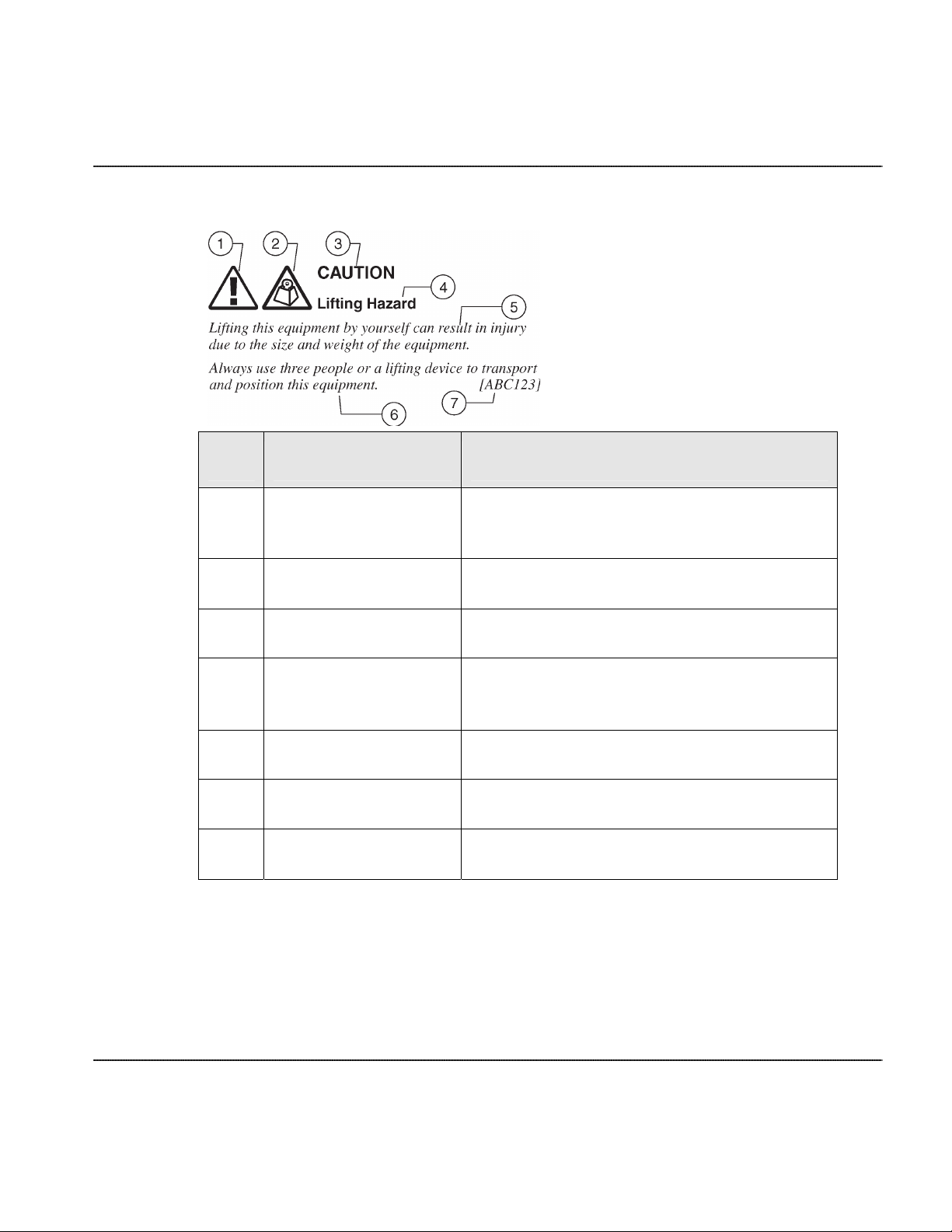
Hazard statements include the structural elements shown in the figure below.
viii Alcatel-Lucent 3FE-61830-AAAA-TCZZA
Edition 01 May 2008
Page 9
Overview About this document
Structure of hazard statements
Item Structure element Purpose
1 Personal injury symbol
Indicates the potential for personal injury
(optional).
2 Hazard type symbol Indicates hazard type (optional).
3 Signal word Indicates the severity of the hazard.
4 Hazard type
Describes the source of the risk of damage or
injury.
5 Damage statement Consequences if protective measures fail.
6 Avoidance message Protective measures to take to avoid the hazard.
7 Identifier The reference ID of the hazard statement (optional).
3FE-61830-AAAA-TCZZA Alcatel-Lucent ix
Edition 01 May 2008
Page 10

About this document Overview
Signal words
The following table defines signal words that identify the hazard severity levels.
Signal words for hazard severity
Signal word Meaning
DANGER
WARNING
CAUTION When used with the personal injury symbol:
Related information
The documentation set accompanying this family of routers includes this User Manual
and a Quick Installation Guide.
Technical support
Indicates an imminently hazardous situation (high risk) which, if not
avoided, will result in death or serious injury.
Indicates a potentially hazardous situation (medium risk) which, if not
avoided, could result in death or serious injury.
Indicates a potentially hazardous situation (low risk) which, if not
avoided, may result in personal injury.
When used without the personal injury symbol:
Indicates a potentially hazardous situation (low risk) which, if not
avoided, may result in property damage, such as service interruption or
damage to equipment or other materials.
For technical support, contact your local Alcatel-Lucent customer support team. See the
Alcatel-Lucent Support website (
x Alcatel-Lucent 3FE-61830-AAAA-TCZZA
Edition 01 May 2008
http://alcatel-lucent.com/support/
) for contact information.
Page 11

1 Product overview
Overview
Purpose
This chapter provides an introduction to the physical aspects of the CellPipe 7130 RG
3Ae.A2010, 3Ae.A2011, and 5Ae.A2010, including safety precautions and features.
Contents
All products are consolidated under the name CellPipe 7130 RG.
This chapter covers the following topics:
Hardware introduction 1-2
Safety precautions 1-2
Prerequisites 1-3
Descriptions of LEDs and interfaces 1-3
CellPipe 7130 RG features 1-6
3FE-61830-AAAA-TCZZA Alcatel-Lucent
Edition 01 May 2008
1-1
Page 12

Product overview Hardware introduction
Hardware introduction
The CellPipe 7130 RG supports multiple line modes. Using the high-speed ADSL
connection, the CellPipe 7130 RG provides users with broadband connectivity to the
Internet or an intranet. It provides downlink speeds of up to 24 Mb/s and uplink speeds of
up to 1 Mb/s.
The CellPipe 7130 RG 4-port wireless model provides wireless access to the Internet as a
WLAN access point or WLAN router. It is compliant with IEEE 802.11b/g specifications,
and complies with WEP, WPA, and WPA2 security specifications.
Safety precautions
Follow these recommendations to protect you and the CellPipe 7130 RG from harm:
• Use volume labels to mark the type of power.
• Use the power adapter provided with the CellPipe 7130 RG.
• Pay attention to the power load of the electrical outlet or extension cord. An
overburdened power outlet or damaged cords and plugs may cause electric shock or
fire. Check the power cords regularly. If you find any damage, replace the cord
immediately.
• Leave adequate space for heat dissipation to avoid any damage caused by overheating
the CellPipe 7130 RG. Do not cover the ventilation holes.
• Do not put the CellPipe 7130 RG near a heat source. Avoid placing the CellPipe 7130
RG in direct sunlight.
• Do not put the CellPipe 7130 RG in damp or wet locations. Do not spill any liquid on
the CellPipe 7130 RG.
• Do not connect the CellPipe 7130 RG to any PC or electronic product unless our
customer engineers or your ISP instructs you to do so; incorrect connections may
cause fires.
• Do not place the CellPipe 7130 RG on an unstable surface or support.
1-2 Alcatel-Lucent 3FE-61830-AAAA-TCZZA
Edition 01 May 2008
Page 13
Prerequisites Product overview
Prerequisites
Ensure that you have the following items before attempting to use the CellPipe 7130 RG:
•
Internet services subscription
•
10/100Base-T Ethernet NIC installed in your PC
•
Optional: HUB or Switch (required to attach to several PCs through a single Ethernet
interface on the CellPipe 7130 RG)
•
Operating system: Windows 98SE, Windows 2000, Windows ME, Windows XP,
Microsoft Vista, or Mac OS
•
Internet Explorer V5.0, Netscape V4.0, or Mozilla Firefox 1.5 or higher
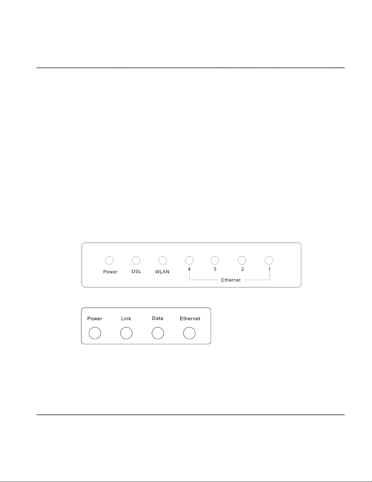
Descriptions of LEDs and interfaces
Figure 1-1 Front panel (4-port wireless model)
Figure 1-2 Front panel (1-port and 4-port model))
3FE-61830-AAAA-TCZZA Alcatel-Lucent 1-3
Edition 01 May 2008
Page 14

Product overview Descriptions of LEDs and interfaces
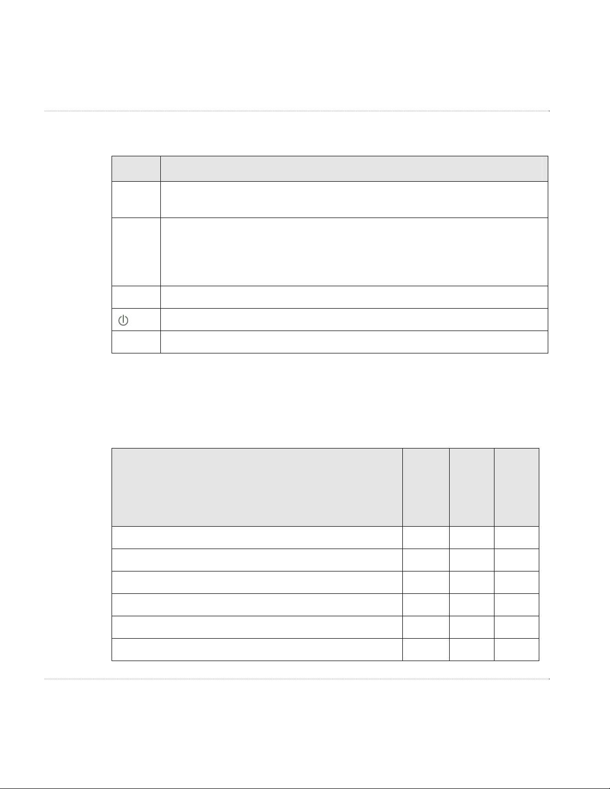
Table 1-1 Front panel LEDs
LED Color Status Descriptions
Power Green/Red
Off No power
Green
Red
Flashing Red Firmware upgrade
DSL (Link) Green
Off Initial self-test failed
Flashing
On
WLAN1 Green
Off Inactive
Flashing
CellPipe 7130 RG
startup OK
CellPipe 7130 RG
starting up
CellPipe 7130 RG is
detecting itself
Initial self-test of the
CellPipe 7130 RG is
OK and the CellPipe
7130 RG is ready
WLAN data is
flowing
On Active
Data2 Green
Off
Internet connection
failed
Flashing
Internet data is
flowing
On
Internet connection is
OK
1-4 Alcatel-Lucent 3FE-61830-AAAA-TCZZA
Edition 01 May 2008
1
4-port wireless model only.
2
1- and 4-port models only.
Page 15
Descriptions of LEDs and interfaces Product overview
LED Color Status Descriptions
Ethernet
Green
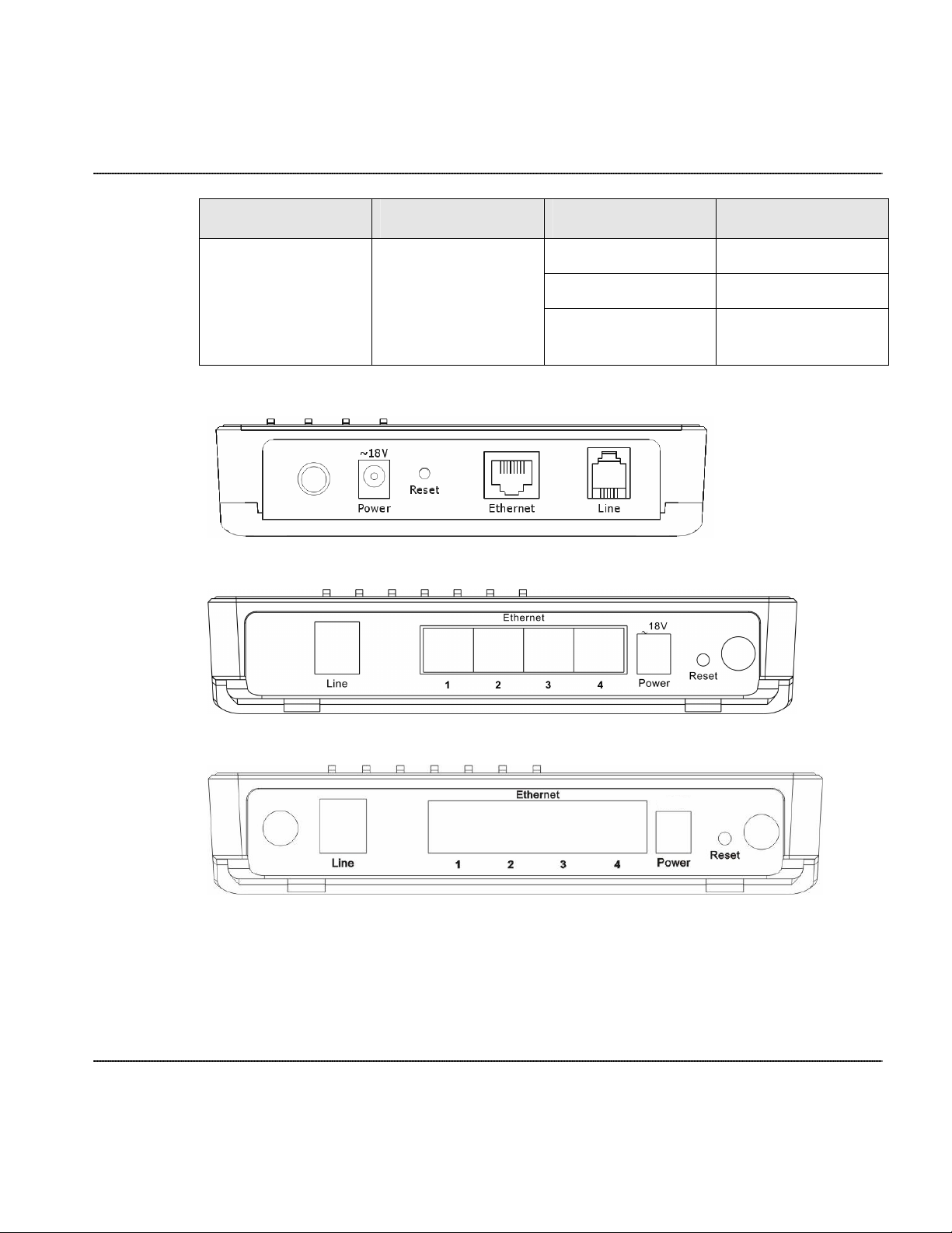
Figure 1-3 Rear panel (1-port model)
Table 1-2 Rear panel (4-port model)
Off No LAN link
Flashing LAN data flowing
On
LAN link established
and active
Figure 1-4 Rear panel (4-port wireless model)
3FE-61830-AAAA-TCZZA Alcatel-Lucent 1-5
Edition 01 May 2008
Page 16
Product overview CellPipe 7130 RG features
Table 1-3 Rear panel items
Items Usage
Line
Line RJ-11 port, used to connect the CellPipe 7130 RG to your ADSL (telephone)
line.
Reset Reset the CellPipe 7130 RG to its factory default settings.
Insert a small, blunt object (for example, a paper clip) into the hole while the
CellPipe 7130 RG is powered on. Press and hold the Reset button for 5 s to reset the
CellPipe 7130 RG.
Ethernet Ethernet RJ-45 port(s), used to connect the CellPipe 7130 RG to your PC(s).
Power on/ off
Power Power connector, used to connect the CellPipe 7130 RG to your electrical outlet.
CellPipe 7130 RG features
Table 1-4 Feature support by model
Feature supported
1-port
Ethernet
(3Ae.A2010)
4-port
Ethernet
(3Ae.A2011)
4-port
wireless
(5Ae.A2010)
Various line modes
External PPPoE dial-up access
Internal PPPoE/PPPoA dial-up access
Leased line mode
PPP IP extension
1483B/1483R/MER access
1-6 Alcatel-Lucent 3FE-61830-AAAA-TCZZA
Edition 01 May 2008
✓ ✓ ✓
✓ ✓ ✓
✓ ✓ ✓
✓ ✓ ✓
✓ ✓ ✓
✓ ✓ ✓
Page 17

CellPipe 7130 RG features Product overview
Feature supported
1-port
Ethernet
(3Ae.A2010)
4-port
Ethernet
(3Ae.A2011)
4-port
wireless
(5Ae.A2010)
Multiple PVCs (eight at most) and these PVCs can be isolated
from each other
Single PVC with multiple sessions
Multiple PVCs with multiple sessions
Binding of the ports and the PVCs
802.1Q and 802.1P protocols
DHCP server
NAT/NAPT
Static route
Firmware upgrade via Web, TFTP, FTP
Reset to factory default via hardware and software
DNS relay
Virtual server
DMZ functions
✓ ✓ ✓
✓ ✓ ✓
✓ ✓ ✓
✓ ✓ ✓
✓ ✓ ✓
✓ ✓ ✓
✓ ✓ ✓
✓ ✓ ✓
✓ ✓ ✓
✓ ✓ ✓
✓ ✓ ✓
✓ ✓ ✓
✓ ✓ ✓
Two-level passwords and usernames
Web interface
Telnet CLI
System status display
PPP session PAP/CHAP
IP filter function
IP QoS function
3FE-61830-AAAA-TCZZA Alcatel-Lucent 1-7
Edition 01 May 2008
✓ ✓ ✓
✓ ✓ ✓
✓ ✓ ✓
✓ ✓ ✓
✓ ✓ ✓
✓ ✓ ✓
✓ ✓ ✓
Page 18

Product overview CellPipe 7130 RG features
Feature supported
1-port
Ethernet
(3Ae.A2010)
4-port
Ethernet
(3Ae.A2011)
4-port
wireless
(5Ae.A2010)
Remote access control
Line connection status test
Remote management (Telnet, HTTP)
Configuration file backup and restore function
Ethernet supported such as Crossover Detection & Auto-
✓ ✓ ✓
✓ ✓ ✓
✓ ✓ ✓
✓ ✓ ✓
✓ ✓ ✓
Correction and polarity correction
UPnP
SIP ALG
1 Ethernet port, 10/100Base-T Auto MDI/MDIX
4 Ethernet ports, 10/100Base-T Auto MDI/MDIX
24 Mb/s downstream 1 Mb/s upstream
✓ ✓ ✓
✓ ✓ ✓
✓
✓ ✓
✓ ✓ ✓
1-8 Alcatel-Lucent 3FE-61830-AAAA-TCZZA
Edition 01 May 2008
Page 19

2 Hardware installation
Overview
Purpose
This chapter provides the instructions to install the CellPipe 7130 RG hardware.
Contents
This chapter covers the following topic:
To install the CellPipe 7130 RG 2-1
To install the CellPipe 7130 RG
Supplies
• Twisted pair category 5 Ethernet cable
• POTS splitter (Optional)
• CellPipe 7130 RG
• RJ-11 telephone cables
• Power adapter
3FE-61830-AAAA-TCZZA Alcatel-Lucent
Edition 01 May 2008
2-1
Page 20

Hardware installation To install the CellPipe 7130 RG
Before you begin
Caution
Potential for equipment or personal harm
Before installing the CellPipe 7130 RG, ensure you have thoroughly read the Safety
precautions in chapter 1.
Procedure
1 Connect the splitter, if necessary. The splitter has three RJ-11 ports:
• LINE - Connects to a telephone jack.
• ROUTER - Connects to the DSL jack of the CellPipe 7130 RG.
• PHONE - Connects to a telephone.
a. Connect the incoming telephone line to the LINE port of the splitter with a telephone
cable; see Figure 2-1.
b. Connect the DSL port of the CellPipe 7130 RG and the ROUTER port of the splitter
with a telephone cable.
c. Connect the telephone to the PHONE port of the splitter with a telephone cable.
Figure 2-1 shows how to connect of the CellPipe 7130 RG, splitter, and telephone.
2-2 Alcatel-Lucent 3FE-61830-AAAA-TCZZA
Edition 01 May 2008
Page 21

To install the CellPipe 7130 RG Hardware installation
Figure 2-1 CellPipe 7130 RG, splitter, and telephone connections (4-port
Ethernet model shown)
2 Connect the Ethernet port of the CellPipe 7130 RG to the network card of the PC using a
twisted pair category 5 Ethernet cable (MDI/MDIX).
3 Plug the power adapter into the wall outlet and connect the other end to the Power port of
the CellPipe 7130 RG.
E
ND OF STEPS
3FE-61830-AAAA-TCZZA Alcatel-Lucent 2-3
Edition 01 May 2008
Page 22

Page 23

3 Accessing the CellPipe 7130
RG configuration tool
Overview
Purpose
The following detailed procedure is intended for first time users to assist with CellPipe
7130 RG configuration.
Contents
This chapter covers the following topics:
To access the CellPipe 7130 RG configuration tool 3-1
To access the CellPipe 7130 RG configuration tool
When to use
Use this procedure to access the Web configuration interface of the CellPipe 7130 RG.
The configuration interface enables you to secure the CellPipe 7130 RG, limit access, set
traffic routes, modify passwords, and change advanced settings.
3FE-61830-AAAA-TCZZA Alcatel-Lucent
Edition 01 May 2008
3-1
Page 24

Accessing the CellPipe 7130 RG configuration tool To access the CellPipe 7130 RG configuration tool
Before you begin
Before you can configure the CellPipe 7130 RG, it must be installed, connected to a
Web-enabled PC, and turned on.
Procedure
1 Open a Web browser and enter the IP address of the CellPipe 7130 RG in the Address
bar:
http://192.168.1.1 ↵
2 Enter your username and password. There are two default accounts:
admin
and
user
The admin account has permission to configure the CellPipe 7130 RG settings and run
system diagnostics. The user account can view the CellPipe 7130 RG status, but cannot
alter the CellPipe 7130 RG settings. The admin password is
user
.
Figure 3-1 Login screen
admin
. The user password is
The System Status window appears. If you logged in as admin you can see CellPipe 7130
RG menus for Status, Wizard, LAN, WLAN3, WAN, Advance, and Admin. If you logged
in as user you can only see menus for Status and Admin. This window includes common
router, bridge, and PPPoE settings. The System Status window is described in chapter 4.
.
3-2 Alcatel-Lucent 3FE-61830-AAAA-TCZZA
Edition 01 May 2008
3
Wireless model only.
Page 25
To access the CellPipe 7130 RG configuration tool Accessing the CellPipe 7130 RG configuration tool
Figure 3-2 System Status window (4-port wireless model shown)
Once you have logged in for the first time, you should change the login password. See
“Password” in Chapter 10 for more information.
E
ND OF STEPS
3FE-61830-AAAA-TCZZA Alcatel-Lucent 3-3
Edition 01 May 2008
Page 26

Page 27

4 Status
Overview
Purpose
Select
Status
on the CellPipe 7130 RG menu bar to open the Status menu. This menu
contains the following items:
• System
• LAN
• WLAN
• WAN
• Port Mapping
• Statistic
• ARP Table (ARP)
Contents
4
This chapter covers the following topics:
System 4-2
LAN 4-4
4
4-port wireless model only.
5
4-port and 4-port wireless models only.
5
3FE-61830-AAAA-TCZZA Alcatel-Lucent
Edition 01 May 2008
4-1
Page 28
Status System
WLAN 4-5
WAN 4-7
Port Mapping 4-8
Statistic 4-10
ARP Table 4-13
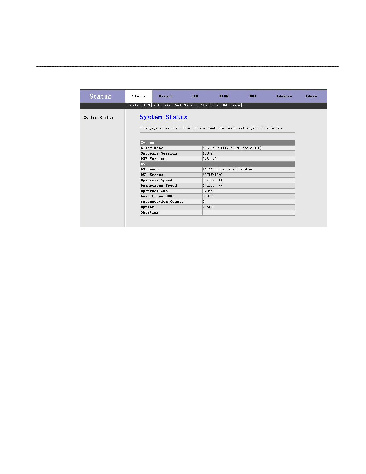
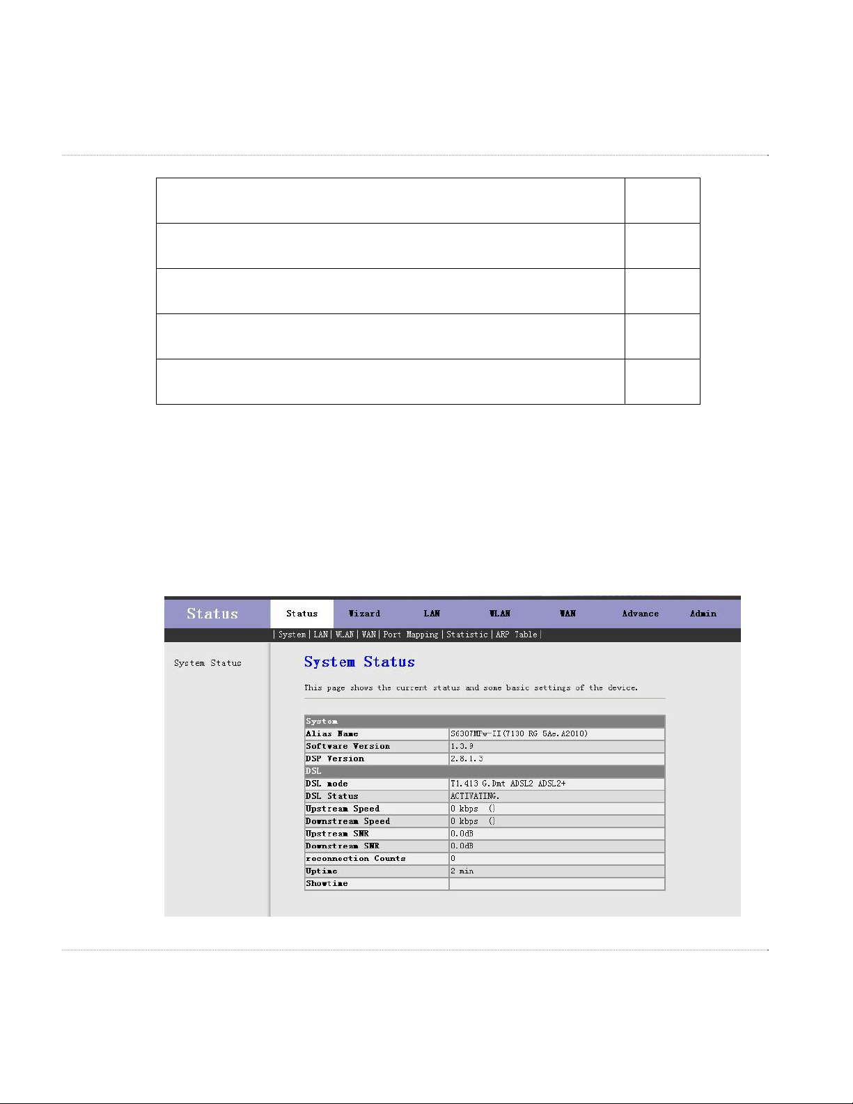
System
Select
System
in the Status menu to open the System Status window. In this window you
can view the current status and basic settings of the CellPipe 7130 RG.
Figure 4-1 System Status window (4-port wireless model shown)
The following table describes the fields of the System Status window.
4-2 Alcatel-Lucent 3FE-61830-AAAA-TCZZA
Edition 01 May 2008
Page 29

System Status
Table 4-1 Field descriptions
Field Description
System
Alias Name The product name.
Software Version
The latest software version installed in the
CellPipe 7130 RG.
DSP Version The DSP version of the chipset.
DSL
DSL mode
Indicates the configured ADSL
Modulation type for the CellPipe 7130
RG.
DSL Status
Indicates the current status of the CellPipe
7130 RG.
Upstream Speed
Indicates the current upstream transfer
speed.
Downstream Speed
Indicates the current downstream transfer
speed.
Upstream SNR
Indicates the upstream signal-to-noise
ratio.
Downstream SNR
Indicates the downstream signal-to-noise
ratio.
Reconnection Counts
Indicates how many times the DSL link
has reconnected.
Uptime
The length of time since the CellPipe 7130
RG was last rebooted.
Showtime
The length of time during which the
CellPipe 7130 RG was trained and
connected.
3FE-61830-AAAA-TCZZA Alcatel-Lucent 4-3
Edition 01 May 2008
Page 30

Status LAN
LAN
Select
LAN
in the Status menu to open the Lan Status window.
To alter these settings, see LAN Settings in chapter 6.
Figure 4-2 Lan Status window
The following table describes the fields of the Lan Status window.
Table 4-2 Field descriptions
Field Description
LAN Configuration
IP Address The IP address of the CellPipe 7130 RG.
Subnet Mask
DHCP Server
MAC Address
4-4 Alcatel-Lucent 3FE-61830-AAAA-TCZZA
Edition 01 May 2008
The subnet mask for the LAN IP
addresses.
If enabled, the CellPipe 7130 RG
functions as a DHCP server for LAN
clients
The MAC address of the CellPipe 7130
RG
Page 31

WLAN Status
Field Description
WLAN
DHCP Client Table
Select
WLAN
6
in the Status menu to open the WLAN Status window. In this window you
can view the parameters of the WLAN.
Figure 4-3 WLAN Status window
A listing of clients that received DHCPassigned IP addresses from the CellPipe
7130 RG.
The following table describes the fields of the WLAN Status window.
3FE-61830-AAAA-TCZZA Alcatel-Lucent 4-5
Edition 01 May 2008
6
4-port wireless model only.
Page 32

Status WLAN
Table 4-3 Field descriptions
Field Description
Wireless Configuration
Wireless
band
Mode
Broadcast SSID
root
Status
SSID
Authentication Mode
Indicates whether the wireless function is
enabled.
Indicates the wireless radio band standard
used by the CellPipe 7130 RG. The 802.11
b standard supports a maximum data rate
of 11 Mb/s. The 802.11 g standard
supports a maximum data rate of 54 Mb/s.
The wireless working mode, either AP or
AP+WDS.
Indicates whether the CellPipe 7130 RG
will broadcast its SSID (enabled).
Indicates whether the SSID has been
enabled.
Indicates the SSID assigned to the
CellPipe 7130 RG.
Indicates the authentication mode used by
the CellPipe 7130 RG.
Encrypt Mode
Indicates the encryption mode used by the
CellPipe 7130 RG.
vap0
Status Indicates the status of virtual AP0.
vap1
Status Indicates the status of virtual AP1.
vap2
4-6 Alcatel-Lucent 3FE-61830-AAAA-TCZZA
Edition 01 May 2008
Page 33

WAN Status
Field Description
Status Indicates the status of virtual AP2.
vap3
Status Indicates the status of virtual AP3.
WAN
Wireless Client List
Current Access Control List
Select
WAN
in the Status menu to open the WAN Status window. In this window you can
Lists the wireless devices that are
connected to the CellPipe 7130 RG
Indicates the access control mode and
MAC address list.
view status of the WAN, Default Gateway, and DNS Servers.
To configure the WAN, see “WAN Interface” in chapter 8.
Figure 4-4 WAN Status window
3FE-61830-AAAA-TCZZA Alcatel-Lucent 4-7
Edition 01 May 2008
Page 34

Status Port Mapping
The following table describes the fields of the WAN Status window.
Table 4-4 Field descriptions
Field Description
Interface The interface identifier.
VPI/VCI
Encap
Protocol
IP Address The IP address of the interface.
Gateway The gateway of the interface.
Status The status of the interface.
Default Gateway
DNS Servers
Port Mapping
The virtual path identifier and virtual
channel identifier of the listed interface.
The encapsulation type used by the
interface.
The protocol connection type of the
interface.
The default DSL gateway provided by
your ISP.
The default DSL DNS provided by your
ISP.
Select
Port Mapping
7
in the Status menu to open the Port Mapping window. In this
window you can view the mapping relation and the status of port mapping.
4-8 Alcatel-Lucent 3FE-61830-AAAA-TCZZA
Edition 01 May 2008
7
4-port and 4-port wireless models only
Page 35

Port Mapping Status
Figure 4-5 Port Mapping window
The following table describes the fields of the Port Mapping status window.
Table 4-5 Field descriptions
Field Description
Select The selected port mapping rule list.
Interface
The default group lists the port
information of the CellPipe 7130 RG.
Groups 1 to 4 list the ports that have been
mapped.
Priority
Indicates the priority of the port mapping
rules. There are four priority levels: Low,
Middle, High, or Highest.
3FE-61830-AAAA-TCZZA Alcatel-Lucent 4-9
Edition 01 May 2008
Page 36

Status Statistic
Statistic
Select
Statistic
which contains:
• Traffic Statistic
•
DSL Statistic
Traffic Statistic
Select
Traffic Statistic
window you can view the statistics of each network port.
Figure 4-6 Statistics -- Port window (4-port wireless model shown)
in the Status menu to open the statistics menu in the left-hand panel,
in the left-hand panel to open the Statistics -- Port window. In this
The following table describes the fields of the Statistics -- Port status window.
Table 4-6 Field descriptions
Field Description
Interface
Rx pkt The number of received packets.
Rx err The number of errored packets received.
4-10 Alcatel-Lucent 3FE-61830-AAAA-TCZZA
Edition 01 May 2008
The interface for which the statistics are
provided.
Page 37

Statistic Status
Field Description
Rx drop The number of received packets dropped.
Tx pkt The number of sent packets.
Tx err The number of errored sent packets.
Tx drop The number of sent packets dropped.
DSL Statistic
Select
DSL Statistic
in the left-hand panel to open the Statistics -- ADSL window. In this
window you can view the ADSL line statistics, downstream rates, and upstream rates.
Figure 4-7 Statistics – ADSL window
3FE-61830-AAAA-TCZZA Alcatel-Lucent 4-11
Edition 01 May 2008
Page 38

Status Statistic
The following table describes the fields of the Statistics -- ADSL status window.
Table 4-7 Field descriptions
Field Description
Mode One of:
• ADSL
• ADSL2
• ADSL2+
Latency
The latency mode, either Interleave or Fast
mode.
Trellis Coding
Whether trellis coding mode has been
enabled.
Status Whether the DSL link is connected.
Power Level The power management status.
SNR Margin The signal-to-noise status.
Attenuation The attenuation (dB).
Output Power
The power consumption of the DSL
upstream.
Attainable Rate
The maximum DSL data transmission
rate.
Rate The real-time DSL data transmission rate.
K (number of bytes in DMT frame) The number of bytes in the DMT frame.
R (number of check bytes in RS code
The length of the RS code word.
word)
S (RS code word size in DMT frame) The RS code length of the DMT frame.
D (interleaver depth)
The degree of the DSL status which his
working in interleaved mode.
Delay
4-12 Alcatel-Lucent 3FE-61830-AAAA-TCZZA
Edition 01 May 2008
The data transmission delay upstream and
Page 39

ARP Table Status
Field Description
downstream.
FEC Forward error correction.
CEC Cyclic redundancy check.
Total ES Total errored seconds.
Total SES Total severely errored seconds.
Total UAS Total unavailable seconds.
ARP Table
Select
ARP Table
in the Status menu to open the ARP Table window. In this window you
can view the ARP table which shows a list of learned MAC addresses. This helps you to
determine which MAC addresses have an IP address associated.
Figure 4-8 ARP Table window
3FE-61830-AAAA-TCZZA Alcatel-Lucent 4-13
Edition 01 May 2008
Page 40

Status ARP Table
The following table describes the fields of the ARP Table status window.
Table 4-8 Field descriptions
Field Description
IP Address
MAC Address
The IP addresses added to the ARP
routing table.
The MAC address associated with the IP
address in the ARP routing table.
4-14 Alcatel-Lucent 3FE-61830-AAAA-TCZZA
Edition 01 May 2008
Page 41

5 Wizard
Overview
Purpose
The CellPipe 7130 RG configuration wizard enables speedy and accurate configuration
of the CellPipe 7130 RG and Internet connection. The following sections describe the
configurable connection parameters. Each parameter has a default setting that is suitable
for most situations; however, you may modify these to suit your network environment.
Contents
This chapter covers the following topic:
To use the configuration wizard 5-1
To use the configuration wizard
When to use
This procedure describes how to use the configuration wizard to quickly set up the
CellPipe 7130 RG with the minimum required configurations.
Before you begin
When subscribing to a broadband service, you must know the method by which you are
connected to the Internet; your WAN device can be Ethernet, DSL, or both. Technical
3FE-61830-AAAA-TCZZA Alcatel-Lucent
Edition 01 May 2008
5-1
Page 42

Wizard To use the configuration wizard
information regarding the properties of your Internet connection should be provided by
your ISP. For example, your ISP should instruct you:
• whether you are connected to the Internet using a static or dynamic IP address
• which protocols, such as PPPoA or PPPoE, you must use to communicate over the
Internet
Please collect the following information from your ISP:
Procedure
VPI
VCI
Encapsulation: VC-MUX or
LLC
Protocol
Standard
Username/Password
Password protocol
1 Select
Wizard
in the CellPipe 7130 RG menu bar to open the Wizard menu. This menu
is available only for the admin user.
Caution
Possible service interruption
Do not change the VPI/VCI values unless instructed to do so by your ISP.
2 Select
Wizard
in the Wizard menu to open the Wizard window. In this window you can
configure the VPI and VCI for your ATM PVC.
Be sure to use the VPI and VCI numbers assigned to you. The valid range for VPI is 0 to
255 and for VCI is 32 to 65535 (0 to 31 is reserved for local management of ATM
traffic).
5-2 Alcatel-Lucent 3FE-61830-AAAA-TCZZA
Edition 01 May 2008
Page 43

To use the configuration wizard Wizard
Figure 5-1 Wizard window
3 Click
Next
. The Connection Type window appears. In this window you can select the
WAN Connection Type and the Encapsulation Mode as provided to you by your ISP.
Figure 5-2 Connection Type window
The following table describes the fields of the Connection Type window. Choose the
parameters that match the information provided by your ISP and click
Next
.
3FE-61830-AAAA-TCZZA Alcatel-Lucent 5-3
Edition 01 May 2008
Page 44

Wizard To use the configuration wizard
Table 5-1 Field descriptions
Field Description
WAN Connection Type The WAN Connection Type, one of:
• PPPoA
• PPPoE
• 1483 MER
• 1483 Routed
• 1483 Bridged
Encapsulation Mode
a. If you selected PPPoA or PPPoE as the connection type, go to step 4.
b. If you selected 1483 MER as the connection type, go to step 8.
c. If you selected 1483 Routed as the connection type, go to step 10.
d. If you selected 1483 Bridged as the connection type, go to step 11.
PPPoA and PPPoE configuration
4 If you selected PPPoA or PPPoE for the WAN Connection Type, configure the following
settings in the PPP configuration windows for the CellPipe 7130 RG type.
The method of encapsulation used by your
ISP, one of:
• LLC/SNAP
• VC-Mux
5-4 Alcatel-Lucent 3FE-61830-AAAA-TCZZA
Edition 01 May 2008
Page 45

To use the configuration wizard Wizard
Figure 5-3 WAN IP Settings window
The following table describes the fields of the WAN IP Settings window.
Table 5-2 Field descriptions
Field Description
Obtain an IP address automatically
The dynamic IP is not fixed; your ISP
assigns a different IP address each time you
connect to the network.
Use the following IP address
Specify a fixed IP address that is provided
by your ISP.
WAN IP address
The static IP address of the WAN interface
provided by your ISP, in dotted decimal
notation.
Enable NAT
Select the check box to enable the NAT
functions of the CellPipe 7130 RG. NAT
must be enabled if the CellPipe 7130 RG is
functioning as a router.
5 Click
Next
. The PPP Username and Password window appears. Set the field values
according to the information provided by your ISP.
3FE-61830-AAAA-TCZZA Alcatel-Lucent 5-5
Edition 01 May 2008
Page 46

Wizard To use the configuration wizard
Figure 5-4 PPP Username and Password window
The following table describes the fields of the PPP Username and Password window.
Figure 5-5 PPP Username and Password window
Field Description
PPP Username
The username and password apply to
PPPoE and PPPoA encapsulation only.
PPP Password
Ensure that you have entered the correct
PPP username and password provided by
your ISP.
5-6 Alcatel-Lucent 3FE-61830-AAAA-TCZZA
Edition 01 May 2008
Page 47

To use the configuration wizard Wizard
Field Description
PPP Connection Type The type of PPP connection, one of:
• Continuous (The connection is
established automatically, regardless of
the amount of traffic.)
• Connect on Demand (The
connection is only opened when traffic
must pass through an interface.)
• Manual (Used to connect to a location
once or occasionally – a user must log
in to the CellPipe 7130 RG and force
the connection open.)
The Idle Time value enables you to specify
the amount of time to wait (in seconds)
before the connection is dropped due to
inactivity.
6 Click
Next
. The LAN Interface Setup window appears. Set the field values according to
the needs of your local area network.
3FE-61830-AAAA-TCZZA Alcatel-Lucent 5-7
Edition 01 May 2008
Page 48

Wizard To use the configuration wizard
Figure 5-6 LAN Interface Setup window
The following table describes the fields of the LAN Interface Setup window.
Table 5-3 LAN Interface Setup window
Field Description
LAN IP
LAN Netmask
Enable Secondary IP
5-8 Alcatel-Lucent 3FE-61830-AAAA-TCZZA
Edition 01 May 2008
The IP address of the CellPipe 7130 RG in
dotted decimal notation; for example,
192.168.1.1(factory default).
The subnet mask of the LAN IP address;
for example 255.255.255.0.
Select this check box to enable the
secondary LAN IP address.
Page 49

To use the configuration wizard Wizard
Field Description
Secondary LAN IP
The secondary IP address of the CellPipe
7130 RG in dotted decimal notation; for
example, 192.168.100.1(factory default).
Secondary LAN Netmask
The subnet mask of the secondary LAN IP
address; for example 255.255.255.0.
Enable DHCP Server
Select this check box to enable the DHCP
server. The DHCP server assigns IP
addresses on request to devices connected
to the LAN.
Start IP
The first of the contiguous addresses in the
IP address pool.
End IP
The last of the contiguous addresses in the
IP address pool.
Max Lease Time
The maximum time period for which a
connected computer will maintain a LAN
IP address assigned by DHCP.
7 Click
Next
. The WAN Setup – Summary window appears. This window lists the WAN
configuration settings specified in steps 2 to 6. Click
reboot, or click
Back
to make changes. You have finished using the configuration wizard.
Finish
to save these settings and
3FE-61830-AAAA-TCZZA Alcatel-Lucent 5-9
Edition 01 May 2008
Page 50

Wizard To use the configuration wizard
Figure 5-7 WAN Setup – Summary window
1483 MER configuration
8 If you selected
1483 MER
as the WAN Connection Type in step 3, the WAN IP Settings
window appears.
5-10 Alcatel-Lucent 3FE-61830-AAAA-TCZZA
Edition 01 May 2008
Page 51

To use the configuration wizard Wizard
Figure 5-8 WAN IP Settings window
The following table describes the fields of the WAN IP Settings window.
Table 5-4 Field descriptions
Field Description
Obtain an IP address automatically
Use the following IP address
WAN IP Address
WAN Subnet Mask
Instructs the CellPipe 7130 RG to obtain a
WAN IP address automatically and enable
DHCP client functions.
When selected, this option instructs the
CellPipe 7130 RG to use the WAN IP address
provided in the WAN IP Address field.
The static IP address of the WAN interface
(provided by your ISP) in dotted decimal
notation.
The subnet mask for the IP address of the
WAN interface provided by your ISP; for
example, 255.255.255.0.
3FE-61830-AAAA-TCZZA Alcatel-Lucent 5-11
Edition 01 May 2008
Page 52

Wizard To use the configuration wizard
Field Description
Default Gateway
Obtain DNS server addresses automatically
Use the following DNS server addresses
Primary DNS server
Secondary DNS server
Enable NAT
The IP address of the default gateway to
access the Internet.
When selected, this option instructs the
CellPipe 7130 RG to obtain the IP address of
the DNS assigned by the uplink equipment
such as BAS.
When selected, this option instructs the
CellPipe 7130 RG to use the IP address of the
DNS specified in the Primary DNS server and
Secondary DNS server fields.
The IP address of the primary DNS provided
by your ISP, in dotted decimal notation.
The IP address of the secondary DNS
provided by your ISP, in dotted decimal
notation.
Select the check box to enable the NAT
functions of the CellPipe 7130 RG. NAT must
be enabled if the CellPipe 7130 RG is
functioning as a router.
Next
9 Click
configuration settings specified in steps 2, 3, and 8. Click
Back
1483 Routed configuration
10 If you selected
. The WAN Setup Summary window appears. This window lists the WAN
Finish
to save these settings, or
to make changes. You have finished using the configuration wizard.
1483 Routed
as the WAN Connection Type in step 3, the WAN IP
Settings window appears.
5-12 Alcatel-Lucent 3FE-61830-AAAA-TCZZA
Edition 01 May 2008
Page 53

To use the configuration wizard Wizard
Figure 5-9 WAN IP Settings window
The following table describes the fields of the WAN IP Settings window.
Table 5-5 Field descriptions
Field Description
None
Obtain an IP address automatically
Use the following IP address
3FE-61830-AAAA-TCZZA Alcatel-Lucent 5-13
Edition 01 May 2008
Select None to use the IP Unnumbered
function in 1483 Routed mode, which enables
IP processing on an interface without
assigning it an explicit IP.
Instructs the CellPipe 7130 RG to obtain a
WAN IP address automatically each time you
connect to the network.
When selected, this option instructs the
CellPipe 7130 RG to use the WAN IP address
provided in the WAN IP Address field.
Page 54

Wizard To use the configuration wizard
Field Description
WAN IP Address
WAN Subnet Mask
Obtain DNS server addresses automatically
Use the following DNS server addresses
Primary DNS server
Secondary DNS server
The static IP address of the WAN interface
(provided by your ISP) in dotted decimal
notation.
The subnet mask for the IP address of the
WAN interface provided by your ISP; for
example, 255.255.255.0.
When selected, this option instructs the
CellPipe 7130 RG to obtain the IP address of
the DNS assigned by the uplink equipment,
such as BAS.
When selected, this option instructs the
CellPipe 7130 RG to use the IP address of the
DNS specified in the Primary DNS server and
Secondary DNS server fields.
The IP address of the primary DNS provided
by your ISP, in dotted decimal notation.
The IP address of the secondary DNS
provided by your ISP, in dotted decimal
notation.
Enable NAT
Select the check box to enable the NAT
functions of the CellPipe 7130 RG. NAT must
be enabled if the CellPipe 7130 RG is
functioning as a router.
1483 Bridged configuration
11 The LAN Interface Setup window appears.
5-14 Alcatel-Lucent 3FE-61830-AAAA-TCZZA
Edition 01 May 2008
Page 55

To use the configuration wizard Wizard
Figure 5-10 LAN Interface Setup window
The following table describes the fields of the LAN Interface Setup window.
3FE-61830-AAAA-TCZZA Alcatel-Lucent 5-15
Edition 01 May 2008
Page 56

Wizard To use the configuration wizard
Table 5-6 Field descriptions
Field Description
LAN IP
Subnet Mask
Enable Secondary IP
Enable DHCP Server
Start IP
End IP
Max Lease Time
The IP address of the CellPipe 7130 RG in
dotted decimal notation; for example,
192.168.1.1(factory default).
The subnet mask of the LAN IP address; for
example 255.255.255.0.
Select this check box to enable the secondary
LAN IP address.
Select this check box to enable the DHCP
server. The DHCP server assign IP addresses
on request to devices connected to the LAN.
The first of the contiguous addresses in the IP
address pool.
The last of the contiguous addresses in the IP
address pool.
The maximum time period for which a
connected computer will maintain a LAN IP
address assigned by DHCP.
12 Click
5-16 Alcatel-Lucent 3FE-61830-AAAA-TCZZA
Edition 01 May 2008
Next
. The WAN Setup - Summary window appears.
Page 57

To use the configuration wizard Wizard
Figure 5-11 WAN Setup – Summary window
13 Click
Finish
to save these settings or
configuration wizard.
E
ND OF STEPS
Back
to make changes. You have finished using the
3FE-61830-AAAA-TCZZA Alcatel-Lucent 5-17
Edition 01 May 2008
Page 58

Page 59

6 LAN
Overview
Purpose
The LAN configuration windows are used to define the IP address of the CellPipe 7130
RG and to configure the DHCP server. Select
open the LAN menu, which contains
available only for the admin user.
LAN
LAN Settings
in the CellPipe 7130 RG menu bar to
and
DHCP Settings
. This menu is
Contents
This chapter covers the following topics:
LAN Settings 6-1
DHCP Settings 6-3
LAN Settings
On the LAN Interface Setup window you can configure the LAN IP address of the
CellPipe 7130 RG. The default IP address is 192.168.1.1 and is acceptable for most
network environments. This is the address at which the CellPipe 7130 RG can be reached
in the local network. This address can be freely assigned from the block of available
private addresses.
3FE-61830-AAAA-TCZZA Alcatel-Lucent
Edition 01 May 2008
6-1
Page 60

LAN LAN Settings
Select
LAN Settings
in the LAN menu to open the LAN Interface Setup window.
Figure 6-1 LAN Interface Setup window (4-port wireless model shown)
The following table describes the fields of the LAN Interface Setup window.
Table 6-1 Field descriptions
Field Description
Interface Name
IP Address
Subnet Mask
Secondary IP
The preset name of the LAN interface you
are configuring.
The IP address of the LAN interface in dotted
decimal notation. The default is 192.168.1.1.
You can change this address as needed to an
address that is reserved for private use. The
range of private addresses is 192.168.1.1 to
192.168.255.254.
The subnet mask of the IP addresses in your
LAN; for example, 255.255.255.0.
Select the check box to enable the secondary
LAN IP address. The primary and secondary
LAN IP addresses must be different.
6-2 Alcatel-Lucent 3FE-61830-AAAA-TCZZA
Edition 01 May 2008
Page 61

DHCP Settings LAN
Field Description
IGMP Snooping8
Apply Changes Click to save your changes.
DHCP Settings
DHCP allows network clients (computers) to obtain their TCP/IP configuration settings
at start-up from a centralized DHCP server. A DHCP server can assign an IP address, IP
default gateway, and DNS to DHCP clients. You can enable or disable the CellPipe 7130
RG as a DHCP server. The CellPipe 7130 RG can also act as a surrogate DHCP server
(DHCP Proxy) whereby it relays the IP address assignment from another DHCP server to
the network clients.
Select
Depending on the DHCP function enabled, different fields are visible. The following
figures show the three DHCP functions with their associated fields.
DHCP Settings
Select the Enabled radio button to have the
CellPipe 7130 RG glean routing information
from IGMP packets.
in the LAN menu to open the DHCP Server Setup window.
Figure 6-2 DHCP Server Setup window – Disable selected
3FE-61830-AAAA-TCZZA Alcatel-Lucent 6-3
Edition 01 May 2008
8
4-port wireless model only
Page 62

LAN DHCP Settings
Figure 6-3 DHCP Server Setup window – DHCP Proxy selected
Figure 6-4 DHCP Server Setup window – DHCP Server selected
The following table describes the fields of the DHCP Server Setup window. Not all fields
apply to each DHCP function.
6-4 Alcatel-Lucent 3FE-61830-AAAA-TCZZA
Edition 01 May 2008
Page 63

DHCP Settings LAN
Table 6-2 Field descriptions
Field Description
Disable
The CellPipe 7130 RG does not function as a
DHCP server or proxy.
DHCP Proxy
If enabled, the CellPipe 7130 RG functions as
a surrogate DHCP server and relays the
DHCP requests and responses between the
remote server and the client. Configure the
DHCP Server Address.
DHCP Server Address The IP address of the remote DHCP server.
DHCP Server
If enabled, the CellPipe 7130 RG assigns IP
addresses, an IP default gateway, and DNS
servers to computers that support the DHCP
client; for example, Windows 95, Windows
NT.
IP Pool Range
The first value and the last value of
contiguous IP addresses for the IP address
pool.
Show Client
Click to view the assigned IP address(es) of
the clients; see Figure 6-5.
Max Lease Time
The time period during which the computers
retain the IP addresses assigned to them
without changing them.
Domain Name
If left blank, the CellPipe 7130 RG uses the
domain name obtained by DHCP from the
ISP. Although you must enter a System
Name on each individual computer, the
domain name can be assigned to the CellPipe
7130 RG via the DHCP server.
Gateway Address
The default IP gateway of the IP address
pool.
3FE-61830-AAAA-TCZZA Alcatel-Lucent 6-5
Edition 01 May 2008
Page 64

LAN DHCP Settings
Field Description
MAC-Base Assignment
Apply Changes Click to save your changes.
When you click the
Figure 6-5 Active DHCP Client Table window
Show Client
button, the Active DHCP Client Table window appears.
Click to assign LAN IP addresses to specific
computers based on their MAC address; see
Figure 6-6.
The following table describes the fields in the Active DHCP Client Table window.
Table 6-3 Field descriptions
Field Description
IP Address
MAC Address
Time Expired(s)
When you click the
MAC-Base Assignment
The IP address related to the MAC
address.
The MAC address of the DHCP client
(computer).
The lease time. The time period during
which computers retain their DHCPassigned IP addresses.
button, the Static IP Assignment Table
window appears. In this window, you can assign LAN IP address to a computer based on
its MAC address.
6-6 Alcatel-Lucent 3FE-61830-AAAA-TCZZA
Edition 01 May 2008
Page 65

DHCP Settings LAN
Figure 6-6 Static IP Assignment Table window
The following table describes the fields of the Static IP Assignment Table window.
Table 6-4 Field descriptions
Field Description
Host MAC Address
The MAC address of a computer on your
LAN.
Assigned IP Address
The static IP address to assign to the
computer from the private IP address
pool.
Assign IP
Click to have this IP address /MAC
association take effect. A row is added to
the MAC-Base Assignment Table.
Modify Assigned IP
Select a row in MAC-Base Assignment
Table; the Host MAC Address and
Assigned IP Address fields are
populated with this data. Update the
MAC or IP address fields and click
Modify Assigned IP to save the
changes.
3FE-61830-AAAA-TCZZA Alcatel-Lucent 6-7
Edition 01 May 2008
Page 66

LAN DHCP Settings
Field Description
Delete Assigned IP
Select a row in MAC-Base Assignment
Table and click Delete Assigned IP to
delete this row.
Close Click to close this window.
MAC-Base Assignment Table
Shows the assigned IP address associated
the MAC address.
6-8 Alcatel-Lucent 3FE-61830-AAAA-TCZZA
Edition 01 May 2008
Page 67

7 WLAN
Overview
Purpose
Contents
Note:
This menu is only available for the CellPipe 7130 RG 5Ae.A2010.
This section introduces the wireless LAN and some basic WLAN configurations for the
CellPipe 7130 RG (4-port wireless model). Wireless LANs can be as simple as two
computers with wireless LAN cards communicating in a peer-to-peer network, or as
complex as many computers with WLAN cards communicating through access points
which bridge network traffic to a wired LAN.
Select
WLAN
on the CellPipe 7130 RG menu bar to open the WLAN sub-menu, which
contains the following items:
• Basic Settings
• Security
• Advance Settings
• Access Control
• WDS Settings
This menu is available only for the admin user.
This chapter covers the following topics:
Basic Settings 7-2
3FE-61830-AAAA-TCZZA Alcatel-Lucent
Edition 01 May 2008
7-1
Page 68

WLAN Basic Settings
Security 7-6
Advance Settings 7-10
Access Control 7-12
WDS Settings 7-14
Basic Settings
Select
Basic Settings
in the WLAN sub-menu to open the Wireless Basic Settings
window. This window is used to configure the parameters for wireless LAN clients that
may connect to your access point.
Figure 7-1 Wireless Basic Settings window
7-2 Alcatel-Lucent 3FE-61830-AAAA-TCZZA
Edition 01 May 2008
Page 69

Basic Settings WLAN
The following table describes the fields of the Wireless Basic Settings window.
Table 7-1 Field descriptions
Field Description
Disable Wireless LAN Interface
The wireless LAN is turned on by
default. Select the check box to disable
the wireless LAN.
Band
The radio band used by the wireless
transmissions.
Mode Choose between:
• AP
• AP+WDS
To configure WDS, see WDS Settings.
(Root) SSID
The SSID is a unique name to identify
the CellPipe 7130 RG in the wireless
LAN. Wireless devices (i.e.
computers) that connect to the CellPipe
7130 RG must have the same SSID.
Enter a descriptive name.
Auth Type
The authentication type the CellPipe
7130 RG uses when devices connect to
the CellPipe 7130 RG; choose between
Open, Shared Key, and Auto.
Virtual SSID
You can enable a maximum of four
SSIDs. Click Set VSSID, the Virtual
Set VSSID
SSID window appears; see Figure 7-2.
SSID You can enable or disable this SSID.
Country/Area Select your geographical region.
3FE-61830-AAAA-TCZZA Alcatel-Lucent 7-3
Edition 01 May 2008
Page 70

WLAN Basic Settings
Field Description
Channel Number
Send Rate
A channel is the radio frequency used
by an 802.11b/g wireless device. The
channels that are available depend on
your geographical area. If another
access point is nearby, use a different
channel to reduce signal interference.
Interference occurs when the radio
signal from a different access point
overlaps with your signal, degrading
performance.
Select a channel number from the
drop-down list.
The rate of the data transmission.
Choose between:
• 11Mb/s for 802.11b networks
• 54 Mb/s for 802.11g networks
• Auto, to adjust automatically to the
available data transmission rate of
the current wireless network.
Radio Power (mW)
The radio transmission power
consumption. The greater the power
consumption, the farther the signal will
reach.
Apply Changes Click to save your changes.
When you click
7-4 Alcatel-Lucent 3FE-61830-AAAA-TCZZA
Edition 01 May 2008
Set VSSID
, the Virtual SSID Setting window appears.
Page 71

Basic Settings WLAN
Figure 7-2 Virtual SSID Setting window
The following table describes the fields of the Virtual SSID Setting window.
Table 7-2 Field descriptions
Field Description
Vap0 to Vap3: Enable
Select the check box to enable this
virtual SSID.
SSID
The SSID is a unique name to identify
the virtual access point in the wireless
LAN.
Auth Type
The authentication type the virtual
access point uses when devices
connect to it; choose among Open,
Shared Key, and Auto.
Apply Changes Click to save your changes.
Undo
Click to clear your changes to this
window.
3FE-61830-AAAA-TCZZA Alcatel-Lucent 7-5
Edition 01 May 2008
Page 72

WLAN Security
Security
Click
Security
Wireless security is vital to protect wireless communications between wireless stations,
access points, and the wired network.
Figure 7-3 Wireless Security Setup window
in the WLAN menu to open the Wireless Security Setup window.
The following table describes the fields of the Wireless Security Setup screen.
Table 7-3 Field descriptions
Field Description
SSID Type
7-6 Alcatel-Lucent 3FE-61830-AAAA-TCZZA
Edition 01 May 2008
Select root if you are setting up
security parameters for the Root SSID.
If you set more than one SSID (virtual
SSID), the type of the SSID is shown.
Page 73

Security WLAN
Field Description
Encryption Choose between:
• None - No encryption
• WEP - Encrypts data frames before
transmitting them over the wireless
network.
• WPA (TKIP) - WPA is a subset of
the IEEE 802.11i security
specification draft. Key differences
between WPA and WEP are user
authentication and improved data
encryption.
• WPA2 (AES) – WPA with an AES
algorithm.
• WPA2 Mixed – allows WPA and
WPA2 clients to be associated with
the same SSID.
Set WEP Key
This button becomes active when you
select WEP as the Encryption type.
Click to set up the WEP key; see
Figure 7-4.
Use 802.1x Authentication
Select the check box to enable
authentication security for the CellPipe
7130 RG. Choose WEP-64bits or
WEP-128bits to specify the length of
authentication key to use. Longer keys
are more secure.
WPA Authentication Mode
Select Enterprise to obtain your
authentication key from an
authentication server.
Select Personal to specify your own
authentication key which must be
shared with every LAN device that will
access the CellPipe 7130 RG.
3FE-61830-AAAA-TCZZA Alcatel-Lucent 7-7
Edition 01 May 2008
Page 74

WLAN Security
Field Description
Pre-Shared Key Format
Pre-Shared Key
Authentication RADIUS Server
Port
Choose one of the following as the
format for your authentication key:
• Passphrase (e.g. the quick brown
fox)
• Password (e.g. b1tjl194)
• Hexadecimal (e.g. 65E4 E556
83EF A6DE)
A value for your authentication key is
preset.
RADIUS is based on a client-server
model that supports authentication,
authorization, and accounting. The
access point is the client and the server
is the RADIUS server. RADIUS is a
simple package exchange in which the
CellPipe 7130 RG acts as a message
relay between the wireless station and
the network RADIUS server.
The default port of the RADIUS server
for authentication is 1812. Do not
change this value unless your network
administrator instructs you to do so.
IP Address
Enter the IP address of the RADIUS
server.
Password
Enter a password as the key to be
shared between the external
authentication server and the access
point; the key is not sent over the
network. This key must be the same on
the external authentication server and
the CellPipe 7130 RG.
Apply Changes Click to save your changes.
7-8 Alcatel-Lucent 3FE-61830-AAAA-TCZZA
Edition 01 May 2008
Page 75

Security WLAN
Figure 7-4 Wireless WEP Key Setup window
The following table describes the fields of the Wireless WEP Key Setup window.
Table 7-4 Field descriptions
Field Description
SSID Type The SSID type of the CellPipe 7130 RG.
Key Length
Select 64-bit or 128-bit to use data
encryption.
Key Format
If you chose 64-bit as the Key Length, you
can choose ASCII (5 characters) or Hex (10
characters).
If you chose 128-bit as the Key Length, you
can choose ASCII (13 characters) or Hex
(26 characters).
Default Tx Key
Specifies the default Encryption Key to be
used.
Encryption Key 1 to 4
The Encryption keys are used to encrypt data.
Both the CellPipe 7130 RG and the wireless
clients must use the same encryption key for
3FE-61830-AAAA-TCZZA Alcatel-Lucent 7-9
Edition 01 May 2008
Page 76

WLAN Advance Settings
Field Description
data transmission.
If you chose ASCII (5 characters) as the Key
Format, then enter any 5 ASCII characters.
If you chose Hex (10 characters) as the Key
Format, then enter any 10 hexadecimal
characters.
If you chose ASCII (13 characters) as the
Key Format, then enter any 13 ASCII
characters.
If you chose Hex (26 characters) as the Key
Format, then enter any 26 hexadecimal
characters.
Apply Changes Click to save your changes.
Close Click to close this window.
Undo Click to clear your changes to this window.
Advance Settings
Click
Advance Settings
window. These settings are only for technically advanced users who have a sufficient
knowledge about wireless LANs. These settings should not be changed unless you are
aware of the effect these changes may have on your access point.
in the WLAN menu to open the Wireless Advanced Settings
7-10 Alcatel-Lucent 3FE-61830-AAAA-TCZZA
Edition 01 May 2008
Page 77

Advance Settings WLAN
Figure 7-5 Wireless Advanced Settings window
The following table describes the fields of the Wireless Advanced Settings window.
Table 7-5 Field descriptions
Field Description
Fragment Threshold
The maximum data fragment size that can be
sent in the wireless network before the
CellPipe 7130 RG will fragment the packet
into smaller data frames.
RTS Threshold
RTS is designed to prevent collisions due to
a hidden node. An RTS threshold defines the
biggest data frame size you can send before
an RTS handshake occurs. The RTS
Threshold value is between 0 and 2347.
If the RTS Threshold value is greater than
the Fragment Threshold value, then the
RTS handshake will never occur as the data
frames will be fragmented before they reach
RTS size.
3FE-61830-AAAA-TCZZA Alcatel-Lucent 7-11
Edition 01 May 2008
Page 78

WLAN Access Control
Field Description
Beacon Interval
Preamble Type
Relay Interval
LAN/WLAN Interval
Apply Changes Click to save your changes.
The amount of time between beacon
transmissions. A beacon is a packet
broadcast by the access point to keep the
network synchronized, and can identify the
presence of an access point.
Choose whether to use a long or short PLCP
preamble to create the PPDU (PLCP
protocol data unit). Auto is recommended.
When enabled, connected clients can’t
communicate with each other within the
local wireless network.
When enabled, connected clients can’t
communicate with each other within the
local wireless network.
Access Control
Click
Access Control
7-12 Alcatel-Lucent 3FE-61830-AAAA-TCZZA
Edition 01 May 2008
in the WLAN menu to open the Wireless Access Control window.
Page 79

Access Control WLAN
Figure 7-6 Wireless Access Control window
The following table describes the fields of the Wireless Access Control window.
Table 7-6 Field descriptions
Field Description
Select Access Control Mode Choose among:
• Disable
• Allow Listed - permits access to the
CellPipe 7130 RG, MAC addresses
listed will be allowed to access the
CellPipe 7130 RG.
• Deny Listed - blocks access to the
CellPipe 7130 RG, MAC addresses
listed will be denied to access the
CellPipe 7130 RG.
Apply Changes Click to save your changes.
3FE-61830-AAAA-TCZZA Alcatel-Lucent 7-13
Edition 01 May 2008
Page 80

WLAN WDS Settings
Field Description
MAC Addr
Apply Changes Click to add the MAC address to the ACL.
Reset Click to clear the MAC address field.
Current Access Control List
Delete
Delete All
WDS Settings
The MAC address of the wireless clients
that are allowed or denied access to the
CellPipe 7130 RG.
The MAC addresses in this table are
allowed or denied access to the CellPipe
7130 RG depending on the selected
Access Control Mode.
Select a row in the Current Access Control
List table and click to delete the row.
Click to delete all rows in the Current
Access Control List table.
Click
WDS Settings
in the WLAN menu to open the WDS Settings window.
Wireless Distribution System is commonly used in areas requiring multiple access points,
where wiring is not possible or costly, and for providing backup paths between access
points.
Note:
You must select the
AP+WDS
option on the Wireless Basic Settings window;
see Basic Settings, before you configure this window.
7-14 Alcatel-Lucent 3FE-61830-AAAA-TCZZA
Edition 01 May 2008
Page 81

WDS Settings WLAN
Figure 7-7 WDS Settings window
The following table describes the fields of the WDS Settings window.
Table 7-7 Field descriptions
Field Description
Enable WDS
MAC Addr The MAC address of the access point.
Comment A comment to describe the access point.
Apply Changes
Reset
Current WDS AP List
3FE-61830-AAAA-TCZZA Alcatel-Lucent 7-15
Edition 01 May 2008
Select the check box to enable the WDS
function and set the WDS parameters.
Click to add the access point MAC address
and comment to the Current WDS AP List.
Click to clear the MAC Addr and
Comment fields.
A listing of the access points added to the
WDS.
Page 82

WLAN WDS Settings
Field Description
Delete
Delete All
Select a row in the Current WDS AP List
table and click to delete the row.
Click to delete all rows in the Current WDS
AP List table.
7-16 Alcatel-Lucent 3FE-61830-AAAA-TCZZA
Edition 01 May 2008
Page 83

8 WAN
Overview
Purpose
Click
WAN
in the CellPipe 7130 RG menu bar to open the WAN menu, which contains
WAN Interface
and
ADSL Settings
. This menu is available only for the admin user.
Contents
This chapter covers the following topics:
WAN Interface 8-1
ADSL Settings 8-10
WAN Interface
Click
WAN Interface
this window you can configure the parameters for the channel operation modes of the
CellPipe 7130 RG.
in the WAN menu to open the Channel Configuration window. In
3FE-61830-AAAA-TCZZA Alcatel-Lucent
Edition 01 May 2008
8-1
Page 84

WAN WAN Interface
Figure 8-1 Channel Configuration window
The following table describes the fields of the Channel Configuration window.
Table 8-1 Field descriptions
Field Description
Current ATM VC Table
8-2 Alcatel-Lucent 3FE-61830-AAAA-TCZZA
Edition 01 May 2008
This table lists the PVCs that have
already been created. It shows the
Interface name, Channel Mode, VPI/VCI,
Encapsulation mode, NAPT status, local
IP address, remote IP address, user name,
default route, and status. The maximum
number of entries in this table is eight.
Page 85

WAN Interface WAN
Field Description
Click this button; the PPP Interface Modify window appears. In this window
you can modify the PVC parameters;
however, the default settings are
recommended.
VPI
The identifier for a virtual path between
two points in an ATM network; a value
between 0 and 255.
VCI
The identifier for a virtual channel
between two points in an ATM network;
a value between 32 and 65535 (1 to 31
are reserved for known protocols).
Encapsulation Choose between LLC and VC-Mux.
Channel Mode Choose among:
• 1483 Bridged
• 1483 MER
• PPPoE
• PPPoA
• 1483 Routed
Application Mode Choose Internet.
Admin Status
Enable or disable the PVC. When
disabled, this PVC is unusable.
Enable NAPT
Select the check box to enable the NAPT
functions of the CellPipe 7130 RG.
NAPT must be enabled if the CellPipe
7130 RG is functioning as a router.
Login Name The user name provided by your ISP.
Password The password provided by your ISP.
3FE-61830-AAAA-TCZZA Alcatel-Lucent 8-3
Edition 01 May 2008
Page 86

WAN WAN Interface
Field Description
Connection Type Choose among:
• Continuous (the connection is
established automatically, regardless
of the amount of traffic)
• Connect on Demand (the
connection is only opened when
traffic must pass through an
interface)
• Manual (used to connect to a
location once or occasionally – a user
must log in to the CellPipe 7130 RG
and force the connection open).
Idle Time(min)
If you selected Connect on Demand as
the Connection Type, you must specify
the idle time. If the CellPipe 7130 RG
detects no traffic from the user for the
amount of time specified, the CellPipe
7130 RG will automatically disconnect
the PPPoE connection.
Type Choose between:
• Fixed IP - enter the Local IP
address, remote IP address, and
subnet mask.
• Use DHCP - the CellPipe 7130 RG
functions as a DHCP proxy; the
WAN IP address is assigned by the
remote DHCP server.
Local IP Address
The IP of WAN interface provided by
your ISP.
Remote IP Address The gateway IP provided by your ISP.
Subnet Mask The subnet mask of the Local IP Address.
8-4 Alcatel-Lucent 3FE-61830-AAAA-TCZZA
Edition 01 May 2008
Page 87

WAN Interface WAN
Field Description
Unnumbered
Select the check box to enable the
unnumbered IP function. Using an
unnumbered IP interface allows you to
borrow an IP address already configured
on one of the other interfaces of the
CellPipe 7130 RG.
Default Route
Enable the default route function when
you are configuring PPPoA, PPPoE,
1483 Routed and 1483 MER connections.
Add
Click to add the new PVC to the Current
ATM VC Table.
Modify
Select a PVC in the Current ATM VC
Table and modify the settings of this
PVC. Click Modify to save your
changes.
Delete
Select a PVC in the Current ATM VC
Table and click to delete this PVC.
Undo Click to clear the parameter fields.
ATM Setting
Click to configure the QoS mode of the
ATM PVC; see Figure 8-3. The default
settings are recommended.
If the PVC uses PPP as the channel mode, click in the Current ATM VC Table; the
PPP Interface – Modify window appears. In this window you can configure the
parameters of the selected PPPoE PVC.
3FE-61830-AAAA-TCZZA Alcatel-Lucent 8-5
Edition 01 May 2008
Page 88

WAN WAN Interface
Figure 8-2 PPP Interface – Modify window (4-port wireless model shown)
The following table describes the fields of the PPP Interface - Modify window.
Table 8-2 Field descriptions
Field Description
PPP Interface The preset identifier of the PPP Interface
Protocol
ATM VCC
Status
8-6 Alcatel-Lucent 3FE-61830-AAAA-TCZZA
Edition 01 May 2008
The protocol type used for this WAN
connection.
The ATM virtual circuit connection
assigned for this PPP interface (VPI/VCI)
The status of the PVC you are
configuring.
Page 89

WAN Interface WAN
Field Description
Login Name The login name provided by your ISP.
Password The password provided by your ISP.
Authentication Method Choose among:
• PAP
• CHAP
• Auto
Connection Type Choose among:
• Continuous
• Connect on Demand
• Manual
Idle Time
Auto Disconnect Time9
Warn Disconnect Delay9
Default Route
MTU/MRU
If the CellPipe 7130 RG detects no traffic
from the user for the amount of time
specified, the CellPipe 7130 RG will
automatically disconnect the PPPoE
connection.
If set, the CellPipe 7130 RG disconnects
automatically, even if data is being
transmitted.
If the Auto Disconnect Time is set, you
can configure a warning period that will
follow the disconnect time, after which
the CellPipe 7130 RG disconnects.
Enable the default route function when
you are configuring PPPoA, PPPoE,
1483 Routed and 1483 MER connections.
The size of the largest packet or frame
that can be transmitted.
3FE-61830-AAAA-TCZZA Alcatel-Lucent 8-7
Edition 01 May 2008
9
4-port wireless model only.
Page 90

WAN WAN Interface
Field Description
IP Address
Choose a dynamic or static IP address for
the WAN interface, as prescribed by your
ISP.
Bridge Choose among:
• Bridged Ethernet
• Bridged PPPoE
• Disable Bridge
AC-Name The accessed equipment type.
Service-Name9 The service name.
802.1q9
Specifies whether VLAN tagging should
be used.
VLAN ID9
The unique number assigned to this
virtual LAN.
Apply Changes Click to save your changes.
Return
Click to return to the Channel
Configuration window.
Undo
Click to clear the values of the fields in
this window
Click
ATM Setting
in the Channel Configuration window; the ATM Setting window
appears. In this window you can configure the ATM parameters for the CellPipe 7130
RG, including the QoS type, PCR, CDVT, SCR, and MBS.
8-8 Alcatel-Lucent 3FE-61830-AAAA-TCZZA
Edition 01 May 2008
Page 91

WAN Interface WAN
Figure 8-3 ATM Setting window
The following table describes the fields of the ATM Setting window.
Table 8-3 Field descriptions
Field Description
VPI
The virtual path identifier of the ATM
PVC.
VCI
The virtual channel identifier of the ATM
PVC.
QoS
The QoS category of the PVC; choose
among:
• UBR
• CBR
• rt-VBR
• nrt-VBR
PCR
The maximum rate at which cells can be
transported along a connection in the
ATM network.
CDVT
The amount of delay permitted between
ATM cells (expressed in microseconds).
3FE-61830-AAAA-TCZZA Alcatel-Lucent 8-9
Edition 01 May 2008
Page 92

WAN ADSL Settings
Field Description
SCR
MBS
Apply Changes Click to save your changes.
Undo Click to clear all fields.
Close Click to close the window.
ADSL Settings
Click
ADSL Interface
window you can select the DSL modulation. In most network environments, the default
settings are acceptable. The CellPipe 7130 RG supports the following modulations:
• G.Dmt
• G.Lite
The maximum rate that traffic can pass
over a PVC without the risk of cell loss.
The maximum number of cells that can be
transmitted at the PCR.
in the WAN menu to open the ADSL Settings window. In this
• T1.413
• ADSL2
• ADSL2+
• AnnexL
• AnnexM
The CellPipe 7130 RG negotiates the modulation mode with the DSLAM.
8-10 Alcatel-Lucent 3FE-61830-AAAA-TCZZA
Edition 01 May 2008
Page 93

ADSL Settings WAN
Figure 8-4 ADSL Settings window
The following table describes the fields of the ADSL Settings window.
Table 8-4 Field descriptions
Field Description
ADSL Modulation Choose among:
• G.Lite – 1.5 Mb/s downstream, 512 Kb/s
upstream
• G.Dmt – 8 Mb/s downstream, 864 Kb/s
upstream
• T1.413 – max 15 Mb/s downstream, max
1.5 Mb/s upstream
• ADSL – 1.5 to 9 Mb/s downstream, 16 to
640 Kb/s upstream
• ADSL2+ – 24 Mb/s downstream
3FE-61830-AAAA-TCZZA Alcatel-Lucent 8-11
Edition 01 May 2008
Page 94

WAN ADSL Settings
Field Description
AnnexL Option
Select the check box to enable the AnnexL
option if your WAN connection uses Annex
L. Annex L extends the reach of the DSL
service, up to 5.4 km (18,000 ft).
AnnexM Option
Select the check box to enable the AnnexM
option if your WAN connection uses Annex
M. Annex M increases the upload speeds of
the connection.
ADSL Capability
Select the check boxes to enable Bitswap and
SRA.
Apply Changes Click to save your changes.
8-12 Alcatel-Lucent 3FE-61830-AAAA-TCZZA
Edition 01 May 2008
Page 95

9 Advance
Overview
Purpose
Click
Advance
contains:
in the CellPipe 7130 RG menu bar to open the Advance menu. This menu
Contents
• DNS
• Firewall
• Virtual Server
• Routing
• IP QOS
• Anti-dos
• Port Mapping
• Other
This menu is available only for the admin user.
This chapter covers the following topics:
DNS 9-2
Firewall 9-4
3FE-61830-AAAA-TCZZA Alcatel-Lucent
Edition 01 May 2008
9-1
Page 96

Advance DNS
Virtual Server 9-11
Routing 9-14
IP QoS 9-17
DNS
Anti-dos
9-20
Port Mapping 9-22
Other 9-24
A DNS provides an Internet service that translates easy-to-remember alphabetic domain
names into IP addresses; the Internet however, is based on IP addresses. Every time a
user uses a domain name to navigate to a website, a DNS must translate the name into the
corresponding IP address; for example, the domain name www.example.com might
translate to the IP address 198.105.232.4.
The DNS system is its own network. If one DNS cannot translate a particular domain
name, it requests another DNS to provide the translation, and so on, until the correct IP
address is returned.
Click
DNS
in the Advance menu to open the DNS configuration window.
9-2 Alcatel-Lucent 3FE-61830-AAAA-TCZZA
Edition 01 May 2008
Page 97

DNS Advance
Figure 9-1 DNS Configuration window
The following table describes the fields of the DNS configuration window.
Table 9-1 Field descriptions
Field Description
Attain DNS Automatically
Set DNS Manually
DNS 1 through DNS 3
Apply Changes Click to save your changes.
Reset Selected Click to clear these settings.
When selected, the CellPipe 7130 RG
accepts the first received DNS
assignment from one of the PPPoA-,
PPPoE-, or MER-enabled PVC(s)
during the connection establishment.
When selected, enter the primary and
optional secondary and tertiary DNS IP
addresses.
The primary, secondary, and tertiary
DNS IP addresses.
3FE-61830-AAAA-TCZZA Alcatel-Lucent 9-3
Edition 01 May 2008
Page 98

Advance Firewall
Firewall
Click
IP/Port Filter
Firewall
which contains:
• IP/Port Filter
• MAC Filter
• URL Blocking
The firewall blocking functions and filters add security to your network by restricting
traffic to and from your network according to prescribed criteria.
Click
IP/Port Filter
in this table are used to restrict certain types of data packets as they pass through the
gateway based on the source and destination IP address and port.
in the Advance menu to open the Firewall menu in the left-hand panel,
in the left-hand panel to open the IP/Port Filtering window. Entries
9-4 Alcatel-Lucent 3FE-61830-AAAA-TCZZA
Edition 01 May 2008
Page 99

Firewall Advance
Figure 9-2 IP/Port Filtering window
The following table describes the fields of the IP/Port Filtering window.
Table 9-2 Field descriptions
Field Description
Outgoing Action
Incoming Action
Apply Changes Click to save your changes.
3FE-61830-AAAA-TCZZA Alcatel-Lucent 9-5
Edition 01 May 2008
Deny or Allow all of the outgoing IP
data traffic.
Deny or Allow all of the incoming IP
data traffic, but the response traffic
from the local LAN-side PC is not
included.
Page 100

Advance Firewall
Field Description
Delete Selected
Delete All
Add Rule
Rule Action
Direction
Protocol
Src IP address
Select a row in the Current Filter Table
and click Delete Selected to delete
that row.
Click to delete all entries in the Current
Filter Table.
Click to configure a new rule to add to
the Current Filter Table; additional
fields appear.
Choose Deny to exclude traffic from
the identified IP address and port.
Choose Allow to permit traffic from
the identified IP address and port.
Choose whether the rule applies to
incoming or outgoing traffic.
The protocol of the incoming or
outgoing traffic.
The source IP address for which traffic
is allowed or denied.
Src Subnet Mask
The subnet mask of the source IP
address for which traffic is allowed or
denied.
Src Port
The port of the source IP address for
which traffic is allowed or denied.
Dst IP Address
The destination IP address for which
traffic is allowed or denied.
Dst Subnet Mask
The subnet mask of the destination IP
address for which traffic is allowed or
denied.
Dst Port
The port of the destination IP address
for which traffic is allowed or denied.
9-6 Alcatel-Lucent 3FE-61830-AAAA-TCZZA
Edition 01 May 2008
 Loading...