

Page 1
Edition Modification Date
01 Documentation creation by association of the BE1 and BE3 technical documentation in one
documentation
02 Audio modification on BE3 06/06/2000
03 Documentation correction on page 19 13/06/2000
04 Flow chart and visual inspection modification ;Battery test ; new fault codes and a mandatory
equipment list; Audio modification for BE1 and BE3
09/03/2000
05/10/2000
Explanation of the modifications since the last edition
Improvement Correction Comments
Audio improvements on BE1 and
BE3 products
Battery test
Replace the audio amplifier by an Analog
Device amplifier if the solder modification
does not solve the problem
Author Approbation 1 Approbation 2
FUNCTION: Pilot Repair Centre Pilot Repair Centre Technical Assistance
DATE:
VISA:
ED 04 09/10/00 REPAIR DOCUMENTATION BE1 and BE3 Level 2 BE 1/BE3
1/46
All rights reserved.Passing on and copying of this document, use and communication of its contents are not permitted without
authorization
Page 2

CONTENTS
1) LEVEL 2 REPAIR PROCESS 3
2) TEST & VISUAL INSPECTION 4
3) DISASSEMBLY OF THE PRODUCT 8
4) HARDWARE UPGRADING 20
5) REPAIR 24
6) ASSEMBLY OF THE PRODUCT 27
7) STICKERS 39
8) CUSTOMIZATION SOFTWARE DOWNLOADING 41
9) FINAL TEST 42
9.1 Functionnal test 42
9.2 Measurements 42
APPENDIX 1 FAULT CODES 43
APPENDIX 2 EQUIPMENT FOR LEVEL 2 REPAIR CENTRE 45
ED 04 11/10/00 REPAIR DOCUMENTATION BE1 and BE3 Level 2 BE 1/BE3
2/46
All rights reserved.Passing on and copying of this document, use and communication of its contents are not permitted without
authorization
Page 3
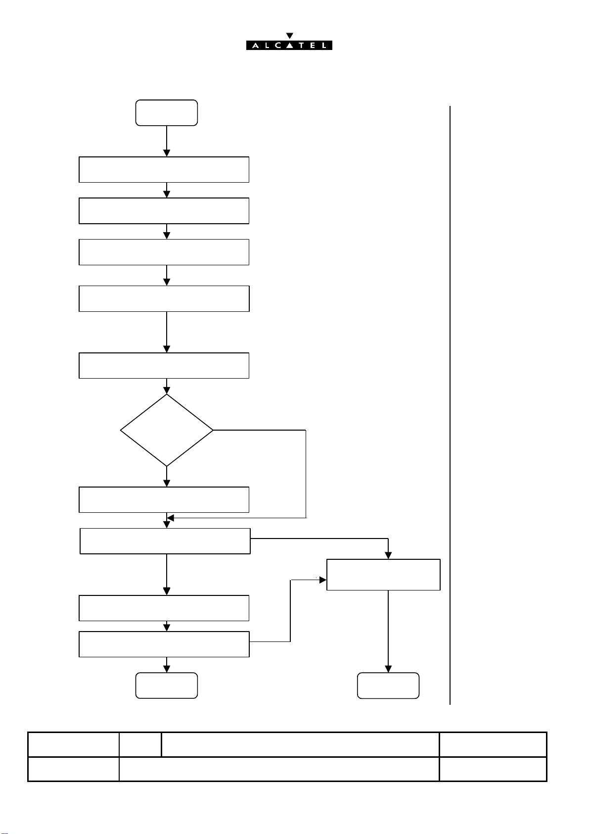
1) LEVEL 2 REPAIR PROCESS
start
Test + visual inspection
Disassembly
Hardware upgrading
Level 2 repair
Final assembly
Rear casing is
changed ?
N0
See § 2
See § 3
See § 4
See § 5
See § 6
YES
Complete sticker printing
Customization software downloading
OK
NOK
To a Level 3 repair centre
Software technical level sticker
Final test
OK
end
ED 04 09/10/00 REPAIR DOCUMENTATION BE1 and BE3 Level 2 BE 1/BE3
NOK
end
See § 7
See § 8
See § 7
See § 9
3/46
All rights reserved.Passing on and copying of this document, use and communication of its contents are not permitted without
authorization
Page 4
2) TEST & VISUAL INSPECTION
ALL these verifications must be done on ALL products coming back
in a LEVEL 2 after sales repair centre .
a) Check the aspect of the rear casing and the antenna
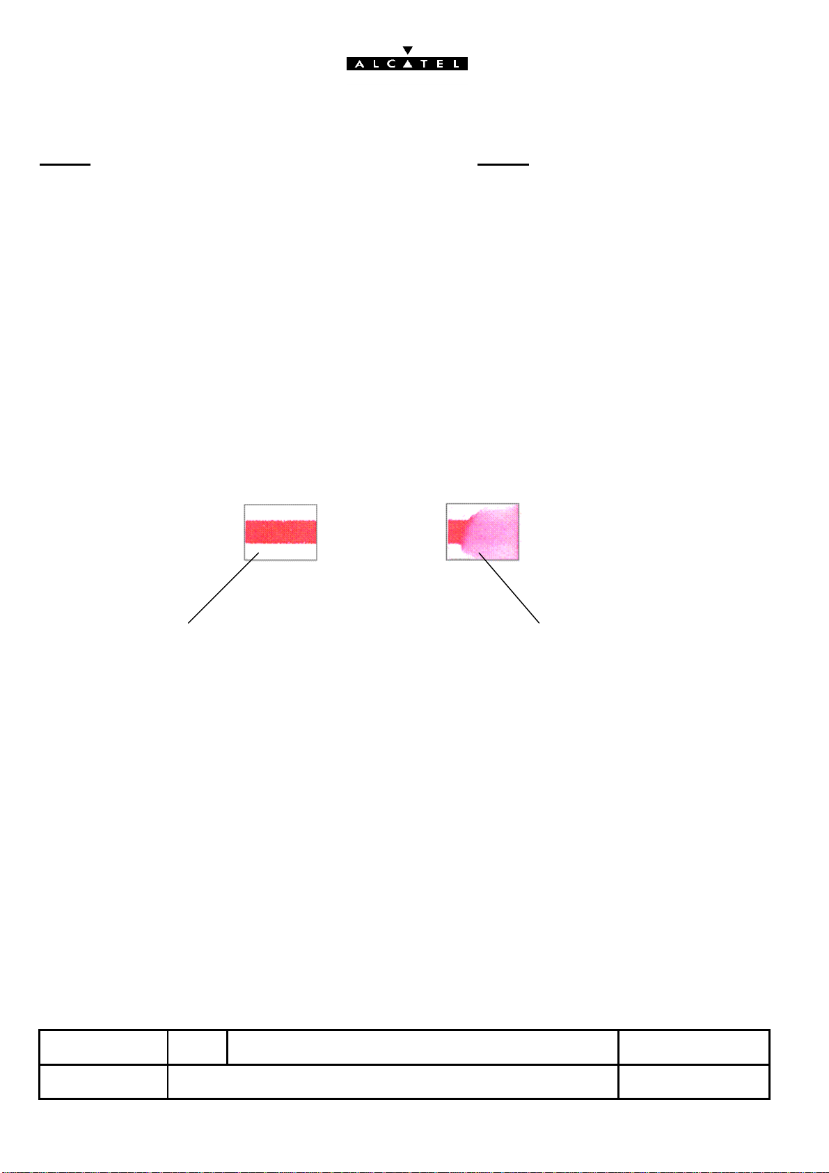
b) Humidity sticker : a humidity sticker is present on some
BE1 terminals on the shielding that can be seen on the rear
casing side, without openning the handset . Check the state of
the sticker as shown below :
Sticker of a good terminal Sticker of a terminal dived in water
This terminal is out of the warranty
c) Check J904 , the charge connector (corrosion ,contacts)
d) Check the SIM latch right functioning
e) Insert a SIM card and check the holding of the SIM latch
f) Plug a good battery and switch on the handset : check the
charging icon animation on the display, check the holding of
the product on the desk top charger.
ED 04 09/10/00 REPAIR DOCUMENTATION BE1 and BE3 Level 2 BE 1/BE3
4/46
All rights reserved.Passing on and copying of this document, use and communication of its contents are not permitted without
authorization
Page 5
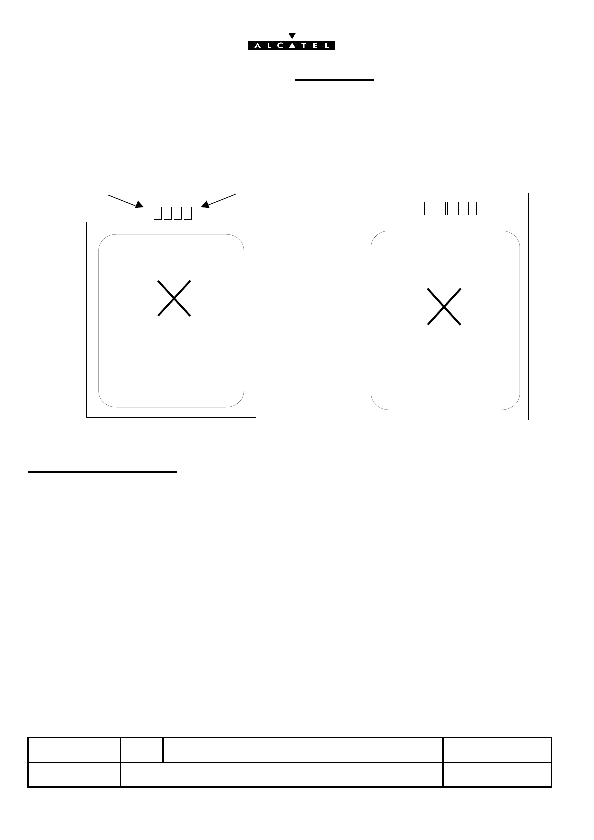
g) When the handset with its battery comes back to be
1
repaired, you must measure the voltage and the Thermistor
value as shown below.
2 3 4 5
NI MH Battery Lithium battery
With a multimeter:
6
ASSEMBLED IN FRANCE
POWER PACK
ALCATEL
1 2 3 4 5 6
ASSEMBLED IN FRANCE
POWER PACK
ALCATEL
• Measure the voltage between pin 1 and pin 6 (if < 2.9 V, the battery
is NOK)
• Measure the Thermistor value between pin 5 and pin 6 for Ni MH
battery
• Measure the Thermistor value between pin 4 and pin 6 for Lithium
battery (the Thermistor value must be 100 k? at 25 °C)
ED 04 09/10/00 REPAIR DOCUMENTATION BE1 and BE3 Level 2 BE 1/BE3
5/46
All rights reserved.Passing on and copying of this document, use and communication of its contents are not permitted without
authorization
Page 6
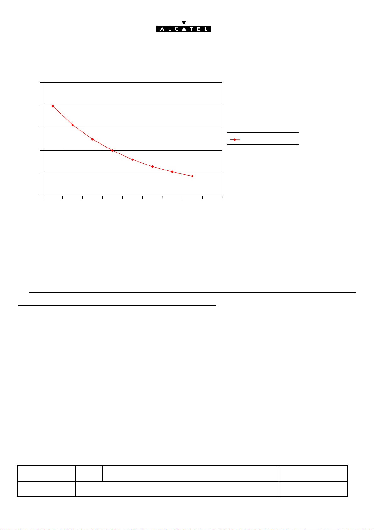
Resistor value/ temperature
050100
150
200
250
10152025303540
45
Thermistor
k
O
Temperature (°C)
If these measurements are NOK, the battery is swapped and
returned to Pilot Repair Centre of Laval.
If these measurements are OK : plug the battery on a good
handset, put it on a charger and check the charge icon
animation.
ED 04 09/10/00 REPAIR DOCUMENTATION BE1 and BE3 Level 2 BE 1/BE3
6/46
All rights reserved.Passing on and copying of this document, use and communication of its contents are not permitted without
authorization
Page 7

h) Switch on the handset and check the right functioning of
the keyboard and the volume keys ; check the display
backlighting
i) Switch off the product
j) Test the date and hour function
Plug a dummy battery (ref : SAVBE10004) on a 3,8v
power supply , switch on the handset , adjust the date and
hour , switch off the product and wait for 10 seconds .
Switch on the handset again , if the product asks for
the date and hour , the handset must be sent to a
LEVEL 3 repair centre.
ED 04 09/10/00 REPAIR DOCUMENTATION BE1 and BE3 Level 2 BE 1/BE3
7/46
All rights reserved.Passing on and copying of this document, use and communication of its contents are not permitted without
authorization
Page 8
All rights reserved. Passing on and copying of this
document, use and communication of its contents
not permitted without written authorization.
Ref:
ED
Dir:/data/RAFT/DATA_ALCATEL/doc/
05/10/2000
00000
D00
REPAIR DOCUMENTATION L
MULTI-PRODUIT
8 / 46
BE1/BE3
Page 9
All rights reserved. Passing on and copying of this
document, use and communication of its contents
not permitted without written authorization.
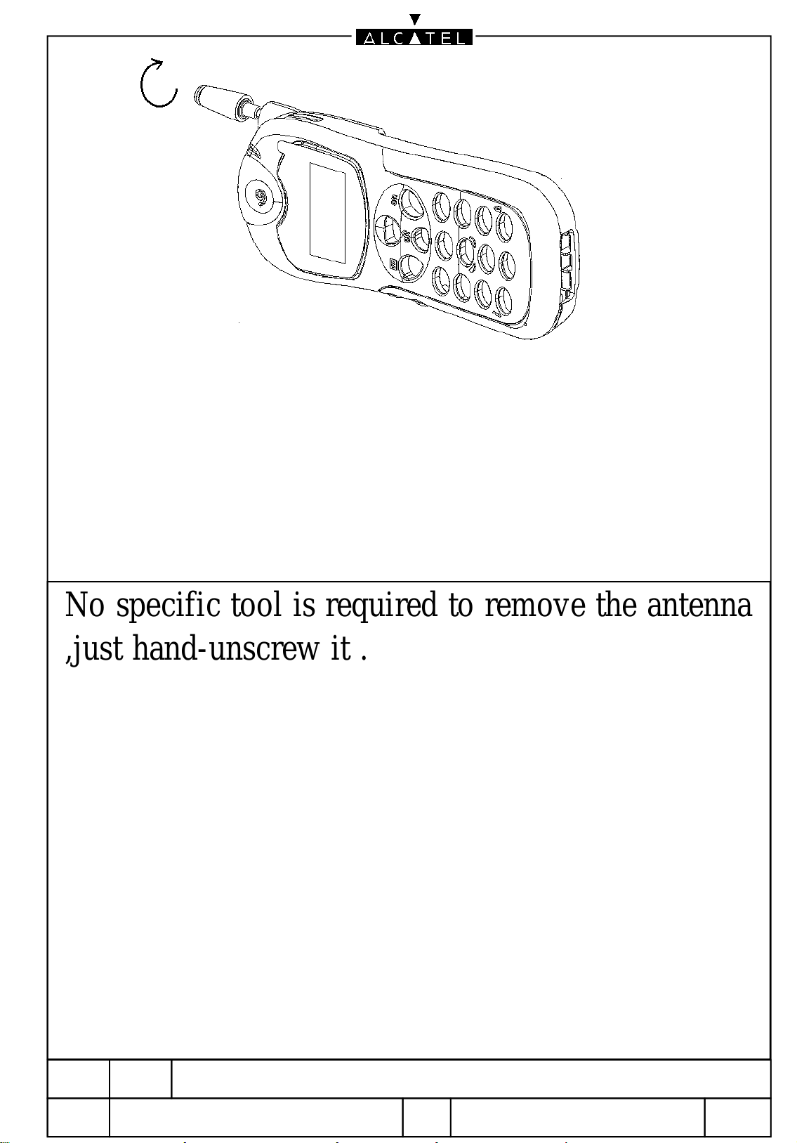
No specific tool is required to remove the antenna
,just hand-unscrew it .
Ref:
ED
Dir:/data/RAFT/DATA_ALCATEL/doc/
05/10/2000
00000
D00
REPAIR DOCUMENTATION L
MULTI-PRODUIT
9 / 46
BE1/BE3
Page 10
All rights reserved. Passing on and copying of this
document, use and communication of its contents
not permitted without written authorization.
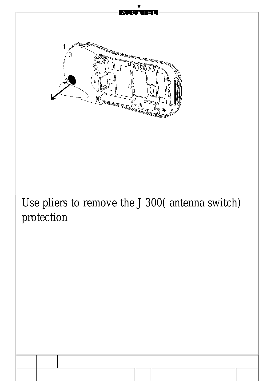
Use pliers to remove the J 300( antenna switch)
protection
Ref:
ED
Dir:/data/RAFT/DATA_ALCATEL/doc/
05/10/2000
00000
D00
REPAIR DOCUMENTATION L
MULTI-PRODUIT
10 / 46
BE1/BE3
Page 11
All rights reserved. Passing on and copying of this
document, use and communication of its contents
not permitted without written authorization.
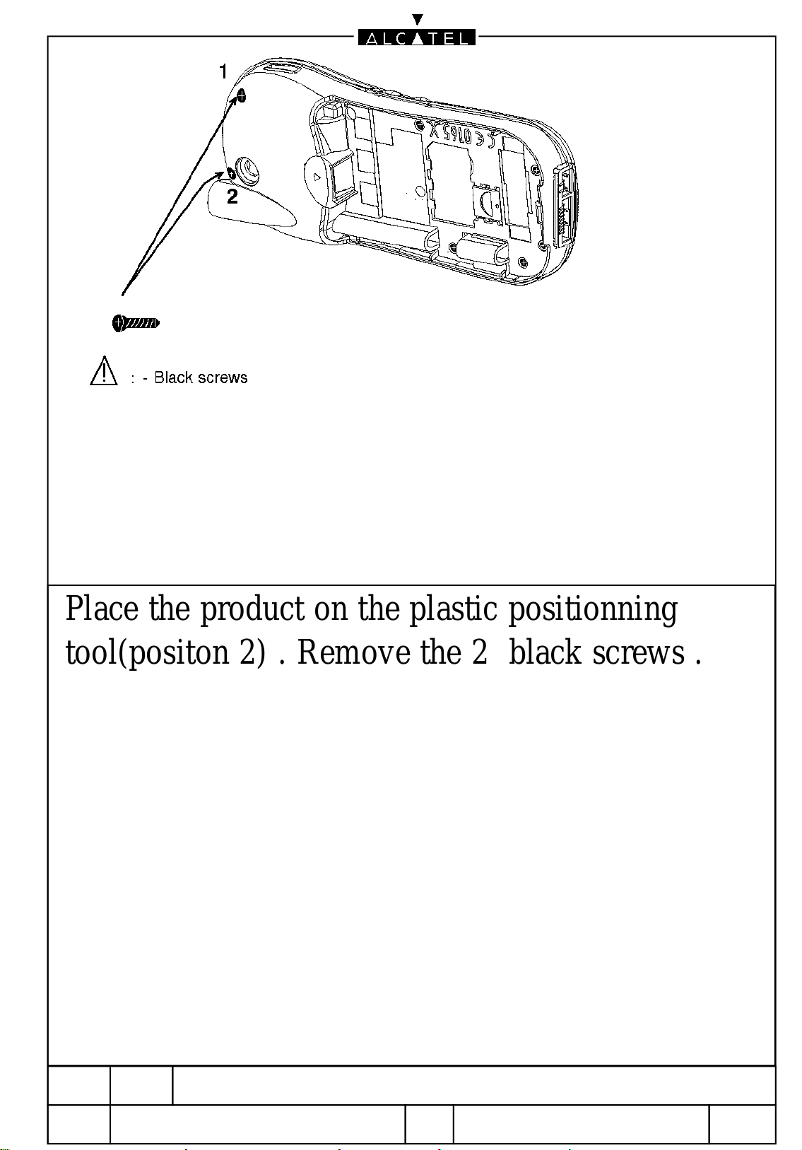
Place the product on the plastic positionning
tool(positon 2) . Remove the 2 black screws .
Ref:
ED
Dir:/data/RAFT/DATA_ALCATEL/doc/
05/10/2000
00000
D00
REPAIR DOCUMENTATION L
MULTI-PRODUIT
11 / 46
BE1/BE3
Page 12
All rights reserved. Passing on and copying of this
document, use and communication of its contents
not permitted without written authorization.
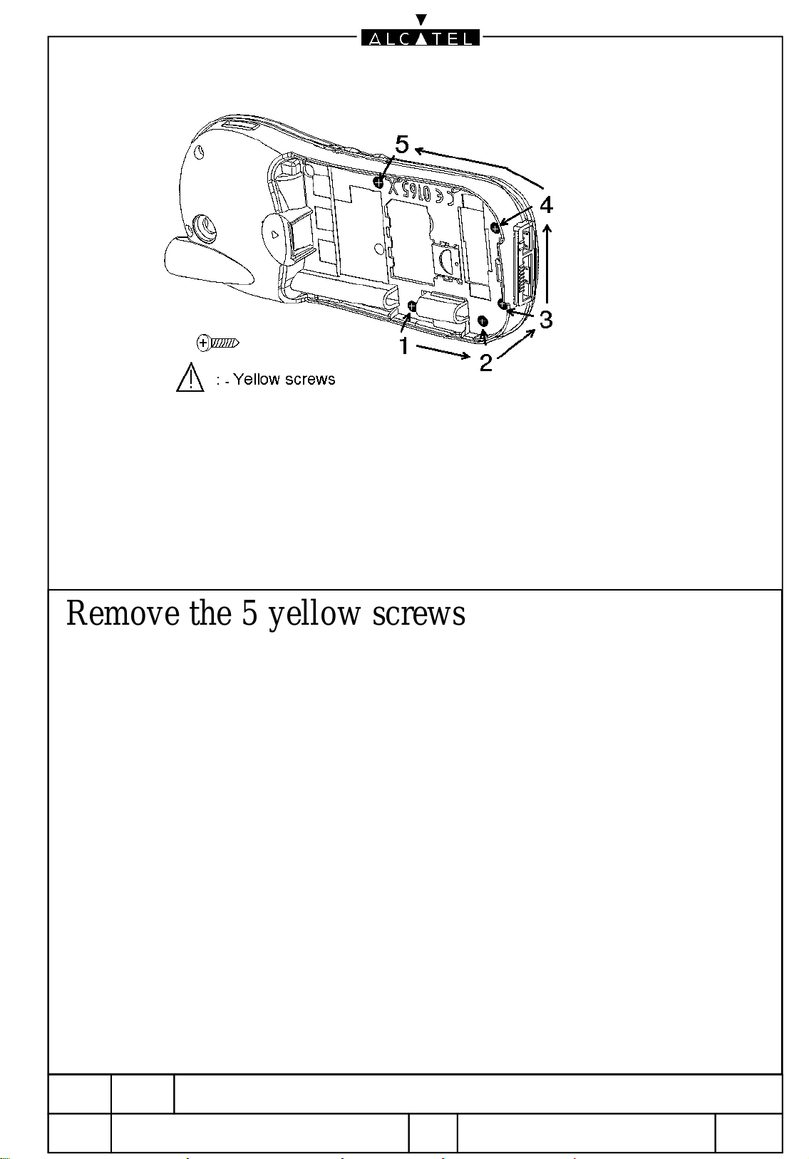
Remove the 5 yellow screws
Ref:
ED
Dir:/data/RAFT/DATA_ALCATEL/doc/
05/10/2000
00000
D00
REPAIR DOCUMENTATION L
MULTI-PRODUIT
12 / 46
BE1/BE3
Page 13
All rights reserved. Passing on and copying of this
document, use and communication of its contents
not permitted without written authorization.
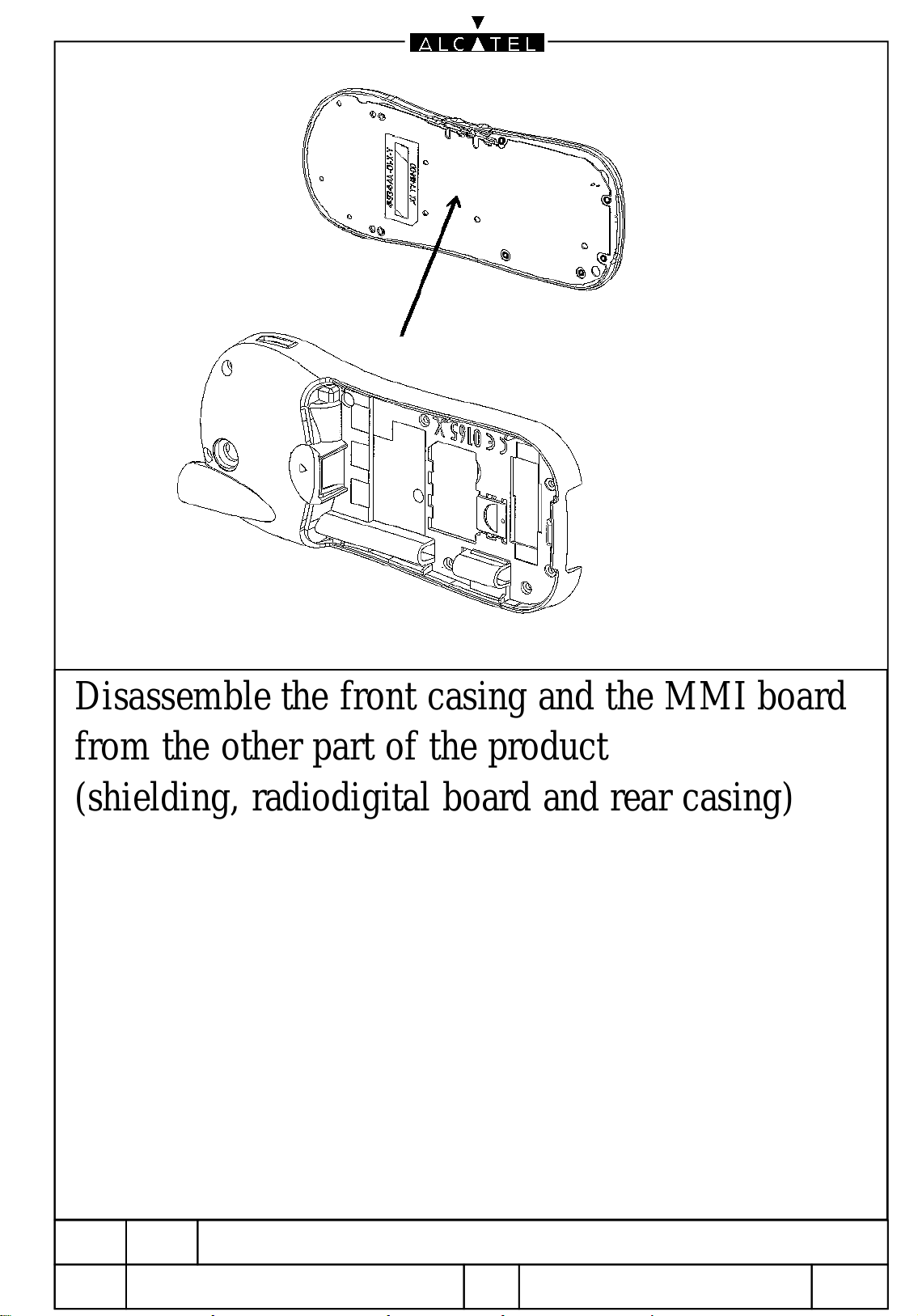
Disassemble the front casing and the MMI board
from the other part of the product
(shielding, radiodigital board and rear casing)
Ref:
ED
Dir:/data/RAFT/DATA_ALCATEL/doc/
05/10/2000
00000
D00
REPAIR DOCUMENTATION L
MULTI-PRODUIT
13 / 46
BE1/BE3
Page 14
All rights reserved. Passing on and copying of this
document, use and communication of its contents
not permitted without written authorization.
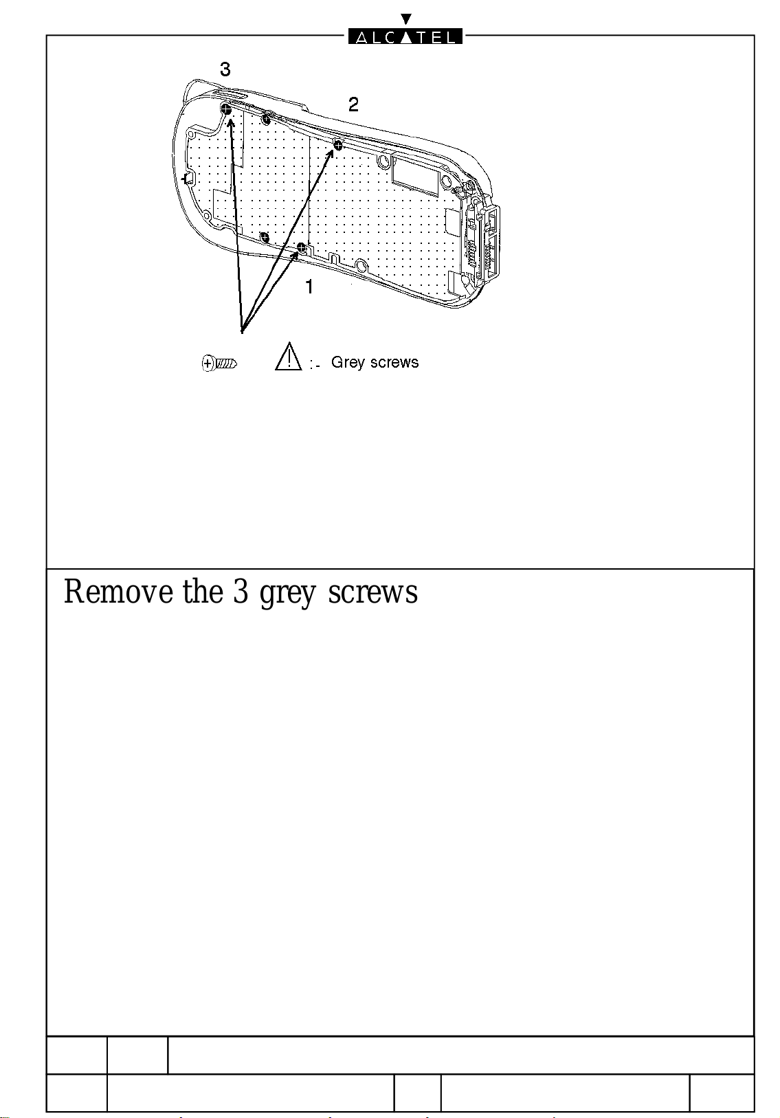
Remove the 3 grey screws
Ref:
ED
Dir:/data/RAFT/DATA_ALCATEL/doc/
05/10/2000
00000
D00
REPAIR DOCUMENTATION L
MULTI-PRODUIT
14 / 46
BE1/BE3
Page 15

All rights reserved. Passing on and copying of this
document, use and communication of its contents
not permitted without written authorization.
Remove the 2 white screws
Ref:
ED
Dir:/data/RAFT/DATA_ALCATEL/doc/
05/10/2000
00000
D00
REPAIR DOCUMENTATION L
MULTI-PRODUIT
15 / 46
BE1/BE3
Page 16

All rights reserved. Passing on and copying of this
document, use and communication of its contents
not permitted without written authorization.
Remove the upper shielding and check it.
Be aware of the positionning pin guide.
Ref:
ED
Dir:/data/RAFT/DATA_ALCATEL/doc/
05/10/2000
00000
D00
REPAIR DOCUMENTATION L
MULTI-PRODUIT
16 / 46
BE1/BE3
Page 17

All rights reserved. Passing on and copying of this
document, use and communication of its contents
not permitted without written authorization.
Remove the Radiodigital board and check it .
Be aware of the positionning pin guide .
Ref:
ED
Dir:/data/RAFT/DATA_ALCATEL/doc/
05/10/2000
00000
D00
REPAIR DOCUMENTATION L
MULTI-PRODUIT
17 / 46
BE1/BE3
Page 18

All rights reserved. Passing on and copying of this
document, use and communication of its contents
not permitted without written authorization.
Remove J 904 the charge connector , check its
mechanical state , if it is not OK change it .
Check the contacts of this connector on the main
board, if they are not OK clean them .
WARNING:
For all modifications and repair on radiodigital
board use the postionning tool ref : 17010061
it avoids the antenna contact damage (J 301)
Ref:
ED
Dir:/data/RAFT/DATA_ALCATEL/doc/
05/10/2000
00000
D00
REPAIR DOCUMENTATION L
MULTI-PRODUIT
18 / 46
BE1/BE3
Page 19

All rights reserved. Passing on and copying of this
document, use and communication of its contents
not permitted without written authorization.
Remove the lower shielding , check it , if it is not
OK change it .
Be aware of the positionning pin guide .
Check the mechanical state of the rear casing if
it is scratched change it .
Ref:
ED
Dir:/data/RAFT/DATA_ALCATEL/doc/
05/10/2000
00000
D00
REPAIR DOCUMENTATION L
MULTI-PRODUIT
19 / 46
BE1/BE3
Page 20

All rights reserved. Passing on and copying of this
document, use and communication of its contents
not permitted without written authorization.
Ref:
ED
Dir:/data/RAFT/DATA_ALCATEL/doc/
05/10/2000
00000
D00
REPAIR DOCUMENTATION L
MULTI-PRODUIT
20 / 46
BE1/BE3
Page 21

All rights reserved. Passing on and copying of this
document, use and communication of its contents
not permitted without written authorization.
Ref:
ED
Dir:/data/RAFT/DATA_ALCATEL/doc/
05/10/2000
00000
D00
REPAIR DOCUMENTATION L
MULTI-PRODUIT
21 / 46
BE1/BE3
Page 22

All rights reserved. Passing on and copying of this
document, use and communication of its contents
not permitted without written authorization.
Ref:
ED
Dir:/data/RAFT/DATA_ALCATEL/doc/
05/10/2000
00000
D00
REPAIR DOCUMENTATION L
MULTI-PRODUIT
22 / 46
BE1/BE3
Page 23

All rights reserved. Passing on and copying of this
document, use and communication of its contents
not permitted without written authorization.
Ref:
ED
Dir:/data/RAFT/DATA_ALCATEL/doc/
05/10/2000
00000
D00
REPAIR DOCUMENTATION L
MULTI-PRODUIT
23 / 46
BE1/BE3
Page 24

5)
REPAIRS
This describes the LEVEL 2 repairs that can be done without any diagnosys
equipment
ED 04 09/10/00 REPAIR DOCUMENTATION BE1 and BE3 Level 2 BE 1/BE3
24/46
All rights reserved.Passing on and copying of this document, use and communication of its contents are not permitted without
authorization
Page 25

Problem description actions & solutions
Rear casing It is scratched or broken Change it
Check the SIM connector (J902)
SIM reader
failure
Switch on with
battery power If there is no switch on
Display
failure
Keyboard and
backlighting
« CHECK SIM » error
Missing lines or columns or
no display
No keypad and/or display
backlighting
or
the keys don’t work
If it is faulty change it
Check battery contacts on the rear casing
Check the interboard connector (J905)
Check the MMI board
Try a software update
Change the faulty element
Check the MMI board
Check the interboard connector (J905)
Change the faulty element
Check the inter board connector (J905)
Check the MMI board
Change the faulty element
Antenna It is scratched or broken Change it
Network
Audio problems
the handset does not lock
properly on the network
or
radio problems
Bad or no reception
Bad or no emission
Handsfree problem
Check J 300, the RF contact
Check the metal part of the antenna
Change the faulty element
Check that the earpiece is not cut or its contacts are not
bent
Check J 905, the interboard connector
Check the MMI board
Check the MMI board (microphone)
Check J 905, the interboard connector
Check J 904, the rear connector
Change the faulty element
ED 04 09/10/00 REPAIR DOCUMENTATION BE1 and BE3 Level 2 BE 1/BE3
25/46
All rights reserved.Passing on and copying of this document, use and communication of its contents are not permitted without
authorization
Page 26

In case the LEVEL 2 repairs do not solve the problems, or if the radio
digital board is damaged, a LEVEL 3 repair is needed.
CAUTION
Before sending the products to a LEVEL 3 repair centre, make sure that you
have done every hardware upgrading.
ED 04 09/10/00 REPAIR DOCUMENTATION BE1 and BE3 Level 2 BE 1/BE3
26/46
All rights reserved.Passing on and copying of this document, use and communication of its contents are not permitted without
authorization
Page 27

All rights reserved. Passing on and copying of this
document, use and communication of its contents
not permitted without written authorization.
Ref:
ED
Dir:/data/RAFT/DATA_ALCATEL/doc/
05/10/2000
00000
D00
REPAIR DOCUMENTATION L
MULTI-PRODUIT
27 / 46
BE1/BE3
Page 28

All rights reserved. Passing on and copying of this
document, use and communication of its contents
not permitted without written authorization.
Place the rear casing on the plastic positionning
tool ( position1 )
Place the lower shielding in the rear casing .
Be aware of the positionning pin guide .
Ref:
ED
Dir:/data/RAFT/DATA_ALCATEL/doc/
05/10/2000
00000
D00
REPAIR DOCUMENTATION L
MULTI-PRODUIT
28 / 46
BE1/BE3
Page 29

All rights reserved. Passing on and copying of this
document, use and communication of its contents
not permitted without written authorization.
Place the radiodigital board in the lower shielding.
Be aware of J 904 , J 301 , and the positionning
pin guide .
Ref:
ED
Dir:/data/RAFT/DATA_ALCATEL/doc/
05/10/2000
00000
D00
REPAIR DOCUMENTATION L
MULTI-PRODUIT
29 / 46
BE1/BE3
Page 30

All rights reserved. Passing on and copying of this
document, use and communication of its contents
not permitted without written authorization.
Place the upper shielding .
Be aware of the positionning pin guide .
Ref:
ED
Dir:/data/RAFT/DATA_ALCATEL/doc/
05/10/2000
00000
D00
REPAIR DOCUMENTATION L
MULTI-PRODUIT
30 / 46
BE1/BE3
Page 31

All rights reserved. Passing on and copying of this
document, use and communication of its contents
not permitted without written authorization.
Place the upper shielding with 2 white screws ;
shift the shielding towards J 904 .
Ref:
ED
Dir:/data/RAFT/DATA_ALCATEL/doc/
05/10/2000
00000
D00
REPAIR DOCUMENTATION L
MULTI-PRODUIT
31 / 46
BE1/BE3
Page 32

All rights reserved. Passing on and copying of this
document, use and communication of its contents
not permitted without written authorization.
Screw the 3 grey screws ; respect the order of
screwing as shown as above
Ref:
ED
Dir:/data/RAFT/DATA_ALCATEL/doc/
05/10/2000
00000
D00
REPAIR DOCUMENTATION L
MULTI-PRODUIT
32 / 46
BE1/BE3
Page 33

All rights reserved. Passing on and copying of this
document, use and communication of its contents
not permitted without written authorization.
Ionize the MMI board ; be aware of the display
Ref:
ED
Dir:/data/RAFT/DATA_ALCATEL/doc/
05/10/2000
00000
D00
REPAIR DOCUMENTATION L
MULTI-PRODUIT
33 / 46
BE1/BE3
Page 34

All rights reserved. Passing on and copying of this
document, use and communication of its contents
not permitted without written authorization.
Place the front casing on the plastic positionning
tool ( position 2 ) .
Be aware there is no dust on the glass of the front
casing : ionize it .
Assemble the MMI board with the front casing +
keypad .
Be aware of the earpiece contacts .
Ref:
ED
Dir:/data/RAFT/DATA_ALCATEL/doc/
05/10/2000
00000
D00
REPAIR DOCUMENTATION L
MULTI-PRODUIT
34 / 46
BE1/BE3
Page 35

All rights reserved. Passing on and copying of this
document, use and communication of its contents
not permitted without written authorization.
Assemble the rear casing + the radiodigital board
to the MMI board + keypad .
be aware of the good position of the volume keys .
Ref:
ED
Dir:/data/RAFT/DATA_ALCATEL/doc/
05/10/2000
00000
D00
REPAIR DOCUMENTATION L
MULTI-PRODUIT
35 / 46
BE1/BE3
Page 36

All rights reserved. Passing on and copying of this
document, use and communication of its contents
not permitted without written authorization.
Place the yellow screws ; respect the order of
screwing as shown above .
Ref:
ED
Dir:/data/RAFT/DATA_ALCATEL/doc/
05/10/2000
00000
D00
REPAIR DOCUMENTATION L
MULTI-PRODUIT
36 / 46
BE1/BE3
Page 37

All rights reserved. Passing on and copying of this
document, use and communication of its contents
not permitted without written authorization.
Place the 2 black screws .
Ref:
ED
Dir:/data/RAFT/DATA_ALCATEL/doc/
05/10/2000
00000
D00
REPAIR DOCUMENTATION L
MULTI-PRODUIT
37 / 46
BE1/BE3
Page 38

All rights reserved. Passing on and copying of this
document, use and communication of its contents
not permitted without written authorization.
Screw the antenna as shown above .
Check the SWITCH ON of the handset .
Ref:
ED
Dir:/data/RAFT/DATA_ALCATEL/doc/
05/10/2000
00000
D00
REPAIR DOCUMENTATION L
MULTI-PRODUIT
38 / 46
BE1/BE3
Page 39

7) STICKERS
7.1)Rear casing sticker
Find below the specification concerning the stickers for BE 1 product , the file associated is developped with the
software CODESOFT and created on printer ZEBRA SPRITE 500 203 DPI .
The name of the file is IMEI_BE.LAB
This sticker must be printed when the rear casing has been changed .
11
2
7
1
3
8
6
5
4
10
Position
N°
1
Name
Code
(mm)
19.25 7.30 0 6x6 Variable 50 max DATAMATRIX
DATAMATRIX
2
Product Type 17.00 13.36 180 - 20 max “ type ”Helvetica PROD
3
Distributeur 13.40 13.36 180 - 40 max “ type ”Helvetica DISTRIB
4
Commercial
17.00 8.20 180 - 15 alpha “ type ”Helvetica REFCOM
Positio
x
n Y
(mm)
Orient. Heigh
(code
Barres
)
Nb and type for
caracters
Police / code Variable
ratio 3
Référence
5
Texte
17.00 11.70 180 - - “ type ”Helvetica -
“ Made in
Europe ”
6
Hardware
17.00 9.90 180 - 2 “ type ”Helvetica PTH
technical level
7
Software
13.00 9.90 180 - 2 “ type ”Helvetica PTS
technical level
8
9
10
11
Date Code 9.00 9.92 180 - 3 alpha “ type ”Helvetica DC
IMEI (number) 17.40 6.00 180 - 15 num “ type ”Helvetica IMEI15
IMEI (bar code) 2.20 0.55 0 3,5 15 num 128 ratio 2 IMEI15
Vibrator
180 Logo
Compatibility
9
DM
Content of DATAMATRIX code :
IMEI/Industrial reference/Hardware tech. level/Software tech. level/Commercial reference
If the 2D bar code is not readable , you can enter the references manualy
For this , use the file named : BE_SAV enter the references in the fields and for
the commercial reference type :3DS-SAV .
ED 04 09/10/00 REPAIR DOCUMENTATION BE1 and BE3 Level 2 BE 1/BE3
39/46
All rights reserved.Passing on and copying of this document, use and communication of its contents are not permitted without
authorization
Page 40

7.2) Software Technical Level sticker
When the rear casing has not been changed , it is mandatory to upgrade the indication of the software technical level
on the handset , as the software has been upgraded (unless the upgrade software is the same as the previous software)
A sticker indicating the software technical level must be sticked on the rear casing :
Software technical Level
16A
ED 04 09/10/00 REPAIR DOCUMENTATION BE1 and BE3 Level 2 BE 1/BE3
40/46
All rights reserved.Passing on and copying of this document, use and communication of its contents are not permitted without
authorization
Page 41

8) CUSTOMIZATION SOFTWARE DOWNLOADING
8.1 Customization with an ACKSYS equipment
The customization software runs under WINDOWS 95
• For customization the interface box must be plugged in POSITION 2 on ACKSYS box
• Under the screen PROGRAM MANAGER click on TELE BE1 Exx_xx or TELE BE3 Exx_xx
• Read the DATAMATRIX
• Put the terminal on the interface (ref : 24003096 ) and validate by ENTER
• Wait for the message “ PASS ”*
See Data for customization on the “ BE1 or BE3 Software Documentation ”
*If the message is “ FAIL ” the terminal needs a LEVEL 3 repair
(1)
Content of DATAMATRIX code :
IMEI/Industrial reference/Hardware tech. level/Software tech. level/Commercial reference
(1)
code with the “ 2D scanner ”
8.2 Customization with an ELIOS equipment
See Elios documentation for the installation of the system.
The customization software runs under WINDOWS NT
• Click on OTR BE1 or OTR BE3
• Fill in the fields :
- enter the « Commercial Reference »
- enter any value for the « n° OPL » (e.g : 99)
- enter any value for the « n° OF » (e.g : 12)
- enter the quantity of the handstets to customize
• Click on « Lancer le lot »
• Click « oui » to confirm the customization
• Wait for the end of « Phase d’initialisation »
• Put the handset on the interface (the LED lights orange )
• Wait for the LED lights green *
See Data for customization on the “BE1 or BE3 Software Documentation ”
* if the LED lights red : an error message appears (e.g : a faulty code such as Z xxx)
9) FINAL TEST
The final test is divided into 2 parts : a functional part and a measurement part.
ED 04 09/10/00 REPAIR DOCUMENTATION BE1 and BE3 Level 2 BE 1/BE3
41/46
All rights reserved.Passing on and copying of this document, use and communication of its contents are not permitted without
authorization
Page 42

9.1 Functionnal test
During the functional test, the following points must be checked :
• Cosmetic aspect of the handset, the stickers state on the rear casing
• Switch on the handset
• Welcome message (see « BE1 or BE3 software documentation »)
• The display and keypad backlighting
• Functionning of all the keys(bip and display )
• Plug of a charger : right position of the charger, display of the charge indicator
• Place the protection cap of the RF connector (J 300)
9.2 Measurements
At least the following must be checked :
Measurements Channels Power levels Conditions
Connection Mobile 63* 9 Car kit
Call base from mobile 5* 9 Car kit
Power level measurements
Phase error measurements
RX level measurements
5*
5*
5*
5
5
5
Car kit
Car kit
Car kit
Power level measurements
Phase error measurements
RX Level measurement
Power level measurements
Phase error measurements
RX Level measurements
Power level measurements
Phase error measurements
RX Level measurements
Power level measurements
Phase error measurements
RX Level measurements
70*
70*
70*
120*
120*
120*
515*
515*
515*
880*
880*
880*
9
5
19
5
5
5
0
0
0
0
0
0
Car kit
Car kit
Car kit
Car kit
Car kit
Car kit
Car kit
Car kit
Car kit
Car kit
Car kit
Car kit
Audio test (GSM) 70* 9 Car kit
Hang up 70* 9 Car kit
Call mobile from base 700* 9 Radiated measurements
Power Level measurements 700* 0 Radiated measurements
Audio test (DCS) 700* 0 Radiated measurements
Audio test (GSM) 70* 5 Radiated measurements
Hang up 70* 9 Radiated measurements
*these values are given for indication,compatible low,middle and high channels have to be found
ED 04 09/10/00 REPAIR DOCUMENTATION BE1 and BE3 Level 2 BE 1/BE3
42/46
All rights reserved.Passing on and copying of this document, use and communication of its contents are not permitted without
authorization
Page 43

APPENDIX 1
FAULT CODES
ED 04 09/10/00 REPAIR DOCUMENTATION BE1 and BE3 Level 2 BE 1/BE3
43/46
All rights reserved.Passing on and copying of this document, use and communication of its contents are not permitted without
authorization
Page 44

FAULT CODES FOR HANDSET FAILURE DESCRIPTION
Code Description Comments
AFF
CLA
ECL
EST
MEC
SIM
VIB
ECH
RIN
DHO
LOC
MST
CHB
Display failure No displaying, missing lines or columns
Keyboard or TPA or
lateral keys failure
Lighting problem On keyboard or display
Cosmetic problems
Mechanical failure
SIM reader failure The product requests “check SIM”
Integrated vibrator
problem
Audio Bad audio in discrete mode or in integrated hands free, or in a car kit
Ringing + key beep
failure
Date / Hour problems The product asks for the date after a switch off without taking off the battery
Locked by customer The end-user has programmed something in the menus and thinks the product is
Switch On failure The handset does not switch ON, but the battery is OK
Battery charge failure The charge of the battery does not work correctly, but the battery is OK
The handset is functional, but the end-user sends the phone back to after sales for
aesthetic reasons (eg : defective housing at antenna connection, striped window)
The handset is non functional because of an external broken part (eg : battery
Pressing a key does not work or the sensation is not OK.
connector broken , rear connector damaged)
The ringing or beep sound is not OK
faulty (eg : product code, switch off after 10 minutes …)
BAT
OTO
NWK
RFM
RST
SLO
NFF
OXY
ED 04 09/10/00 REPAIR DOCUMENTATION BE1 and BE3 Level 2 BE 1/BE3
Battery failure if the handset is functional and the battery is NOK (eg short circuit on an element..)
Concerns only the handsets coming back with their battery
Autonomy problem The end user complains about autonomy problem, but the handset is functional
Network error failure Problem of RF connection in live network (name of the operator does not appear, or
network icon blinks…)
Radio measurement
failure
Auto switch off or Reset If the end user complains about auto switch off or reset, but nothing can be seen in
SIM Lock failure The product asks for “ NETWORK KEY ” when switched on
No Fault Found
Corrosion problem Only if corrosion is the cause of the return in after sale.
Concerns any measurements on a GSM tester
the repair process
44/46
All rights reserved.Passing on and copying of this document, use and communication of its contents are not permitted without
authorization
Page 45

APPENDIX 2
EQUIPMENT FOR LEVEL 2 REPAIR CENTRE
ED 04 09/10/00 REPAIR DOCUMENTATION BE1 and BE3 Level 2 BE 1/BE3
45/46
All rights reserved.Passing on and copying of this document, use and communication of its contents are not permitted without
authorization
Page 46

MANDATORY EQUIPMENT SUPPLIED BY ALCATEL
• Plastic positionning tool (for assembly / disassembly)
• Plastic positionning tool for radiodigital board
• Final test kit (charger, battery, 2 SIM test cards, car kit)
• Dummy battery (for DHO test)
• ACKSYS equipment (bench and interfaces)
• Dongle (used for downloading and customisation)
• Stickers
MANDATORY EQUIPMENT NOT SUPPLIED BY ALCATEL
• Table cover and wristlet for ESD protection
• Soldering iron (adjustable temperature)
• Hot air machine
• Solder
• Desoldering wick
• Electrical or manual dynamometric screw driver
• Ionizing air gun or cold air blower
• Binocular
• Printer (2D bar code compatible)
• 2D bar code reader (with the cable which allows to plug the reader and the keyboard
in parallel)
• GO/NOGO tester
• Computer for ACKSYS equipment
• Software for stickers printing
ED 04 09/10/00 REPAIR DOCUMENTATION BE1 and BE3 Level 2 BE 1/BE3
46/46
All rights reserved.Passing on and copying of this document, use and communication of its contents are not permitted without
authorization
 Loading...