

Page 1

Alcatel-Lucent
8950 AAA (Authorization, Authentication, Accounting)
User’s Guide | Release 6.0
365-360-001R6.0
DEC 2008
ISSUE 1
Page 2

Alcatel, Lucent, Alcatel-Lucent and the Alcatel-Lucent logo are trademarks of Alcatel-Lucent. All other trademarks are the property of their respective owners..
The information presented is subject to change without notice. Alcatel-Lucent assumes no responsibility for inaccuracies contained herein.
Copyright © 2008 Alcatel-Lucent. All Rights Reserved.
Page 3

Contents
About this information product
Where to go First .......................................................................................................................................1-ii
How This Manual Is Organized ...............................................................................................................1-iii
Conventions ..............................................................................................................................................1-vi
Recommended Reading ...........................................................................................................................1-vii
Obtaining Technical Support ...................................................................................................................1-vii
Part 1: Configuration Tools Navigation Pane
1 Introduction to 8950 AAA
What is 8950 AAA? ..................................................................................................................................1-1
RADIUS Terms Explained ........................................................................................................................1-3
2 8950 AAA Server Management Tool Overview
Purpose of the Server Management Tool ..................................................................................................2-1
Starting the Server Management Tool .......................................................................................................2-2
The Server Management Tool User Interface ...........................................................................................2-4
3 Server Management Tool Command Set
SMT menus and their commands ..............................................................................................................3-1
Managing Data in SMT Panels ...............................................................................................................3-11
Sizing Table Columns .............................................................................................................................3-13
Installing the PolicyAssistant and the Policy Flow Editor ...................... ..... ...........................................3-13
4 Managing 8950 AAA Servers
Configuring Server Properties ...................................................................................................................4-1
Policy Server tab .......................................................................................................................................4-2
Universal State Server tab .......................................................................................................................4-28
Configuration Server tab ................................................................ ..... ....................................................4-38
5 Configuring 8950 AAA Client Properties
Introduction ...............................................................................................................................................5-1
Configuring Clients ...................................................................................................................................5-2
The Radius Clients tab ..............................................................................................................................5-4
............................................................................................................................................................................................................................................................
365-360-001R6.0
Issue 1 December 2008
iii
Page 4

Contents
............................................................................................................................................................................................................................................................
The Diameter Peers tab ...................................................................................... .... ..... .............................. 5-8
The TACACS+ Clients tab ...................................................................................................................... 5-11
The Client Classes tab ............................................................................................................................. 5-14
6 Configuring 8950 AAA Realm Routing Table Properties
Configuring Realm Routing Table ............................................................................................................ 6-1
7 Configuring 8950 AAA Remotely
Remote Configuration ............................................................................................................................... 7-1
8 Using the 8950 AAA Policy Flow Editor
Policy Flow Editor .................................................................................................................................... 8-1
Policy Flow Files ....................................................................................................................................... 8-3
Method Configuration ............................................................................................................................... 8-4
Method Dispatch Section .......................................................................................................................... 8-9
9 Using the 8950 AAA Policy Assistant in Server Management Tool
Understanding PolicyFlow, the PolicyAssistant, and the Policy Wizard ..................................................9-2
Installing the PolicyAssistant ............................................................................................... ..................... 9-2
Preparing to Create Your First Policy ....................................................................................................... 9-3
Using the Policy Wizard ........................................................................................................................... 9-4
Understanding and Creating Attribute Sets ............................................................................................ 9-16
Adding Attribute Sets to Your Policy ...................................................................................................... 9-19
Creating Attribute Sets ............................................................................................................................ 9-20
Defining a Failure Mode ......................................................................................................................... 9-23
Reviewing Your Policy ............................................................................................................................ 9-25
Using the PolicyAssistant ........................................................................................................................ 9-25
Saving Your Policies ............................................................................................................................... 9-30
Advanced Authentication Options .......................................................................................................... 9-30
Advanced Attribute Set Options ............................................................................................................. 9-37
10 Configuring 8950 AAA USSv2
USSv2 Configuration .............................................................................................................................. 10-1
11 Configuring 8950 AAA Operators
Administering the 8950 AAA System .................................................................................................... 11-1
8950 AAA Operators Panel .................................................................................................................... 11-3
Adding an Operator ...............................................................................................................................11-11
............................................................................................................................................................................................................................................................
iv
365-360-001R6.0
Issue 1 December 2008
Page 5

Contents
............................................................................................................................................................................................................................................................
Adding an Access Rule .........................................................................................................................11-13
Modifying a System Operator ...............................................................................................................11-16
12 Configuring Simple Address Manager
Simple Address Manager Configuration .................................................................................................12-1
13 Configuring USS Address Manager
USS Address Manager Configuration .....................................................................................................13-1
Part II: Stats Collecting Navigation Pane
14 Stats Collector
The Stats Collector ................................................... .... .................................................... .......................14-1
Stats Collector Panel ...............................................................................................................................14-2
15 Configuring Reports
The Configure Reports Panel ....................................................................... ...........................................15-1
Part III: Logging Tools Navigation Pane
16 Message Logging
8950 AAA Message Overview ................................................................................................................ 16-1
Logging Tools ..........................................................................................................................................16-2
Server Log Messages ..............................................................................................................................16-3
Log Channels ...........................................................................................................................................16-6
Log Channel Configuration Panel Tabs ................................................................................................16-14
Notes on the Naming of Size Based Files .............................................................................................16-19
Notes on the Naming of Time Based Files ............................................................................................16-21
Log Rules ..............................................................................................................................................16-32
Part IV: Monitoring Tools Navigation Pane
17 Server Statistics
Monitoring Server Statistics ....................................................................................................................17-1
Server Statistics Panel .............................................................................................................................17-2
Sessions/ Counters/ Indices Panel .........................................................................................................17-28
USS Address Statistics Panel ........................................................................... ..... ................................17-31
18 Using LiveAdministrator
8950 AAA LiveAdministrator .................................................................................................................18-2
Accessing the LiveAdministrator Panel ..................................................................................................18-2
............................................................................................................................................................................................................................................................
365-360-001R6.0
Issue 1 December 2008
v
Page 6

Contents
............................................................................................................................................................................................................................................................
General Info ............................................................................................................................................ 18-3
License Information ................................................................................................................................ 18-4
System Information ................................................................................................................................. 18-5
Garbage Collection ................................................................................................................................. 18-6
Files in Use .............................................................................................................................................. 18-8
Admin Scripts ......................................................................................................................................... 18-9
Properties .............................................................................................................................................. 18-10
Cache Entries ........................................................................................................................................ 18-11
Peer Control .......................................................................................................................................... 18-12
Advanced .............................................................................................................................................. 18-13
Part V: File Tools Navigation Pane
19 Creating and Managing User Profiles with Files
The User File ............................................................................... ............................................................ 19-2
The PolicyAssistant and User Files ...................................................................................... ................... 19-2
The SMT User Files Panel ...................................................................................................................... 19-3
Creating an Attribute Set File ............................................................................................................... 19-16
20 8950 AAA Dictionary Editor
Accessing the Dictionary Editor Panel ................................................................................................... 20-1
Vendors Tab ............................................................................................................................................. 20-2
Attributes Tab ............................................................................................ .............................................. 20-4
Diameter Applications Tab ..................................................................................................................... 20-9
21 Managing files
The File Manager Panel .......................................................................................................................... 21-1
Tail panel ............................................................................................................................................... 21-10
22 8950 AAA Certificate Manager
Types of Certificates ........................................ ....................................................................................... 22-1
The Certificate Manager Panel .................................. ..... ...................................................... ................... 22-2
Requirements for Using the Certificate Manager ................................................................................... 22-8
Types of Certificates in Certificate Manager .......................................................................................... 22-9
Procedures for Creating Certificates ..................................................................................................... 22-18
Notes on Using Certificates .................................................................................................................. 22-20
How to Configure for a TLS Demo Out of the Box ............................................................................. 22-21
............................................................................................................................................................................................................................................................
vi
365-360-001R6.0
Issue 1 December 2008
Page 7

Contents
............................................................................................................................................................................................................................................................
Part VI: Database Tools Navigation Pane
23 Creating and Managing User Profiles with the Built-in Database
Understanding Database Users ................................................................................................................23-1
Logging in to the Database ......................................................................................................................23-2
Creating and Managing User Profiles .....................................................................................................23-3
Understanding Database SQL Tool .......................................................................................................23-19
Managing Hypersonic Database Users .................................................................................................23-22
Part VII: Other chapters
24 Server Diagnostics and Control Commands
Server Diagnostics and Control ...............................................................................................................24-1
List of Server Commands ........................................................................................................................24-2
Part VIII: Appendix
A Supplementary Information
Displaying the Built-in Web Interface ...................................................................................................... A-1
Displaying the RADIUS Server Administration Interface .......................................................................A-2
Displaying the Configuration Server Administration Interface ............................................................... A-3
GL Glossary
IN Index
............................................................................................................................................................................................................................................................
365-360-001R6.0
Issue 1 December 2008
vii
Page 8

Contents
............................................................................................................................................................................................................................................................
............................................................................................................................................................................................................................................................
viii
365-360-001R6.0
Issue 1 December 2008
Page 9

About this information
product
Overview
Purpose
Welcome, you are about to embark on a course to set up secure access to your network
with the industry’s leading RADIUS server, 8950 AAA. It provides you the highest level
of control and management of a wide range of access services. These services range from
simple dial-up remote access using Point-to-Point Protocol (PPP), Local Area Network
(LAN) access, wireless (Wi-Fi) and wired, and even access to core network elements such
as switches and routers.
RADIUS, or Remote Authentication Dial-In User Service, enables network operators to
authenticate, authorize and account (AAA) for users. The RADIUS protocol defines
communications between an access device or server and the RADIUS server. RADIUSbased security ensures that only users who meet your access criteria will be allowed access
to a resource. The 8950 AAA server provides this functionality within an extensible,
easy-to-use environment.
This manual introduces you to 8950 AAA through its friendly user interface, the Server
Management Tool (SMT) and its integrated polic y conf iguration tool, the PolicyAssistant.
These tools provide a simple way to conf igure 8950 AAA for the most common AAA
applications.
The PolicyAssistant creates, manages, and applies policies to control how and when users
access your network. A policy is a set of rules that 8950 AAA uses to determine ho w users
are authenticated, how access is authorized and configured, and how accounting data is
stored.
The PolicyAssistant can be conf igured to support as man y access policies as your netw ork
may require. You decide how many policies are necessary based on your business needs.
These needs can include the type of services your network provides, your equipment
requirements, your customers’ requirements, or the geographic location of your
customers.
............................................................................................................................................................................................................................................................
365-360-001R6.0
Issue 1, December 2008
i
Page 10
Where to go First
............................................................................................................................................................................................................................................................
Audience
This guide is designed to be used by qualified system administrators and network
managers. Knowledge of basic networking concepts is required to successfully install
8950 AAA. You should be familiar with RADIUS server installation, configuration, and
use.
Where to go First
How to Start
For more information about installing 8950 AAA and general software and hardware
requirements, read the 8950 AAA Quick Start Guide.
If you are new to 8950 AAA, the links below should help determine where to go first:
Ready to configure 8950 AAA?
With the Server Management Tool (SMT) running, you should see the Policy Flow Editor
in the Navigation pane as shown in Figure 1-1.
Figure 1-1 Server Management Tool-Navigation Screen
If you have already installed 8950 AAA and know how to launch the SMT, refer to the
section “Using the Policy Wizard” on 9-4 to begin configuring your RADIUS
environment.
............................................................................................................................................................................................................................................................
ii
365-360-001R6.0
Issue 1, December 2008
Page 11

How This Manual Is Organized
............................................................................................................................................................................................................................................................
Looking for the PolicyAssistant?
If you cannot find the PolicyAssistant in the Navigation pane when the Server
Management Tool is running, refer to the section “Installing the PolicyAssistant and the
Policy Flow Editor” on 3-13 to learn how to install the PolicyAssistant.
Attempting to start the Server Management Tool?
If you need help launching the Server Management Tool (SMT), refer to the section
“Preparing to Create Your First Policy” on 9-3 to learn more about the SMT.
What is RADIUS?
If you are new to the RADIUS world of access control, refer to “RADIUS Terms
Explained” on 1-3 to learn more about 8950 AAA and RADIUS terminology.
How This Manual Is Organized
Manual organization
This manual covers the steps necessary to set up your 8950 AAA server, clients, and user
profiles to process user requests for network access. The manual is organized as follows:
Chapter 1, “Introduction to 8950 AAA”
This section provides an introduction to 8950 AAA and some of the terms that you will
encounter when working with the 8950 AAA product.
Chapter 2, “8950 AAA Server Management Tool Overview”
This chapter covers the Server Management Tool layout and how to install the
PolicyAssistant.
Chapter 3, “Server Management Tool Command Set”
This chapter discusses the Server Management Tool commands that are accessible from
the menu bar, toolbar, and navigation pane of the user interface.
Chapter 4, “Managing 8950 AAA Servers”
This chapter addresses methods in controlling the behavior of 8950 AAA Servers.
Chapter 5, “Configuring 8950 AAA Client Properties”
This chapter discusses the process of configuring clients such as Network Access Servers
(NASs) or other access points with the 8950 AAA SMT.
............................................................................................................................................................................................................................................................
365-360-001R6.0
Issue 1, December 2008
iii
Page 12

How This Manual Is Organized
............................................................................................................................................................................................................................................................
Chapter 6, “Configuring 8950 AAA Realm Routing Table Properties”
This chapter discusses the process of configuring the Realm Routing Table.
Chapter 7, “Configuring 8950 AAA Remotely”
This chapter discusses the process of configuring the 8950 AAA remotely.
Chapter 8, “Using the 8950 AAA Policy Flow Editor”
This chapter discusses the process of configuring and creating necessary entities for the
Policy Flow Editor in the 8950 AAA Server Management Tool.
Chapter 9, “Using the 8950 AAA Policy Assistant in Server Management Tool”
This chapter discusses the process of how to use, configure, and create necessary entities
for the PolicyAssistant in the 8950 AAA Server Management Tool.
Chapter 10, “Configuring 8950 AAA USSv2”
This chapter discusses the process of configuring the 8950 AAA USSv2 functionality.
Chapter 11, “Configuring 8950 AAA Operators”
This chapter provides information about defining administrator access to 8950 AAA. It
defines different administrator roles and functions. It also provides information on how to
use the SMT Operators panel.
Chapter 12, “Configuring Simple Address Manager”
This chapter discusses the tools that are used for the configuration and management of
address pool by the Simple Address Manager . Simple Address Manager pro vides dynamic
address pool management.
Chapter 13, “Configuring USS Address Manager”
This chapter discusses the tools that are available for the conf iguration and management of
address pools of 8950 AAA, using Universal State server.
Chapter 14, “Stats Collector”
This chapter discusses about the various parts of 8950 AAA tool that collects statistical
information of 8950 AAA.
Chapter 15, “Configuring Reports”
This chapter discusses about the reports configurator for the 8950 AAA tool.
............................................................................................................................................................................................................................................................
iv
365-360-001R6.0
Issue 1, December 2008
Page 13

How This Manual Is Organized
............................................................................................................................................................................................................................................................
Chapter 16, “Message Logging”
This chapter discusses how to determine the information that is logged, the format for
logging it, and the destination for the logged information.
Chapter 17, “Server Statistics”
This chapter covers how to collect statistics for the 8950 AAA server.
Chapter 18, “Using LiveAdministrator”
This chapter discusses how to use the LiveAdministrator panel to manage, diagnose and
control the 8950 AAA server.
Chapter 19, “Creating and Managing User Profiles with Files”
This chapter covers how to create a user file and add and edit user profiles.
Chapter 20, “8950 AAA Dictionary Editor”
This chapter provides information about the 8950 AAA Data Dictionary and some of the
terms that you will encounter when working with the 8950 AAA product.
Chapter 21, “Managing files”
This chapter discusses 8950 AAA files and how to create and manage them using the File
manager panel.
Chapter 22, “8950 AAA Certificate Manager”
This chapter discusses the 8950 AAA Certificate Manager, also known as nrcert. Root
certificates generated with nrcert are self-signed certificates.
Chapter 23, “Creating and Managing User Profiles with the Built-in Database”
This chapter discusses how to manage user profiles stored in a Structured Query Language
(SQL) database, besides managing database users, administrators, and 8950 AAA tables.
Chapter 24, “Server Diagnostics and Control Commands”
This chapter describes the 8950 AAA server control commands.
Appendix A, “Supplementary Information”
The appendix contains examples of 6 SMT text files that are produced through SMT
activity.
............................................................................................................................................................................................................................................................
365-360-001R6.0
Issue 1, December 2008
v
Page 14

Conventions
............................................................................................................................................................................................................................................................
Conventions
Table 1-1 lists the typographical conventions used throughout this manual.
Table 1-1 Conventions used in the document or manual
Convention Meaning Example
boldface Names of items on screens.
Names of commands,
properties and plug-ins.
Names of buttons you should
click.
Arial boldface
Names of keys you should
press.
<angle brackets> Variables that require you to
substitute another value.
italics
Names of manuals or the first
occurrence of a glossary
term.
Arial italic
Directories, paths, file
names, email addresses, and
Uniform Resource Locators
(URLs).
Click the Enable check box.
The AuthLocal plug-in
compares password attributes.
Click Validate to check the
syntax of the method.
Press Enter to continue.
http://<server IP address or
name>
where <server IP address or
name> is the address of name
of the
8950 AAA server.
Refer to the 8950 AAA 6.0
User’s Guide and
Reference for more
information.
The 8950 AAA Web site is
http://www.8950AAA.com
click Press the left mouse button
once.
To view the online help, click
the book icon on the
8950
AAA toolbar.
right-click Press the right mouse button
once.
double-click Press the left mouse button
twice.
............................................................................................................................................................................................................................................................
vi
Right-click a Selector T ype to
view a list of selector types
for method selection.
To open the Accounting
Method Configuration panel,
double-click anywhere on the
tab display.
365-360-001R6.0
Issue 1, December 2008
Page 15

Recommended Reading
............................................................................................................................................................................................................................................................
Recommended Reading
Reference reading
The following books cover a variety of topics that you might encounter while working
with 8950 AAA. These books provide more information on the vast number of protocols
and applications that 8950 AAA supports.
Building Internet Firewalls (2nd ed.). Elizabeth D. Zwicky, Simon Cooper, D. Brent
Chapman, and Deborah Russell. O'Reilly & Associates, Inc., 2000. (ISBN 1-56592-871-
7)
Firewalls and Internet Security: Repelling the Wily Hacker (2nd ed.). William P.
Cheswick, Steven M. Bellovin, and Aviel D. Rubin. Addison-Wesley Publishing
Company, February, 2003. (ISBN 0-20163-466-X)
Internetworking with TCP/IP, Volume 1: Principles, Protocols, and Ar chitecture (4th ed.).
Douglas E. Comer. Pearson Education, February, 2000. (ISBN 0-13018-380-6)
Mastering Regular Expr essions (2nd ed.). Jef fre y E. F. Friedl. O'Reilly & Associates, Inc.,
July, 2002. (ISBN 0-59600-289-0)
RADIUS: Securing Public Access to Private Resources. Jonathan Hassell. O'Reilly &
Associates, Inc., October, 2002. (ISBN 0-596-00289-6)
The DHCP Handbook (2nd ed.). Ralph E. Droms and Ted Lemon. Pearson Education,
October 2002. (ISBN 0-67232-32 3)
Understanding PKI: Concepts, Standards, and Deployment Considerations (2nd ed.).
Carlisle Adams and Steve Lloyd. Pearson Education, May 2002. (ISBN 0-67232-391-5)
Understanding and Deploying LDAP Directory Services (2nd ed.). Timothy A. Howes,
Gordon S. Good, and Mark C. Smith. Addison-W esle y, May, 2003. (ISBN 1-67232-316-8)
UNIX in a Nutshell: A Desktop Quick Refer ence for SVR 4 and Solaris 7 (3rd ed.). Arnold
Robbins. O'Reilly & Associates, Inc., August, 1999. (ISBN 1-56592-42 4)
Obtaining Technical Support
Technical Support
To contact Alcatel-Lucent for technical support, select the support channel that applies to
you.
Support Channel 1: If you have purchased a 8950 AAA support contract, contact
Alcatel-Lucent World-Wide Services (LWS):
............................................................................................................................................................................................................................................................
365-360-001R6.0
Issue 1, December 2008
vii
Page 16

Obtaining Technical Support
............................................................................................................................................................................................................................................................
• Customers in the USA and Canada, call 1-866-LUCENT8, Prompt 3. If you are not
registered, use Prompt 7.
• Customers in other international locations, call +1-510-74 2000 or
+1-410-381-3484
• Alcatel-Lucent Customer Support Web Site: http://www.alcatel-lucent.com/support/
• Alcatel-Lucent Customer Support Web Site: http://support.lucent.com
Support Channel 2: If you have purchased 8950 AAA within the last 90 days, you can
contact Lucent Technologies World-Wide Services (LWS) for email support:
• Alcatel-Lucent Customer Support Web Site: http://support.lucent.com
Important! If you are a first time LWS support user OR if you have not yet
registered your 8950 AAA service contract, contact LWS.
Support Channel 3: If you are evaluating 8950 AAA for purchase or need sales
information or technical support (but do not have a support contract), contact us for:
• Technical support questions, review the 8950 AAA Discussion Forum:
http://www.8950AAA.com/cgi-bin/dcforum/dcboard.cgi
• Pre-sales product questions, send an email to: tech-sales@8950AAA.com
• Sales information, send an email to sales@8950AAA.com
• Queries from Alcatel-Lucent employees, Sales Teams, VARS and Resellers, send an
• Other non-technical requests, send an email to: tech-sales@8950AAA.com
How to Comment
To comment on this information product, Online(<http://www.lucent-info.com/comments>http://www.lucent-
info.com/comments/)
lucent.com.
email to: radius-internal@8950AAA.com
email your comments to the Comments Hotline: comments@alcatel-
............................................................................................................................................................................................................................................................
viii
365-360-001R6.0
Issue 1, December 2008
Page 17

Part 1: Configuration Tools
Navigation Pane
Overview
Purpose
This part consolidates the chapters related to Configuration Tools in the SMT Navigation
pane.
Contents
This part includes the following chapters.
Chapter 1, “Introduction to 8950 AAA” 1-1
Chapter 2, “8950 AAA Server Management Tool Overview” 2-1
Chapter 3, “Server Management Tool Command Set” 3-1
Chapter 4, “Managing 8950 AAA Servers” 4-1
Chapter 5, “Configuring 8950 AAA Client Properties” 5-1
Chapter 6, “Configuring 8950 AAA Realm Routing Table Properties” 6-1
Chapter 7, “Configuring 8950 AAA Remotely” 7-1
Chapter 8, “Using the 8950 AAA Policy Flow Editor” 8-1
Chapter 9, “Using the 8950 AAA Policy Assistant in Server Management Tool” 9-1
Chapter 10, “Configuring 8950 AAA USSv2” 10-1
Chapter 11, “Configuring 8950 AAA Operators” 11-1
Chapter 12, “Configuring Simple Address Manager” 12-1
Chapter 13, “Configuring USS Address Manager” 13-1
............................................................................................................................................................................................................................................................
365-360-001R6.0
Issue 1, December 2008
1-1
Page 18

............................................................................................................................................................................................................................................................
............................................................................................................................................................................................................................................................
1-2
365-360-001R6.0
Issue 1, December 2008
Page 19

1 Introduction to 8950
AAA
Overview
Purpose
This chapter provides an introduction to 8950 AAA and some of the terms that you will
encounter when working with the 8950 AAA product.
The following topics are included in this chapter:
What is 8950 AAA?
RADIUS Terms Explained
What is 8950 AAA?
Overview
8950 AAA is server software that is used to manage secure access to networks, servers,
and information services. Network elements that use a RADIUS server to manage access
are known as clients. An example of a RADIUS client might be a network access server
(NAS), a Wi-Fi access point, or even a Web page. 8950 AAA is a tool that promotes
system integrity not only for the network server, but also for the client-server relationship.
The next section provides a scenario showing the role that 8950 AAA plays within a
network.
Overview of Client-Server Access
8950 AAA provides access management for a client system. Figure 1-1 illustrates
basically how this is done. The term Network Access Server (NAS) is a term for a netw ork
element that provides dial-up access services to a network. After the user connects to the
NAS, the NAS receives the user name and password from the user’s computer.
1-1
1-3
............................................................................................................................................................................................................................................................
365-360-001 R6.0
Issue 1, December 2008
1-1
Page 20
What is 8950 AAA?Introduction to 8950 AAA
............................................................................................................................................................................................................................................................
Figure 1-1 Accessing a Service
USER
REQUEST
FOR
SERVICE
SESSION
STARTS
NETWORK
ACCESS
SERVER
(NAS)
ACCESSREQUEST
ACCESS
RESPONSE
Radius
Server
Configuration
Server
UNIVERSAL
STATE
SERVER
USSV2
Configuration
Server
8950 AAA SERVER
The NAS places this information into a RADIUS data packet called an Access-Request.
This data packet identifies the NAS, the port used for connection, the user name, the
password, and other information about the session.
The Access-Request is sent from the client to the server and asks the server if the user is
allowed to use the requested services and access the network.
The process the server then follows may include the following actions, although none are
required:
• Finding information about the user
• Validating the user’s identity against information in a user profile
• Returning an answer (accept or reject) to the RADIUS client
A user profile contains information about a user that 8950 AAA uses to process a
RADIUS request. The information usually includes the user name and password, and
might include other information needed to implement local access policies. User profiles
can be stored in files, databases, directories, Web-based services, etc. We call the location
of the user profile the user source.
If local policy requirements are met then an authentication acknowledgement called an
Access-Accept, is sent to the NAS along with other information defining specific settings
for the user session. If local policy requirements are not matched, then the Access-Request
is rejected by sending an Access-Reject message to the NAS.
............................................................................................................................................................................................................................................................
1-2
365-360-001 R6.0
Issue 1, December 2008
Page 21

RADIUS Terms ExplainedIntroduction to 8950 AAA
............................................................................................................................................................................................................................................................
RADIUS Terms Explained
Radius Overview
RADIUS is a client-server data communications protocol. The RADIUS protocol defines
the types and contents of messages that can be exchanged in order to successfully access a
system or service. The term RADIUS is an acronym that stands for Remote
Authentication Dial-In User Services.
A RADIUS server is an example of an authentication, authorization and accounting
(AAA-pronounced as “triple-A”) server because it authenticates a user, authorizes network
access, records usage:
• Authentication–validating the user’s identity
• Authorization–validating that the user is allowed to do what was requested
• Accounting – recording information about a user’s session
The AAA environment is based on a client/serv er relationship. 8950 AAA implements the
server functions and communicates with clients, such as Network Access Servers (N ASs).
The client is responsible for passing user information to RADIUS servers and acting on
the response it receives. RADIUS servers are responsible for receiving user connection
requests, authenticating the user, and authorizing access, and then returning configuration
information necessary for the client to deliver service to the user.
The RADIUS client controls the access protocols that are used. Within the protocol,
RADIUS Attributes provide the vocabulary used for communication between RADIUS
clients and servers. They provide authentication and authorization information, define
session parameters, and record session accounting information. In the RADIUS protocol,
attributes are defined b y a number, a name, and a data type. For e xample, attrib ute number
1 is called User-Name and contains string, that is, character data. Each attribute contained
in a RADIUS packet is assigned a value. For example, User-Name = Bob. This
combination of an attribute name and an associated valu e is called an Attr ibute Value P air
(AVP).
When configuring 8950 AAA, attributes are used in tw o ways: to return session settings to
the client and to provide access check data in the authorization process. When used in
these two ways, attributes are often called reply-items and check-items, respectively.
8950 AAA uses policies to define a set of rules that the server uses to determine access
rights, user privileges, and accounting practices based on information contained in the
Access-Request and information about the user who is requesting access. A policy defines
the rules and steps the server follows to complete the process described above.
............................................................................................................................................................................................................................................................
365-360-001 R6.0
Issue 1, December 2008
1-3
Page 22

RADIUS Terms ExplainedIntroduction to 8950 AAA
............................................................................................................................................................................................................................................................
8950 AAA requires that at least one policy be defined, but it can be configured to handle
many policies. You decide how many policies are necessary based on your business needs.
The needs can range from the type and level of services you provide, equipment
requirements, and customer requirements, to the geographic location of your customers
and the time of day.
This document will describe use of the 8950 AAA PolicyAssistant to define access
policies. It is also possible to create custom access policies using the 8950 AAA
PolicyFlow programming language. Please refer to the 8950 AAA Programmer’s
Reference Manual.
Authentication and Authorization Activities
As mentioned previously, a user source is a data repository that contains user information
called user profiles. 8950 AAA can access information stored in a variety of user sources.
A user source might be one of the following:
• Standard text files, such as a RADIUS User file commonly used in publicly available
RADIUS servers
• SQL databases, such as Oracle, Sybase, MySQL, or the built-in database
• An LDAP (Lightweight Directory Access Protocol) server or a server that supports
LDAP queries, for example, Microsoft Active Directory or Novell NetWare directory
A user profile typically contains the user’s name and password. Some user profiles may
also contain information that describes the connection type, allowed services,
authentication means, and session limits specific to a user.
The term authentication source refers to the place where the user’s authentication
information, typically a password, is stored, for example, the user’s profile, or an external
service that authenticates the user. An example of an external service is a secure token
server.
Table 1-1 provides a list of supported sources for user profiles and a description of each. It
is possible to read a user profile from one source and use a different source for
authentication. For example, the user prof ile might be stored in LDAP while an RSA A CE
(SecurID) might be used for authentication.
Table 1-1 Supported Sources for User Profiles
User Source Description
RADIUS User File A text file that conforms to a traditional format as
used in many freeware RADIUS servers
............................................................................................................................................................................................................................................................
1-4
365-360-001 R6.0
Issue 1, December 2008
Page 23

RADIUS Terms ExplainedIntroduction to 8950 AAA
............................................................................................................................................................................................................................................................
User Source Description
SQL Database A database that accepts SQL (Structured Query
Language) queries, for example, the built-in 8950
AAA database, and has a JDBC (
Connectivity)
driver
Java Database
LDAP Directory A directory service supporting LDAP (Lightweight
Directory Access Protocol)
Microsoft Active Directory via LDAP Directory service that is a part of Windows 2000,
Windows XP, and Window 2003 Servers, using an
LDAP interface.
Windows SAM Windows Security Accounts Manager server that sits
on top of the Windows 2000, Windows XP, and
Window 2003 operating systems. This is only
available when 8950 AAA is running on a Windows
platform, local account, Windows domain, or
Windows Active Directory.
UNIX System
Password File
ACE/Server
SafeWord
Proxy
Accounting Activities
In addition, the 8950 AAA server can collect and store session and billing data. The server
can save this data to text files (RADIUS Detail file), the built-in database, or any SQL
database that supports a Java Database Connectivity (JDBC) driver, or forward the data to
another RADIUS server.
When running on a supported UNIX or Linux system, 8950
AAA
can retrieve user name and password
information using the operating system.
8950 AAA can read the UNIX /etc/shadow or
/etc/passwd files to access passwords for
authentication.
8950 AAA acts as a client for communicating with an
RSA ACE/Server.
8950 AAA can communicate with a SafeWord server.
8950 AAA can proxy (forward) data to another server
that verifies the user name and password for
authentication. It then waits for a response.
E ND OF STEPS
........................................................................................................................................................
............................................................................................................................................................................................................................................................
365-360-001 R6.0
Issue 1, December 2008
1-5
Page 24

RADIUS Terms ExplainedIntroduction to 8950 AAA
............................................................................................................................................................................................................................................................
............................................................................................................................................................................................................................................................
1-6
365-360-001 R6.0
Issue 1, December 2008
Page 25

2 8950 AAA Server
Management Tool Overview
Overview
Purpose
This section describes how to utilize the 8950 AAA Server Management Tool. It contains
information about how to start and how to navigate through the application. It describes
the look and feel of the graphical user interface and lists the commands that are available
to interact with 8950 AAA successfully.
The following topics are included in this chapter:
Purpose of the Server Management Tool 2-1
Starting the Server Management Tool 2-2
The Server Management Tool User Interface 2-4
Purpose of the Server Management Tool
Overview
The 8950 AAA Server Management Tool (SMT) is an application that is used for
configuring and managing 8950 AAA servers. It utilizes a graphical user interface or GUI
that interfaces to the 8950 AAA server. It can be used to manage all aspects of server
operation. The SMT also displays real-time statistical information from the RADIUS
servers and Universal State Server (USS) systems.
The SMT is a standalone application that is started and run independently of the 8950
AAA server. The SMT may be run on the same computer as 8950 AAA or on a different
computer. When the SMT is not run on the same platform as 8950 AAA then a small
application called the 8950 AAA server must be started on the 8950 AAA platform before
the SMT can be used.
............................................................................................................................................................................................................................................................
365-360-001 R6.0
Issue 1, December 2008
2-1
Page 26
Starting the Server Management Tool8950 AAA Server Management Tool Overview
............................................................................................................................................................................................................................................................
Figure 2-1 illustrates the 8950 AAA SMT architecture.
Figure 2-1 8950 AAA System with SMT
REQUEST
FOR
SERVICE
SESSION
STARTS
NETWORK
ACCESS
SERVER
(NAS)
ACCESSREQUEST
ACCESS
RESPONSE
RADIUS
SERVER
8950 AAA
SERVER
UNIVERSAL
STATE
SERVER
USSV2
CONFIGURATION
SERVER
8950 AAA SERVER
ADMINISTRATOR
8950 AAA SMT
The SMT contains a variety of tools including a menu bar, toolbar, navigation tools, and
windows that provide the means to make server requests.
The following sections describe how to start the application and a basic overview of the
GUI tools and commands.
Starting the Server Management Tool
How to start
To open the SMT, execute either of the following procedures:
............................................................................................................................................................................................................................................................
2-2
365-360-001 R6.0
Issue 1, December 2008
Page 27
Starting the Server Management Tool8950 AAA Server Management Tool Overview
............................................................................................................................................................................................................................................................
1. On a Windows platform:
From the Windo ws desktop, double-click the Server Management Tool icon/click the
Start button to display the Start Menu. Select Programs to display the Programs
Menu. Select 8950 AAA 6.0. Click Server Management Tool.
OR
On a UNIX/Linux platform:
Run the following command in the bin directory.
aaa-smt -u <user_name> -p <password>
For example, enter the following command line at the command prompt:
/AAA/bin/aaa-smt
Result:
The 8950 AAA SMT Window opens and the login panel appears as shown in
Figure 2-2.
Figure 2-2 SMT Login Panel
2. Enter the appropriate 8950 AAA User Name and Password.
Important! This can be an administrator name or a user configured for operator
access.
3. Select the appropriate Connect option for your 8950 AAA server.
You can open and edit files locally or connect to a remote 8950 AAA Server with the
SMT.
Result: When the SMT is not running on the same platform as the 8950 AAA server,
the Configuration Server is used to ex ecute commands issued by the SMT. In this case,
the Configuration Server must be running on the 8950 AAA server. Enter the Host
name or IP address to connect to a remote 8950 AAA server as shown in Figure 2-3.
............................................................................................................................................................................................................................................................
365-360-001 R6.0
Issue 1, December 2008
2-3
Page 28
The Server Management Tool User Interface8950 AAA Server Management Tool Overview
............................................................................................................................................................................................................................................................
Figure 2-3 SMT Login Panel–Connecting to Configuration Server
Important!
Each instance of the SMT can only manage one 8950 AAA server at a
time.
4. Choose the appropriate Host/IP address to connect to the appropriate 8950 AAA
server.
5. Click Connect to connect to the mentioned host or 8950 AAA server.
Important! Appropriate certificates are installed during the initial installation of
8950 AAA server to use the Use Secure Connection option.
Important! Command to start the config server on Solaris is:
../bin/aaa start config
The Server Management Tool User Interface
SMT Interface
When you run the SMT, a window appears such as in the example in Figure 2-4. The
following screen shows an example of the default screen.
............................................................................................................................................................................................................................................................
2-4
365-360-001 R6.0
Issue 1, December 2008
Page 29
The Server Management Tool User Interface8950 AAA Server Management Tool Overview
............................................................................................................................................................................................................................................................
Figure 2-4 The SMT User Interface–Default screen
Navigation pane
The main frame of the window, located below the taskbar, is called the Data pane. The
following screen shows an example of a Data pane when clicked on one of the menu
options from the Navigation Pane.
............................................................................................................................................................................................................................................................
365-360-001 R6.0
Issue 1, December 2008
2-5
Page 30
The Server Management Tool User Interface8950 AAA Server Management Tool Overview
............................................................................................................................................................................................................................................................
Figure 2-5 SMT–Data Pane with example
SMT Menu Bar
Data pane
Important!
A pane is a portion of a Window that behaves as a container. It can hold
objects. A panel is a Window that can have GUI components such as tabs, text fields,
buttons, and panes. Panels can be resized, minimized, and maximized within the SMT.
On the left side of the SMT window, beneath the toolbar, the Navigation pane lists 5
groups of configuration and management panels. If the user selects an item from the
Navigation pane, a panel is displayed in the Data pane. The Data pane can display multiple
panels simultaneously.
The 8950 AAA SMT menu bar appears at the top of the SMT interface as a list of menus
as shown in Figure 2-6.
............................................................................................................................................................................................................................................................
2-6
365-360-001 R6.0
Issue 1, December 2008
Page 31

The Server Management Tool User Interface8950 AAA Server Management Tool Overview
............................................................................................................................................................................................................................................................
Figure 2-6 SMT–Menu Bar
SMT Menu Bar
Each menu contains a set of commands as described in Table 2-1.
Table 2-1 SMT Menu Commands
Menu/Command Description
Server
• Connect to Server • Establish link to the 8950 AAA server.
• Disconnect from Server • Log off from the currently connected 8950
AAA server.
• Exit • Terminate the Server Management Tool.
Panel
• Save Changes • Save changes to the active panel.
• Revert to Last Saved • Restore changes that have been saved for
active panel.
• Reload Files • Re-read modified 8950 AAA files into the
running 8950 AAA server.
• Close • Remove the active panel from the data pane.
• Print • Send data from the active panel to the
printer.
• Print Configuration • Prints configurations with different print
options.
Edit
• Cut • Copy selected information to the clipboard
and delete the information.
• Copy • Copy selected information to the clipboard.
• Paste • Copy information from the clipboard to the
selected location.
• Select All • Indicate that all information from a source is
to be acted upon.
• Find • Search for information.
• Find Again • Continue the last Find request.
............................................................................................................................................................................................................................................................
365-360-001 R6.0
Issue 1, December 2008
2-7
Page 32

The Server Management Tool User Interface8950 AAA Server Management Tool Overview
............................................................................................................................................................................................................................................................
Tab l e 2- 1 SM T M en u C om m a n d s
Menu/Command Description
• Preferences • Customize SMT features for this and
succeeding SMT sessions.
• Expand All • Display all folder components within the
navigation pane.
• Collapse All • Display only folder names within the
navigation pane.
Window
• Cascade • Display active panel followed other open
panels using a stacked format with title bars
in full view.
• Maximize • Display a full view of the active panel.
• Use the Next Window command to activate
and display other open panels.
• Tile Horizontal • Display a top-down list of all open panels.
• Tile Vertical • Display all open panels from left to right.
• Arrange Icons • Relocate panel icons to bottom of data pane.
• Next Window • Activate next logical panel from pool of
open panels.
• Save All • Preserve data from all open panels.
• Close All • Remove all open panels from data pane.
• Panel Names • List of open panels in order of precedence.
Help
• Help Contents • Display general information within help
pane.
• License Information • Display license information.
• System Information • Display system information.
• Support File Packager • Display window for selecting information
that requires support.
• About • Display 8950 AAA release information.
SMT Toolbar
The SMT toolbar appears at the top of the SMT interface. It is a row of b uttons as depicted
in Figure 2-7.
............................................................................................................................................................................................................................................................
2-8
365-360-001 R6.0
Issue 1, December 2008
Page 33

The Server Management Tool User Interface8950 AAA Server Management Tool Overview
............................................................................................................................................................................................................................................................
Figure 2-7 SMT–Toolbar
SMT Tool Bar
The toolbar contains buttons that are used for ex ecuting commands within the application.
The commands are described in Table 2-2.
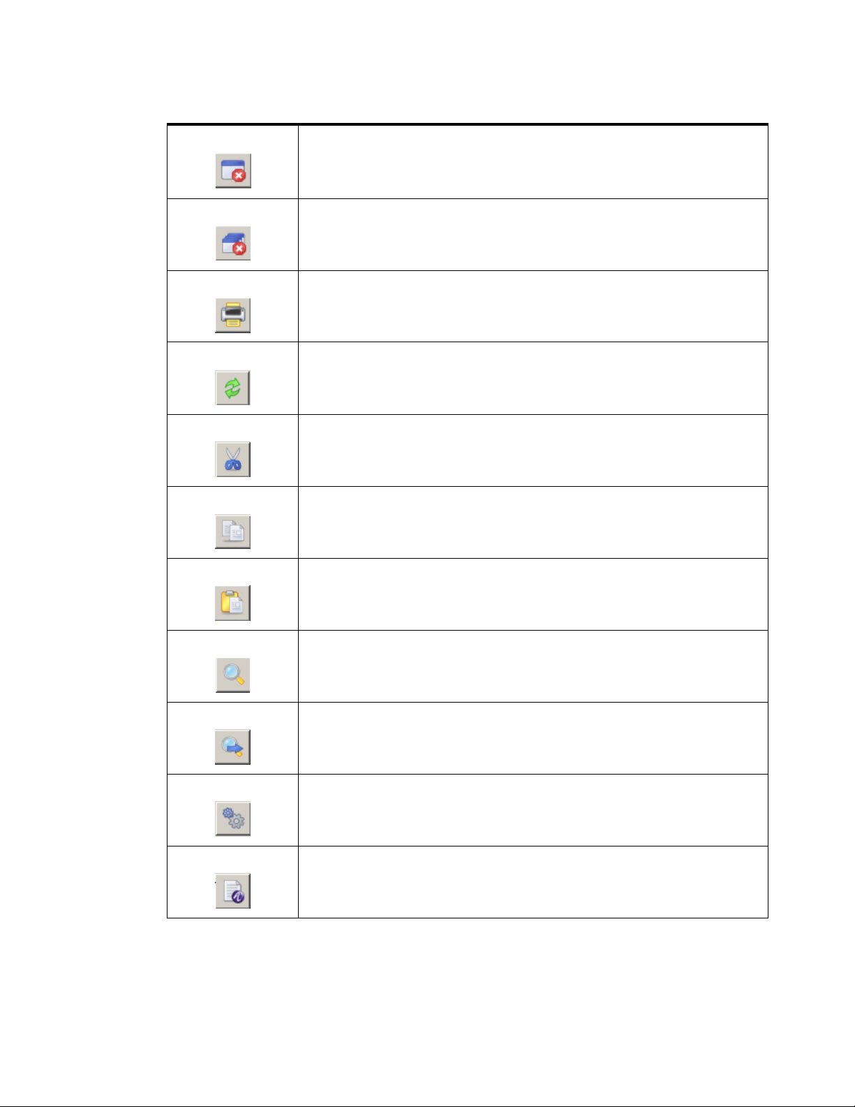
Table 2-2 SMT Tool bar–Buttons
Buttons Description
Log off the currently connected 8950 AAA server. Use the connect menu
option to reconnect.
Show the status of the
8950 AAA Policy server running on the host of the
currently connected 8950 AAA server. When the server is running, the
button is green and if it is not running, the button is red. You can force a
check by clicking the button.
Provides Policy server management and allows control to the 8950 AAA
Policy server. To manage the Policy Server, the following options are
available: the name of the Policy Server, Start Server, Shutdown Server,
Restart Server, Pause Server, and Resume Server.
Show the status of the
8950 AAA Configuration server . When the serv er is
running, the button is green and if it is not running, the button is red. You
can force a check by clicking the button.
Provides configuration server management and allows control to the 8950
AAA Configuration server. To manage the configuration Server, the
following options are available: the name of the Configuration server,
Start Server, Shutdown Server, and Restart Server.
Save changes within the active panel. If no panel is displayed then this
option is not available.
Save changes in all displayed panels. If no panel is displayed then this
option is not available.
Revert to the last saved panel by abandoning changes to the active panel.
The last saved panel is reloaded. If no panel is displayed then this option
is not available. If no panel is displayed then this option is not available.
............................................................................................................................................................................................................................................................
365-360-001 R6.0
Issue 1, December 2008
2-9
Page 34
The Server Management Tool User Interface8950 AAA Server Management Tool Overview
............................................................................................................................................................................................................................................................
Table 2-2 SMT Tool bar–Buttons
Close the active panel. If any changes have been made to that panel, a
panel box appears asking if the changes should be saved. If no panel is
displayed then this option is not available.
Close all displayed panels. If changes have been made to any panel, a
panel box appears asking if the changes should be saved. If no panel is
displayed then this option is not available.
Display a print panel box that provides print options for the user.
Reload the files in the current panel for the
8950 AAA Servers.
Copy selected information to the clipboard and delete the information.
Copy selected information to the clipboard.
Copy information from the clipboard to the selected location.
Search for a text string that is specified within a panel box.
Repeats the last search operation.
Displays Configuration preferences.
Displays License Information.
............................................................................................................................................................................................................................................................
2-10
365-360-001 R6.0
Issue 1, December 2008
Page 35

The Server Management Tool User Interface8950 AAA Server Management Tool Overview
............................................................................................................................................................................................................................................................
Table 2-2 SMT Tool bar–Buttons
Displays System Information.
Displays SMT help.
Displays Technical Support File Packager window for gathering files and
send to technical support.
Allows you to launch test tools in another process.
Allows you to launch database tools in another process.
SMT Navigation Pane
The Navigation pane is a list of panel names categorized according to the functionality, as
shown in Figure 2-8.
............................................................................................................................................................................................................................................................
365-360-001 R6.0
Issue 1, December 2008
2-11
Page 36

The Server Management Tool User Interface8950 AAA Server Management Tool Overview
............................................................................................................................................................................................................................................................
Figure 2-8 SMT–Navigation Pane
SMT Data Pane
There are 5 categories of panels or tools. The navigation pane can be linked to a toolbox
because each panel provides a different tool and each tool can be accessed b y selecting the
panel name. The Navigation pane provides ease-of-use for the SMT user because it allo ws
quick access to any of the listed panels.
Important! Your navigation pane may look slightly different depending upon the
options you have installed and settings in your SMT preferences.
The Data pane is the main area of the SMT window where panels are displayed. It is the
gray area shown in Figure 2-9. Figure 2-10 shows the Data pane with a panel.
............................................................................................................................................................................................................................................................
2-12
365-360-001 R6.0
Issue 1, December 2008
Page 37

The Server Management Tool User Interface8950 AAA Server Management Tool Overview
............................................................................................................................................................................................................................................................
Figure 2-9 SMT–Data Pane without panels
SMT Data pane without Panel
Figure 2-10 SMT–Data Pane with panel
SMT Data pane with Panel
SMT Log Pane
............................................................................................................................................................................................................................................................
365-360-001 R6.0
Issue 1, December 2008
2-13
Page 38

The Server Management Tool User Interface8950 AAA Server Management Tool Overview
............................................................................................................................................................................................................................................................
The Log pane appears at the bottom of the SMT user interface when you click on the SMT
Log tab in the screen. The SMT Log pane is used for displaying log messages of the SMT ,
as shown in Figure 2-11.
Figure 2-11 SMT–SMT Log pane
SMT Log Pane
The SMT Log pane contains buttons that are used for executing commands within the
application. The commands are described in Table 2-3.
Table 2-3 SMT Log Pane–Buttons
Buttons Description
Copies the log information/message to clipboard.
Clears the SMT Log pane.
Prints the SMT Log pane information/message.
Toggles the font in the SMT Log pane message table, from
monspaced font to default font.
Sets the log window to auto scroll. Displays the latest log
message and scrolls the list of log messages as new
messages are added.
SMT Server Log Pane
The Server log pane appears at the bottom of the SMT user interface when you click on
the Server Log tab in the screen. The Server Log pane is used for displaying log messages
from the server, as shown in Figure 2-12.
............................................................................................................................................................................................................................................................
2-14
365-360-001 R6.0
Issue 1, December 2008
Page 39

The Server Management Tool User Interface8950 AAA Server Management Tool Overview
............................................................................................................................................................................................................................................................
Figure 2-12 SMT–Server Log pane
SMT Server Log
The SMT server pane contains buttons that are used for executing commands within the
application. The commands are described in Table 2-4.
Table 2-4 SMT Server Pane–Buttons
Buttons Description
Starts monitoring the Log files.
To pause the monitoring process.
Clears the SMT Server log pane.
Opens the log file in a editor window.
Prints the SMT Server pane information/message.
Sets the log to the desired level.
To select the desired log files from the list of log files
displayed. Default is policy.log file.
............................................................................................................................................................................................................................................................
365-360-001 R6.0
Issue 1, December 2008
2-15
Page 40

The Server Management Tool User Interface8950 AAA Server Management Tool Overview
............................................................................................................................................................................................................................................................
E ND OF STEPS
........................................................................................................................................................
............................................................................................................................................................................................................................................................
2-16
365-360-001 R6.0
Issue 1, December 2008
Page 41

3 Server Management Tool
Command Set
Overview
Purpose
This section describes the SMT command set, focusing on commands that are found
within the SMT menus. There is also information about panel commands and table
management. The last section returns to the topic of the PolicyAssistant and lists a
procedure on how to use the commands to install it.
The following topics are included in this chapter:
SMT menus and their commands
Managing Data in SMT Panels
Sizing Table Columns
Installing the PolicyAssistant and the Policy Flow Editor
SMT menus and their commands
SMT Menus
As described in the section“SMT Menu Bar” on 2-6, the 8950 AAA Server Management
Tool contains five command menus, as follows:
• Server
• Panel
• Edit
• Window
3-1
3-11
3-13
3-13
• Help
This section describes the commands in more detail.
............................................................................................................................................................................................................................................................
365-360-001 R6.0
Issue 1, December 2008
3-1
Page 42

SMT menus and their commandsServer Management Tool Command Set
............................................................................................................................................................................................................................................................
Important! As discussed in Chapter 2, some SMT commands can be issued using
the toolbar. Refer to the section“SMT Toolbar” on 2-8.
Server Connection
The Server menu contains commands that manage the connection between the SMT and
the 8950 AAA server. It is found on the SMT menu bar. During the start procedure, either
a local or remote connection to the configuration server is attempted. A local or remote
connection is necessary to display and enable the SMT GUI.
To break the connection to the 8950 AAA server, select Server on the menu bar and then
click Disconnect from Server. As a result, the GUI disappears from the screen, except for
the title bar and menu bar, and is replaced by the 8950 AAA logo icon.
To connect to a 8950 AAA server, select Server on the menu bar and then click Connect
to Server. As during the start procedure, the Server Management Tool Login popup
window appears so that the user can enter a username, password, and a mode of
connection. After clicking Connect, the GUI appears again.
Managing Panels
The Server Management Tool uses panels to request or display information. Panels
contain one or more tabs that have a variety of fields including text boxes, checkboxes,
and drop-down lists. Some panels contain tables and graphs. Figure 3-1 shows an example
of the SMT interface with a panel displayed.
............................................................................................................................................................................................................................................................
3-2
365-360-001 R6.0
Issue 1, December 2008
Page 43

SMT menus and their commandsServer Management Tool Command Set
............................................................................................................................................................................................................................................................
Figure 3-1 SMT–Data pane with example panel
The Panel menu contains f i ve commands that pro vide user control of the active panel. The
active panel is the most re cently dis p laye d or selected panel within the SMT data pane. In
most cases, the commands available on the Panel menu are also available as buttons on the
panel itself and on the toolbar.
To display the Panel menu, select Panel on the menu bar. The following commands are
available:
• The Save Changes command saves the most recent panel modifications.
• The Revert to Last Saved command restores active panel fields to values that were
saved before any modifications were entered. If the modifications have been saved
then this command will not restore the fields to any previous values.
• The Reload Files command provides the ability to reload modified versions of
configuration files into the running 8950 AAA server.
• The 8950 AAA server loads certain files into memory when it is started, for example,
the list of RADIUS clients. These files can also be reloaded while the server is
running. If memory resident files are modified then they must be reloaded before the
changes will take affect. The files must have been loaded at least once in order to use
this command.
• The Close command closes the panel, removing it from the data pane.
• The Print command prints the contents of the activ e panel. If this command is selected
then the Configuration Print Options panel is displayed, as shown in Figure 3-2.
............................................................................................................................................................................................................................................................
365-360-001 R6.0
Issue 1, December 2008
3-3
Page 44

SMT menus and their commandsServer Management Tool Command Set
............................................................................................................................................................................................................................................................
Figure 3-2 Configuration Print options panel
Select one of the available print options as described below:
• The Print to System Printer option sends the output to the default system printer.
• The Save to Adobe PDF File option saves the output to a PDF file created in the
8950 AAA run subdirectory.
• The Save to Web Page (HTML) option saves the output to an HTML file created in
the 8950 AAA run subdirectory.
• The Print Pre view option displays the output on the screen and provides an option
to print it.
• The Print Configuration command option from the P anel menu displays a list of print
configurations and helps to select the items that you want to print. If this command is
selected then the Configuration Print Options dialog is displayed, as shown in
Figure 3-3.
............................................................................................................................................................................................................................................................
3-4
365-360-001 R6.0
Issue 1, December 2008
Page 45
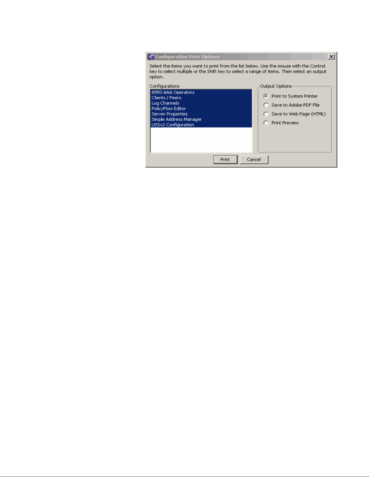
SMT menus and their commandsServer Management Tool Command Set
............................................................................................................................................................................................................................................................
Figure 3-3 Configuration Print options dialog–Print Configuration option
Edit Commands
The Edit menu displays commonly used text editing commands as well as server
preferences and data pane management options. To display the Edit menu, select Edit on
the menu bar. Most of the commands on the Edit menu perform operations that are the
same as with any GUI based application. The SMT Edit menu allows you to perform the
Cut, Copy, Paste, Select All, Find, Find Again, Preferences, Expand all, and Collapse all
commands.
Select Preferences to display the SMT Preferences panel, as shown in Figure 3-4.
............................................................................................................................................................................................................................................................
365-360-001 R6.0
Issue 1, December 2008
3-5
Page 46
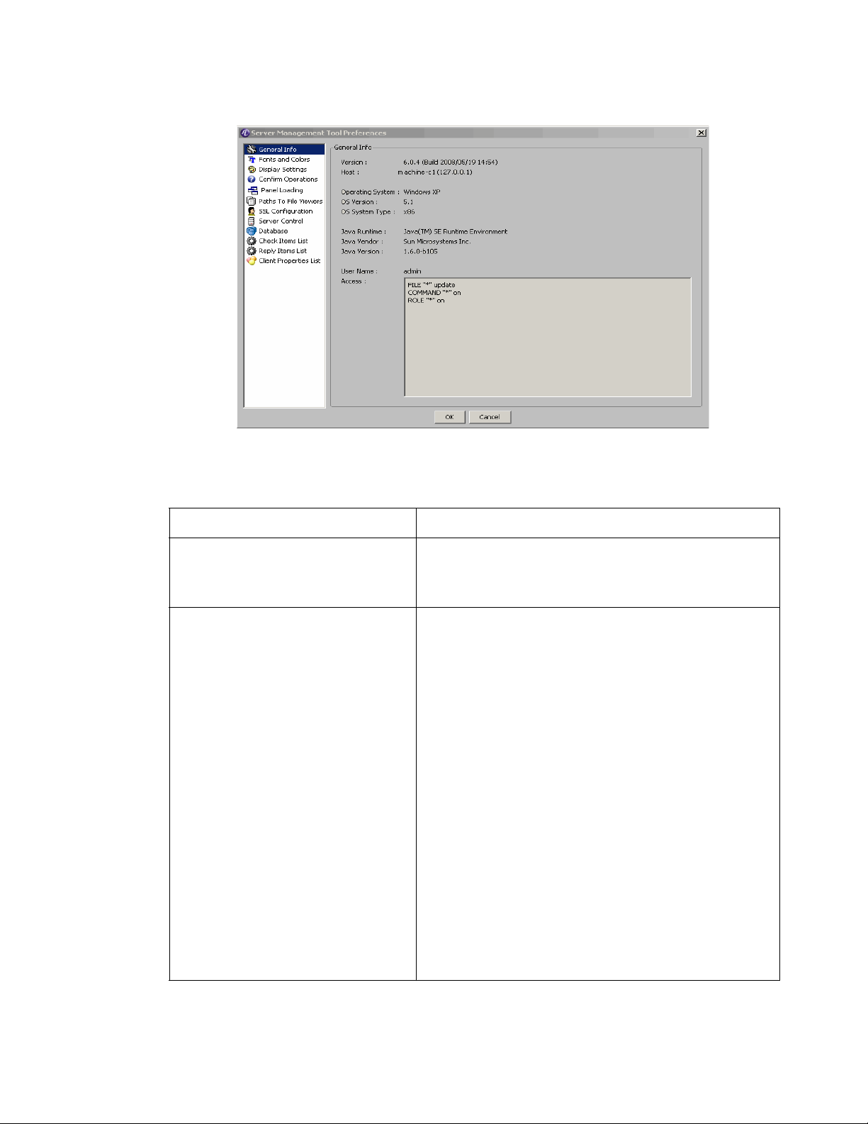
SMT menus and their commandsServer Management Tool Command Set
............................................................................................................................................................................................................................................................
Figure 3-4 SMT–Preferences Panel
Table 3-1 describes the fields of the SMT Preferences Panel.
Table 3-1 SMT Preferences Panel–Properties
Configured Items Description
General Info Displays the general information such as Version
details, Host Information, Operating System
information, Java information, and so on.
Fonts and Colors Controls display fonts, font size, and color schemes.
UI Theme: Choice of color scheme used for SMT user
interface appearance.
Use System Fonts: Choose Yes to keep the default
options. Choose No to edit the required options.
Display Font: Choice of font used for SMT te xt display.
Monospaced Font: Choice of font used for SMT
logging and editing file input.
Font Size: Choice of font size used for SMT text
display.
Use Antialised Font: Choose Yes to use the antialiased
font and choose No to not choose this.
Display Font Preview: Shows an example of selected
display font and size.
Monospaced Font Preview: Shows an example of
selected monospaced font and size.
............................................................................................................................................................................................................................................................
3-6
365-360-001 R6.0
Issue 1, December 2008
Page 47

SMT menus and their commandsServer Management Tool Command Set
............................................................................................................................................................................................................................................................
Table 3-1 SMT Preferences Panel–Properties
Configured Items Description
Display Settings Sets and display desktop components, icons, and
windows sizes and locations. All the settings are Yes or
No buttons. Choose appropriate buttons as per the
requirement(s).
Icons
Show Icons in Resource Outline.
Show Icons on Table Buttons.
Shows Icons on Tabbed Panels.
Windows
Save Window Sizes and Location on Exit.
Use Saved Window Sizes and Locations.
Use Outline Dragging when Moving and Resizing
Panels.
Desktop
Show Status Bar: Display the SMT status bar at the
bottom of the main window. Used for displaying
messages and errors.
Show Tool Bar.
Show Pop-up Tips.
Confirm Operations Specifies the questions that are asked throughout the
SMT.
Confirm Server shutdown for the policy or
configuration servers.
All the settings are Yes or No buttons. Choose
appropriate buttons as per the requirement(s).
Panel Loading Specifies the panels to load in the Server Management
Tool. Any changes to these properties will take effect
next time you run the SMT. You can choose to load or
not load all the available panels b y selecting the Yes/No
buttons that are provided next to each of the available
panel names.
All the settings are Yes or No buttons. Choose
appropriate buttons as per the requirement(s).
............................................................................................................................................................................................................................................................
365-360-001 R6.0
Issue 1, December 2008
3-7
Page 48

SMT menus and their commandsServer Management Tool Command Set
............................................................................................................................................................................................................................................................
Table 3-1 SMT Preferences Panel–Properties
Configured Items Description
Paths to File Viewers Sets directory paths to Web browser, PDF viewer, and
text file viewer.
Web Browser Path: Indicates the location of the
browser.
PDF Viewer Path: Indicates the location of the
application to view PDFs.
Text File Viewer Path: Indicates the location of the
application to view text files.
SSL Configuration The SMT connects to the Configuration Server via
RMI. Use the following to control whether the
connections are secure (SSL). If you change this option,
you must restart the SMT in order for it to take effect.
Use secure remote connections when SMT in Local
Mode: Choose Yes to use the secure remote
connections when the SMT is in Local Mode. Choose
No to not use the secure remote connections when SMT
is in Local Mode.
File for Trusted Certificates: Enter the filename that
needs to be used for this.
Server Control Sets how often the SMT checks the status of the
AAA
and configuration servers.
8950
On Windows platforms, controls 8950 AAA operation
as a Windows service.
Database Enables display of database panels and sets database
connection options.
Java JDBC Class: Specifi es the Ja v a JDBC Class file to
use when connecting and for managing user records in
your database. A database and a JDBC driver are
included with your 8950 AAA server.
JDBC Connection URL: Specifies JDBC connection
URL. If you are connected to a database that is remote,
replace localhost with the host name or IP address of
the remote server.
............................................................................................................................................................................................................................................................
3-8
365-360-001 R6.0
Issue 1, December 2008
Page 49

SMT menus and their commandsServer Management Tool Command Set
............................................................................................................................................................................................................................................................
Table 3-1 SMT Preferences Panel–Properties
Configured Items Description
Check-items List Sets the attributes displayed in the default Check-items
list that is available in various SMT panels. You may
select an attribute from the full dictionary attribute list,
labeled Attributes, on the left side of the pane or enter
your own attribute name in the custom attribute text
box. Click the right arrow to add the attribute to the
default list which appears in the window labeled
Defined Properties.
Reply-items List Sets the attributes displayed in the default Reply-items
list that is available in various SMT panels. You may
select an attribute from the full dictionary attribute list,
labeled Attributes, on the left side of the pane or enter
your own attribute name in the custom attribute text
box. Click the right arrow to add the attribute to the
default list which appears in the window labeled
Defined Properties.
Client Properties List Sets the properties displayed in the default Client
Properties list that is available in various SMT Client
settings panels. You may select an property from the
full property list, labeled Attributes, on the left side of
the pane or enter your own property name in the custom
attribute text box. Click the right arrow to add the
attribute to the default list which appears in the window
labeled Defined Properties.
............................................................................................................................................................................................................................................................
365-360-001 R6.0
Issue 1, December 2008
3-9
Page 50

SMT menus and their commandsServer Management Tool Command Set
............................................................................................................................................................................................................................................................
Figure 3-5 SMT Preferences Panel–Check-Items List
Search/Find
The Find Menu section has two options that helps to find or f ind once again the w ord/item
you want to search.
• Find
• The find message screen is shown in Figure 3-6.
• Find again
Figure 3-6 Find Menu options
Other Edit Menu Commands
Under the Edit menu on the menu bar, the Expand All and Collapse All commands control
the menus within the Navigation pane. By default, all menus are expanded in order to
display all the panel names. To hide the panel names, select Collapse All.
............................................................................................................................................................................................................................................................
3-10
365-360-001 R6.0
Issue 1, December 2008
Page 51

Managing Data in SMT PanelsServer Management Tool Command Set
............................................................................................................................................................................................................................................................
Using the Window Menu to Manage Panels
This menu contains commands that allow the user to manage the panels that are open
within the data pane. Cascade, Maximize, Tile Horizontal, Tile Vertical, and Arrange Icons
display the panels as in other graphical user interfaces.
The Maximize command displays a full view of the active panel. Use the Next Window
command to activate and display the next open panel. The Next Window command can
also be used for cascaded panels. Alternativel y, clicking the title bar of an open panel will
activate it.
Each panel contains three window controls in the top right-hand corner of the panel, as
shown in Figure 3-7.
Figure 3-7 Panel Control Buttons
They allow the user to minimize, maximize, and close the panel. A maximized panel will
contain the Restore Windows control, as shown in Figure 3-8.
Figure 3-8 Panel Restore Button
Clicking this control resizes the panel to its previous form.
Minimizing a panel conver ts it to an icon. The Arr ang e Icons command allows the user to
move all panel icons to the bottom of the data pane. Double-click a minimized icon to
restore it to its previous size.
The Save All command saves the contents of all open panels to the database. The Close All
command removes all panels from the data pane.
The Window menu contains a numbered list of all open panels in order of precedence.
The active panel is always first in the list. Click the name of an open panel in the list to
activate it and make it first in the list.
Managing Data in SMT Panels
About managing data in SMT panel
The SMT uses graphical panels to allow you to easily view, add, change, edit and remove
configuration items. While each of these panels is designed to manage specific data types
(Clients, Attributes, Realms, Users, etc.) they share many common control functions.
Table 3-2 describes six of the most common panel control functions.
............................................................................................................................................................................................................................................................
365-360-001 R6.0
Issue 1, December 2008
3-11
Page 52

Managing Data in SMT PanelsServer Management Tool Command Set
............................................................................................................................................................................................................................................................
Important! In some cases more than one icon may be used for a given function. This
is due to space limitations on some of the panels.
Table 3-2 Panel Control Functions
Action Description Button Icon
Insert Add a record in the current panel after the
selected row. If no row is selected, the
record is inserted at the end of the table or
list. Clicking this button typically displays
a panel to enter information.
Edit Edit data for an existing record. Clicking
this button typically displays a panel to
enter information.
Delete Remove the selected row from the current
panel's table.
Delete All Remove all records from the current
panel.
Make a Copy of
selected record
Duplicate the selected record. The
duplicate record is inserted after the
selected record.
Row Order Some panels contain order sensitive data.
When using these panels, you may change
the order of records by selecting a record
and then using the Up-Down buttons as
appropriate.
............................................................................................................................................................................................................................................................
3-12
365-360-001 R6.0
Issue 1, December 2008
Page 53

Sizing Table ColumnsServer Management Tool Command Set
............................................................................................................................................................................................................................................................
Sizing Table Columns
Resizing the table columns
You can resize columns in a table. To resize a column, pass the mouse over the line
dividing the table columns in the title row, that is, the top row of the table where the
column names appear. The mouse changes to a resize pointer. Click and drag in either
direction. If a column is too narrow to display a table entry, a small arrowhead appears to
indicate that data has been truncated.
Installing the PolicyAssistant and the Policy Flow Editor
Installing PolicyAssistant
You can choose to install and work on either the Policy Flow Editor or the Policy Assistant
at a time. By default, the Policy Flow Editor is enabled when you install the 8950 AAA
GUI. To enable the Policy Assistant, perform the following steps.
1. Select Policy Flow Editor from the Navigation pane under the Configuration Tools
section. The Policy Flow Editor panel is displayed as shown in Figure 3-9.
Figure 3-9 SMT–Policy Flow Editor Panel
2. Click the Install PolicyFlow... to open the PolicyFlow Installation page. The
PolicyFlow Installation page is displayed as shown in Figure 3-10.
............................................................................................................................................................................................................................................................
365-360-001 R6.0
Issue 1, December 2008
3-13
Page 54

Installing the PolicyAssistant and the Policy Flow EditorServer Management Tool Command Set
............................................................................................................................................................................................................................................................
Figure 3-10 SMT–Policy Flow Installation page
3. Select Install Policy Assistant and click the Install Policy Flow button. The
following message appears.
Figure 3-11 SMT–Policy Flow Installation warning message
4. Click Yes to continue.
Important! If the Policy Flow Assistant is already installed, the following message
appears.
Figure 3-12 SMT–Policy Flow warning message
5. Click Yes to continue. It will take a few seconds and when the installation is complete,
the following message appears.
............................................................................................................................................................................................................................................................
3-14
365-360-001 R6.0
Issue 1, December 2008
Page 55

Installing the PolicyAssistant and the Policy Flow EditorServer Management Tool Command Set
............................................................................................................................................................................................................................................................
Figure 3-13 SMT–Policy Flow Installation success message
6. Click OK and close the SMT GUI and restart the application.
7. After you restart, instead of the PolicyFlow Editor, you will see the entry Policy
Assistant in the Navigation pane under the Configuration Tools section.
Read through Chapter 9, “Using the 8950 AAA Policy Assistant in Server Management
Tool” for more information on the PolicyAssistant. While the PolicyAssistant is very easy
to use, there are some decisions you must make to successfully set up 8950 AAA.
Installing PolicyFlow Editor
1. To enable the PolicyFlow Editor, perform the following steps:
2. In the PolicyAssistant panel, click Install PolicyFlow.. to open the PolicyFlow
Installation page. The PolicyFlow Installation page is displayed as shown in
Figure 3-10.
3. Select Build Your Own PolicyFlow and click the Install Policy Flow button. A
warning message, as shown Figure 3-11 appears.
4. Click Yes to continue.
5. If the Policy Flow Editor is already installed, one more warning message as shown
Figure 3-12 appears.
6. Click Yes to continue. It will take a few seconds and when the installation is complete,
the following message appears.
Figure 3-14 SMT-Policy Flow Installation success message
7. Click OK and close the SMT GUI and restart the application.
8. Once you restart, you will see that instead of the Policy Assistant, you will see the
entry Policy Flow Editor in the Navigation pane under the Configuration Tools
section.
Read through Chapter 8, “Using the 8950 AAA Policy Flow Editor” for more information
on the PolicyFlow Editor.
............................................................................................................................................................................................................................................................
365-360-001 R6.0
Issue 1, December 2008
3-15
Page 56

Installing the PolicyAssistant and the Policy Flow EditorServer Management Tool Command Set
............................................................................................................................................................................................................................................................
Installing PolicyFlow Editor for a configuration set
To enable the PolicyFlow Editor for a configuration set, perform the following steps:
1. In the PolicyFlow Installation page, as shown in Figure 3-10, select Install a
Configuration Set.
2. The drop-down list box is activated and this shows a list of
pre-configured configuration sets.
3. Select one of the configuration set from the list and click the Install Policy Flow
button. A warning message, as shown Figure 3-15 appears.
Figure 3-15 SMT–Policy Flow–already existing warning message
4. Click Yes to continue. It will take a few seconds and when the installation is complete,
the following message appears.
Figure 3-16 SMT-Policy Flow Installation success message
5. Click OK and close the SMT GUI and restart the application.
6. Once you restart, you will see that instead of the Policy Assistant, you will see the
entry Policy Flow Editor in the Navigation pane under the Configuration Tools
section.
Important! If you click on the Policy Flow Editor in the Navigation pane, the SMT
will display the configuration set that was selected in step 2.
E ND OF STEPS
........................................................................................................................................................
............................................................................................................................................................................................................................................................
3-16
365-360-001 R6.0
Issue 1, December 2008
Page 57

4 Managing 8950 AAA
Servers
Overview
Purpose
This section discusses how the SMT is used to control the behavior of 8950 AAA servers
and to define properties associated with the servers.
The following topics are included in this chapter:
Configuring Server Properties
Policy Server tab
Universal State Server tab
Configuration Server tab
Configuring Server Properties
About Configuring the Server properties
Before 8950 AAA can start processing AAA (“triple-A”) traffic, it must first be
configured for your local environment and specific policy needs. 8950 AAA allows the
user to control the behavior of the 8950 AAA RADIUS server by setting configuration
options. The various configuration options control ho w 8950 AAA servers process packets
and manage data flow.
The configuration options are provided within the Server Properties Panel. To open this
panel, locate Configuration Tools within the SMT Navigation Pane and select Server
Properties. The Server Properties Panel appears as shown in Figure 4-1.
4-1
4-2
4-28
4-38
............................................................................................................................................................................................................................................................
365-360-001R6.0
Issue 1, December 2008
4-1
Page 58

Policy Server tabManaging 8950 AAA Servers
............................................................................................................................................................................................................................................................
Figure 4-1 Server Properties Panel
The Server Properties Panel
Use the Server Properties panel to control the behavior of the 8950 AAA serv ers including
how the 8950 AAA server processes packets and manages data flow between its servers
and clients.
The Server properties panel display 3 tabs as follows:
• Policy Server
• Universal State Server
• Configuration Server
Each of these tabs allow you to configure different types of interface.
Policy Server tab
About the Policy Server tab
The Policy Server tab allows you to configure the entities in the policy server.
By default, when you click on the Server Properties option, the Policy Server tab is
displayed. In the Policy Server tab, by def ault, the Web Interface Configuration panel is
displayed as shown in Figure 4-1.
............................................................................................................................................................................................................................................................
4-2
365-360-001R6.0
Issue 1, December 2008
Page 59

Policy Serve r ta bManaging 8950 AAA Servers
............................................................................................................................................................................................................................................................
Web Interface Configuration Panel
The Web Interface Configuration panel specifies the configuration values for running the
built-in web interface. The web interface allo ws you to query statistical information about
the 8950 AAA servers from a standard web browser . This interf ace is automatically started
when you run the 8950 AAA servers.
Important! When assigning a port to the address field, make sure you do not have
any conflicting services using this port.
Table 4-1 lists the configurable entities of this panel.
Table 4-1 Policy Server Tab–Configurable properties
Configurable Properties Description
HTTP Address Sets the address for the HTTP connection to the built-in
web interface. Default is ‘*:9080’.
HTTP Directory Specifies the root directory where the server looks for its
HTML files used by its web server. If a full path is not
included, this filename is relative to the run directory.
Default is ‘..\html\’.
HTTP Secure Address Sets the address for secure (HTTPS) HTTP connection to
Admin Interface Configuration Panel
To go to the Admin Interface Configuration panel, click on the Admin Interface option
from the Policy Server data pane menu options on the left side. The Admin Interface
Configuration panel is displayed as shown in Figure 4-2.
the built-in web interface. Default is ‘*:9443’.
............................................................................................................................................................................................................................................................
365-360-001R6.0
Issue 1, December 2008
4-3
Page 60
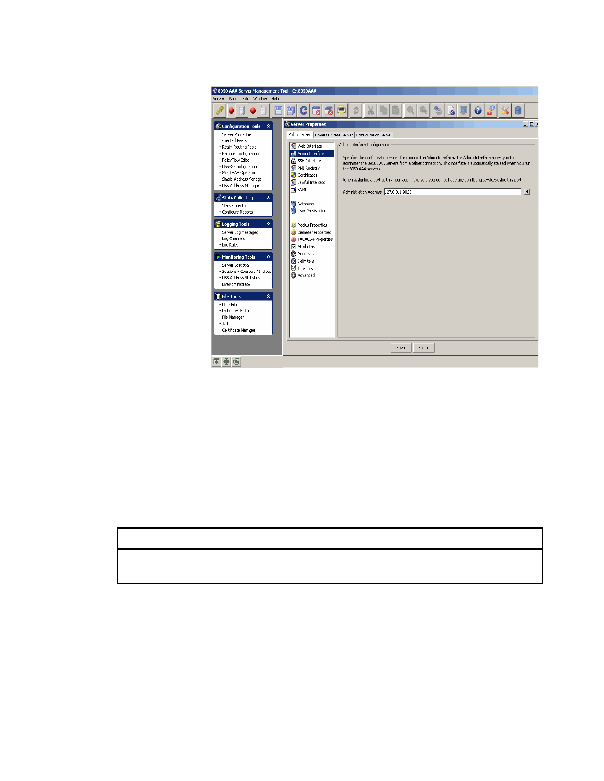
Policy Server tabManaging 8950 AAA Servers
............................................................................................................................................................................................................................................................
Figure 4-2 Policy Server–Admin Interface Configuration Panel
The Admin Interface Configuration panel specifies the configuration values for running
the Admin interface. The Admin interface allows you to administer the 8950 AAA serv ers
from a telnet connection. This interface is automatically started when you run the 8950
AAA servers.
Important! When assigning a port to this interface, make sure you do not have any
conflicting services using this port.
Table 4-2 lists the configurable entities of this panel.
Tab l e 4- 2 Ad m i n I n t er f a ce C o nfiguration panel–properties
Configurable Properties Description
Administration Address Sets the address for telnet connections to the built-in
SSH Interface Configuration Panel
To go to the SSH Interface Configuration panel, click on the SSH Interface option from
the Policy Server data pane menu options on the left side. The SSH Interface
Configuration panel is displayed as shown in Figure 4-3.
admin interface. Default is ‘127.0.0.1:9023’.
............................................................................................................................................................................................................................................................
4-4
365-360-001R6.0
Issue 1, December 2008
Page 61
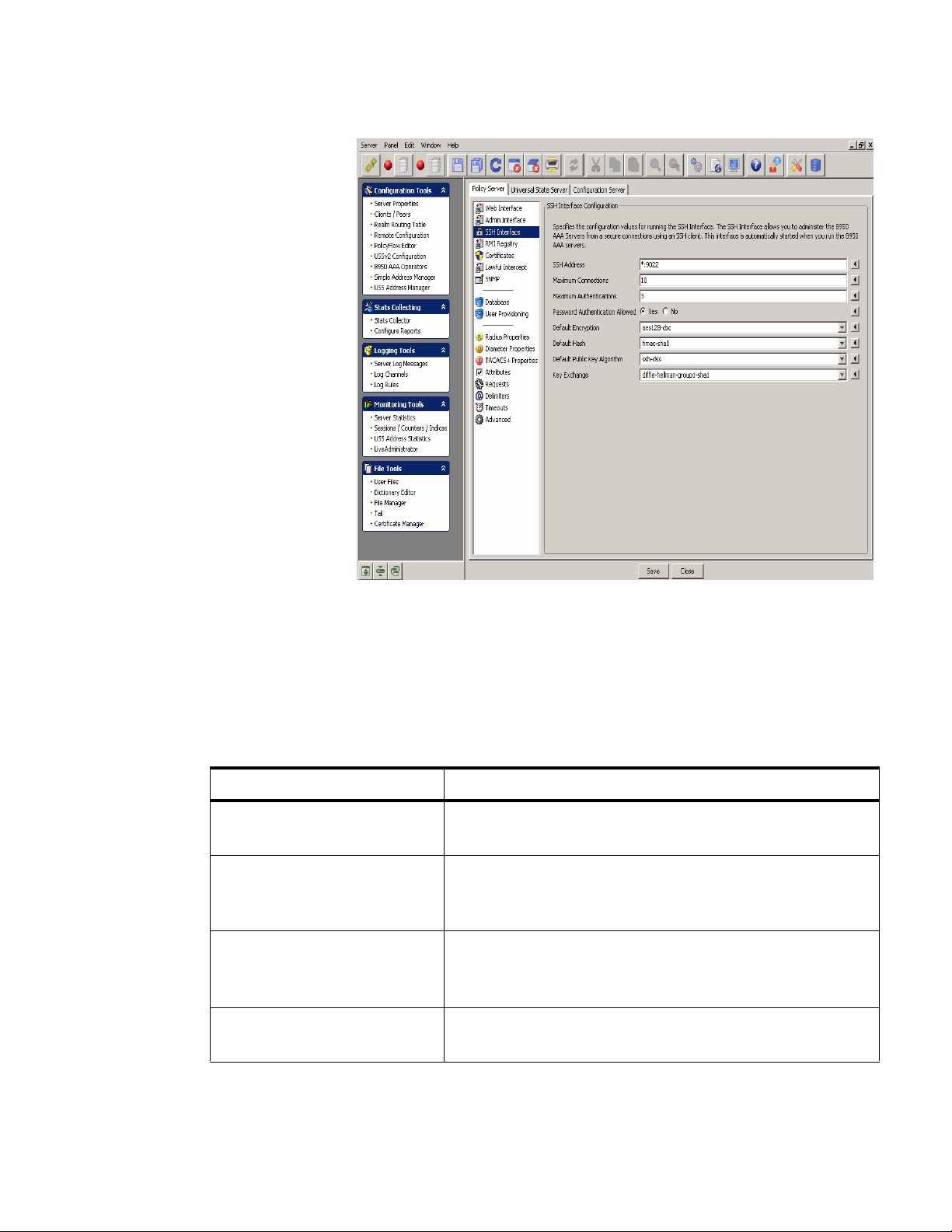
Policy Serve r ta bManaging 8950 AAA Servers
............................................................................................................................................................................................................................................................
Figure 4-3 Policy Server–SSH Interface Configuration Panel
The SSH Interface Configuration panel specifies the configuration values for running the
SSH interface. The SSH interface allows you to administer the 8950 AAA servers from
secure connections using an SSH client. This interface is automatically started when you
run the 8950 AAA servers.
Table 4-3 lists the configurable entities of this panel.
Table 4-3 SSH Interface–Properties
Configurable Properties Description
SSH Address Specifies the address and port the server listens to, default is
‘*:9022’ and port number 0 means do not start the SSH at all.
Maximum Connections Specifies the maximum number of simultaneous connections
against the SSH server at any given time. Entering a value of
0 disables the SSH Service.
Maximum Authentications Specifies the maximum number of unsuccessful
authentication attempts in a row that a user is permitted
before being kicked off.
Password Authentication
Allowed
Specifies that the password authentication is allowed.
Password forces a standard username and password login.
............................................................................................................................................................................................................................................................
365-360-001R6.0
Issue 1, December 2008
4-5
Page 62

Policy Server tabManaging 8950 AAA Servers
............................................................................................................................................................................................................................................................
Table 4-3 SSH Interface–Properties
Configurable Properties Description
Default Encryption Specifies the default encryption to use for connections if not
specified by the client.
Default Hash Specifies the default hash algorithm to use for connections if
not specified by the client.
Default Public Key Algorithm Specifies the default public key algorithm to use for
connections if not specified by the client.
Key Exchange Specifies the key exchange configuration. Currently only
‘diffie-hellman-group1-sha1’ is supported.
RMI Registry Configuration Panel
The Remote Method Inv ocation (RMI) Registry property is used to set the port for running
the RMI Registry. The panel contains one field that contains the Registry Port that the
server uses for accepting connections from the SMT for retrieving statistical information
about statistics, counters, indices, and port status. This port is used to replicate data
between the primary and secondary state servers.
To go to the RMI Registry Configuration panel, click on the RMI Registry option from
the Policy Server data pane menu options on the left side. The RMI Registry
Configuration panel is displayed as shown in Figure 4-4.
............................................................................................................................................................................................................................................................
4-6
365-360-001R6.0
Issue 1, December 2008
Page 63

Policy Serve r ta bManaging 8950 AAA Servers
............................................................................................................................................................................................................................................................
Figure 4-4 Policy Server–RMI Registry Configuration Panel
The RMI Registry Configuration panel specifi es the port for running the RMI Re gistry for
both secured and non secured. The RMI Registry is used to get statistical information from
the RADIUS Server and the StateServer from the SMT. It is also used in StateServer
replication to synchronize the active sessions.
Table 4-4 lists the configurable entities of this panel.
Table 4-4 RMI Registry–Properties
Configurable Properties Description
Registry Port Specifies the Registry Port the server uses for
Secure Registry Port Same as Registry Port. Default value is ‘9100’.
SMT and Server Certificates Panel
To go to the SMT and Server Certificates panel, click on the Certificates option from the
Policy Server data pane menu options on the left side. The SMT and Server Certificates
Configuration panel is displayed as shown in Figure 4-5.
accepting connections from the SMT to retrieve
statistical information about statistics, counters,
indexes, and port status. This port is used to replicate
data between the primary and secondary state servers.
Default value is ‘9099’.
............................................................................................................................................................................................................................................................
365-360-001R6.0
Issue 1, December 2008
4-7
Page 64

Policy Server tabManaging 8950 AAA Servers
............................................................................................................................................................................................................................................................
Figure 4-5 Policy Server–SMT and Server Certificates Panel
The SMT and Server Certificates panel specifies the names of the certificate files to use
for secure connections (SSL) for RMI connections and communications between the
primary and secondary state servers for replication.
Table 4-5 lists the configurable entities of this panel.
Table 4-5 SMT and Server Certificates panel–Properties
Configurable Properties Description
Server Certificate File The server certificate file. Default file is ‘server.pem’.
Trusted Certificates File The trusted certificates file. Default file is
Lawful Intercept Properties Panel
To go to the Lawful Intercept Properties panel, click on the Lawful Interc ept option from
the Policy Server data pane menu options on the left side. The Lawful Intercept Properties
panel is displayed as shown in Figure 4-6.
‘trusted.pem’.
............................................................................................................................................................................................................................................................
4-8
365-360-001R6.0
Issue 1, December 2008
Page 65

Policy Serve r ta bManaging 8950 AAA Servers
............................................................................................................................................................................................................................................................
Figure 4-6 Policy Server–Lawful Intercept Properties Panel
SNMP Panel
The Lawful Intercept Properties panel specifies the configuration values for the policy
server lawful intercept service.
The Lawful Intercept service allows the interception of telecommunications by law
enforcement authorities (LEA’s) and intelligence services, in accordance with local law
and after following due process and receiving proper authorization from competent
authorities. Various countries have different rules with regards to lawful interception. In
the United states the law is known as CALEA, in CIS countries as SORM.
Table 4-6 lists the configurable entities of this panel.
Table 4-6 Lawful Intercept Properties Panel–Properties
Configurable Properties Description
Lawful Intercept Address Specifies the address for lawful intercept target
administrative messages. The value of zero (0)
disables the address.
The SNMP properties can configure the SNMP agent built into the 8950 AAA server.
8950 AAA acts as an SNMP agent counting events that it receives.
............................................................................................................................................................................................................................................................
365-360-001R6.0
Issue 1, December 2008
4-9
Page 66

Policy Server tabManaging 8950 AAA Servers
............................................................................................................................................................................................................................................................
T o go to the Simple Netw ork Management Protocol (SNMP) Properties panel, click on the
SNMP option from the Policy Server data pane menu options on the left side. The SNMP
properties panel is displayed as shown in Figure 4-7.
Figure 4-7 Policy Server–SNMP Properties Panel
The SNMP properties panel specifies the configuration v alues for the Polic y server SNMP
agent. The SNMP agent allows the SNMP clients to retrieve statistical information about
request processing from the policy server through a Radius MIB.
If the SNMP address is set to a valid non-zero address:port combination, the policy server
starts a SNMP agent listener on that address.
Table 4-7 lists the configurable entities of this panel.
Table 4-7 SNMP properties panel–Properties
Configurable Properties Description
SNMP Address Specifies the port to listen to the SNMP requests on.
Entering a value of ‘0’ disables the listener. The SNMP
address defaults to zero (0).
Read Community Specifies the read co mmunity v alue that controls access
to read variables. The read community value defaults to
‘public’.
............................................................................................................................................................................................................................................................
4-10
365-360-001R6.0
Issue 1, December 2008
Page 67

Policy Serve r ta bManaging 8950 AAA Servers
............................................................................................................................................................................................................................................................
Table 4-7 SNMP properties panel–Properties
Configurable Properties Description
Write Community Specifies the write community value that controls
access to write variables. The write community ha s no
default values.
System Contact Specifies the contact name of the SNMP agent.
System Name Specifies the name of the SNMP agent.
System Location Specifies the location of the SNMP agent.
Allow SNMP Version 1 If enabled, the policy server SNMP agent accepts
version 1.
Allow SNMP Version 2 C If enabled, the policy server SNMP agent accepts
version 2 C.
Allow SNMP Version 3 If enabled, the policy server SNMP agent accepts
version 3.
SNMP Version 3 Engine ID This value must be globally unique and is calculated by
Database Configuration Panel
To go to the Database Configuration panel, click on the Database option from the Policy
Server data pane menu options on the left side. The Database Configuration panel is
displayed as shown in Figure 4-8.
the policy server upon start up using the proposed
algorithm in RFC-3411 as follows: The first four octets
of the engineID are set to the 8950 AAA enterprise
number ‘831’ with the very first bit set to 1 (8000033f),
octet number 5 is set to 01 to indicate an IPv4 address
and finally octets 6 through 9 are set the servers IP
address. This address is either the value of the server
property SNMP address, or if that address is wildcard
(*), the first non-loopback IPv4 address of the system.
Setting the SNMP V3 engine ID value explicitly will
disable the above algorithm and it is not recommended
unless absolutely necessary.
............................................................................................................................................................................................................................................................
365-360-001R6.0
Issue 1, December 2008
4-11
Page 68

Policy Server tabManaging 8950 AAA Servers
............................................................................................................................................................................................................................................................
Figure 4-8 Policy Server–Database Configuration Panel
The Database Configuration panel specifies the conf iguration v alues for the built-in Derb y
database. If the port is a non-zero, the database is automatically started when you run the
policy server.
Important! When assigning ports to the database, make sure you do not have any
conflicting services using this port.
This panel also specifies the configuration values for the built-in Hypersonic database.
The Hypersonic database is no longer enabled by default. It is only a v ailable for backward
compatibility. If the port is a non-zero value, the database is automatically started when
you run the policy server.
Important! When assigning ports to the database, make sure you do not have any
conflicting services using the port.
Table 4-8 lists the configurable entities of this panel.
Table 4-8 Database Configuration Panel–Properties
Configurable Properties Description
Derby Address Sets the listen addresses for Apache Derb y database server .
............................................................................................................................................................................................................................................................
4-12
365-360-001R6.0
Issue 1, December 2008
Page 69

Policy Serve r ta bManaging 8950 AAA Servers
............................................................................................................................................................................................................................................................
Table 4-8 Database Configuration Panel–Properties
Configurable Properties Description
Derby System Home Sets the location of the derby database files. This is the
name of sub-directory under the 8950 AAA base
installation directory. Sets the derby.system.home Derby
property.
Derby Log level Sets the 8950 AAA log le vel that messages from the Derby
database server will be logged.
Derby Severity Sets the le vel of the De rby messages that Derby will output
to our logging system. These messages are logged at the
Derby log level in the AAA logging system.
Enable Driver Trace If enabled, the Derby driver level messages are logged in
the policy server log.
Hypersonic configuration entity details
Hypersonic Address Sets the listen addresses for the Hypersonic database
server.
Hypersonic Shutdown Sets the shutdown mode for the database. NORMAL:
Log File Size Sets the maximum size (in megabytes) that the database
User Provisioning Panel
To go to the User Provisioning System panel, click on the User Pr o v isio ni ng option from
the Policy Server data pane menu options on the left side. The User Provisioning System
panel is displayed as shown in Figure 4-9.
Checkpoints the database normally. IMMEDIATELY:
Equivalent to a poweroff or crash. COMPACT: Compacts
the tables, closes the log, and checkpoints the database.
log file can reach before an automatic checkpoint occurs.
............................................................................................................................................................................................................................................................
365-360-001R6.0
Issue 1, December 2008
4-13
Page 70
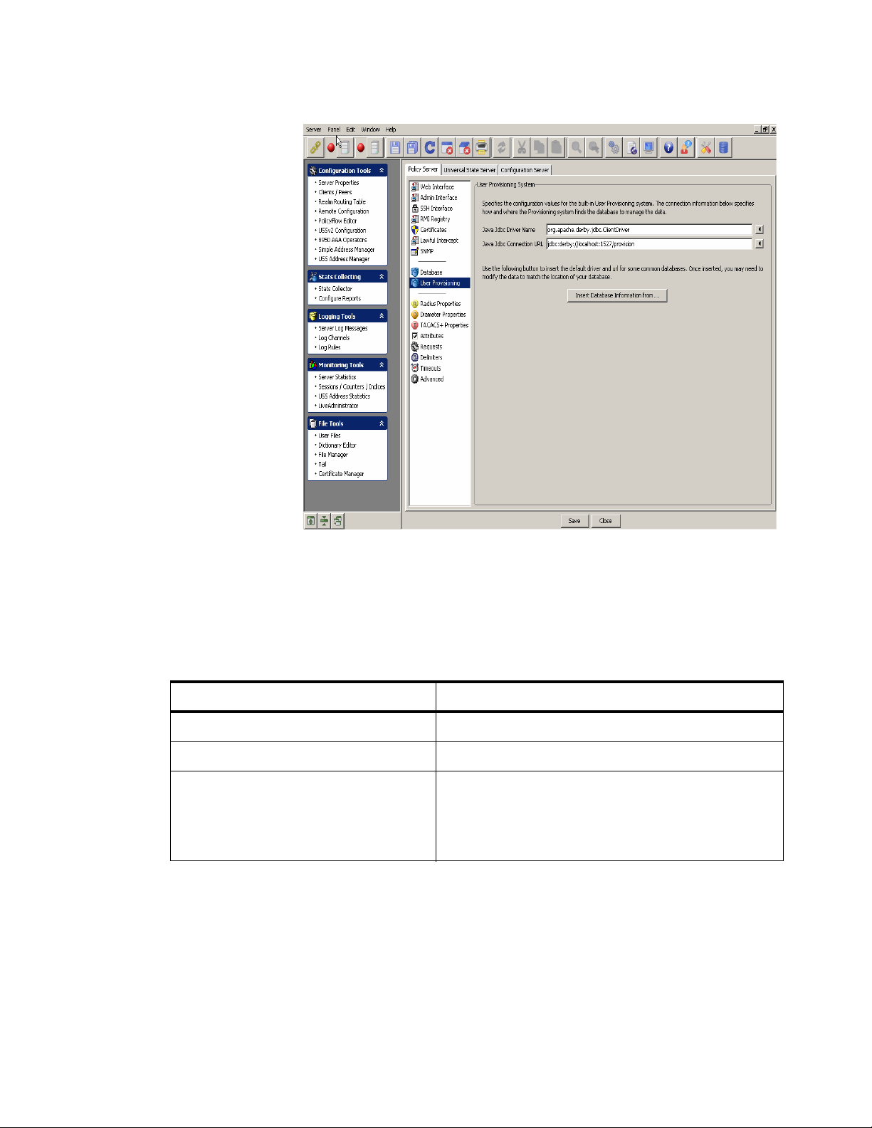
Policy Server tabManaging 8950 AAA Servers
............................................................................................................................................................................................................................................................
Figure 4-9 Policy Server–User Provisioning System Panel
The User Provisioning system specifies the configuration values for the built-in User
Provisioning system. The connection information below specifies how and where the
provisioning system finds the database to manage the data.
Table 4-9 lists the configurable entities of this panel.
Table 4-9 User Provisioning System panel–Properties
Configurable Properties Description
Java JDBC Driver name The Java Jdbc driver name.
Java JDBC Connection URL The Java Jdbc connection URL.
Insert Database Information from.. Click this to get a list of Database names that are
Radius Properties Panel
To go to the RADIUS Properties panel, click on the Radius Properties option from the
Policy Server data pane menu options on the left side. The Radius properties panel is
displayed as shown in Figure 4-10.
available from which you can select any of the
database type to insert the database information
from.
............................................................................................................................................................................................................................................................
4-14
365-360-001R6.0
Issue 1, December 2008
Page 71

Policy Serve r ta bManaging 8950 AAA Servers
............................................................................................................................................................................................................................................................
Figure 4-10 Policy Server–RADIUS Properties Panel
The RADIUS properties panel specifies the configuration values for the Policy server
when processing Radius requests.
Table 4-10 lists the configurable entities of this panel.
Table 4-10 Radius Properties panel–Properties
Configurable Properties Description
Authentication Addresses Sets the listening addresses for authentication requests. This
value is a comma separated l ist of address:port values. If
address is omitted, it is assumed to be *. If the port is omitted, it
defaults to 1812. Default value is *:1645, *:1812. If this
property is not defined or set to zero (0) authentication requests
will not be processed.
Accounting Addresses Sets the listening addresses for accounting requests. This value
is a comma separated list of address:port values. If address is
omitted, it is assumed to be *. If the port is omitted, it defaults
to 1813. Default value is *:1646, *:1813. If this property is not
defined or set to zero (0) authentication requests will not be
processed.
............................................................................................................................................................................................................................................................
365-360-001R6.0
Issue 1, December 2008
4-15
Page 72

Policy Server tabManaging 8950 AAA Servers
............................................................................................................................................................................................................................................................
Table 4-10 Radius Properties panel–Properties
Configurable Properties Description
Dynamic Authentication
Addresses
Sets the listening address for dynamic authentication requests.
This value is a comma separated list of address:port values. If
address is omitted, it is assumed to be *. If the port is omitted, it
defaults to 3799.
Truncate Attributes at First
NUL
If enabled, attributes are truncated at the first NUL found in the
value. If disabled, the attribute values are not truncated. This
enables support for NAS devices that send NUL characters in
their attributes.
Add NUL to string attributes If enabled, a NUL is appended to the end of plain string
attributes in response requests to the NAS. This enables supp ort
for NAS devices that send NUL characters in their attributes.
Check Duplicates If enabled, the server checks to see if the request received is a
duplicate of a previously received request. Duplicates are
detected by a combination of the Source IP, Source Port, and
Packet Authenticator. The default setting is true. This property
can be set on a per-client basis in the Client properties.
Check Authenticators If enabled, the policy server checks the request authenticator
and if not verified, the request is dropped.
Discard request when error If enabled, the policy server discards packets when a method
returns an error. If not enabled, the policy server rejects the
packet.
Max RADIUS packet size Specifies the maximum RADIUS packet size that is allowed.
The default is 4096 bytes.
Receive buffer size for
RADIUS
Send buffer size for
RADIUS
Type of Service (Traffic
Class)
Response Cache Timeout
Enabled
Specifies the size of the system UDP receive buffer assigned to
the local socket.
Specifies the size of the system UDP send buffer assigned to the
local socket.
Specifies the traffic class or type-of-service octet in the
RADIUS IP header.
If enabled, the policy server caches responses for the time
specified in the corresponding timeout property. If not enabled,
responses are not cached.
............................................................................................................................................................................................................................................................
4-16
365-360-001R6.0
Issue 1, December 2008
Page 73

Policy Serve r ta bManaging 8950 AAA Servers
............................................................................................................................................................................................................................................................
Table 4-10 Radius Properties panel–Properties
Configurable Properties Description
Response Cache Timeout When responding to the RADIUS requests, the policy server
can remember (cache) the responses. If the response is sent, but
lost and the NAS resends the same request, the policy server
can respond with the cached response and not have to process
the request again. This property sets how long the policy server
keeps cached entries before discarding them.
Diameter Properties Panel
To go to the Diameter Properties panel, click on the Diameter Properties option from the
Policy Server data pane menu options on the left side. The Diameter properties panel is
displayed as shown in Figure 4-11.
Figure 4-11 Policy Server–Diameter Properties Panel
The Diameter properties panel specifies the configuration values for the Policy server
when processing Diameter requests.
............................................................................................................................................................................................................................................................
365-360-001R6.0
Issue 1, December 2008
4-17
Page 74

Policy Server tabManaging 8950 AAA Servers
............................................................................................................................................................................................................................................................
Table 4-11 lists the configurable entities of this panel.
Table 4-11 Diameter Properties panel–Properties
Configurable Properties Description
Diameter Address Sets the listen addresses for diameter requests. This
value is a comma separated list of address:port values. If
address is omitted, it is assumed to be *. If the port is
omitted, it defaults to 3868. Default value is *:3868. If
this property is not defined or set to zero (0) diameter
requests will not be processed.
Origin Realm Specifies the origin realm.
Origin Host Specifies the origin host. Useful when testing diameter
when no outside network connection is available.
Peer Socket Timeout Specifies the amount of time (in milliseconds) allowed
before generating a peer state machine ‘Timeout’ event
as defined in RFC-3588, paragraph 5.6, during
connection establishment with a remote peer. As an
example, when an initiating peer attempts to connect to
a remote peer in the Closed state, it starts a timer
simultaneously with the connection request being sent.
Then, in ‘W ait-Conn-Ack’, the state that follows Closed,
a Timeout ev ent is generated if no other event intervenes
and the connection state is brought back to Closed while
noting the peer as unavailable.
Peer Idle Timeout Specifies the time in milliseconds the peer is timed out if
idle.
Peer Idle Holdoff Specifies the time in milliseconds before a peer is f ailed
back after being suspended (if it was failed over at the
time of suspension). Peers are getting suspended as a
result of an idle-timeout, either on the local side or by
the remote server requesting a connection shut down.
Without this time-out and no extended requests,
suspended peers would be kept in the failed over state
indefinitely if they were failed over when asked to
suspend.
............................................................................................................................................................................................................................................................
4-18
365-360-001R6.0
Issue 1, December 2008
Page 75

Policy Serve r ta bManaging 8950 AAA Servers
............................................................................................................................................................................................................................................................
Table 4-11 Diameter Properties panel–Properties
Configurable Properties Description
Device Watchdog Rate The AAA Transport Profile document defines a
heartbeat mechanism for maintaining connection state
through the periodic exchange of ‘Device-Watchdog’
messages between two peers in their connected state.
This parameter defines the average time (in
milliseconds) between transmissions of consecutive
‘Device-Watchdog-Request’ message. Note that the
time is an average for the local server as a random skew
is applied to the value for each emitted watchdog
request. The timer is also reset by other inter-peer
traffic.
Outstanding Diameter Request
Lifetime
Specifies how many milliseconds to keep an outbound
request pending without an answer before it is discarded
and a time-out event is sent back to the policy engine.
Minimum Accepted Redirect Cache
Time
Specifies the minimum value accepted as a real value in
a ‘Redirect-Max-Cache-Time’ AVP in a Diameter
answer where result-code is set to DIAMETERREDIRECT-INDICATION. If ‘Redirect-Max-CacheTime’ is less than this value, the redirect indication is
treated the same as a DONT-CACHE Redirect-HostUsage indication.
Default Advertised Redirect Cache
Time
Specifies the default value in seconds inserted into a
locally generated redirect answer’s ‘Redirect-MaxCache-Time’ AVP if an explicit value is not defined by
the policy flow.
Maximum Redirect Traversal Depth The diameter server builds up a graph that models the
received redirect indications as they are received
(example, if the host alpha indicated redirection to beta
and beta indicated redirection to gamma, the graph
would be alpha -> beta -> gamma.) This parameter
defines the maximum allowed depth of the redirection
graph before a message is considered undeliverabl e.
Maximum Route Attempts Specifies the maximum number of unique peers that are
tried for routing of a request before returning an answer
with DIAMETER_UNABLE_TO_DELIVER to the
originator.
Less Specific Route Fallback Setting to true enables fall-back to less specific route
matching in the route table should all destinations in the
current entry fail to accept the request.
............................................................................................................................................................................................................................................................
365-360-001R6.0
Issue 1, December 2008
4-19
Page 76
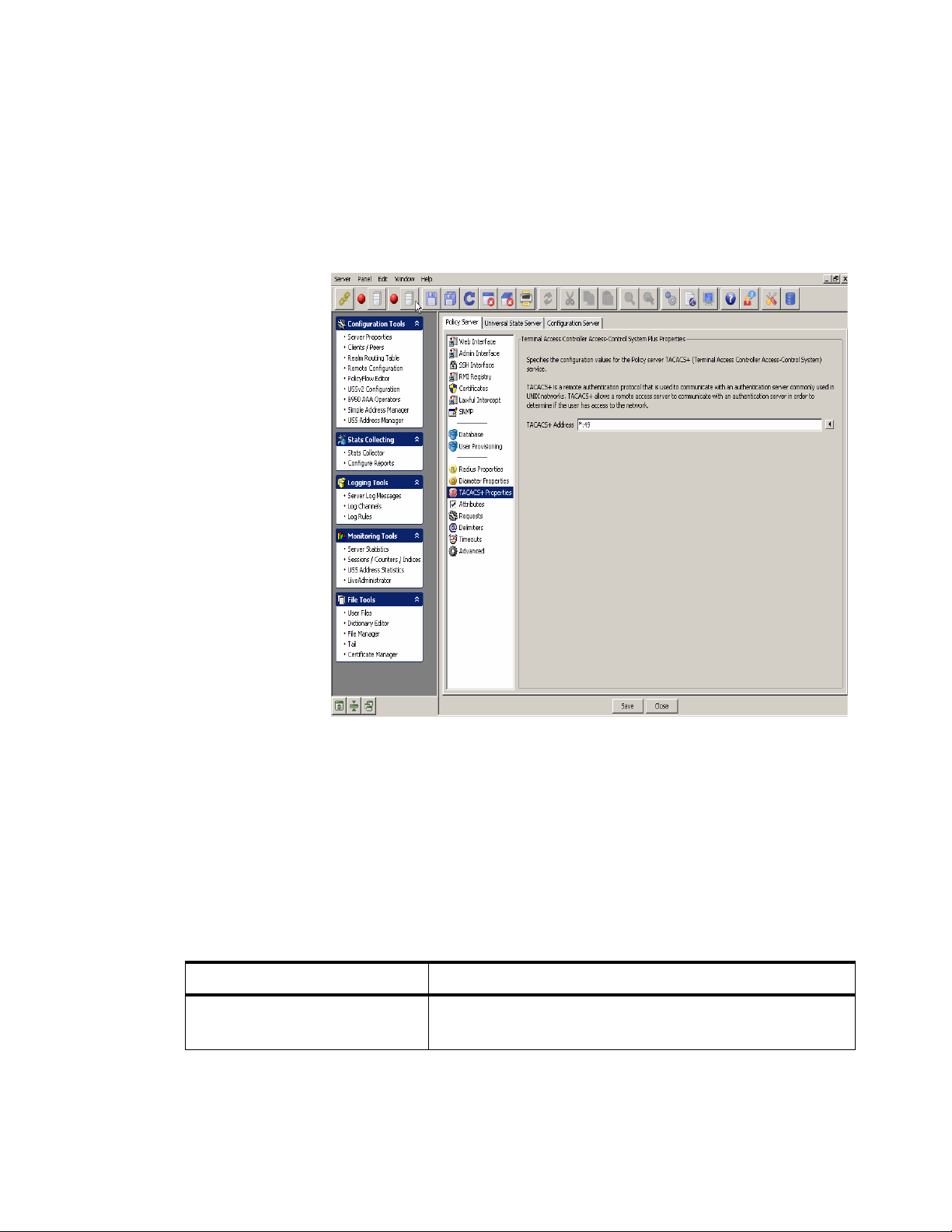
Policy Server tabManaging 8950 AAA Servers
............................................................................................................................................................................................................................................................
TACACS+ Properties Panel
To go to the TACACS+ Properties panel, click on the TACACS+ Properties option from
the Policy Server data pane menu options on the left side. The Terminal Access Controller
Access-Control System Plus Properties panel is displayed as shown in Figure 4-12.
Figure 4-12 Policy Server–Terminal Access Controller Access-Control System Plus
Properties Panel
The Terminal Access Controller Access-Control System Plus (TACACS+) Properties
panel specifies the configuration values for the policy server TACACS+ service.
TACACS+ is a remote authentication protocol that is used to communicate with an
authentication server commonly used in UNIX networks. TACACS+ allows a remote
access server to communicate with an authentication server in order to determine if the
user has access to the network.
Table 4-12 lists the configurable entities of this panel.
Table 4-12 TACACS+ Properties panel–Properties
Configurable Properties Description
TACACS+ Address Specifies the listener address that the policy server uses for
the TACACS+ service.
............................................................................................................................................................................................................................................................
4-20
365-360-001R6.0
Issue 1, December 2008
Page 77

Policy Serve r ta bManaging 8950 AAA Servers
............................................................................................................................................................................................................................................................
Attribute Properties Panel
To go to the Attribute Properties panel, click on the Attributes option from the Policy
Server data pane menu options on the left side. The Attribute Properties panel is displayed
as shown in Figure 4-13.
Figure 4-13 Policy Server–Attribute Properties Panel
The Attribute Properties panel specifies the configuration values that control how the
policy server handles RADIUS attributes. Place the mouse over each option to display
how it is used by the server.
Table 4-13 lists the configurable entities of this panel.
Table 4-13 Attribute Properties panel–Properties
Configurable Properties Description
Reveal Hidden Attributes Yes or No option. If enabled, attributes that are marked
as hidden in the dictionary are now displayed in the
packet trace.
Strict Attribute Encoding Yes or No option. If enabled, attributes that can’t be
encoded cause an exception. If not enabled attributes
that can’t be encoded are skipped and not sent.
............................................................................................................................................................................................................................................................
365-360-001R6.0
Issue 1, December 2008
4-21
Page 78

Policy Server tabManaging 8950 AAA Servers
............................................................................................................................................................................................................................................................
Requests Properties Panel
To go to the Requests Properties panel, click on the Requests option from the Policy
Server data pane menu options on the left side. The Radius Request Properties panel is
displayed as shown in Figure 4-14.
Figure 4-14 Policy Server–Radius Request Properties Panel
The Radius Request Properties panel specifies the configuration values that control how
the policy server handles RADIUS requests (packets). Place the mouse ov er each option to
display how it is used by the server.
Table 4-14 lists the configurable entities of this panel.
Table 4-14 Radius Request Properties panel–Properties
Configurable Properties Description
Automatically Check Items Yes or No option. If enabled, the policy server runs a
check item plug-in equiv a lent at the end of the method
chain.
Automatically Check Password Yes or No option. If enabled, the policy server checks
the password to the end of the method chain. This is
similar to the AuthLocal plug-in.
............................................................................................................................................................................................................................................................
4-22
365-360-001R6.0
Issue 1, December 2008
Page 79

Policy Serve r ta bManaging 8950 AAA Servers
............................................................................................................................................................................................................................................................
Table 4-14 Radius Request Properties panel–Properties
Configurable Properties Description
Automatically Check Leftovers Yes or No option. If enabled, the policy server rejects a
request if there are check items left to be checked.
Automatically Remove Check Items Yes or No option. If enabled, the policy server
removes check items as they are checked by plug-ins.
Delimiters Panel
To go to the User Name Parsing Delimiters panel, click on the Delimiters option from the
Policy Server data pane menu options on the left side. The User Name Parsing Delimiters
panel is displayed as shown in Figure 4-15.
Figure 4-15 Policy Server–User Name Parsing Delimiters Panel
Automatically Check Minimum
Session Timeout
Yes or No option. If enabled, the policy server
compares the minimum session timeout with the
Time-of-Day value to decide whether to accept the
request.
The policy server allows parsing of the User-Name attribute into the Base-Name and
Realm attributes.
............................................................................................................................................................................................................................................................
365-360-001R6.0
Issue 1, December 2008
4-23
Page 80

Policy Server tabManaging 8950 AAA Servers
............................................................................................................................................................................................................................................................
The first property below lists all valid delimiters to split the User-Name attribute. All
delimiters are evaluated in the order the y are entered. User-Name is searched character by
character from left to right for the match. The split is done on the first occurrence of the
delimiter.
Once a match is found, the second property is used to determine which part of the UserName attributes is the Base-Name and which part is the Realm. If you specified a
delimiter in the second property that was used to parse the User-Name, it is parsed as
<Base-Name>[Delimiter]<Realm>. If not, it is parsed as <Realm>[Delimiter]<BaseName>.
Table 4-15 lists the configurable entities of this panel.
Table 4-15 User Name Parsing Delimiters Panel–Properties
Configurable Properties Description
Realm delimiter characters List of characters in search order to parse the user name
into a user and realm. By default, the realm is the left
hand value and the user is the right hand value, unless
the delimiter is found in the ‘Delimiters for realm on
right side’ value. The default when not specified is ‘@’.
Delimiters for realm on right-hand
side
Timeout Properties Panel
To go to the Timeout Properties panel, click on the Timeouts option from the Policy
Server data pane menu options on the left side. The Timeout Properties panel is displayed
as shown in Figure 4-16.
List of characters that mean the realm is the right hand
value and the user is the left hand value of the parsed
user name. This list should be a subset of the Realm
Delimiter characters. The default when not specified is
‘@’.
............................................................................................................................................................................................................................................................
4-24
365-360-001R6.0
Issue 1, December 2008
Page 81
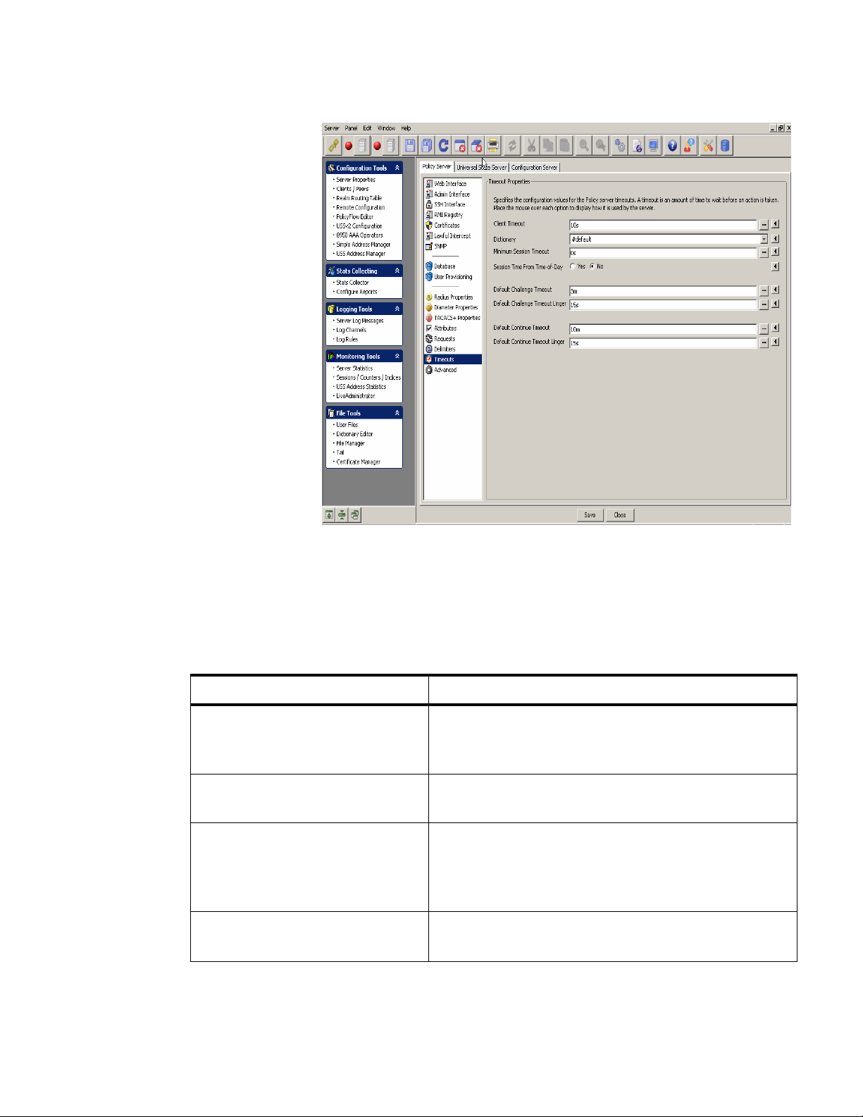
Policy Serve r ta bManaging 8950 AAA Servers
............................................................................................................................................................................................................................................................
Figure 4-16 Policy Server–Timeout Properties Panel
The Timeout properties panel specifies the configuration values for the Policy server
timeouts. A timeout is an amount of time to wait before an action is taken. Place the
mouse over each option to display how it is used by the server.
Table 4-16 lists the configurable entities of this panel.
Table 4-16 Timeout Properties Panel–Properties
Configurable Properties Description
Client Timeout Time, in milliseconds, to specify the amount of time the
policy server will wait before it discards the requests.
This should match the timeout set on your NAS client.
Dictionary Specifies the dictionary name to use for this client class
definition.
Minimum Session Timeout The policy server will reject any request that has a
session-time value less than the value specified by the
property . If reply.session-time is not set then no action is
needed.
Session Time from Time-of-Day If enabled, the session time is the time remaining from
the Time-of-Day check item.
............................................................................................................................................................................................................................................................
365-360-001R6.0
Issue 1, December 2008
4-25
Page 82

Policy Server tabManaging 8950 AAA Servers
............................................................................................................................................................................................................................................................
Table 4-16 Timeout Properties Panel–Properties
Configurable Properties Description
Default Challenge Timeout Default Challenge Timeout. Duration with default
timeunit in seconds.
Default Challenge Timeout Linger Default challenge timeout linger. Duration with default
timeunit in seconds.
Default Continue Timeout Default continue timeout. Duration with default timeunit
in seconds.
Default Continue Timeout Linger Default continue timeout linger. Duration with default
timeunit in seconds.
Advanced Properties Panel
To go to the Advanced Properties panel, click on the Advanced option from the Policy
Server data pane menu options on the left side. The Advanced Properties panel is
displayed as shown in Figure 4-17.
Figure 4-17 Policy Server–Advanced Properties Panel
The Advanced properties panel reflects the advanced configuration properties. In most
circumstances, you will not need to change these values.
............................................................................................................................................................................................................................................................
4-26
365-360-001R6.0
Issue 1, December 2008
Page 83

Policy Serve r ta bManaging 8950 AAA Servers
............................................................................................................................................................................................................................................................
Table 4-17 lists the configurable entities of this panel.
Table 4-17 Advanced Properties Panel–Properties
Configurable Properties Description
Max Plug-ins in Method Chains Specifies the maximum number of plug-in
invocations for ISPs. The default is 100.
Max number of waiting items Specifies the maximum number of RADIUS items
that can be waiting to be processed by the policy
server. The default is 0, which means no limit.
Important! Setting this to small numbers (for
example, less than 10) will greatly diminish server
performance.
TAOS Port Normalization Specifies how to get the real NAS port number out
of the NAS port info. This should only be used if
your NASs are running TAOS.
Character Set for Encoding Specifies the character set to use to encode string
attributes in requests.
Cache Data File Specifies the file that contains the ‘cache’ data
when using the ReadCache and WriteCache
plugins. If specified, the contents of the ‘cache’ is
written to this file on policy server shutdown and
read into the cache on policy server startup.
Cache NAS Routes Yes or No option. Specifies whether NAS IP
address and Client IP address (proxy) are stored in
the NAS Routes cache.
NAS Routes Cache Name Specifies the name of the cache to store NAS
Routes within the policy server.
Log By Item Yes or No option. If enabled, the policy server
groups all messages of a request together when the
messages are logged. If not enabled, messages from
different requests could overlap in the log output.
HTTP Total Connections Sets the maximum number of concurrent HTTP
connections to make as a client.
HTTP Connection Timeout Sets the timeout in milliseconds used when
retrieving an HTTP connection from the HTTP
connection manager. 0 means to wait indefinitely.
............................................................................................................................................................................................................................................................
365-360-001R6.0
Issue 1, December 2008
4-27
Page 84

Universal State Server tabManaging 8950 AAA Servers
............................................................................................................................................................................................................................................................
Table 4-17 Advanced Properties Panel–Properties
Configurable Properties Description
Send Error Ratio Sets a simulated transmit error ratio for server.
When set to a non-zero value, RADIUS packets
transmitted from the work engine will be randomly
dropped. If set to one, all packets will be dropped.
Receive Error Ratio Sets a simulated receive error ratio for server
RADIUS listeners. When set to a non-zero value,
RADIUS listener threads will randomly drop
received RADIUS packets. A v alue of one will drop
all packets.
Wire Decode Map Specifies how to read the request from the wire
(decode) into the policy server. If not specified,
‘${request.*}:=${*};’ is used.
Use an ‘@’ symbol to reference a file, example,
@filename.
Universal State Server tab
About the Universal State Server tab
The Universal State Server (USS) is an in-memory database optimized to track networkresource usage. It interacts with the 8950 AAA server to maintain usage counts and
enforce resource limits within the network.
The Universal State Server tab allows you to configure the entities in the Universal State
Server.
To go to the Universal State Server panel, click on the Universal State Server tab in the
Server Properties navigation option. The Uni versal State Server properties tab is displayed
as shown in Figure 4-18.
............................................................................................................................................................................................................................................................
4-28
365-360-001R6.0
Issue 1, December 2008
Page 85

Universal State Server tabManaging 8950 AAA Servers
............................................................................................................................................................................................................................................................
Figure 4-18 Universal State Server Properties Panel
USS Panel
When you click on the Universal State Server tab option, by default, the Universal State
Server properties panel is displayed as shown in Figure 4-18.
The Universal State Server properties panel specifies the configuration values for the
Universal State Server.
Table 4-18 lists the configurable entities of this panel.
Table 4-18 Universal State Server Panel–Properties
Configurable Properties Description
Accounting Start Timeout Specifies the time (in milliseconds) the Universal State
Server will wait for an accounting-start after recording
an access-accept for a particular port.
Session Timeout Specifies the time (in milliseconds) after which the
Universal State Server will mark a port as idle.
Inactive Timeout Specifies the time (in milliseconds) after which an
inactive session entry will be removed entirely. A value
of -1 disables the timeout and 0 fires immediately. The
default value is -1 (disabled).
............................................................................................................................................................................................................................................................
365-360-001R6.0
Issue 1, December 2008
4-29
Page 86

Universal State Server tabManaging 8950 AAA Servers
............................................................................................................................................................................................................................................................
Table 4-18 Universal State Server Panel–Properties
Configurable Properties Description
Key Separator Specifies the character that separates the key into two
parts for the creation of secondary indices. This
character should not appear in the values used to
construct the key (that is, the NAS-IP-Address and NASPort).
Session State Data File Specifies a file to store the session state information. If
specified, the state server saves the session information
when it shuts down. When the state server is restarted the
initial session information is read from this file.
Important! This file is deleted after read and created
each time the state server shuts down.
LDAP interface information–Specifies the configuration values for the LDAP interface for the
Universal State Server
LDAP Host Address Specifies the listener address that the po licy server uses
for the LDAP interface to the stateserver.
Replication Panel
To go to the Universal State Server Replication panel, click on the Replication option
from the Universal State Server data pane menu options on the left side.
The Universal State Server Replication panel has two tabs, the HA-USS tab and the
Advanced tab. By default, the HA-USS tab panel is displayed as shown in Figure 4-19.
............................................................................................................................................................................................................................................................
4-30
365-360-001R6.0
Issue 1, December 2008
Page 87

Universal State Server tabManaging 8950 AAA Servers
............................................................................................................................................................................................................................................................
Figure 4-19 Universal State Server Replication Panel with HA-USS tab
The HA-USS tab in the Universal State Server Replication panel specifies the values for
configuring the high-availability (replicated) universal state server (HA-USS).
Table 4-19 lists the configurable entities of this panel.
Table 4-19 Universal State Server Replication Panel–HA-USS tab properties
Configurable Properties Description
Replication Role Specifies the role of the stateserver on this server.
Primary Address Specifies the host and address of the state server (the
embedded registry). On the secondary , this sho uld be set
to the primary host name, and on the primary can be
either “localhost” or the primary host name. If a nondefault port is desired, specify it as localhost:9089.
Secondary Address Specifies the host and address of the state server (the
embedded registry) to use in an replicated USS Address
Manager configuration. On the primary, this should be
set to the secondary host name. If a non-default port is
desired, specify it as localhost:9089.
............................................................................................................................................................................................................................................................
365-360-001R6.0
Issue 1, December 2008
4-31
Page 88

Universal State Server tabManaging 8950 AAA Servers
............................................................................................................................................................................................................................................................
Table 4-19 Universal State Server Replication Panel–HA-USS tab properties
Configurable Properties Description
Use Secure Connections Yes or No option. Specifies to use secure connections
(SSL) for registry connections and communications
between the primary and secondary state servers.
Communication Interval Specifies how often (in milliseconds) that the state
server communicates with the primary state server.
Discovery Retries Specifies the number of times to attempt to find the
primary state server.
Discovery Retry Time Specifies the time (in milliseconds) to wait between
each failed attempt to find the primary state server.
Registry Timeout Specifies the maximum amount of time (in
milliseconds) to allow before a remote registry access
aborts the attempt.
Primary Hold Off time Specifies the amount of time (in milliseconds) that the
primary will wait to receive updates from the secondary.
This only occurs when the primary shuts down and is
restarted.
On the Universal State Server Replication panel, click on the Advanced tab. The
Advanced tab panel is displayed as shown in Figure 4-20.
............................................................................................................................................................................................................................................................
4-32
365-360-001R6.0
Issue 1, December 2008
Page 89

Universal State Server tabManaging 8950 AAA Servers
............................................................................................................................................................................................................................................................
Figure 4-20 Universal State Server Replication Panel with
Advanced tab
The Advanced tab in the Universal State Server Replication panel specifies the advanced
properties of the HA-USS. In most circumstances these properties will not need to be
changed.
Table 4-20 lists the configurable entities of this panel.
Table 4-20 Universal State Server Replication panel–Advanced tab properties
Configurable Properties Description
Minimum Update Threads Specifies the minimum number of worker
threads per replication update queue.
Maximum Update Threads Specifies the maximum number of worker
threads per replication update queue.
Maximum Update Push Specifies the maximum number of USS
entries to push to a secondary in a single
RMI call.
Maximum Secondary Fetch Specifies the maximum number of USS
entries for the primary to fetch from the
secondary in a single RMI call during
reconciliation.
............................................................................................................................................................................................................................................................
365-360-001R6.0
Issue 1, December 2008
4-33
Page 90

Universal State Server tabManaging 8950 AAA Servers
............................................................................................................................................................................................................................................................
Table 4-20 Universal State Server Replication panel–Advanced tab properties
Configurable Properties Description
Minimum Flow Entries Sets the minimum number of entries in the
primary replication queue before plug-in
flow control enables.
Entries per Millisecond Used to compute the flow control delay time
for the stateserver plug-in.
Attribute Counters Panel
To go to the Attribute Counters panel, click on the Attribute Counters option from the
Universal State Server panel me nu options on the left side. The Attribute Counters panel is
displayed as shown in Figure 4-21.
Figure 4-21 Universal State Server–Attribute Counters
The Attribute Counters panel specifies the list of attributes that the Universal State Server
counts. Each attribute is either counted when an authentication packet is recei v ed or when
an accounting start packet is received.
To specify that the attribute be counted at authentication, select Access as its type. Select
the type Accounting to count the attribute at accounting start.
............................................................................................................................................................................................................................................................
4-34
365-360-001R6.0
Issue 1, December 2008
Page 91

Universal State Server tabManaging 8950 AAA Servers
............................................................................................................................................................................................................................................................
A table is displayed that lists the attributes to count and specifies the type of the attribute.
Four action buttons are also displayed above the table that allows you to perform the
actions specified in Table 4-21.
Table 4-21 Universal State Server–Attribute Counters
Action Buttons Description
Inserts a record.
Edits the selected record.
Deletes the selected record.
Indices Panel
Deletes all the records.
To go to the Indices panel, click on the Indices option from the Universal State Server
panel menu options on the left side. The Indices panel is displayed as shown in
Figure 4-22.
............................................................................................................................................................................................................................................................
365-360-001R6.0
Issue 1, December 2008
4-35
Page 92
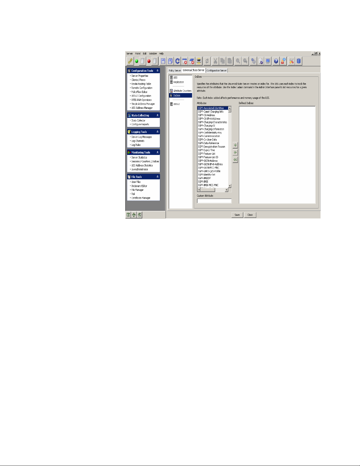
Universal State Server tabManaging 8950 AAA Servers
............................................................................................................................................................................................................................................................
Figure 4-22 Universal State Server–Indices
USSv2 panel
The Indices panel specifies the attributes that the Universal State Server creates an index
for. The USS uses each in dex to track the res ources of the attrib ute. Use the ‘inde x’ admin
command in the Admin Interface panel to list resources for a given attribute.
Important! Each index added affects the performance and memory usage of the
USS.
The Indices panel shows the existing Attrib utes in the Univ ersal State Server in one side of
the panel and allows you to select and add any of these attributes to the Defined Indices
window using the action arrow buttons in between these windows. You can choose to add
an item, delete selected record, or delete all records from the Defined Indices window.
To go to the State Server version 2 panel, click on the USSv2 option from the Universal
State Server data pane menu options on the left side. The State Server version 2 panel is
displayed as shown in Figure 4-23.
............................................................................................................................................................................................................................................................
4-36
365-360-001R6.0
Issue 1, December 2008
Page 93

Universal State Server tabManaging 8950 AAA Servers
............................................................................................................................................................................................................................................................
Figure 4-23 State Server version 2 Panel
The State Server version 2 panel specifies the values for configuring the version 2 of the
universal state server.
Table 4-22 lists the configurable entities of this panel.
Table 4-22 State Server version 2 panel properties
Configurable Properties Description
Replicated Server Timeout Specifies the amount of time the replication
queue is kept active after a replicated server has
gone down.
Heartbeat Time Specifies the amount of time between heartbeat
transmissions.
Heartbeat Skip Specifies the number of missing heartbeats
before a connection to a replicated server is
considered down.
Bucket Load Factor Specifies the maximum number of heartbeat
intervals of outstanding buckets before
replication is halted and a reconciliation is
prepared.
............................................................................................................................................................................................................................................................
365-360-001R6.0
Issue 1, December 2008
4-37
Page 94

Configuration Server tabManaging 8950 AAA Servers
............................................................................................................................................................................................................................................................
Table 4-22 State Server version 2 panel properties
Configurable Properties Description
Idle Ack Rate When remote ack rate per heartbeat interval
drops below this limit a prepared reconciliation
is started.
Merge Pool Size Specifies the number of threads servicing
inbound replication.
Replicator Pool Size Specifies the number of threads servicing
outbound replication.
Configuration Server tab
About the Configuration Server tab
The Configuration Server tab allows you to configure the entities in the Configuration
Server.
To go to the Configuration Server panel, click on the Configuration Server tab in the
Server Properties navigation option. The Configuration Serv er panel is displayed as shown
in Figure 4-24.
............................................................................................................................................................................................................................................................
4-38
365-360-001R6.0
Issue 1, December 2008
Page 95

Configuration Server tabManaging 8950 AAA Servers
............................................................................................................................................................................................................................................................
Figure 4-24 Configuration Server Panel
The Configuration Server panel specifies the properties used by the configuration server.
The configuration server is used by the Server Management Tool to configure a server
from a remote location. These properties are loaded each time the configuration server
starts. Any changes to these properties will take effect the next time you start the
configuration server and log into the SMT.
............................................................................................................................................................................................................................................................
365-360-001R6.0
Issue 1, December 2008
4-39
Page 96

Configuration Server tabManaging 8950 AAA Servers
............................................................................................................................................................................................................................................................
Table 4-23 lists the configurable entities of this panel.
Table 4-23 Configuration Server Panel properties
Configurable Properties Description
Administration Address Specifies the TCP/IP address on which the Admin interface
listens for connections. The address is in the form of a
hostname (or “*”) followed by a colon, followed by the port
number. The hostname must be a name that corresponds to a
local interface on the machine, or the value “*”, which
represents all local interfaces. The default value for this
property is “*.9020”.
SSH Address Specifies the address and port the server listens to, default is
“*:9021” and a port number of 0 means do not start SSH at all.
Registry Port Defines the port to be used when creating an RMI registry.
Normally, an RMI registry is already running at the address
specified. However, if there is no registry, the configuration
server will try to create one on the local host. By default, it
uses the RMI port 9097 to do this, but this property enables
another port to be used if necessary.
Secure Registry Port Secure registry port.
Log File Name Specifies the name of the file in which configuration server
writes messages and errors. The file ‘config.log’ is the default
log file name.
Level of Messages to Log Specifies the level (or deb ug le v el). The le vel determines what
type of messages the configuration server to the log file. By
default, the configuration server logs at ‘info’ level.
E ND OF STEPS
........................................................................................................................................................
............................................................................................................................................................................................................................................................
4-40
365-360-001R6.0
Issue 1, December 2008
Page 97

5 Configuring 8950 AAA
Client Properties
Overview
Purpose
This chapter discusses the process of configuring clients (NASs or other access points)
with the 8950 AAA Server Management Tool. Use the Clients panel to identify the clients
with whom your 8950 AAA server communicates during request processing. Refer to
your client product documentation for information specific to its configuration options.
The following topics are included in this chapter:
Configuring Clients 5-2
The Radius Clients tab 5-4
The Diameter Peers tab 5-8
The TACACS+ Clients tab 5-11
The Client Classes tab 5-14
Introduction
Upon receiving a RADIUS request, 8950 AAA must first determine that the request is
from an authorized RADIUS client. The source of the request is validated before the
request is accepted for processing. The server uses the source IP address or domain name
of the data packet to locate client information stored in a special 8950 AAA file called the
clients file. The clients file is maintained using the Clients panel of the SMT. Messages
from unknown clients are logged and then discarded.
............................................................................................................................................................................................................................................................
365-360-001R6.0
Issue 1, December 2008
5-1
Page 98

Configuring ClientsConfiguring 8950 AAA Client Properties
............................................................................................................................................................................................................................................................
Configuring Clients
About Configuring Clients
A RADIUS client (NAS or other resource with RADIUS client capabilities) passes session
information to designated RADIUS servers and acts on the response returned. The 8950
AAA server must have the following information for each client that sends RADIUS
requests to the server:
• IP address or domain name of the client
• A shared secret used between the server and the client
Important! Do not add entries for remote servers that will receive requests provided
from the 8950 AAA server unless requests are also received directly from this remote
server.
Using the SMT to Configure Clients
This section describes how to configure a 8950 AAA client. The specific procedure that
follows lists steps to modify an existing client using the Server Management Tool. For
information about running the SMT, please refer to “Starting the Server Management
Tool”.
1. Select Clients/Peers from the Configuration Tools folder on the Navigation pane, as
shown in Figure 5-1.
Figure 5-1 Navigation Pane–Clients/Peers option
The
Clients/Peers
option in the
Navigation pane
Result:
The 8950 AAA client/peer panel is displayed as shown in Figure 5-2.
............................................................................................................................................................................................................................................................
5-2
365-360-001R6.0
Issue 1, December 2008
Page 99

Configuring ClientsConfiguring 8950 AAA Client Properties
............................................................................................................................................................................................................................................................
Figure 5-2 The 8950 AAA SMT–Clients/Peers panel
The Clients/Peers panel (Figure 5-2) contains four tabs as following:
• Radius Clients
• Diameter Peers
• TACACS+ Clients
• Client Classes
When you click on the Clients/Peers in the navigation pane, by default, the Radius Clients
tab is displayed as showed in Figure 5-2. Click on the other tabs like the Diameter Peers
tab, the TACA CS+ Clients tab, and the Client Classes tab to display information related to
that screen. The following sections in this chapter explain each of these tabs in detail.
Using the Client/Peers SMT Action buttons
The Client/Peers menu bar also consists of a set of Action Buttons that appear at the top
of the 8950 AAA client/peer panel, as shown in Figure 5-2.
The Action buttons are as shown in Figure 5-3.
Figure 5-3 Client/Peers–Action buttons
You can perform the following actions using these action buttons:
• Insert a record
• Edit selected record
• Delete selected record
............................................................................................................................................................................................................................................................
365-360-001R6.0
Issue 1, December 2008
5-3
Page 100

The Radius Clients tabConfiguring 8950 AAA Client Properties
............................................................................................................................................................................................................................................................
• Delete all records
• Make a copy of selected record
• Move selected record up
• Move selected record down
You can perform any of the required actions using these action buttons.
The Radius Clients tab
Radius Clients tab
The Radius Clients tab displays information about Radius Clients in different columns.
Table 5-1 displays the Radius Clients tab information.
Table 5-1 Client/Peers SMT–Radius Clients tab information
Column Name Description
Client IP Address or Host The client IP address, host name, or Fully Qualified
Domain Name (FQDN).
Shared Secret The secret key shared between the 8950 AAA server
and the client. The shared secret must be entered
exactly the same way on both the 8950 AAA and the
client. Errors in entering the secret key is one of the
most common causes of 8950 AAA configuration
problems.
Client classes & Attributes This section shows the names of any Client Classes
to which this client has been assigned. In addition,
any properties (specific Attribute Value Pairs (AVPs)
assigned to the client are displayed. If it contains
#default then there are no assigned classes or
attributes for the client.
T o go to the Radius Client Pr operties panel, click on the action b utton. The Radius
Client Properties panel is displayed as shown in Figure 5-4. This panel allows you to add
or insert records to the Radius Client Properties. The Radius Client Properties panel, as
shown in Figure 5-4, has the following three tabs:
• The Radius Client Properties tab that allows to add a record.
• The Client Classes and Attributes tab that allows to select the required client option.
• The Comment tab that allows to enter necessary comments.
............................................................................................................................................................................................................................................................
5-4
365-360-001R6.0
Issue 1, December 2008
 Loading...