

Page 1

LCT TV
Service Manual
Page 2
-2 -
T
S
S
P
0
2
-
T
C
L
:
l
e
d
M
M
M
o
o
o
d
d
e
e
l
l
:
:
L
L
C
C
T
T
-
-
2
2
0
0
P
P
S
S
S
S
T
T
Model No.: LCT-20PSST
Version: 1.0
Page 3

-3 -
CONTENTS
SAFETY PRECAUTIONS....................................................................................................................... 4
ALIGNMENT INSTRUCTION............................................................................................................... 6
METHOD OF SOFTWARE UPGRADING ............................................................................................ 9
BLOCK DIAGRAM ..............................................................................................................................13
IC BLOCK DIAGRAM .........................................................................................................................14
WIRING DIAGRAM............................................................................................................................. 18
INDENTIFICATION CRITERIA FOR THE BRIGHT SPOT & DARK SPOT.................................... 19
TROUBLE SHOOTING ........................................................................................................................ 26
EXPLODED VIEW................................................................................................................................ 31
PART LIST............................................................................................................................................. 32
Model No.: LCT-20PSST
Version: 1.0
Page 4

-4 -
SAFETY PRECAUTIONS
1. Instructions
Be sure to switch off the power supply before replacing or welding any components or welding
any components or inserting /plugging in connection wire Anti static measures to be taken
(throughout the entire production process).
a. Do not touch here and there by hand at will
b. Be sure to use anti static electric iron
c. It’s a must for the welder to wear anti static gloves
Please refer to the detailed list before replacing components that have special safety requirements.
Do not change the specs and type at will.
2. Points for attention in servicing of LCD
a. Screens are different from one model to another and therefore not interchangeable. Be sure
to use the screen of the original model for replacement.
b. Operation voltage of LCD screen is 700-825V. Be sure to take proper measures in protecting
yourself and the machine when testing the system in the course of normal operation or right
after the power is witched off. Please do not touch the circuit or the metal part of the module
that is in operation mode. Relevant operation is possible only one minute after the power is
switched off.
c. Do not use any adapter that is not identical with the TV set. Otherwise it will cause fire or
damage to the set.
d. Never operate the set or do any installation work in bad environment such as wet bathroom,
laundry, kitchen or nearby fire source, heating equipment and devices or exposure to sunlight
etc. Otherwise bad effect will result.
e. If any foreign substance such as water, liquid, metal slices or other matters happens to fall
into the module, be sure to cut the power off immediately and do not move anything on the
module lest it should cause fire or electric shock due to contact with the high voltage or short
circuit.
f. Should there be smoke, abnormal smell or sound from the module, please shut the power off
at once. Likewise, if the screen is not working after the power is on or in the course of
operation, the power must be cut off immediately and no more operation is allowed under
the same condition.
g. Do not pull out or plug in the connection wire when the module is in operation or just after
the power is off because in this case relatively high voltage still remains in the capacitor of
the driving circuit. Please wait at least one minute before the pulling out or plugging in the
connection wire.
Model No.: LCT-20PSST
Version: 1.0
Page 5
-5 -
h. When operating or installing LCD please don’t subject the LCD components to bending,
twisting or extrusion, collision lest mishap should result.
i. As most of the circuitry in LCD TV set is composed of CMOS integrated circuits, it’s
necessary to pay attention to anti static. Before servicing LCD TV make sure to take anti
static measure and ensure full grounding for all the parts that have to be grounded.
j. There are lots of connection wires between parts behind the LCD screen. When servicing or
moving the set please take care not to touch or scratch them. Once they are damaged the
screen would be unable to work and no way to get it repaired.
k. Special care must be taken in transporting or handling it. Exquisite chock vibration may leas
to breakage of screen glass or damage to driving circuit. Therefore it must be packed in a
strong case before the transportation or handling.
l. For the storage make sure to put it in a place where the environment can be controlled so as
to prevent the temperature and humidity from exceeding the limits as specified in the manual.
For prolonged storage, it is necessary to house it in an anti-moisture bag and put them
altogether in one place. The ambient conditions are tabulated as follows:
o
Temperature Scope for operation 0 ~+50
Scope for storage -20 ~ +60oC
Humidity Scope for operation 20% ~ 85%
Scope for storage 10% ~ 90%
m. Display of a fixed picture for a long time may result in appearance of picture residue on the
screen, as commonly called “ghost shadow”. The extent of the residual picture varies with
the maker of LCD screen. This “ghost shadow” may remain in the picture for a period of
time (several minutes). But when operating it please avoid displaying still picture in high
brightness for a long time.
3. Points for attention during installation
a. The front panel of LCD screen is of glass. When installing it please make sure to put it in
place.
b. For service or installation it’s necessary to use specified screw lest it should damage the
screen.
c. Be sure to take anti dust measures. Any foreign substance that happens to fall down between
the screen and the glass will affect the receiving and viewing effect.
d. When dismantling or mounting the protective partition plate that is used for anti vibration
and insulation please take care to keep it in intactness so as to avoid hidden trouble.
e. Be sure to protect the cabinet from damage or scratch during service, dismantling or
mounting.
C
Model No.: LCT-20PSST
Version: 1.0
Page 6
-6 -
ALIGNMENT INSTRUCTION
1. Test equipment
PM5518 (Video signal generator)
K-7253 (VGA signal generator)
CA210 (White balancer)
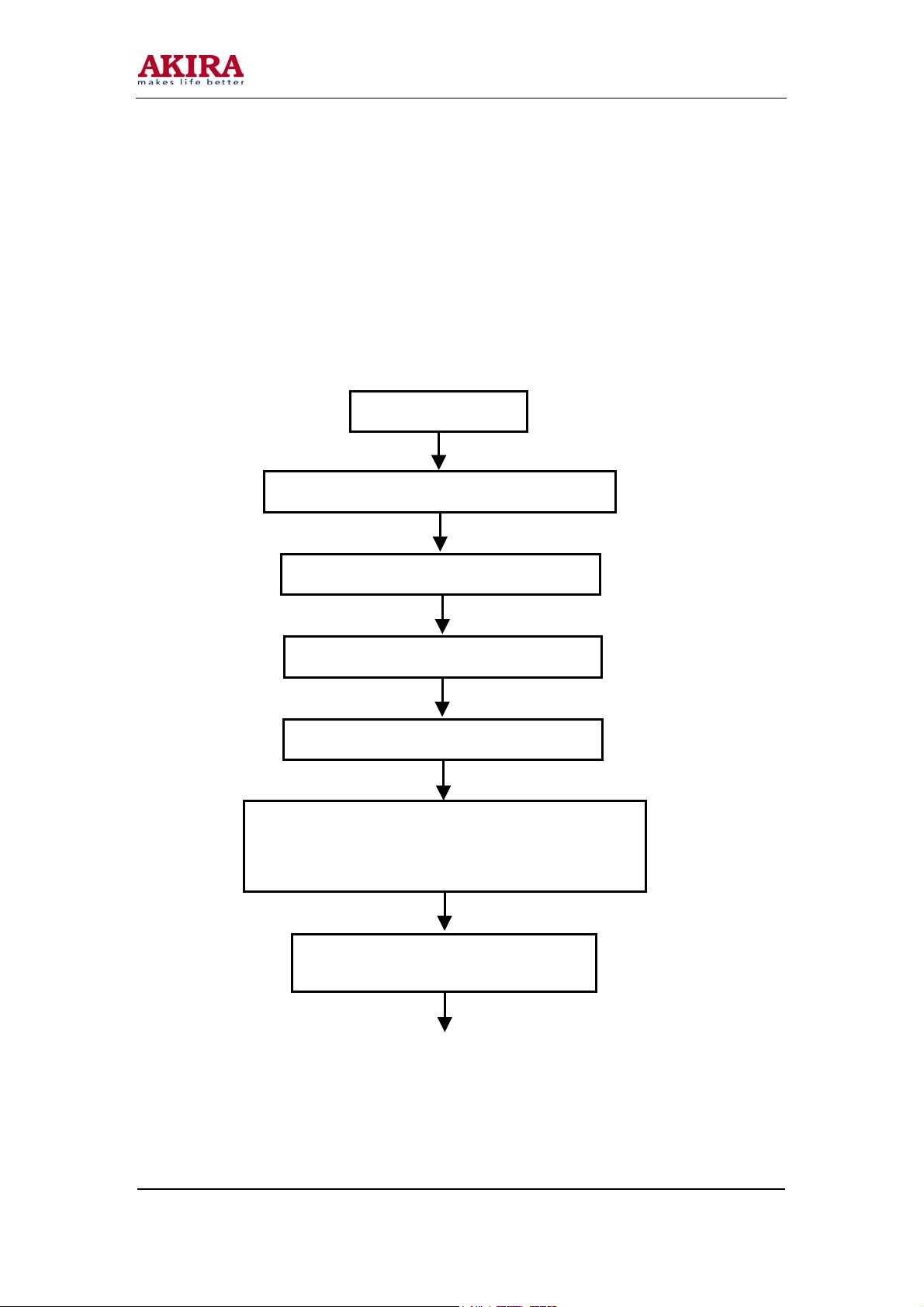
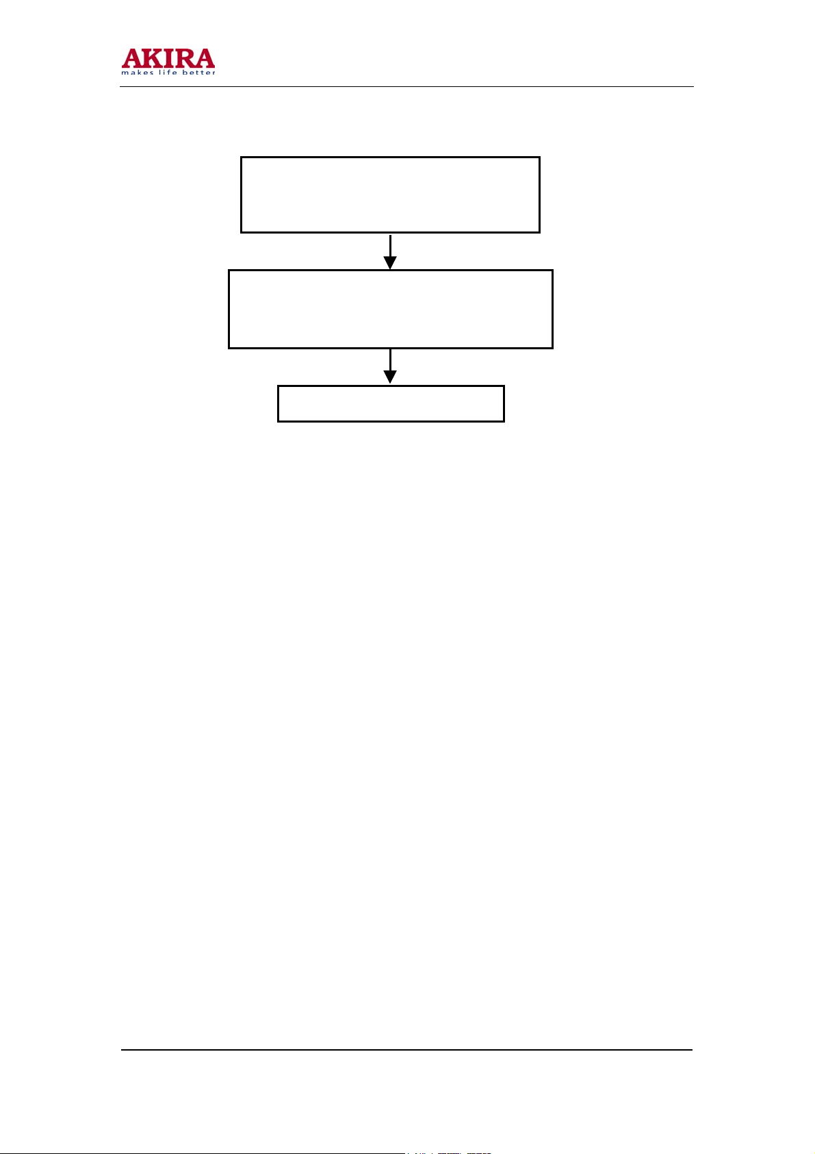
2. The alignment flow chart
Production of main board and TV board on the line
Check the main board and supply power board
Combined test for general assembly and aging
ADC correction and white balance adjustment
Connect to central signal source; check if various TV
functions (station skipping, modulate quantity control etc),
check if the output of earphone and speaker are normal
Input AV/S signal and HDTV signal; check
Written N101 and N304
various functions under AV/S terminal
Model No.: LCT-20PSST
Version: 1.0
Page 7
-7 -
3. Written program
Written program of IC(N101, N304)
4. Main board adjustment
a. According to wiring diagram, connect main board to supply power, the indicator to red.
b. Press the POWER button in the senor control, the indicator to blue.
c. Check the picture and sound is normal of TV /SCART /YPBPR /RGB /DVI channel.
5. Aging
a. Install the set.
b. Turn on the set, select the TV channel, then let the set no signal in state.
c. Aging one hour.
6. White balance
a. Enter RGB channel
b. Input grid signal (C_Hat_16x12(w)) of 60Hz of VGA terminal, resolution to 640 x 480 of in
optimum resolution. Adjust H-center and V-center, let to the picture normal.
c. Input gray (H)-16 signal, enter the factory menu, select “VGA AUTO COLOR”
d. Exit the factory menu, select the YPBPR /YCBCR channel.
e. Input the YPBPR signal, adjust different signal.
f. Input gray (H)-8 signal, using the CA-210 test the third level, adjust brightness and contrast,
let brightness to 180nit, enter factory menu, still the green color temperature value, adjust
blue color temperature and red color temperature, let to x = 0.28 ± 0.02, y = 0.299 ± 0.02.
Input VGA signal and check if display is normal
in the state of PC and various functions (analog
quantity control, line /field center etc.)
Input YpbPr /YcbCr signal, check the screen display is
normal in the various channel and various functions
(analog quantity control, line /field center etc.)
Check accessories and then packing
Model No.: LCT-20PSST
Version: 1.0
Page 8
-8 -
7. Performance inspection
a. TV function
Enter the search menu → auto search, connect RF-TV terminal to the central signal source,
check if there is station skipping.
b. AV /S input terminal
Input AV /S signal, check the picture and sound is normal.
c. VGA terminal
Input the VGA signal (table 1), and auto correction it, check the picture and sound is normal.
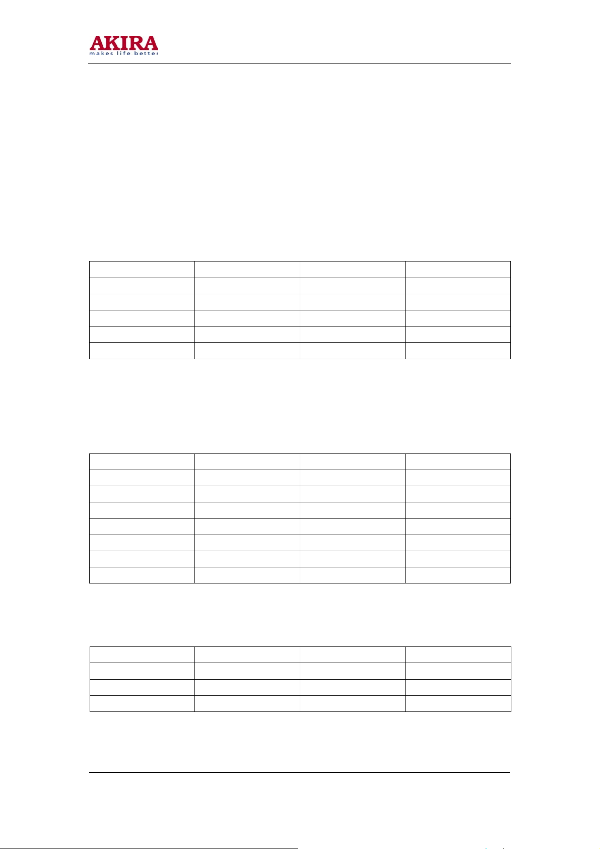
Table 1: VGA signal format
Resolution Pixel clock (MHz) H-SYNC (KHz) V-SYNC (Hz)
640 x 480 @ 60 25.175 31.469 59.900
640 x 480 @ 75 31.500 37.500 75.000
720 x 400 @ 70 28.322 31.469 70.086
800 x 600 @ 60 40.000 37.879 60.317
800 x 600 @ 75 49.500 46.875 75.000
d. YPBPR /YCBCR terminal
Input YPBPR /YCBCR signal (table 2) and auto correction it, check the picture and sound is
normal.
Table 2: YpbPr /YcbCr signal format
Resolution Pixel clock (MHz) H-SYNC (KHz) V-SYNC (Hz)
768 x 576 @ 50i 14.750 15.625 50
776 x 482 @ 60i 15.734 15.734 60
720 x 480 @ 60p 27.027 31.500 60
720 x 576 @ 50p 27.000 31.250 50
1280 x 720 @ 60p 74.250 45.000 60
1920 x 1080 @ 50i 74.250 28.125 50
1920 x 1080 @ 60i 74.250 33.750 60
e. For factory preset.
Table3: Factory preset
Item Factory Preset Item Factory Preset
Picture mode NATURE OSD language English
Sound mode User Color temperature Standard
Volume 30 Backlight 50
Model No.: LCT-20PSST
Version: 1.0
Page 9
-9 -
METHOD OF SOFTWARE UPGRADING
Step of software upgrading are as follows:
1. Using the parallel port wire and DVI transfer to VGA connection wire and then connect them by
an upgrade board.
2. Enter the factory menu, select upgrading item.
3. Connect main board to PC.
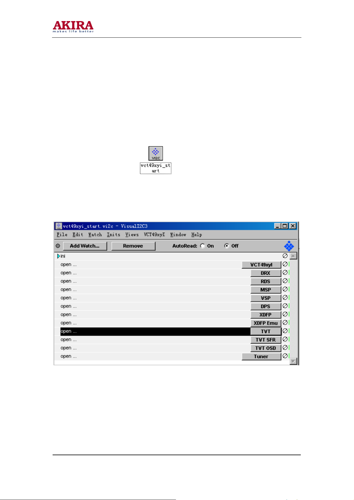
4. Operation the vct49xyi_start.exe display the software interface follow as:
Model No.: LCT-20PSST
Version: 1.0
Page 10
-10 -
5. Click the “TVT” item:
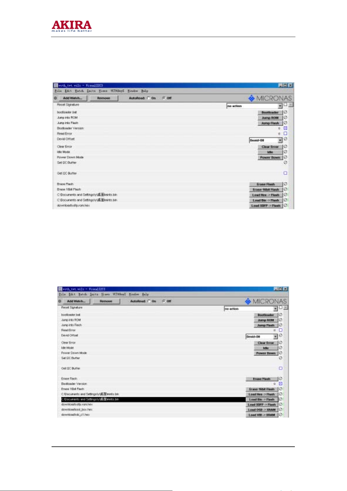
6. Click the BOOTLOADER button, display the DOS interface, after the interface disappear, click
the BOOTLAODER VERSION, if it value form 0 to 21, connecting is normal.
7. Click the ERASE 16 BIT FLASH, erasure the program. Click the BOOTLAODER VERSION, if
it value form 21 to 1, the program is erasure.
8. After erasure the program, click the black bar,
Model No.: LCT-20PSST
Version: 1.0
Page 11

-11 -
then display the interface, select the upgrade program.
After select the program, press the OK button, return the menu, click LOAS BIN-------- FLASH,
after the written the program is finish, the BAR disappear.
9. Turn off the power supply, return the set is over.
Note: Do not shut the power off or turn the TV set on during the FLASH write. Otherwise it may lead
to no way for flash to rewrite.
Model No.: LCT-20PSST
Version: 1.0
Page 12

-12 -
Working principle analysis of the unit
The set is multi-media LCD TV broadcast receiver, it contain PAL /SECAM B/G, I, D K L L’ of color
system and AV input, S-VHS input, PC, VGA, DVI and earphone output terminals. The power circuit
is built-in, it adopt the power manage chip STR-W6586N, output the 12v and 18v voltage, provide a
12V for the picture processing and 18V for sound amplifier. It is composed of the power board and
the video signal digital image processing.
VCT4993R (N102) is a integrative chip of digital IF amplifier, video decode, sound processing,
image processing and CPU, it has teletext decode function and 8M FLASH (N103) and 1M SRAM,
there can deposit 250 page teletext.
FR signal via the image IF signal of the tuner TUNER101, the signal is send to PIN109 and PIN110
of multi-system video /sound signal of N102 VCT4993 via Z103 of SAWF (Surface Acoustic Wave
Filter), IF signal is demodulated for image and sound, output a composite video signal, then select
switch signal source for video and s-video of AV board and RGB signal of SCART of the main board,
it send to digital image processing chip (MST519VA) via image processing (ITU656 of digital
signal).
After sound of DVI and YPBPR via switch selection N301 HEF4052, this signal and sound of the AV
and SCART, with sound of demodulation IF via internal switch selection and stereo processing from
PIN124 and PIN125 of VCT4993 (N102) output, then sent to sound amplifier (N504) of the power
board, it is amplified for speaker.
MST519VA (N202) is digital image processing chip, it process the YPBPR, VGA, DVI signal and the
ITU656 signal from VCT4993 (N102), though auto ADC correction and internal arithmetic
processing, then outputs 24 BIT TTL level RGB signal to socket X202. through N501 cable, the
signal is sent to LCD panel interface to perform reproduction of image.
Model No.: LCT-20PSST
Version: 1.0
Page 13

-13 -
BLOCK DIAGRAM
Model No.: LCT-20PSST
Version: 1.0
Page 14

-14 -
IC BLOCK DIAGRAM
1. VCT4993R
VCT4993R (N102) is a integrative chip of digital IF amplifier, video decode, sound processing,
image processing and CPU, it has teletext decode function and 8M FLASH (N103) and 1M
SRAM, there can deposit 250 page teletext. It has 10 VIDEO input, 3 VIDEO output. 3 SOUND
input and output, analog RGB output, ITU656 of digital signal output.
Figure 1-1: VCT4993R internal block diagram
Model No.: LCT-20PSST
Version: 1.0
Page 15

-15 -
VCT4993R PIN instructions:
PIN Function PIN Function
41 SDA_M 78 656102
42 SCL_M 78 656101
44 CSZ 79 656100
45 SCART_SWITCH 80 AUDIO_SEL_1
47 IR 81 AUDIO_SEL_0
48 MUTE 82 656CLK
50 INT 97 BKLON
58 VOUT2 98 STANDBY
60 VIN1 109 IF IN+
62 Y_IN 110 IF IN-
63 C_IN 112 TAGC
66 SCART_CVBS 113 AIN1R
67 SCART_R 114 AIN1L
68 SCART_G 115 AIN2R
69 SCART_B 116 AIN2L
70 FBL 117 AIN3R
71 656107 118 AIN3L
72 656106 122 AOUT1R
73 656105 123 AOUT1L
74 656104 124 SAPEAKEAR
77 656103 125 SAPEAKEAL
2. MST518 digital image processing
MST519VA (N202) is digital image processing chip, it process the YPBPR, VGA, DVI signal
and the ITU656 signal from VCT4993 (N102), through auto ADC correction and internal
arithmetic processing, then outputs 24 BIT TTL level RGB signal to socket X202. Through N501
cable, the signal is sent to LCD panel interface to perform reproduction of image.
Model No.: LCT-20PSST
Version: 1.0
Page 16

-16 -
MST518 PIN instructions:
Pin Function Pin Function Pin Function
43 DVI_IN R+ 65 VGA RIN 83 SDA_M
44 DVI_IN R- 63 VGA GIN 33 RESET
46 DVI_IN G+ 60 VGA BIN 85 INT
47 DVI_IN G- 40 HSYNC 86 PWM
49 DVI_IN B+ 41 VSYNC 87 LCDON
50 DVI_IN B- 75 CRIN 90 656 CLK
52 DVI_IN CLK+ 72 YIN 91-98 656100-656107
53 DVI_IN CLK- 70 CBIN 103-110 BA()-BA(7)
30 DVI_IN
DDC_SCL
29 DVI_IN
DDC_SDA
34 XIN 143 HSYNC
35 XOUT 144 VSYNC
Figure1-2: MST518 internal block diagram
Analog RGB0
Analog RGB1
HSYNC/VSYNC
Model No.: LCT-20PSST
Version: 1.0
Analog
DVI
Video Port
Dual
Interfac e
Engine
ITU656
82 SCZ 131-138 RA(0)-RA(7)
84 SCL_M 115-120
127-128
Display
Processing
Engine
HOST
interfac e
MCU XTAL/EXT CLK
OSD
Clock
Gen
GA()-GA(7)
Multi-F o r mat
Panel
Interface
To Panel
Page 17

-17 -
3. STR-W6856N switch adjustment IC
Figure 1-3: STR-W6856N internal block diagram
4. AN7522: dual-channel single-end push and pull audio power amplifier (10Wtyp)
Figure 1-4: AN7522 internal block diagram
AN7522 PINS instruction
Pin Function Pin Function Pin Function
2, 5 Input 8 MUTE 9 GND (output)
7, 12 Output 4 GND (input) 10 VCC
Model No.: LCT-20PSST
Version: 1.0
Page 18

-18 -
WIRING DIAGRAM
Model No.: LCT-20PSST
Version: 1.0
Page 19

-19 -
IDENTIFICATION CRITERIA FOR THE BRIGHT SPOT
AND DARK SPOT
Category Criteria
Quantity allowed Distance between two spots
One single
spot
Bright
spot
Dark
spots
Total defected point ≤7
Notes:
1. Definition of defected point (bright spot, dark spot): It is identified as a defected point if its area
exceeds ½ of a single picture element (R, G, B).
2. Definition of bright spot: It is identified as a bright spot if it is bright in the state of dark field and
its bright size remains unchanged.
3. Definition of dark spot: It is identified as a dark spot if it is dark in the state of while field and it
dark size remains unchanged.
4. Definition of two neighboring points: Defect of a group of picture elements (RB, RG, GB).
Model No.: LCT-20PSST
Version: 1.0
Two
neighboring
spots
Total No. ≤2
One single
spot
Two
neighboring
spots
Total No. ≤7
≤2
≤1
≤7
≤2
≥15mm
≥10mm
Page 20

-20 -
TROUBLE SHOOTING
1. Fault clearance
Before servicing please check to find the possible causes of the troubles according to the table
below.
a. Antenna (signal):
Symptoms Possible cause
Picture is out of focus or
jumping
Fringe in picture Check if the antenna is correctly oriented
Picture is interfered by stripe
shaped bright spots
There appear streaks or light
color on the screen
Bad status in signal receiving
Poor signal
Check if there is failure with the electrical connector
or the antenna.
Check if the antenna is properly connected.
Maybe there is electric wave reflected from hilltop or
building.
Possibly due to interference from automobile, train,
high voltage transmission line, neon lamp etc.
Maybe there is interference between antenna and
power supply line. Please try to separate them in a
longer distance.
Maybe the shielded-layer of signal wire is not
connected properly to the connector.
Check if interfered by other equipment and if
interfered possibly by the equipment like transmitting
antenna, non-professional radio station and cellular
phone.
Model No.: LCT-20PSST
Version: 1.0
Page 21

-21 -
b. TV set:
Symptoms Possible cause
Unable to switch the power
on
No picture and sound Check to see if the power supply of liquid crystal TV
Deterioration of color phase
or color tone
Screen position or size is not
proper
Picture is twisted and
deformed
Picture color changed or
colorless
Picture too bright and there is
distortion in the brightest area
Picture is whitish or too bright
in the darkest of the picture
No picture or signal produced
from the displayer is “XXX in
search” appears
There appears an indication-
“outside the receivable scope)
Model No.: LCT-20PSST
Version: 1.0
Check to see if the power plug has been inserted
properly into the socket.
has been switched on. (As can be indicated by the red
LED at the front of the TV set).
See if it’s receiving the signal that is transmitted from
other source than the station.
Check if it’s connected to the wrong terminal or if the
input mode is correct.
Check if the signal cable connection between video
frequency source and the liquid crystal TV set is
correct.
Check if all the picture setups have been corrected.
Check is the screen position and size is correctly set
up.
Check to see if the picture-frame ratio is properly set
up.
Check the “Components” or “RGB” settings of the
liquid crystal TV set and make proper adjustment
according to the signal types.
Check if the contrast setting is too high.
Possibly the output quality of DVD broadcaster is set
too high.
It maybe also due to improper terminal connection of
the video frequency signal in a certain position of the
system.
Check if the setting for the brightness is too high.
Possibly the brightness grade of DVD player
(broadcaster) is set too high.
Check if the cable is disconnected.
Check if it’s connected to the proper terminal or if the
input mode is correct.
Check if the TV set can receive input signal. The
signal is not correctly identified and VGA format is
beyond the specified scope.
Page 22

-22 -
Symptoms Possible cause
Remote control cannot work
properly
No picture and sound but only
hash
Blur picture Check if the antenna cable is correctly connected.
No sound Check if the “mute” audio frequency setting is
When playing VHS picture
search tape, there are lines at
the top or bottom of the
picture
Check if the batteries are installed in the reverse order.
Check if the battery is effective.
Check the distance or angle from the monitor.
Check if there is any obstruct between the remote
control and the TV set.
Check if the remote control signal-receiving window
is exposed to strong fluorescence.
Check if the antenna cable is correctly connected, or if
it has received the video signal correctly.
Of if it has received the right video signal.
selected.
Check if the sound volume is set to minimum.
Make sure the earphone is not connected.
Check if the cable connection is loose.
When being played or in pause VHS picture search
tape sometimes can’t provide stable picture, which
may lead to incorrect display of the liquid crystal TV.
In this case please press “auto” key on the remote
control so as to enable the liquid crystal TV set to
recheck the signal and then to display correct picture
signal.
Model No.: LCT-20PSST
Version: 1.0
Page 23

-23 -
N
N N
N
2. Trouble shooting guide
a. No raster, no picture and no sound
When the main power is turned on, the unit’s indicator light up in red (red indicator is
controlled by +3.3VSTANDBY), use the remote control or the unit’s STANDBY to lights up
the blue indicator.
Whether the IR
board’s red indicator
light up?
Whether the blue
indicator lights up
when press the
STANDBY button?
Whether the backlight
Whether the backlight
power or PBIAS pin
Check power circuit or whether the
VCT4993I PBIAS signal is normal
Y
Y
lights up?
is normal
Y
Power board’s +3.3V
is abnormal
Confirm the IR
sensor and its power
supply is normal
Whether the voltage
of the panel is
Y
Backlight board damage or protection.
Y
Y
normal?
Replace the backlight board
Indicator damages or
blue indicator +5V
power is abnormal
(check +5V circuit)
MST519 is normal
without signal output
or the output signal is
abnormal
Model No.: LCT-20PSST
Version: 1.0
Page 24

-24 -
y
N N
b. With picture and without sound when turning on
Increase the volume;
check whether every
channel has no sound
Check whether the
signal output by
VCT4993(IC) is
Sound amplifier or
peripheral circuit
does not work
c. When receiving TV signal, there is no picture or dark snow
Confirm the +5V, +32V power supply of TUNER. If they are normal, check whether
peripheral circuit of the TUNER or IF amplifier is normal. If they are all no problem, then
VCT4993 or its input signal is abnormal.
Y
normal
Y
normall
Check sound channel
of VGA and YPBPR
is normal
VCT4993 (IC) or peripheral
circuit does not work
normally
Model No.: LCT-20PSST
Version: 1.0
Page 25

-25 -
b
b
N
p
N
N
N N N N N
d. The power board trouble shooting guide
Power board
damages or fuse
Y
lows
Check whether
C512 has 18V
Check whether
in1 of N501 has
wave
Check whether
502 is damaged
Check whether
N505, D507 is
damaged
Replace the
damaged parts
Replace the fuse and check
Y
whether N501, D501
reakdown
Y
Replace D502
Y
Y
Replace N502
Check whether
N505 is damaged
Y
Replace
501, D501
Y
Replace
505
Model No.: LCT-20PSST
Version: 1.0
Page 26

CIRCUIT DIAGRAM
-26 -
Model No.: LCT-20PSST
Version: 1.0
Page 27

-27 -
Model No.: LCT-20PSST
Version: 1.0
Page 28

-28 -
Model No.: LCT-20PSST
Version: 1.0
Page 29

-29 -
Model No.: LCT-20PSST
Version: 1.0
Page 30

-30 -
Model No.: LCT-20PSST
Version: 1.0
Page 31

 Loading...