

Page 1

MINI HIFI
MICRO COMPONENT SYSTEM
Model:
QX3700
SERVICE MANUAL
www.akai.ru
Page 2
SERVICE MANUAL
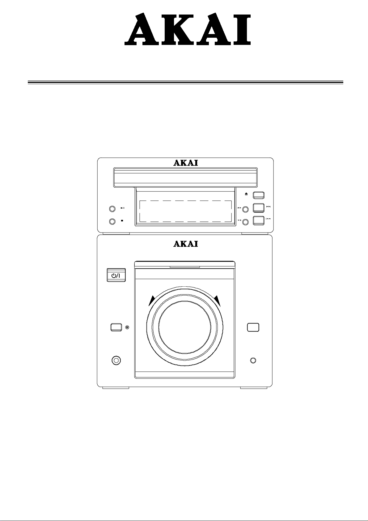
Mini Hi-Fi Micro Component System
Hi-Fi MICRO COMPONENT SYSTEM
STANDBY/ON
LOUDNESS
PHONES
VOLUME
QX-3700QX-3700
QX-3700
QX-3700QX-3700
UP/RDOWN/L
REMOTE
FUNCTION
Page 3

Contents
I. Safety instructions................................................................................................................. 2
II. Specifications...................................................................................................................... 3
III. Level List of Equipments & Instruments Required for Production.......................................... 6
IV. Block diagram .................................................................................................................... 7
V. Wiring diagram ................................................................................................................... 8
VI. Schematic Diagram ..........................................................................................................9
VII. Component Diagrams..................................................................................................... 10
VIII. Exploded Diagram View and Parts List .......................................................................... 18
This manual is the latest at the time of printing, and does not include
the modification which may be made after the printing, by the
constant improvement of product.
- 1 -
Page 4
I. Safety instructions
When using electric products, basic precautions should always
be followed, including the following:
1. Read Instructions – All the safety and operating instructions
should be read before the appliance is operated.
2. Retain Instructions – The safety and operating instructions
should be retained for future reference.
3. Heed Warnings – Adhere to all warnings on the appliance
and in the operating instructions.
4. Follow Instructions – All operating and use instructions
should be followed.
5. Water and Moisture – The appliance should not be used near
water-for example, near a bathtub, wash-bowl, kitchen sink,
laundry tub, in a wet basement, or near a swimming pool, etc.
6. Carts and Stands – The appliance should be used only with
a cart or stand that is recommended by the
manufacturer. An appliance and cart
combination should be moved with
care. Quick stops, excessive force,
and uneven surfaces may cause the
appliance and cart combination to
overturn.
7. Wall or Ceiling Mounting – The appliance should be mounted
to a wall or ceiling only as recommended by the manufacturer.
8. Ventilation – The appliance should be situated so that its lo
cation or position does not interfere with its proper ventilation.
For example, the appliance should not be situated on a bed,
sofa, rug or similar surface that may block the ventilation openings; or placed in a built-in installation, such as a bookcase or
cabinet that may impede the flow of air through the ventilation
openings.
9. Heat – The appliance should be situated away from heat
sources such as radiators, heat registers, stoves, or other ap
pliance (including amplifier) which produce heat.
10. Nonuse Periods – The power cord of the appliance should
be unplugged from the outlet when left unused for a long pe
riod of time.
11. Power Sources – The appliance should be connected to
a power supply only of the type described in the operating
instructions or as marked on the appliance.
12. Power Lines – An outdoor antenna should be located away
from power lines.
13. Power Cord Protection – Power-supply cords should be
routed so that they are not likely to be walked on or pinched
by items placed upon or against them, paying particular attention to cords, at plugs, convenience receptacles, and the point
where they exit from the appliance.
14. Power requirements for multi voltage (not for all mod
els) – Before connecting the power cord, make sure that the
voltage selector on the rear panel is set to the correct voltage
for you area. If not, please set it correctly.
15. Load – For protecting the appliance from being damaged, rated
load while is printed on the appliance or is explained in operation instruction, that should be connected to the speaker output of the appliance. Never short circuit the speaker output of
the appliance when the appliance is working.
16. Object and Liquid Entry – Care should be taken so that
objects do not fall and liquids are not spilled into the enclosure
through openings.
17. Cleaning – Unplug the appliance from the wall outlet before
cleaning. Do not use liquid cleaners or aerosol cleaner. Use a
damp cloth for cleaning.
18. Make your contribution to protect the environment –
Used batteries with the ISO symbol for recycling as well as
small accumulators (rechargeable batteries),
mini-batteries (cells) and starter
batteries should not be thrown into
the garbage can. Please leave them
at an appropriate depot.
Portable cart warning
19. Overloading – Do not overload wall outlets and extension
cords as this can result in a risk of fire or electric shock.
20. Damage Requiring Service – Unplug this appliance from the
wall outlet and refer servicing to qualified service personnel
under the following conditions:
a). The power-supply cord or the plug has been damaged;
b). Objects have been fallen, or liquid has been spilled into
the appliance;
c) . The appliance has been exposed to rain;
d) . The appliance does not appear to operate normally or ex-
hibits a marked change in performance;
e). The appliance has been dropped, or the enclosure dam
aged.
WARNING
TO REDUCE THE RISK OF FIRE OR ELECTRIC SHOCK, DO
NOT EXPOSE THIS APPLIANCE TO RAIN OR MOISTURE.
CAUTION
RISK OF ELECTRIC SHOCK
DO NOT OPEN
CAUTION
TO REDUCE THE RISK OF ELECTRIC SHOCK, DO NOT
REMOVE COVER (OR BACK). NO USER SERVICEABLE
P ARTS INSIDE. REFER SERVICING T O QUALIFIED SERVICE
PERSONNEL.
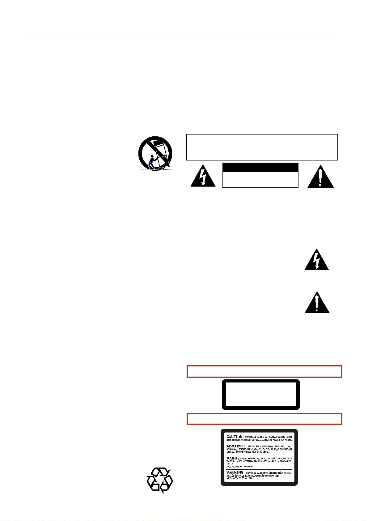
The lightning flash with arrowhead symbol,
within an equilateral triangle, is intended to
alert the user to the presence of uninsulated
“dangerous voltage” within the product’s
enclosure; that may be of sufficient magnitude
to constitute a risk of electric shock to persons.
The exclamation point within an equilateral
triangle is intended to alert the user to the
presence of important operating and
maintenance (servicing) instructions in the
literature accompanying the appliance.
CLASS 1 LASER PRODUCT
This product contains a low power laser device. To ensure
continued safety, do not remove any covers or attempt to gain
access to the inside of the product. Refer any servicing to qualified
personnel.
A. CLASSIFICATION LABEL, PLACED ON EXTERIOR SURFACE
CLASS 1 LASER PRODUCT
KLASSE 1 LASER PRODUKT
LUOKAN 1 LASER LAITE
KLASS 1 LASER AP PARAT
B. WARNING LABEL, PLACED INSIDE THE UNIT
- 2 -
Page 5
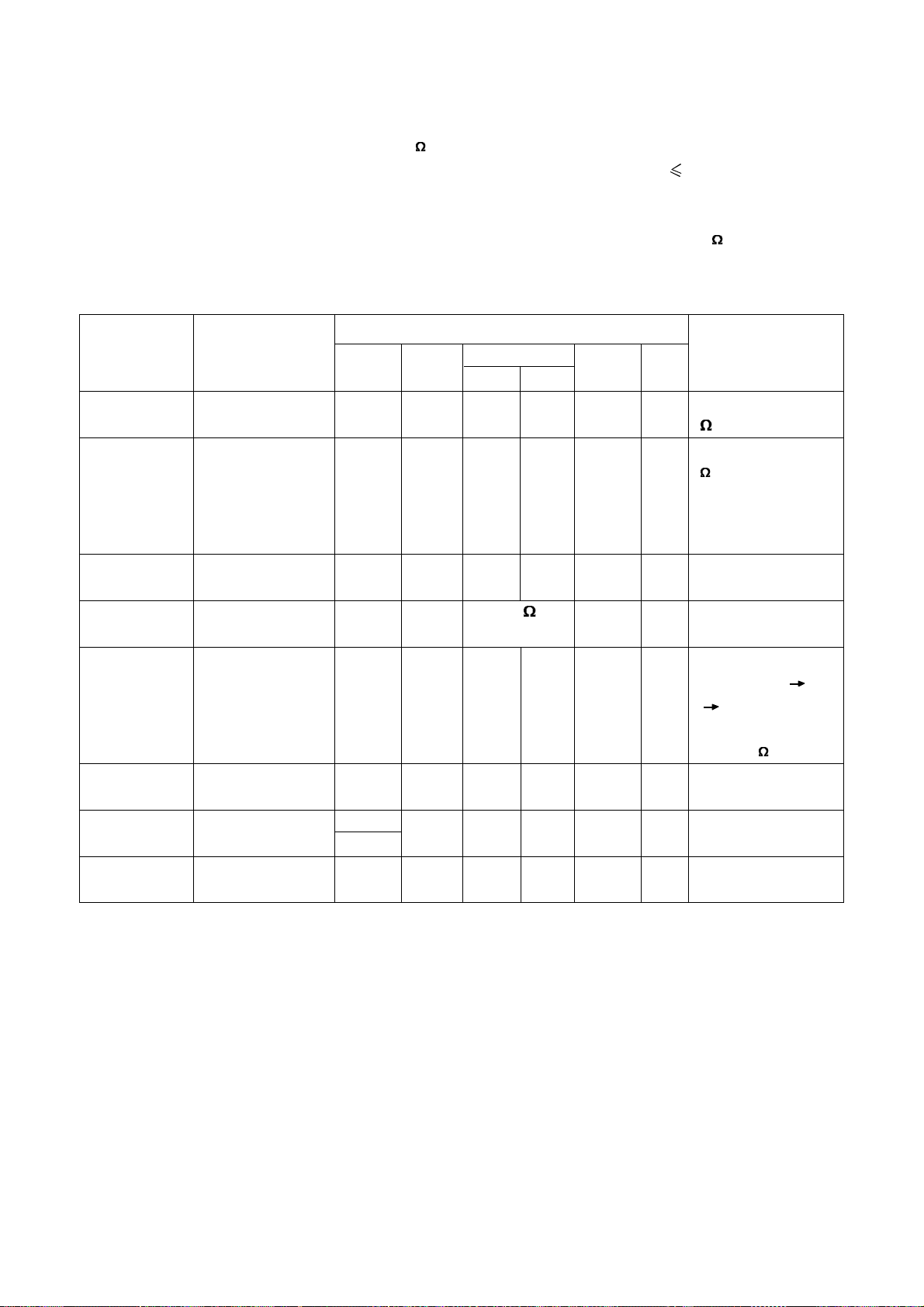
II. Specifications
CONDITIONS OF SPECIFICATION MEASUREMENTS
1. STANDARDS ENVIRONMENTAL CONDITIONS
TEMPERATURE : 23°C
HUMIDITY : 65%
IF NO DOUBT ARISES IN THE JUDEMENT, THE MEASUREMENT CAN BE MADE UNDER
CONDITIONS OF TEMPERATURE 10 TO 35°C AND HUMIDITY 45 TO 85%.
2. REATED POWER SUPPLY AC: 220V 50Hz
3. LOAD IMPEDANCE
SPEAKER OUTPUT : RESISTIVE LOAD AS SPECIFIED.(4 OHM)
PREAMPLIFIER OUTPUT AND RECORDING OUTPUT : 47k OHM RESISTOR (± 5%)
VIDEO OUTPUT: 75 OHM
4. STANDARD OPERATING CONDITION AND METHOD OF MEASUREMENT
a) OPERATION METHOD, SETTING POSITION OF THE UNIT STARTING CONDITION
FOR THE MEASUREMENT SHOULD BE MAINTAINED FOR TESTS OF AMPLIFIER
SECTION AS EIA-RS-490, FOR TEST OF TUNER SECTION AS IHF-T-200.
b) EXCEPT AS OTHERWISE SPECIFIED HEREIN, ALL TESTS SHALL BE MEASURED AT
FRONT CHANNELS AND SET THE SELECTOR POSITION.
MEASURED MODE
c) MODULATION OF FM DODE 75KHz DEVIATION AUDIO 1KHz 75 OHM
d) MODULATION OF FM STEREO MPX. 67.5KHz DEVIATION
7.5KHz PILOT
AUDIO 1 KHz
e) MODULATION OF MW 30% MOD. AUDIO 1KHz
f) REF. OUTPUT LINE OUT
Specifications
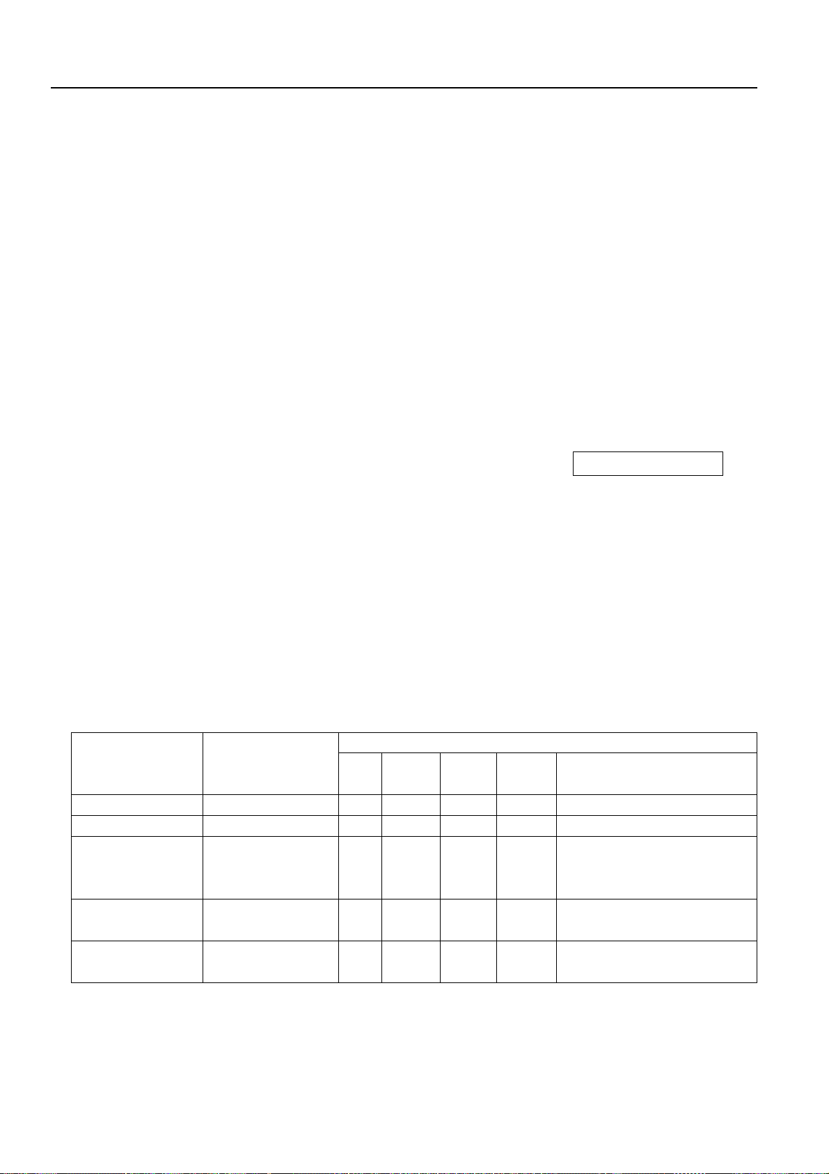
1. FM Section
FM Electrical Specifications (Text Point at Line Out)
Measurement Specifications Measurement Condition/Method/Remarks
Description 1HF FM Measu. SSG Others
BPF MODE Freq. Level
FM RANGE 87MHz~108MHz
30dB S/N ≤20uV Mono 98MHz Adjust
AUTO STOP 30±5dBuV Auto 98MHz Adjust Output level ratio of modulation
SENSITIVITY OFF to ON Pilot : ON, R ch :
ON
OUTPUT LEVEL 0.50±0.1Vrms Yes Mono 98MHz 60dBu Measure both channel test
point at Line Out
STEREO ≥20dB Yes Auto 98MHz 60dBu
SEPARATION
- 3 -
Page 6
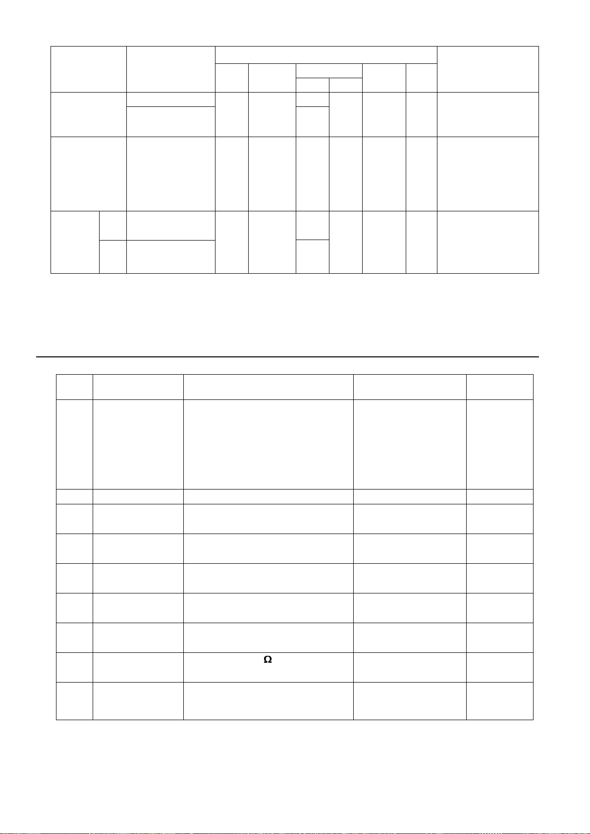
2. MW Section
i. MW Measurement Condition
(a) Antenna Input : Loop Antenna
(b) Measurement Frequency : Lower Center Upper
All versoin 603kHz 1008kHz 1404kHz (In case of no comment, measure at
center frequency.)
(c) Modulation Frequency : In case of no comment, use 1kHz 30% modulation
(e) Selectivity : Arithmetical mean of 2 values at ±10kHz deviated frequency
(f) Measurement Point : Test Point (At line out)
ii. MW Electrical Specifications
Measurement Specifications Measurement Condition/Method/Remarks
Description Meas.Freq. SG Level Others
AM RANGE 522KHz~1611KHz
26dB S/N ≤5.0mV/M Center Adjust Output level ratio of
modulation OFF to ON
AUTO STOP 20mV/M Center Adjust Minimum input level of Auto Stop
SENSITIVITY ≤Auto Stop Sensitivity threshold
≤5.0mV/M
OUTPUT LEVEL 150-500MVrms Center 10mV/M Measure both channel test point
at Line Out
3. VCD Section
VCD Measurement Condition
Measurement Point: At line out or video out
1. Electrical Specifications
No. Test Item Unit Specification
1 Video Output Level Vp-p 1.0±0.2
2 Audio Output Level Vrms 2.0+0.2/-1.0
3 Audio of Resp (20Hz~20KHz) dB ≤±3.5
4 Audio S/N (A-WTD) dB ≥70
5 Distortion & Noise (1KHz) dB ≤-50
6 Cross Talk L-R (Fundamental) dB ≥60
2. Mechanical Specifications
No. Test Item Unit Specification
1 Reading Time S <20 (S)
2 Ball Bound:
Drop 8g Super Ball from 3cm Height No AV Noise
- 4 -
Page 7
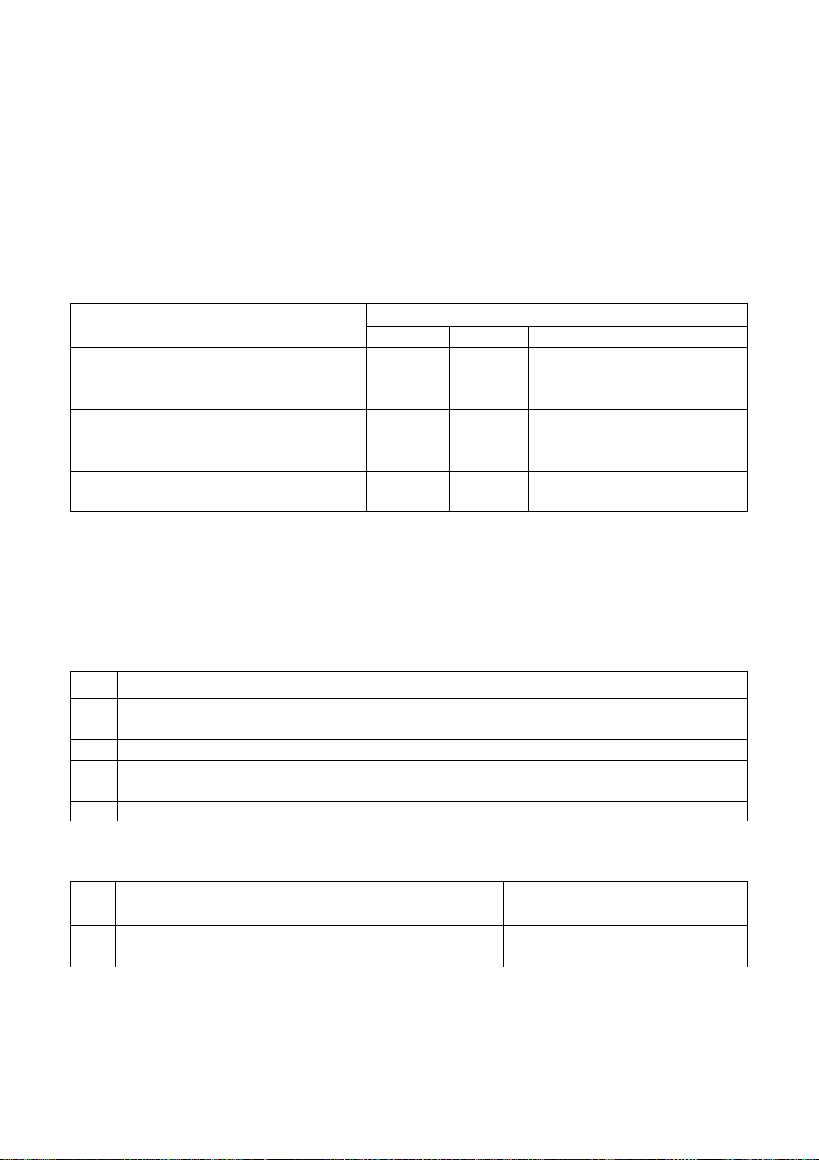
4. AMPLIFIER Section
i. AMPLIFIER Measurement Condition
(a) Power Output : Measure without pre-heating
(b) Source Impedance : Normally 600
(c) S/N : Measure the noise level without low frequency ( 80Hz) vibration
(d) Frequency Response : Measure at -10dBs output (1kHz) by adjusting oscillator output
(e) Difference of L/R ch : The output level difference between L ch and R ch at ± 3dB output
(f) Other : In case of no comment, set volume maximum and 4 load
ii. AMPLIFIER Specifications
Measurement Specifications Measurement Condition/Method/Remarks Measurement
Description Test Input Input Signal Output Vol. Method/Remarks
Point Selector Freq. Level Level
Power Output 15±3W SP out Line 1kHz Adjust Adjust MAX Both channel drive/
front THD 2% 4 load
Distortion Less than 2% SP out Line 1kHz Adjust 12W MAX Both channel drive/
load read best
4
value when indicator
of distortion meter is
changing
Line Input 200±50mV SP out Line 1kHz Adjust Adjust MAX
Sensitivity THD 2%
S/N ≥65dB SP out Line 4.7k
Terminate
Channel more than 30dB SP out Line 1kHz Adjust 5W MAX Measure a ratio of
Separation leak level of L
Frequency ±2dB SP out Line 80Hz Adjust +3dBs MAX Measure the level
Response 12.5kHz difference
Loudness +10dB±5dB H:10KHz Line 1KHz Adjust --- 30Bar Difference from 1KHz
L:100Hz out
Line Out 80±20mV Line out Line 1KHz Adjust Adjust MAX
Level THD 2%
5W MAX
R,
L; Measured
R
channel input terminal
AUX: 4.7k Terminate
- 5 -
Page 8
Measurement Specifications Measurement Condition/Method/Remarks Measurement
Description Test Input Input Signal Output Vol. Method/Remarks
Point Selector Freq. Level Level
Frequency - 5.0 dB ± 3.0dB SP AUX 10Hz Adjust 0dBs MAX Measure the level
Response - 4.0 dB ± 3.0dB OUT
Super Bass + 10dB ± 3.0dB SP AUX 70Hz Adjust 0dBs 30 Measure the level
OUT difference ( S BASS
Loudness Low + 6.0 dB ± 3.0dB SP AUX
Equalizer - 10.0 dB ± 3.0dB OUT Position
High + 5.0 dB ± 3.0dB 10kHz
- 7.0 dB ± 3.0dB
100kHz difference from 1kHz
output
ON)-(S BASS OFF)
at 1kHz Volume
Level 30 Position
100Hz Adjust 0dBs 30 Volume Level 30
III. Level List of Equipments & Instruments Required for Production
NO. Designation Requirement Reference Model Remark
1 Standard signal EXT. MOD. Input LEADER 3216 1 set
Generator Modulation: AM 0-60%
FM 0-99.9KHz
Frequency: 0.1-140MHz
Level: -20-120dBu
Output: 1-50W
2 AC voltmeter Inter Resistance 1M-10MW KENWOOD V7-171 2 set
3 Automatic VP7702C 1 set
Distortion Meter
4 CD Player NF3346A 1 set
Evaluation Filter
5 Multiplex Signal KIKU SUI 3400S 1 set
Generator
6 Oscilloscope Max Frequency of input signal; KENWOOD CO-1305 2 set
5MHz
7 Oscillator Frequency of output signal; KENWOOD AG-203A 2 set
20Hz-20kHz
8 Test Loop Resistance: 50 LEADER LPA-070 1 set
Frequency: 100KHz~30MHz
9 WOW FLUTTER MEGURO 1 set
METER MK-668G
- 6 -
Page 9
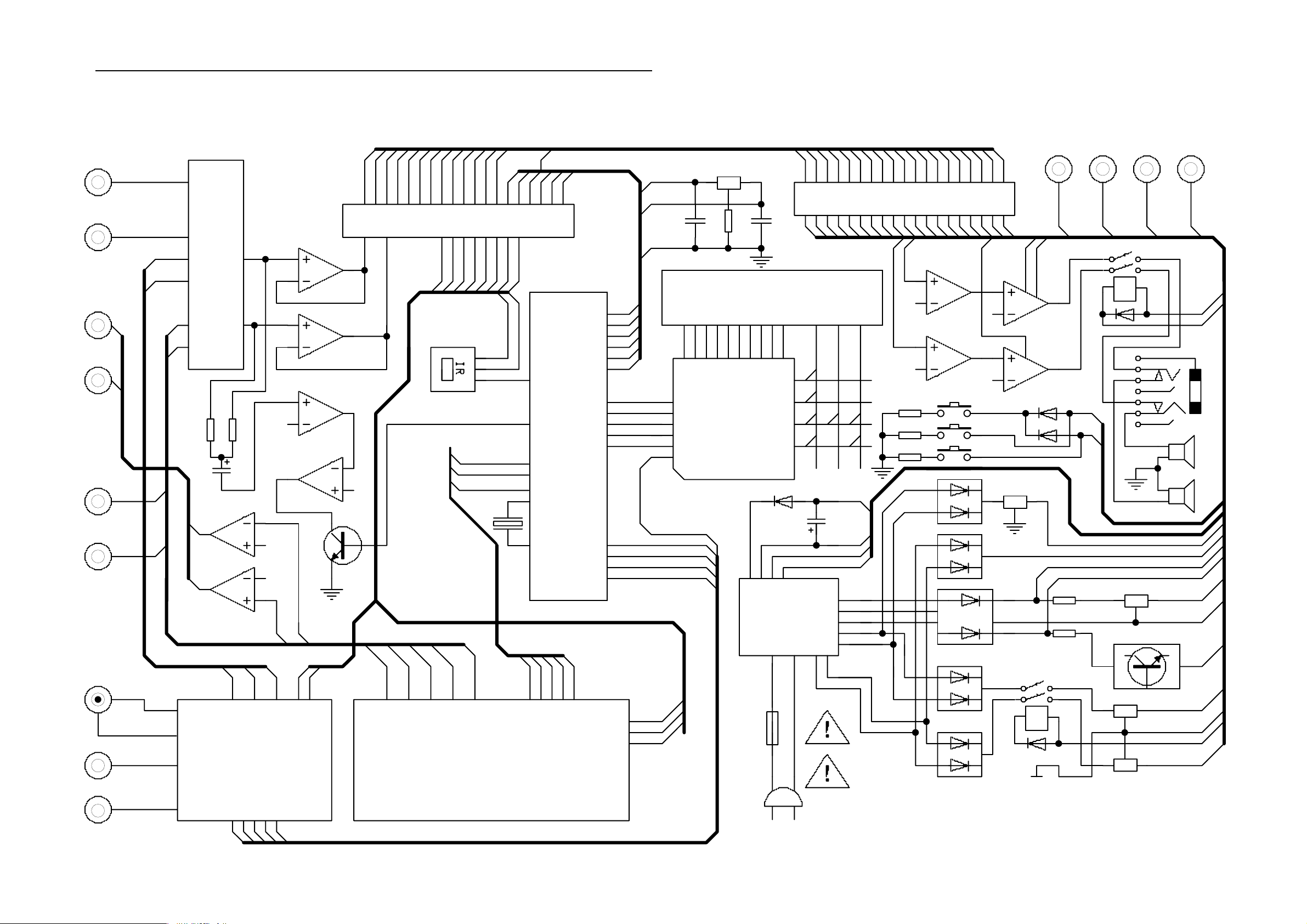
IV. Block diagram
AUX
AUDIO OUT
LINE1 OUT
L
VOL
VOL
R
SYSTEM CONNECTION
MASTER
SYSTEM CONNECTION
LINE2 OUT
L
PT2314
25100-3A08
MUTE
R
MENU
STAN
VFD
JRC4558A
+22V
-22V
LM1876A
MUTE
+5V
DG
REM
REM
LEVEL
DATA
VOL
VOL
SW
78E54
DO
DI
CLK
STB
SW
TU
PT16311
JRC4558B
FUCTION
STAND
LOUD
LM1876B
STAN
MENU
PHONES
LCH
V1
VIDEO OUT
V2
FMAM
LGR
TUNER
T-933-2
AG
+12V
L
G
R
V
G
VCD MEPEG DECODER
DO
STB
CLKDGREM
CE
CLK
DI
DO
+5V
+8V
DG
AC17V
0V
AC3V5
AC3V5
T
AC220V
T4A
AC220V
-21V
0V
F2
F1
AC17V
0V
AC17V
AC10V
AC10V
AC12V
AC12V
7805
+22V
AG
-22V
D5V
DGND
TO CPU
SW
7812
2N5401
7805
TO VCD
7808
TO VCD
RCH
+12V
-12V
D5V
8V
TUNCEDIDOCLK
AC220V IN
- 7 -
Page 10

V. Wiring diagram
- 8 -
Page 11

P701
OT
V
IN
FROM
OUTPUT
AUX IN
FROM
TUNER
0.15K/250V
6A/250V
VI. Schematic Diagram
VIDEO OUT AUDIO OUT
V2 V1 R L
R714
C730
152
DG
R
VCD
R
L
10U
C701
AG
68K
R711
L700
1.8uH
N700B
R708
8K2
R704
6K8
R705
L
R707 6K8
R706 10K
R719 6K8
R718 10K
R716 6K8
R717 10K
R703 6K8
R702 5K6
R701 5K6
R700 6K8
100P
C715
+12V
10K
LCHAGRCH
T01
GTGT
250V/T4A
P301
GT
F300
GT
P700
W300
F3.15A
F3.15A
R409100
C300
GT
L300
UT-20
P300
XP300
GT
8K2
10U
68K
R709
100p
C729
N700A
-12V
C703
10U
C702
10U
10U
C708
10U
C709
10U
C704
C705
5K6
250V
F100
250V
F101
W100 P100
R408100
R41010k
C706
C731
10U
W102
VD402
10U
C707
10U
R722
C408
5V1
100
R713
R712
100K
R724
100K
W502
TO TUNER
100
R715
VCDR
AUXL
TURN
TUNL
VCDL
104
5K6
R723
C108~C111
103X4
BF40C6A
VD113
P102
VD400
22V
VD401
104
2U2
C719
C723
IN4007
220U/35V
C409
TUN
CE
DI
DO
CLK
10U
C710
104
C724
F1
104
F1
C700
C711
LOUL
LIN
10U
C732
104
PT2314
N702
BINL
LOUT
C721
104
G1
G2
LED5
LED4
LED3
LED2
LED1
AUXR
LOUR
BINR
BOUL
G3
GR5
GR4
GR3
GR2
GR1
VDD
GND
OSC
C712
ROUT
BOUR
C722
104
G5
G4
2U2
RIN
L
R721
47K
GTGT
IN4007
VD100
C126
103
IN4007
VD101
C127
103
IN4007
VD103
C128
103
IN4007
VD102
C129
103
IN4007
VD104
C130
103
IN4007
VD105
C131
103
IN4007
VD107
C132
103
IN4007
VD106
C133
103
G7
G6
GR6
+5V
SW1
272
TRR
TRL
AGND
R
DO
DG
C725
10U
2200U/25V
C106
2200U/25V
P3
P2
P1
GR8
GR7
SG20
PT16311
N600
SW2
SW3
SW4DODINCCLK
C713
VCC
REF
DI
10U
C726
C107
P4
SG19
C714
272
22U
C718
P7
P6
P5
+5V
-21V
SG18
100U
47K
R725
47K
104
C121
RL100
HRS2H-S
C120
1000U/25V
VD108
IN4007
IN4007
VD109
P10
P9
P8
SG17
SG16
SG15
STBK1K2K3K4
C717
104
W505
R720
R726
47K
C137
104
C138
220U/25V
1000U/16V
VD110
IN4001
P15
P14
P13
P12
P11
KS12
KS11
KS10
SG13
SG14
KS9
KS8
KS7
KS6
KS5
KS4
KS3
KS2
KS1
VDD
P505 P501
C716
DG
DI
DO
180
R710
8
5
6
JK2
N701B
JRC4558:A
4
3
2
N701A
JRC4558:A
220U/25V
C115
100/3W
R107
470/3W
R106
L7805CV
N100
L7808CV
N101
C43
100U/25V
470U
P16
C123
1000U
C52
P17
K1
LEVEL
7
1
3K3
1000U
10K
R111
R112
100
L7805CV
N104
F2
+12
+12V
C112
R108
C122
F2
IN4148
VD600
IN4148
VD601
IN4148
VD603
IN4148
VD602
R601
10K
RCH
-12
C728 10U
10U
V102
2N5401
VFD600
25100-3A08
DGND
AN
K601
+5V
AN
K600
AN
K603
AN
K606 K602
DI
DO
W501
LCH
GND
22K
R564
C727
L7812CV
N103
12V
VD112
C124
104
C125
104
C9014
V100
R602
10K
AN
K4
STB
CLK
R509
22K
C116
100U
C53
100U/16V
R603
10K
AN
K605K604
AN
K3
TUN
SW
100
R563
C9014
C114
100U
C113
100U
100
R110
IN4148
VD111
C9014
V101
CPU POWER
10K
KS5
KS4
KS2
KS1
K2
V503
CON26P
R604
22K
V502
C9014
DGND
+5V
+12V
-12V
L R
- 9 -
R561
+5V
N601
24C02
DI
DO
DGND
+5V
AG
AG
-12V
+12V
RP200
EC-16B
+8V STAN
-21V
0V
R208 100
4K7X8
R513
X500
12MHZ
30P
C505
10K
R500
MUTE
VOL2
VOL1
DGDGF2F1-V
DG
DG
W104 P104
F2
F1
W101
C100
4U7
22K
+22V
-22V
R512
4K7X8
SW
P101
DG
C104
330P
IN4148
+5V
DG
R100
30P
C504
VD500
+8V
+5V
MUTE
LM1876TFA
N102A
RIN
C101
4U7
R3
8
C401
22K
7
1K
R102
10
11
12
13
14
15
16
17
18
19
10U
AGND
2
4
89C58
1
2
3
4
5
6
7
8
9
LIN
R401
VCD
N500
P10
P11
P12
P13
P14
P15
P16
P17
REST
CE
MENU
REMIN
STB
VOL1
VOL2
MUTE
STAN
X1
X2
C503
10U
+5V
100K
DG
+8V
R400
39
P00
38
P01
37
P02
36
P03
35
P04
34
P05
33
P06
32
P07
21
P20
22
P21
23
P22
24
P23
25
P24
26
P25
27
P26
28
P27
40
VCC
31
VCC
30
ALE/P
29
PSEN
20
GND
LEVEL
W500
TO VCD MPEG
DG
SYSTEM CONNECTION
R403
4K7
JRC4558:A
2
3
1K
R404
47U
C402
5
6
REMO
100K
N400A
4
JRC4558:B
8
N400B
1K
R407
47U
C404
MUTE CONTROL
6
3 1
9
5
24K
R104
47u
C102
47uC103
1K
R103
10U
C720
4K7
R402
10U
C400
C406
1
100P
R4053K3
C407
100P
7
3K3
R406
LM1876TFB
N102B
15
13
12
C105
330P
14
104
24K
R105
R560
C506
LCH
RCH
C405
10U
11
10
4K7
R503
33K
1
CON26P2
FC-26P
N502A
JRC4558
C501
103
JRC4558
100P
C502
-12V
AG
10U
C403
4K7
R502
4K7
R501
N502B
+12V
AG
LOUT
LGND
RGND
ROUT
DGND
+12V
3
2
10K
470K
R508
MUTE
STAN+8V
+5V
VOL2
DG
DG
W104 P104
68K
R306
39K
R305
VOL1
DG
220K
15K
DGND
REM
CLK
STB
DO
R565
DG
R307
R304
F2
A1015
220U
C303
F1
TO VCD MPEG
K202 R222
R220
VD206
IN4148
SW
+5V
-21V
V300
V302
V301
18
K200 R209
150
R210
VD207
L301
1UH
C1815
C1815
33K
L302
100
K201 R204
R211
100
R205
IN4148
STAND
+5V
VOL2
VOL1
REM
MENU
DGND
4.7
R300
1UH
P200
LIN
P503W503
R301
4.7
LOUT
100
R206
100
V201
C9014
AGND
RIN
33K
ROUT
104
V200
C9014
C9014
V202
R303
4.7
IN4148
VD300
W200
C205
W201P201
4.7
R302
C305
102
C301
104
C302
RL300
HRS2H-S
10K
C304
104
R203
680
560
R202
R207
1K
104
C206
47P
102
R213
C202
IR200
100
R221
RCHLCH SPEKEAR OUT
R212
10K
180
R214
180
R215
R216
180
180
R217
180
R218
1838
C201
223
C200
223
560
R201
+5v
GND
REM
VD200
VD204
VD202
VD205
VD203
VD201
PHONES
R200
680
LED
LED
LED
LED
LED
LED
C204
C203
104
47U
P202
Page 12

VII. Component Diagrams
i. AMP PCB Component Diagram
- 10 -
Page 13

ii. AMP CONTROL PCB Component Diagram
- 11 -
Page 14

iii. AMP OUTPUT PCB Component Diagram
- 12 -
Page 15

iv. CONNECTIVE PCB Component Diagram
- 13 -
Page 16

v. CPU CONTROL PCB Component Diagram
- 14 -
Page 17

vi. VCD CONTROL PCB Component Diagram
- 15 -
Page 18

vii. AUDIO/VIDEO OUTPUT PCB Component Diagram
- 16 -
Page 19

viii. REMOTE HANDSET PCB Component Diagram
- 17 -
Page 20

VIII. Exploded Diagram View and Parts List
A. VCD exploded
- 18 -
Page 21

Parts list for VCD exploded view diagram
Location Part No. Discription QT Y
1 405-AA0902-05 PANEL FRONT 1
2 263-AA0901-06L FRONT LENS 1
3 370-AA0801-01 FOOT CSH 2
4 227-AA0921-06S MTB CV CD 1
5 260-AA0901-01L LENS REAR 1
6 CSH 2
7 E7801-013006 FRONT CONTROL PCB ASSY 1
8 224-AA0902-01B HOLD PCB 1
9 403-AA0903-01 CHASSIS BOTTOM 1
10 370-AA0802-01 FOOT CSH REAR 2
11 322-AA0801-01 SPOG SPR 6
12 E7801-013007 OUTPUT PCB ASSY 1
13 402-AA0903-05 REAR COVER 1
14 E7801-013009 TUNER PCB ASSY 1
15 E7801-013008 MPEG PCB ASSY 1
16 530-V58001-01 FIBER PAPER WASHER 4
17 401-AA0902-01 TOP CABINET 1
18 429-AA0901-01 BRACKET FOR PCB 2
19 E7801-013005 CPU PCB ASSY 1
20 239-AA0901-07S CD DOOR 1
21 E7706-003001 MECHANISM VCD 1
A 610-200108-10 S-TAP . SCREW RND 2x8 1
B 610-300108-90 S-TAP . SCREW RND 3x8 9
C 610-300106-90 S-TAP . SCREW 3x6 25
D 611-300208-10 S-TAP. SCREW FLT 3x8 2
- 19 -
Page 22

B. AMP exploded
- 20 -
Page 23

Parts list for AMP exploded view diagram
Location Part No. Discription QT Y
1 739-AA0802-04 ASY+VOL 1
2 405-AA0803-04 PNL FR B 1
3 405-AA0802-06 PNL FR A 1
4 289-AA0803-03L RNG+VOL 1
5 227-AA081 1-05S BRACKET FOR COVER 1
6 269-AA0802-01K L+AA 1 1
7 269-AA0803-01K L+AA 2 1
8 E7801-013002 AMP CONTROL PCB 1
9 E7801-013001 AMP PCB 1
10 E7801-013003 AMP OUTPUT PCB 1
11 429-AA0801-1 BRACKET FOR PCB 2
12 HTSK 1
13 367-V58801-01 BSHG RELIEF 1
14 236-AA0811-22S CABINET BACK 1
15 E3404-136001 AC LINE CORD 1
16 384-K58001-02H BACK PLATE 1
17 E7801-013004 CONNECTIVE PCB 1
18 403-AA0803-01 CABINET BOTTOM 1
19 370-AA0802-01 FOOT CSH REAR 2
20 E5102-151001 TRANSFORMER 1
21 269-AA0821-01K LENS+RCN FLTR 1
22 370-AA0801-01 FOOT CSH 2
23 401-AA0803-01 CABINET TOP 1
24 389-AA0802-01H PLT SHD PCB 1
A 61 1-300208-10 S-TAP. SCREW FLT 3x8 2
B 610-300108-90 S-TAP . SCREW RND 3x8 12
C 610-300106-90 S-TAP . SCREW 3x6 19
D 612-400108-10 S-TAP . SCREW WHR 4x8 8
E 660-907520-1 1 NUT 9x11x2 1
- 21 -
Page 24

C. Remote handset
11
Location Part No. Discription QT Y
1 384-010101-11H REMOTE OVERLAY 1
2 201-010111-22S REMOTE CAB TOP 1
3 373-010101-03Y REMOTE CONTATIVE RUBBER 1
4 090-385610-03 P.C.B. REMOTE BOARD 1
5 473-010101-01 BA TT CONTACT SPRING SHEET-VE 1
6 472-010101-01 BA TT CONTACT PLATE+VE 1
7 203-010131-03S REMOTE CABINET BOTTOM 1
8 61 1-260206-10 SELF-TAPPING SCREW K/T 2.6x6mm 1
9 474-010101-01 BA TT CONTACT SPRING WIRE 1
10 210-010101-03S REMOTE BATTERY COVER +/- VE 1
11 790-010110-11 REMOTE CONTROL HANDSET (43 KEYS) 1
- 22 -
Page 25

D. Elec. Parts list
i. RESISTOR
Location Description QTY
R22 RESISTOR CARBON 18 1/16W ±5% 1
R110 RESISTOR CARBON 100 1/16W ±5% 5
R1 1 2
R509
R713
R715
R710 RESISTOR CARBON 180 1/16W ±5% 1
R102 RESISTOR CARBON 1K 1/16W ±5% 2
R103
R108 RESISTOR CARBON 3K3 1/16W ±5% 1
R501 RESISTOR CARBON 4K7 1/16W ±5% 3
R502
R503
R701 RESISTOR CARBON 5K6 1/16W ±5% 4
R702
R722
R723
R700 RESISTOR CARBON 6K8 1/16W ±5% 6
R703
R704
R707
R716
R719
R111 RESISTOR CARBON 10K 1/16W ±5% 13
R500
R505
R601
R602
R603
R604
R705
R706
R708
R714
R717
R718
R304 RESISTOR CARBON 15K 1/16W ±5% 1
R100 RESISTOR CARBON 22K 1/16W ±5% 8
R101
R506
R508
R510
R511
R562
R564
R104 RESISTOR CARBON 24K 1/16W ±5% 2
R105
R507 RESISTOR CARBON 33K 1/16W ±5% 1
R305 RESISTOR CARBON 39K 1/16W ±5% 1
R720 RESISTOR CARBON 47K 1/16W ±5% 4
R721
R725
R726
R600 RESISTOR CARBON 56K 1/16W ±5% 1
R306 RESISTOR CARBON 68K 1/16W ±5% 3
R709
R711
R712 RESISTOR CARBON 100K 1/16W ±5% 2
R724
R307 RESISTOR CARBON 220K 1/16W ±5% 1
R504 RESISTOR CARBON 470K 1/16W ±5% 1
R204 RESISTOR CARBON 100 1/4W ±5% 8
R205
R209
R210
R219
R221
R408
R409
R220 RESISTOR CARBON 150 1/4W ±5% 1
R214 RESISTOR CARBON 180 1/4W ±5% 5
R215
R216
R217
R218
R208 RESISTOR CARBON 220 1/4W ±5% 1
R201 RESISTOR CARBON 560 1/4W ±5% 2
R203
R200 RESISTOR CARBON 680 1/4W ±5% 2
R202
R207 RESISTOR CARBON 1K 1/4W ±5% 3
R405
R406
R404 RESISTOR CARBON 3K3 1/4W ±5% 2
R407
R400 RESISTOR CARBON 4K7 1/4W ±5% 2
R402
R212 RESISTOR CARBON 10K 1/4W ±5% 3
R213
R410
R206 RESISTOR CARBON 33K 1/4W ±5% 2
R211
R401 RESISTOR CARBON 100K 1/4W ±5% 2
R403
R300 RESISTOR CARBON 4.7 1W ±5% 4
R301
R302
R303
R107 RESISTOR CARBON 100 3W ±5% 1
R106 RESISTOR CARBON 470 3W ±5% 1
R512 RESISTOR 4K7 ±5% 9PIN 2
R513
ii. CAPACITOR
Location Description QTY
C504 CAPACITOR CERAMIC 30PF/50V ±20% 2
C505
C202 CAPACITOR CERAMIC 47PF/50V ±20% 1
C406 CAPACITOR CERAMIC 100PF/50V ±20% 5
C407
C502
C715
C729
C104 CAPACITOR CERAMIC 330PF/50V ±20% 2
C105
C304 CAPACITOR CERAMIC 102PF/50V ±20% 3
C305
C730
C108 CAPACITOR CERAMIC 103PF/50V ±20% 13
C109
C110
C111
C126
C127
C128
C129
C130
C131
C132
C133
C501
C200 CAPACITOR CERAMIC 223PF/50V ±20% 2
C201
C713 CAPACITOR CERAMIC 272/50V ±20% 2
C714
C124 CAPACITOR CERAMIC 104/50V ±20% 22
C125
C134
C135
C137
C138
C203
C205
- 23 -
Page 26

C206
C301
C302
C409
C506
C507
C508
C710
C711
C716
C721
C722
C723
C724
C100 CAPACITOR ELEC 4.7uF/16V ±20% 2
C101
C400 CAPACITOR ELEC 10uF/16V ±20% 22
C401
C402
C405
C503
C700
C701
C702
C703
C704
C705
C706
C707
C708
C709
C720
C725
C726
C727
C728
C731
C732
C718 CAPACITOR ELEC 22uF/16V ±20% 1
C113 CAPACITOR ELEC 100uF/16V ±20% 9
C1 1 4
C1 1 8
C204
C403
C404
C500
C509
C717
C116 CAPACITOR ELEC 220uF/16V ±20% 1
C119 CAPACITOR ELEC 470uF/16V ±20% 1
C121 CAPACITOR ELEC 1000uF/16V ±20% 3
C122
C123
C136 CAPACITOR ELEC 10uF/25V ±20% 1
C102 CAPACITOR ELEC 47uF/25V ±20% 2
C103
C117 CAPACITOR ELEC 100uF/25V ±20% 1
C112 CAPACITOR ELEC 220uF/25V ±20% 3
C1 1 5
C303
C120 CAPACITOR ELEC 1000uF/25V ±20% 1
C408 CAPACITOR ELEC 220uF/35V ±20% 1
C106 CAPACITOR ELEC 2200uF/35V ±20% 2
C107
C712 CAPACITOR ELEC 2.2uF/50V ±20% 2
C719
C300 CAP H-VOLTAGE MKP-0.15K/275V ±20% 1
iii. DIODE.TRANSISTOR
Location Description QTY
VD111 DIODE IN4148 9
VD206
VD207
VD403
VD500
VD600
VD601
VD602
VD603
VD11 0 DIODE IN4001 2
VD300
VD100 DIODE IN4007 13
VD101
VD102
VD103
VD104
VD105
VD106
VD107
VD108
VD109
VD114
VD115
VD400
VD200 DIODE LED F3 YELLOW 3
VD202
VD204
VD201 DIODE LED F3 GREEN 3
VD203
VD205
VD402 DIODE ZENER 5V1 0.5W 1
VD112 DIODE ZENER 12V 1W 1
VD401 DIODE ZENER 22V 1W 1
VD11 3 DIODE BRIDGE BF40C6A 1
V100 TRANSISTOR C9014 β≥250 7
V101
V200
V201
V202
V502
V503
V301 TRANSISTOR C1815 β≥250 2
V302
V300 TRANSISTOR A1015 β≥250 1
V102 TRANSISTOR 2N5401 β≥250 1
N100 TRANSISTOR ZENER L7805CV 2
N104
N101 TRANSISTOR ZENER L7808CV 1
N103 TRANSISTOR ZENER L7812CV 1
iv. IC
Location Description QTY
N400 IC, JRC4558 4
N502
N700
N701
N600 IC, PT16311 1
N702 IC, PT2314 1
N102 IC, LM1876TF 1
N601 IC, HT24C02 1
N500 IC, CPU(89C58) 1
- 24 -
Page 27

v. OTHERS
Location Description QTY
RP200 ENCODER VOLUME 1PCS
L700 INDUCTANCE 1.8UH 1PCS
L300 COIL INDUCTANCE 3UH 1PCS
L301 COIL INDUCTANCE 1UH 2PCS
L302
X500 CRYSTAL 12MHZ 1PCS
IR200 REMOTE SENSOR 1838 1PCS
VFD600 VFD 25100-3A08 1PCS
XS700 RCA SOCKET AV6-8.4-7 1PCS
XS300 JACK SPK WP4-15 1PCS
P202 JACK HEADPHONE 7PIN 1PCS
RL100 RELAY YL-202 (DC12V) 1PCS
RL300
F100 FUSE F3.15A/250V 1PCS
F101
F300 FUSE T4A/250V 1PCS
F100 FUSE HOLD 2PAIR
F101
F300 FUSE HOLD 1PCS
P300 AC LINE CORD 1.8M 1PCS
K200 SWITCH TACT 6x6x9.5 10PCS
K201
K202
K600
K601
K602
K603
K604
K605
K606
AV LINE (RED, WHITE, YELLOW) L=1.2M 1PCS
FM ANTENNA 1.8M 1PCS
AM ANTENNA 1PCS
CONNECTOR WIRE (See attachment 1) 1SET
- 25 -
Page 28

(Attachment 1)
 Loading...