

Akai LM-H17CLSA Service Manual

Service Manual
AKAI
17” Wide Screen
LCD Multi-Media Display
L
L
M--
M
H
H
1
1
7
7
C
C
L
L
S
S
A
A

Table of Contents
1. Safety and Precautions …………………………………………………………1
2. Specifications.........................................................………………………………3
2.1 Specification.........................................……………………….…..3
2.2 PC I/P Preset Timing Table.....................................................…..4
3. Connection & Applications……………………..............................................…..5
4. Controls Location ..........................................................................……………….7
5. Remote Control..............................................................................………………..8
6. Disassembly Instructions.......................…………………………….……..……..11
7. Block Diagram....................................................………………………………….15
8. Troubleshooting……………...............................................………………………16
8.1 Symptom Codes ( for call center use). .............…………….…16
8.2 Flow Chart ( for service center use) ……….………....……….19
9. Electronic Circuit Description.....................................………………………..…24
10. Circuit Diagram...................................................…………………………..…….29
10.1 Main & Tuner Board......................…………………….……..29
10.2 Key & LED Board ......................……………………….…….40
11. PCB Layout...................................................…………………………………..…41
11.1 Main & Tuner PCB.......……………………………..………..41
11.2 Key & LED PCB…………………………………….……..….43
12. Electrical Parts List.....................................………………………………….…..44
13. Mechanical Disassembly....….............................................……………….……..51
14. Mechanical Parts List................................................……………………………52

1. Safety and Precautions
CAUTION
* The service of this LCD-TV must be carried out by qualified persons only.
* Do not change any module unless the set is switched off.
CLEANING:Always disconnect unit from mains supply before attempting to clean it.
Use soft cloth moistened with soapy water, wipe gently. Do not use
solvents of abrasive materials.
SOME DO’S AND DON’T’S ON THE SAFE USE OF EQUIPMENT
This equipment has been designed and manufactured to meet European
safety standards but like any electrical equipment, care must be taken if
you are to obtain the best results and safety is to be assured.
Do read the operating instructions before you attempt to use the equipment.
Do ensure that all electrical connections (Including the mains plug, extension leads
and interconnections between pieces of equipment) are properly made in accordance
with the manufacturer’s instructions. Switch off and withdraw the mains plug when
making or changing connections.
Do use only the power supply (AC adapter ) and power cord provided.
Do consult your dealer if you are ever in doubt of the installation, operating, or safety
of your equipment.
Don’t exert pressure on the LCD TV . This could break the panel .
Don’t continue to operate the equipment if you are in any doubt about it working
normally, or if it is damaged in any way. Switch off, withdraw the mains plug and
consult your dealer.
Don’t remove any fixed covers as this may expose dangerous voltages.
Don’t leave equipment switched on when it is unattended unless it is specifically
stated that it is designed for unattended operation or has a standby mode. Switch off
using the switch on the equipment and make sure that everyone knows how to do this.
Special arrangements may need to be made for infirm or handicapped people.
-1-

Don’t listen to headphones at high volume, as such use can permanently damage
your hearing.
Don’t obstruct the ventilation of the equipment, for example, with curtains or soft
furnishings. Overheating will cause damage and shorten the life of the equipment.
Don’t allow electrical equipment to be exposed to rain or moisture.
Above all
─ Never let anyone push anything into holes, slots or any other opening as this could
result in a fatal electric shock.
─ Never guess or take chances with electrical equipment of any kind.
─ It is better to be safe than sorry!
WARNING:TO REDUCE THE RISK OF FIRE OR ELECTRIC SHOCK, DO NOT
EXPOSE THIS APPLIANCE TO RAIN OR MOISTURE. DANGEROUS
HIGH VOLTAGES ARE PRESENT INSIDE THE ENCLOSURE. DO
NOT OPEN THE CABINET. REFER SERVICING TO QUALIFIED
PERSONNEL ONLY.
-2-

2.1 Specification :
ITEMS SPECIFICATION
Screen size 17” Wide TFT-LCD Panel (Fujitsu)
Aspect Ratio
Resolution 1280 x 768 (Wide-XGA)
Display
TV Function
Video I/O
PC I/P
Audio O/P
Other Functions
Power
Panel Tilt
Weight (net)
Accessories
Contrast Ratio 400 : 1 (Typical)
Brightness 400 cd/m² (Typical)
Viewing Angle 160° (Hor.) / 160° (Vert.)
Response Time : Ton / Toff 15ms / 10ms
OSD Language English, French, German, Spanish, Italian
TV Standard (CCIR) B/G, D/K, I and L/L’ (Multi-Europe)
Color System PAL / SECAM
Sound System NICAM / A2 (IGR)
Teletext 10 Pages (FLOF / TOP )
Color System PAL / SECAM / NTSC
AV1 (In / Out) 21-pin SCART (RGB / Video) x 1
AV2 (In)
AV3 (Out) Video (Composite) TV only x 1
Signal I/P Analog : D-Sub 15 pin (detachable cable)
PnP compatibility DDC / 2B
I/P Frequency
Recommended Analog: 1024x768 (60Hz)
DTV ready (via D-sub 15pin) DTV System : 625p
Audio O/P: L/R
PIP under PC mode Yes
A.P.S. , Child-Lock Yes
VESA Panel Wall Mounting Holes 100mm x 100mm
Power Supply
Power Consumption < 60W
Forwards/ Backwards /Rotation -5°/ +15° / ±180°
6.5 Kg (Without Accessories)
Remote Control, Batteries x 2 , AC adapter, AC cord, 15 Pin D-Sub Signal Cable ,
Cable Clamps , Operation Manual .
2. Specifications
16:9
Video (Composite) x 1
S-Video x 1
Component (YPbPr, YCbCr) x 1
( DTV system : 625p)
Analog: F
F
Speaker (Built-in) : 3.5W+3.5W (rms)
Headphone Mini-jack for stereo (3.5 mm)
Line Out (RCA L/R)
DC 12V / 5A (external AC adapter)
AC 100V~240V, 50/60Hz
-3-
H: 31kHz to 60kHz
v: 56Hz to 75Hz
Audio
L/R x 1

2.2 PC I/P Preset Timing Table :
Analog Input
Mode No.
1
2
3
4
5
6
7
8
Mode Name
Resolution
VGA 70Hz
640x350
VGA 60Hz
640x480
VGA 72Hz
640x480
VGA 75Hz
640x480
SVGA 56Hz
800x600
SVGA 60Hz
800x600
SVGA 72Hz
800x600
SVGA 75Hz
800x600
H.Freq. (kHz)
V.Freq. (Hz)
31.469
70.087
31.469
59.941
37.861
72.81
37.5
75.0
35.16
56.25
37.876
60.317
48.077
72.118
46.875
75.0
H. Polarity
V. Polarity
+
-
-
-
-
-
-
-
+
+
+
+
+
+
+
+
Pixel
CLK
(MHZ)
25.175
25.175
31.5
31.5
36.0
40.0
50.0
49.5
9
XGA 60Hz
1024x768
XGA 70Hz
10
1024x768
XGA 75Hz
11
1024x768
MAC VGA
12
640x480
MAC VGA
13
832x624
US TEXT
14
720x400
WXGA 60Hz
15
1280x768
48.363
60.004
56.476
70.069
60.023
75.029
35.0
66.667
49.725
74.550
31.469
70.087
47.733
60.042
-4-
-
65.0
-
-
75.0
-
+
78.75
+
-
30.24
-
-
57.283
-
-
28.322
+
80
-

3. Connection & Applications
-5-
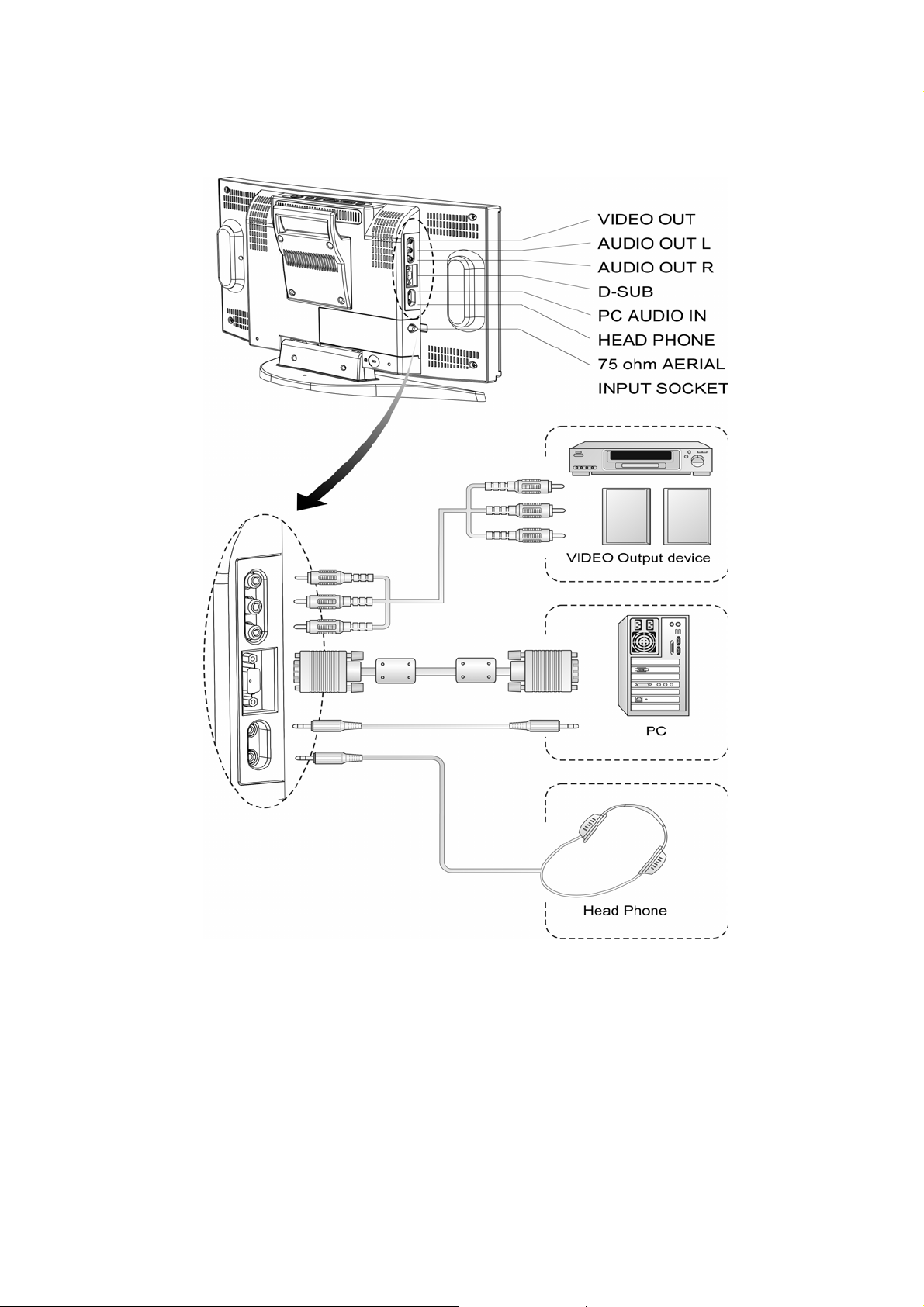
(for TV only)
NOTE:
z Audio out : The level of audio output cannot be changed using the volume , treble , and bass
controls on your TV . These connectors should be used with an external audio amplifier
that can be used to control the volume.
z VCR Recording: The main display must set to TV mode in order to use the audio and video output to
record a program using a VCR .
z PIP sound : When using the PIP feature in PC mode , to hear the Sub display sound you must set
the sound source to “Sub” .
-6-

4. Controls Location
r
p
The buttons control your TV’s basic features, including the on-screen menu. To use the more
advanced features, you must use the remote control.
POWER: turn on or turn off the LCD TV.
SOURCE: set up the input source (PC, TV, SCART Video/ SCART RGB ,
Video, S-Video, Component)
MENU: display the main menu.
CHANNEL (down/up): change channels.
VOLUME (-/+): turn up or turn down the volume.
ASPECT RATIO: set up the ratio of display (Normal, Panscan, Zoom or Full.)
ASPECT RATIO VOLUME(-/+ ) CHANNEL(down/up) MENU SOURCE POWER
Speake
Remote sensor window
Aim the remote control
towards this region on the
TV.
S
Power indicator
A green indicator lights when the power is on
and a red indicator lights when in the standby
mode (the indicator will not light when the main
power is off).
-7-
eaker
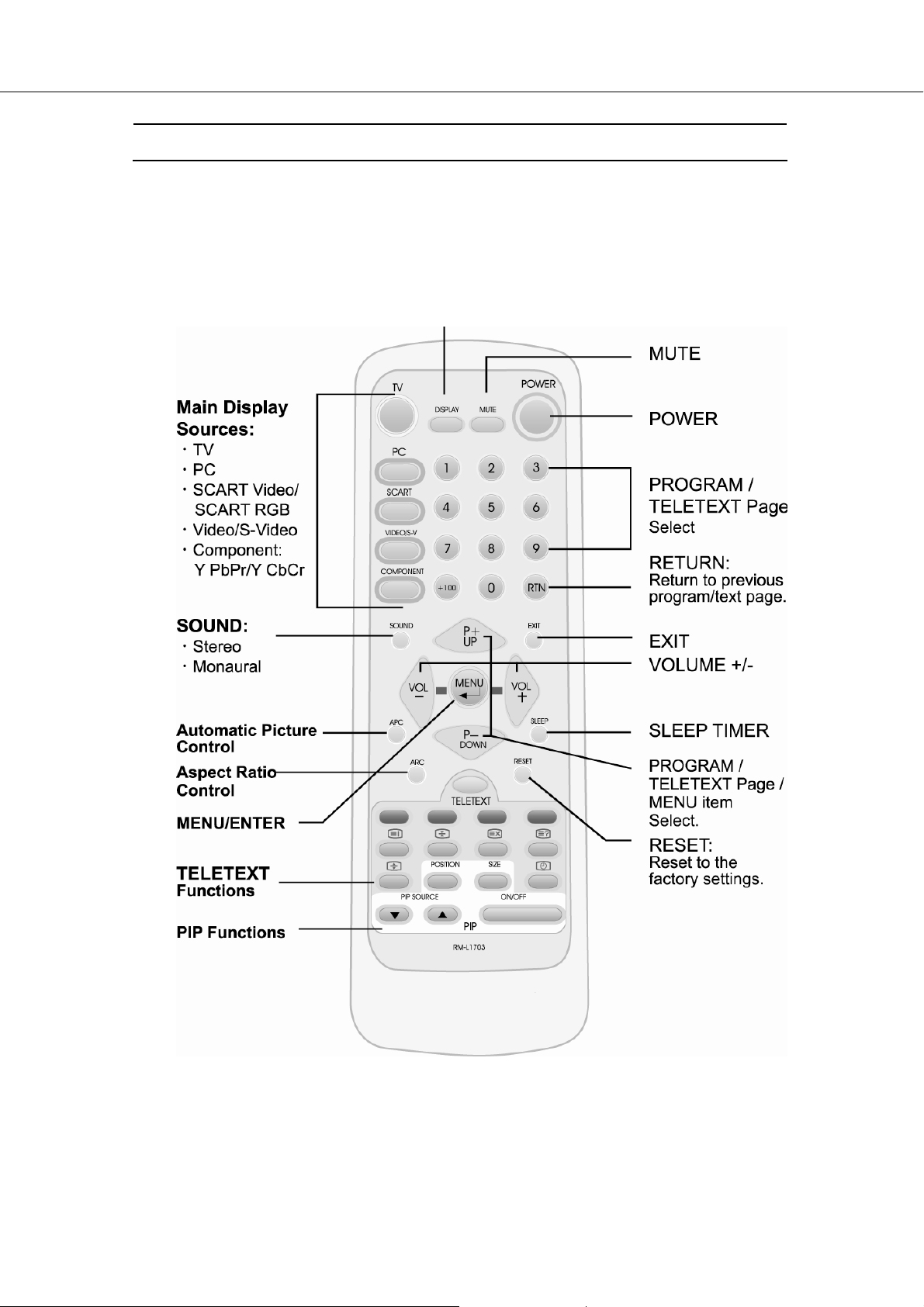
5. Remote Control
The remote control pad works almost same as ordinary TV remote control that includes the
basic function needed while viewing a live video.
DISPLAY : Display the current source or program digits .
-8-

Summary of Control Buttons
Selecting the Signal Source
TV
PC
SCART
VIDEO/S-V
COMPONENT
DISPLAY
Menu Setting
MENU/ENTER
UP/DOWN
VOL- / VOL+
EXIT
Changing Channels
P- / P+
0 ~ 9
DISPLAY
RTN
Sound Control
VOL+ / VOL-
MUTE
SOUND
Teletext Control
TELETEXT
INDEX
HOLD
UPDATE
Switch to the TV mode.
Switch to the PC mode.
Switch to the Video mode or RGB mode from SCART.
Switch to the Video mode from RCA socket or S-Video mode.
Switch to the Component mode (YPbPr or YCbCr).
Display the current source.
Display the main on-screen menu or enter the next menu.
Press to select the item you want to adjust in the OSD menu.
Press to decrease or increase the value in the OSD control bar.
Exit from the menu.
Press P- or P+ to change Programs in TV mode or Teletext page in
TELETEXT mode.
To select programs directly in TV mode.
Display the current program digits.
Press to return to the previous program.
Press to turn up or turn down the volume.
Press to switch the sound on or off.
Press to choose Stereo, Bilingual and Monaural broadcasts.
Press to show the Teletext Service. Press again to return to TV Viewing.
Press “ INDEX“ button to show the list of teletext contents.
Press “ HOLD“ button to stop the automatic page change.
Press “ UPDATE“ button to switch to TV while waiting for the next text page.
-9-
RTN
REVEAL
EXPAND
SUB-PAGE/TIME
Press “REVEAL“ button to display concealed information, such as
solutions of riddles or a quiz.
Press “EXPAND“ button to enlarge the top half or bottom half of the
Teletext page.
Press “SUB-PAGE/TIME“ button to access to the sub-page you
required.
Press to return to the previous viewed Teletext page.
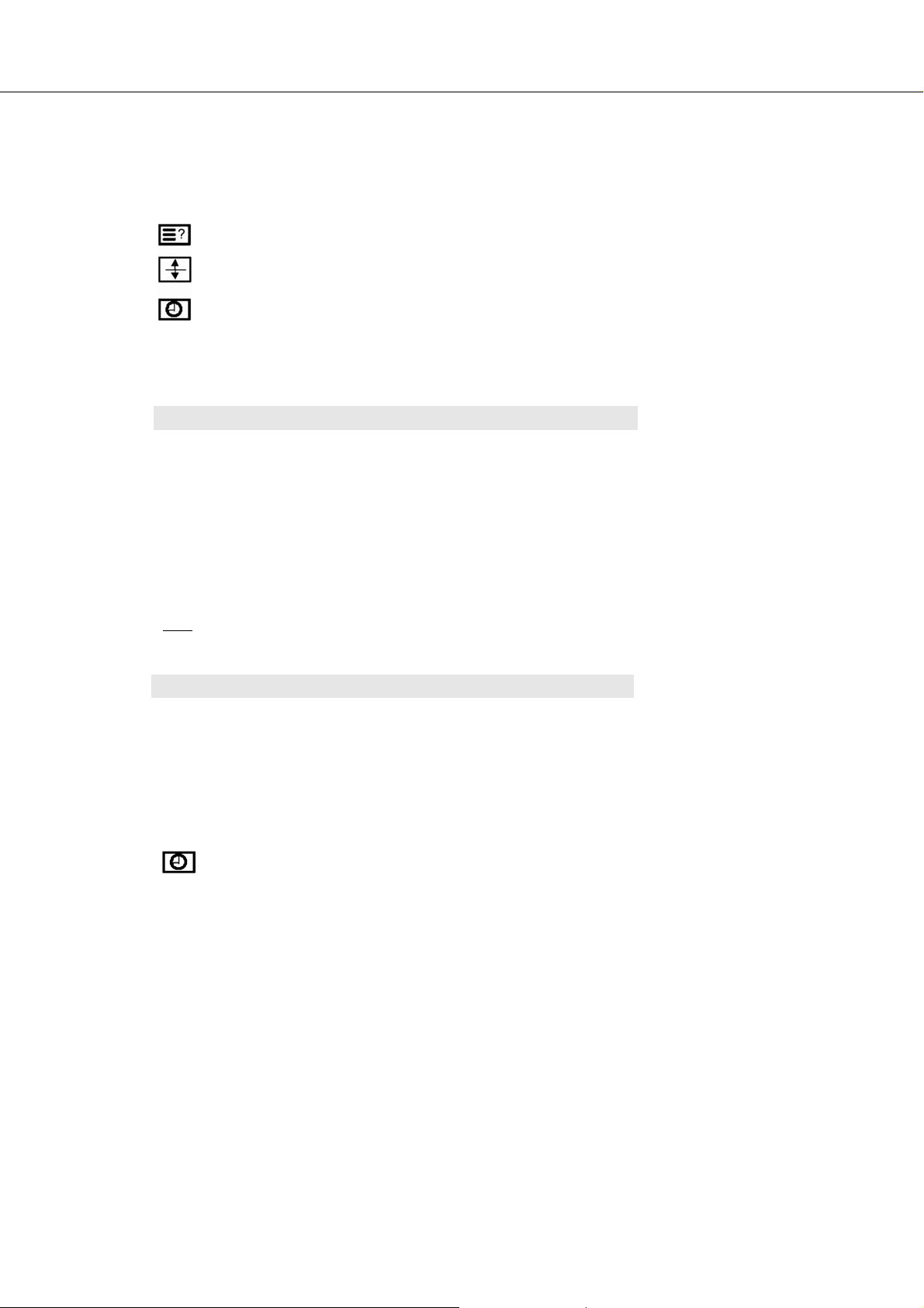
PIP Control
ON / OFF
PIP Source
SIZE
POSITION
NOTE : When you set Main-display at 1280x768/1024x768 resolution of PC mode and Sub-display
YPbPr, the screen will appear “Not Available“. You should reduce the PC resolution to 800 X
Other Function
600 or 640 X 480. The PIP function will then work.
RESET
ARC
APC
SLEEP
SUB-PAGE/TIME
Press to watch one of the video sources on Sub-display, whilst in
PC mode. Press again to turn off the Sub-display.
Press to select the PIP window input source as :
Press ▲ button : TV→ SCART Video→SCART RGB→ Video→
Press ▼ button : Component→ S-Video → Video→ SCART RGB
To make the PIP window double, large or small.
Press to move the PIP window to: Top Left → Top Right→
Bottom Right → Bottom Left → Repeat.
S-Video→ Component
→SCART Video→ TV
Reset to the original factory settings, such as theBrightness/Contrast/
Color Temp.
Set the picture window to Normal(4:3) → Panscan→ Zoom→ Full
(16:9)
To select Clear,Dark, or Nomal mode for picture control.
Press to select a preset time interval for automatic power off .
Press “Sub-Page/Time“ to display the digital clock in TV mode.
.
-10-
6. Disassembly Instructions
1) Face down the LCD-TV :
Face down the LCD-TV on a smooth plane with a soft material to protect
the panel faceplate .
2) Tuner Board Removal :
Note: If only repair the Tuner Board , needn’t disassemble the
Swivel Base and Back Cover .
2.1 Press the hook on the left side of Tuner Cover , and push toward the
right direction. ( Indicated as “B” )
2.2 Remove the Tuner Cover by sliding.
2.3 Loosen 3 screws on the Tuner Board. ( Indicated as “G” )
2.4 Lift up the Tuner Board, and pull out the 15-pin cable.
Then the Tuner Board could be taken apart from the LCD-TV.
-11-

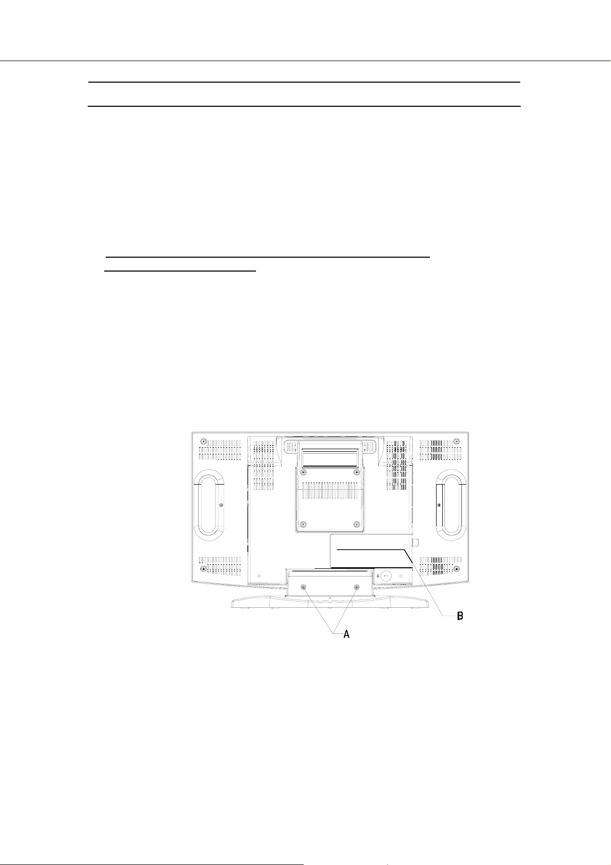
3) Swivel Base Removal :
3.1 Loosen 2 screws and remove Neck Cover . (Indicated as “A” )
3.2 Loosen 4 screws from Neck Bracket and remove the Swivel Base .
(Indicated as “C” )
4) Back Cover Removal :
4.1 Remove the Tuner Cover by pressing and sliding . (Indicated as “B”)
4.2 Loosen 6 screws from the Back Cover . (Indicated as “E” and “D”)
4.3 Lift up Back Cover and pull out the cable from the key board on the top of the panel .
-12-
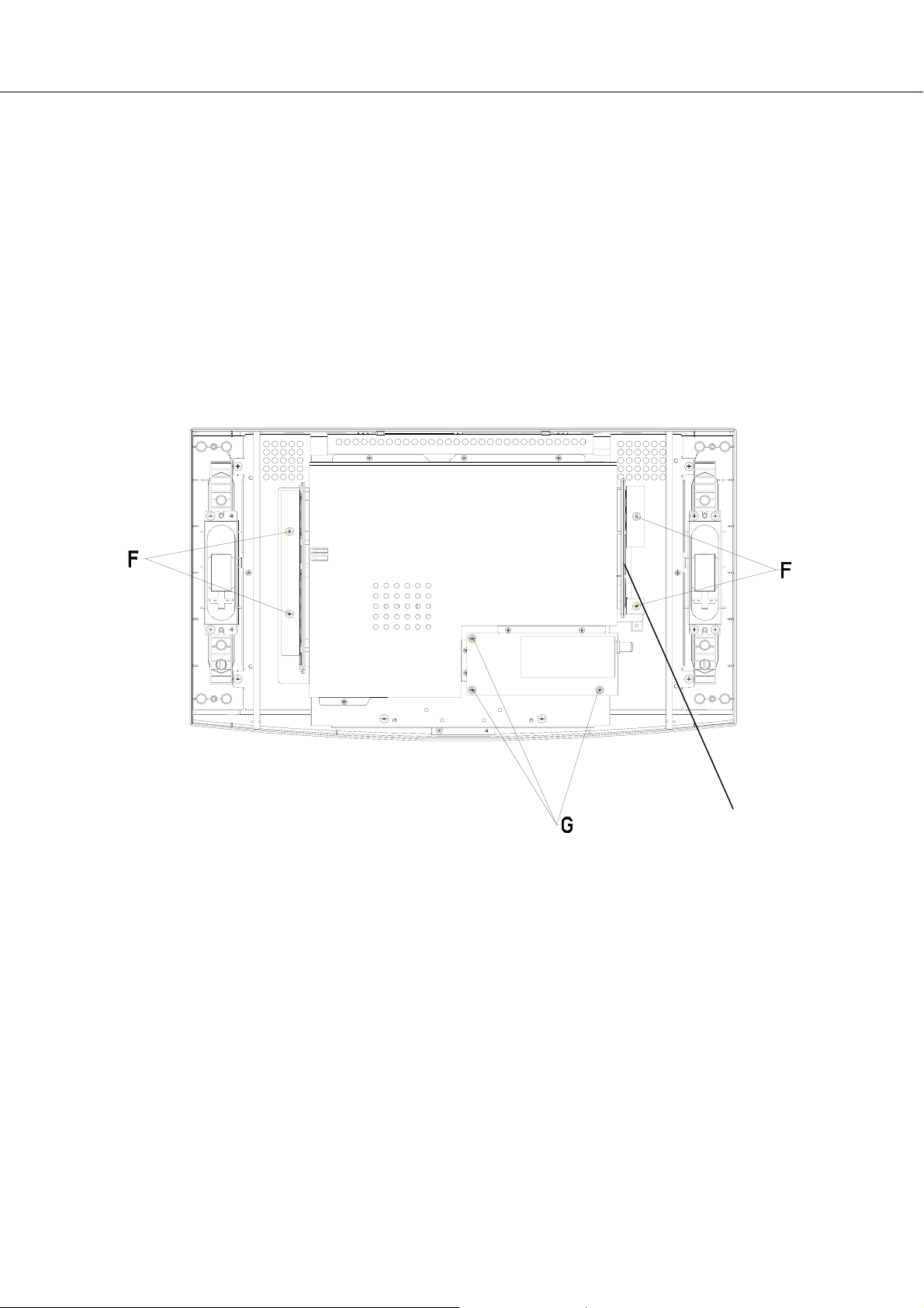
5) Right & Left Side Covers Removal :
5.1 Loosen 4 screws from Right & Left Side Covers . (Indicated as “F ”)
5.2 Loosen 2 screws from the 15 pin D-Sub connector on the right side of the panel.
(Indicated as “F’ ”)
5.3 Loosen 3 screws from the Tuner Board . (Indicated as “G ”)
5.4 Lift up the Tuner Board, and pull out the 15-pin cable .
.
F’
-13-

6) Metallic Shield Removal :
6.1 Loosen 8 screws from Metallic Shield of Main-PCB . (Indicated as “H”)
6.2 Remove Metallic Shield of Main-PCB from Main Bracket and then the
Main Board shows up.
I
7) MCU Removal (if need ) :
7.1 Clamp up the MCU by using an MCU clamp. (Indicated as “ I ”)
7.2 Put in new MCU and push fasten .
-14-

pply
Scart-Video
Scart-RGB
Component
AC Input
100~240V
50 / 60Hz
7. Block Diagram
Vid eo
S-Video
UT01
TV – Tuner
FQ1216 MK3
Video
Interlace
Progressive
PC VGA
Remote Control
Power
Su
SIF
Mono TV
I030
P15V330
+12
+ 12V
+ 8V
+ 5V
+ 2.5V
+ 3.3V
Video/S-V/ Component Audio
I029
TT Decorder
SAA5264PS
I018
Decorder
SAA7118E
I006
ADC
AD9883-110
I001
ADC
-
LED & IR Pad
Key Pad
EEPROM: 24C16
I013
4:1 Audio Processor
Scart Audio
MSP3410G
PC Audio
8 bit
24 bit Port B
24 bit Port A
-15-
I009
I019
Scale
TP6760
I012
MCU
SM59264C40
(SyncMOS)
r
I010
Audio Amp.
BA5417
TTL
16:9
INVERTER
3.5W + 3.5W
Speaker
Headphone Jack
Line-out (RCA)
Scart Audio Out
17”LCD
Panel
 Loading...