

Page 1
48V
A / B
LINE
/MIC
TRIM
RECORD
/EDIT
SELECT
ASSIGN
SELECT
INPUT 1
ON OFF
234567891011121
A BA BA BA BA BA BA BA BA BA BA B
123456789101112
0
+60
+600+600+600+600+600+600+600+600+600+600+60
+45
+45
+45
+45
+45
+45
+45
-15
-15
-15
-15
-15
SIGNAL / CLIP
SIGNAL / CLIP SIGNAL / CLIP SIGNAL / CLIP SIGNAL / CLIP SIGNAL / CLIP SIGNAL / CLIP SIGNAL / CLIP SIGNAL / CLIP SIGNAL / CLIP SIGNAL / CLIP SIGNAL / CLIP
23
1
123456789101112
567
13 14 15 16 17 18 19 20 21 22 23 24
-15
4567
8123
L / R 1 / 2 3 / 4 5 / 6 7 / 8
Q-CHANNEL
20Hz
L R
PAN
ON
SOLO SOLO SOLO SOLO SOLO SOLO SOLO SOLO SOLO SOLO SOLO SOLO
TRACK 1 / 13
2 / 14 3 / 15 4 / 16 5 / 17 6 / 18 7 / 19 8 / 20 9 / 21 10 / 22 11 / 23 12 / 24
20Hz
20kHz
20kHz
-
24dB
LOW
-
24dB
+
24dB
+
24dB
Q
SWEEP
23456789101112
GROUP 1 GROUP 2 GROUP 3 GROUP 4 GROUP 5 GROUP 6 GROUP 7 GROUP 8
-15
Q-STRIP
FUNCTION
20Hz
20kHz
-
HIGH
+45
-15
-15
812
456
FX / AUX 1 FX / AUX 2 FX / AUX 3 FX / AUX 4
PAN
PRE PRE PRE PRE EQ ON
FX / AUX 1 FX / AUX 2 FX / AUX 3 FX / AUX 4
24dB
+
24dB
FX RTN 1 FX RTN 2 FX RTN 3 FX RTN 4 L / R
LINE MICLINE MICLINE MICLINE MICLINE MICLINE MICLINE MICLINE MICLINE MICLINE MICLINE MIC
+45
+45
-15
-15
EFFECT / AUX SENDS
A B
LINE MIC
0
+45
+45
-15
34
78
MONITOR
LEVEL
MIN
!!SOLO!!
2-TRACK
MONO
NEAR
STUDIO CR
SELECT
TALK BACK
MASTER
MAX
CLIP
0
2
4
6
8
10
15
20
25
30
35
40
50
60
LR
TB
LEVEL
EXT
MAIN
SYNC
SCREEN
OFFSET
SHIFT
UNDO REDO PRE-ROLL AUTO
FADER BANK
INP
TRACKS
TRACKS
1-12
1-12
13-24
TO FROM IN OUT
OVER
REWIND FAST FORWARD STOP
5
5
F 1 F 2 F 3 F 4 F 5 F 6
HOURS MINS SECS FRAMES
BARS BEATS CLOCKS
SET
GROUP
USER
FX
BANK
AUTO LOCATE
GO TO
LOOP
MEMORY
ABORT
MIX SCENE
DISPLAY
SELECT
V
.
TRACK CD-RDSP PATCHGRID
RECALLSTORE
ENTERCANCEL
WHEELININP MON
LOCK
RELEASE
CONTRAST
SETUPPROJECTFXAUTOMATEMIXEREDIT
789
456
123
-
JOG SHUTTLE
Q 1
Q 2
Q 3
Q 4
Q 5
Q 6
CURSOR
ZOOM
+
0
OUT
DIGITAL PERSONAL STUDIO
SERVICE MANUAL
1
Page 2
##
#
SAFETY INSTRUCTIONS
##
##
# INFORMATIONS
##
1. Parts identified by the } symbol are critical for saf ety.
Replace them only with the parts number specified.
2. In addition to safety, other par ts and assemblies are
specified for conformance with such regulations as those
applying to spurious radiation.
These must also be replaced only with the specified
replacements.
Examples : Noise blocking capacitors, noise blocking filters ,
etc.
3. Use specified internal wiring. Note especially :
1) Wires covered with PVC tubing
2) Double insulated wires
3) High voltage leads
4. Use specified insulating materials for hazardous live parts.
Note especially :
1) Insulation Tape
2) PVC tubing
3) Spacers (insulating barriers)
4) Insulation sheets for transistors
5) Plastic screws for fixing micro switches
5. When replacing AC primary side components (transformers, power cords, noise b locking capacitors , etc.), wrap
the ends of the wires securely around the terminals before
soldering.
SYMBOLS FOR PRIMARY DESTINATION
Unit destinations are indicated with letters as shown below.
Symbols Principal Destinations
A U.S.A
B England
E Europe
J Japan
V
X1
X4
MAKE YOUR CONTRIBUTION TO PROTECT THE
ENVIRONMENT
Used batteries with the ISO symbol for recycling as
well as small accumulators (rechargeable batteries),
mini-batteries (cells) and starter batteries should not
be thrown into the garbage can.
Please leave them at an appropriate depot.
PRECAUTIONS FOR LITHIUM BATTERY
The lithium battery may explode when
[OBSERVE THE FOLLOEING WHEN REPLACING]
Germany
Japan
Universal Area
incorrectly replaced.
6. Make sure that wires do not contact heat producing parts
(heat sinks, oxide metal film resistors, fusible resistors,
etc.).
7. Check that replaced wires do not contact sharp edged or
pointed parts.
8. Also check areas surrounding repaired locations.
9. Make sure that foreign objects (screws, solder droplets,
etc.) do not remain inside the set.
SAFETY CHECK AFTER SERVICING
After servicing, make measurements of leakage-current or
resistance in order to determine that exposed parts are
acceptably insulated from the supply circuit. The leakagecurrent measurement should be done between accessible
metal parts (such as chassis, ground terminal, microphone
jacks, signal input/output connectors, etc.) and the earth ground
through a resistor of 1500 ohms paralleled with a 0.15 µF
capacitor, under the unit’s normal working conditions.
The leakage-current should be less than 0.5 mA rms AC. The
resistance measurement should be done between accessible
exposed metal parts and power cord plug prongs with the
power switch (if included) “ON”. The resistance should be
more than 2.2 M ohms.
• Replace with the same make and type or equivalent recom
mended by manufacturer.
• Place battery in correct polarity.
• Do not short the terminals.
• Do not charge battery.
• Do not dispose of battery in fire.
SERVICE MANUAL
2
Page 3

I. SPECIFICATIONS
Specifications
Power Supply AC 120V 60Hz (US, Canada), 220-240V 50Hz (Europe) 110W
Operating Temperature 10 - 35° C
Operating Humidity 10% - 60% (without condensation)
Dimensions (mm) 726 (W) x 190 (H) x 579 (D) max. (with LCD tilted down)
Weight 17.8kg (without drive)
Display 320 x 240 dots STN graphic LCD with back light
Sampling Rate 96kHz, 48kHz, 44.1kHz, 32kHz
Quantization Bit 24 bit/16 bit Linear
Recording Media Internal IDE Harddisk
Recording Time With 10Gbyte Harddisk drive (24bit)
FS=96kHz Approx. 9 hrs. 55 min. (12 tracks x 49 min. 45 sec.)
FS=48kHz Approx. 19 hrs. 50 min. (24 tracks x 49 min. 45 sec.)
FS=44.1kHz Approx. 21 hrs. 35 min. (24 tracks x 54 min. 10 sec.)
FS=32kHz Approx. 29 hrs. 50 min. (24 tracks x 1 hour 14 min.)
Frequency Response
FS=96kHz 10Hz - 44kHz +0/-2dB
FS=48kHz 10Hz - 22kHz +0/-2dB
FS=44.1kHz 10Hz - 20kHz +0/-2dB
FS=32kHz 10Hz - 15kHz +0/-2dB
ADC 24bit 128-times oversampling, enhanced dual bit delta/sigma modulation
DAC 24bit 8-times oversampling, advanced segment delta/sigma modulation
Dynamic Range 104dB or more (30kHz LPF, FS=44.1kHz)
Distortion Ratio 0.003% or less (1kHz, 44.1kHz)
Channel Crosstalk 80dB or less (10kHz referenced, 100 ohms terminated)
Wow & Flutter Below measurable level
Analog Audio Input Inputs A
1 - 4ch 6.3mm Stereo Phone/XLR Combo Jack - balanced
Phantom Power provided (switchable) for XLR connection
5 - 12ch 6.3mm Stereo Phone/XLR Combo Jack - balanced
Inputs B
1 - 12ch 6.3mm Stereo Phone Jack - balanced
Hi-Z 12ch 6.3mm Phone Jack - unbalanced
ADC In 6.3mm Stereo Phone Jack - balanced
AUX In 6.3mm Stereo Phone Jack - balanced
2-Track RCA - unbalanced
Input Level Mic mode -62 - -2dBu (+16dBu max. balanced, 1kHz)
Line mode -47 - +13dBu (+31dBu max. balanced, 1kHz)
Hi-Z -68 - -8dBu (+10dBu max. unbalanced, 1kHz)
ADC In +4dBu (+22dBu max. balanced, 1kHz)
AUX In +4dBu (+22dBu max. balanced, 1kHz)
2-Track -14dBu (+4dBu max. unbalanced, 1kHz)
Impedance Mic mode 3k ohms (1 - 12ch)
Line mode 12k ohms (1 - 12ch)
Hi-Z 1M ohms
ADC In 10k ohms
AUX In 10k ohms
2-Track 15k ohms
Analog Audio Output Stereo Out 6.3mm Stereo Phone - balanced
Main (monitor) 6.3mm Stereo Phone - balanced
Nearfield (monitor) 6.3mm Stereo Phone - balanced
Studio Out 6.3mm Stereo Phone - balanced
Direct Out 6.3mm Stereo Phone - balanced
AUX Sends 1 - 4 6.3mm Stereo Phone - balanced
SERVICE MANUAL
3
Page 4

Output Level Stereo Out +4dBu (+22dBu balanced max., 20k ohms load)
Main (monitor) +4dBu (+22dBu balanced max., 20k ohms load)
Nearfield (monitor) +4dBu (+22dBu balanced max., 20k ohms load)
Studio Out +4dBu (+22dBu balanced max., 20k ohms load)
Direct Out +4dBu (+22dBu balanced max., 20k ohms load)
AUX Sends 1 - 4 +4dBu (+22dBu balanced max., 20k ohms load)
Impedance Stereo Out 1k ohms - balanced
Main (monitor) 1k ohms - balanced
Nearfield (monitor) 1k ohms - balanced
Studio Out 1k ohms - balanced
Direct Out 1k ohms - balanced
AUX Sends 1 - 4 1k ohms - balanced
Stereo Phones Output x 2, 6.3mm Stereo Phone Jack - adjustable
Max. Output 155mW/32 ohms
Digital Audio Input x 1, RCA (SPDIF) 2-channels assignable
x 1, MP Light Pipe (adat/SPDIF) 8-channels/2-channel assignable
Digital Audio Output x 1, RCA (SPDIF) Master Output
x 1, MP Light Pipe (adat/SPDIF) 8-channels assignable/Master Output
Wordclock x 1, BNC - In/Out
Foot switch x 1, 6.3mm Phone Jack
MIDI x 3, 5 pin DIN - IN, OUT, THRU
ASCII Keyboard x 1, 6 pin Mini-DIN
Accessories 3-prong Power Cable
Internal Disk Mounting Kit
Operator’s Manual
Options IB-24LTC - SMPTE/EBU LTC Interface Board
IB-24ADT - 16-channel adat Interface Board w/adat Sync
IB-24SCSI - SCSI Interface Board
*0dBu = 0.775Vrms
The specifications are subject to change without prior notice.
SERVICE MANUAL
4
Page 5
II. DISASSEMBLY
In case of trouble, etc., necessitating dismantling, please dismantle in the order shown in the illustrations . Reassemb le in the
reverse order.
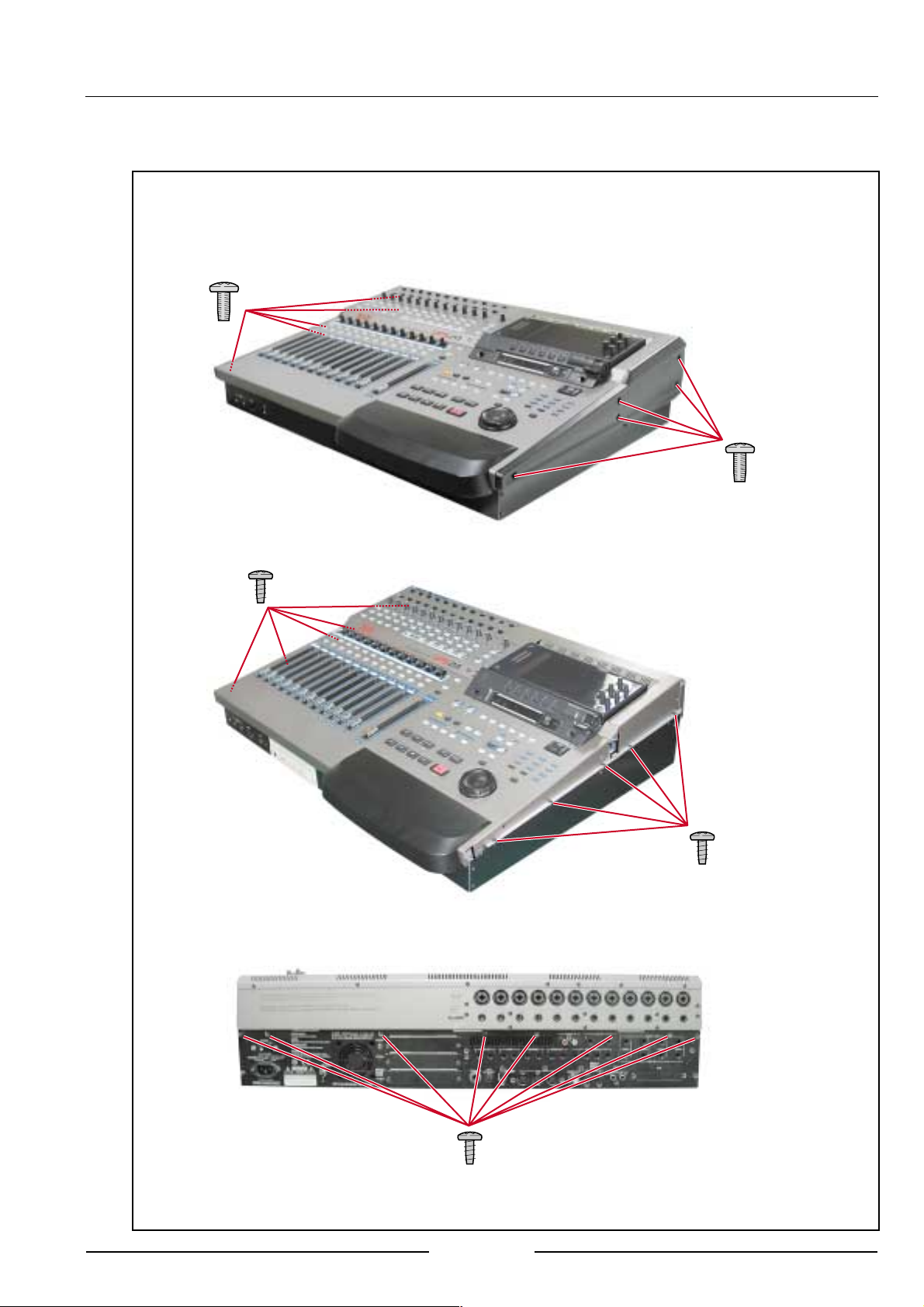
1. Removal of the FRONT PANEL BLOCK
ZS-378447
ST BID40X10STL BNI
ZS-378447
ST BID40X10STL BNI
ZS-331182
BT BID30X08STL BNI
ZS-331182
BT BID30X08STL BNI
ZS-331182
BT BID30X08STL BNI
SERVICE MANUAL
5
Page 6
ZS-331182
BT BID30X08STL BNI
ZS-331182
BT BID30X08STL BNI
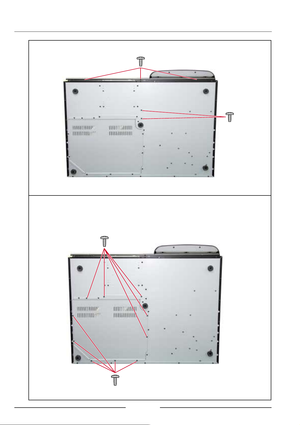
2. Removal of the BOTTOM COVER
ZS-331182
BT BID30X08STL BNI
ZS-331182
BT BID30X08STL BNI
SERVICE MANUAL
6
Page 7
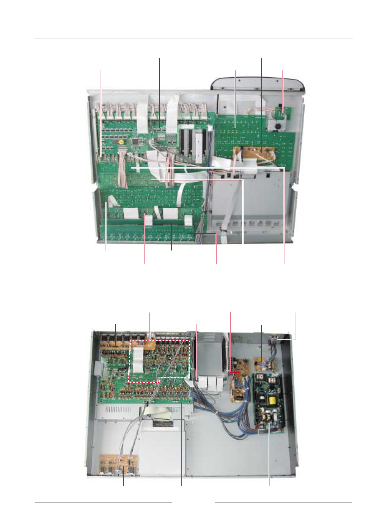
III. PRINCIPAL PARTS LOCATION
PC CONTROL BLK
PC OPERATION R BLKPC FADER BLK
PC OPE-DIST BLK
PC JOG BLK
PC OPERATION L BLK
PC PRE-AMP BLK PC INPUT B BLK
PC CPU BLK
PC AUX IN
PC INPUT A BLK
PC MOTHER BLK
PC LED PAN BLK
PC POWER BLK
PC FILTER BLK
PC PAN ENC BLK
POWER SW BLK
PC HP-HIZ BLK
PC ADDA BLK
SERVICE MANUAL
SW POWER BLK
7
Page 8

IV. SUPPLEMENTARY INFORMATION
1. Test Mode
While pressing the SHIFT button, press the CANCEL button to enter the DEBUG PAGE. To leave the DEBUG
page, press the MAIN SCREEN button. Return to the DEBUG PAGE from any TEST MODE by pressing the
CANCEL button while the SHIFT button is being pressed.
1-1. F1 (BUFFERS)
For confirmation of DISK BUFFERS LEVEL.
1-2. F3 (PANEL)
For confirmation of FADER TOUCH SENSE operation.
F1/F2 (RED TRACK LEDS)
To check whether red LED operation is correct or not.
The RECORD/EDIT SELECT LED, SIGNAL CLIP LED will light up in red.
All other LEDs will light.
F3/F4 (GREEN TRACK LEDS)
To check whether green LED operation is correct or not.
The RECORD/EDIT SELECT LED, SIGNAL CLIP LED will light up in green.
NOTE: After LED CHECK, even when the DEBUG mode has been escaped from, all LED indicators will go
out and only renewed modes will light up in order.
1-3. F4 (AUDIO)
The input AUDIO signal will be output to dircet according to display indicator specification. The main
purpose of this function is for factory testing.
1-4. F2 (MIX DSP) F6 (PATCH)
Not operational at V1.0.
2. PANEL OPERATION TEST MODE
This mode is operated by the OPERATION CPU and is not affected by the CPU circuit of the CPU PCB. This test
mode will operate even if the CPU PCB is not operating properly. Turn the power on while pressing down the
REWIND, FAST FORWARD, STOP and PLAY buttons.
This mode can be used to confirm correct operation of the SWITCH, FADER VR, MONITOR VR, JOG, SHUTTLE
and ENCODER. However, A/B SW, LINE/MIC SW, TRIM, TB LEVEL, PHONE LEVEL are omitted.
NOTE: FADER operation directly after power has been input cannot be tested.
3. OTHER HIDDEN MODES
3-1 With the SHUTTLE knob turned fully to the right, turning the power on will immediately access the VERSION
UP mode via the USB.
3-2 With the SHUTTLE knob turned fully to the left, turning the power on will boot up the system without
running a hard disc check.
This mode is convenient when the system will not startup because of hard disc data.
3-3 With the SHUTTLE knob turned 1/4 to the left, turning the power on will check hard disc content and start up
the system in PROJECT initial settings. Normally the DPS24 starts up in the last PROJECT created. This
mode is convenient when there is a problem with the last PROJECT data and the system won't start up.
SERVICE MANUAL
8
Page 9

4. JIG PC BOOT DPS24 (PART No. BA-771030J)
JIG PC BOOT is used for BOOT BLOCK recovery and for CPU circuit testing etc.
Insert in SLOT 1 on the OPTION BOARD. Make sure the power is off before inserting. The JIG PC BOOT will not
work in any other slot besides SLOT 1.
When the DPS24 power is turned on, the SELF CHECK function will operate to check each CHIP. If a fault is found
somewhere, FAILED will appear and operation will stop.
FAILED will appear when nothing after MIDI SPDIF, WCLK, ASCII are connected, but this is not an indication of
faulty operation.
5. OS BOOT BLOCK RECOVERY PROCEDURE
Insert the PC JIG BOOT into SLOT 1. Make sure the power is off before inserting. The JIG PC BOOT will not w ork
in any other slot besides SLOT 1.
1. When the DPS24 power is turned on, the SELF CHECK function will operate to check each CHIP. After confir-
mation, the screen will normally be returned to.
2. Press the SETUP button, then the F6(OS) button.
3. Press the F2/F3/F4 (upgrade from EPROM) button.
4. Press the F6(YES) button.
5. Press the F6(OK) button.
6. OS UPDATE PROCEDURE
• OS UPDATE FROM CD-ROM
You can update the OS from the built-in CD-ROM drive. Please use a CD-ROM that contains the OS for the
DPS24.
You can create the OS disc by using your PC's CD-R/W function to write the “DPS24.bin file” onto an ISO 9660
CD-ROM disc.
1. Turn the DPS24 on and insert the OS disc
2. Press the SETUP button, then the F6(OS) button.
3. Set “Update from” to “CD” with Q1 knob.
4. Press the F5/F6 (UPGRADE) button.
5. Confirm the displayed OS version. If not displayed, repeat the procedure.
6. If the correct version is displayed, press the F6(YES) button.
7. Press the F6 (OK) button.
8. Reboot the DPS24.
• OS UPDATE FROM USB
The OS update can be made from the PC via the USB port.
You must have the "OS Loader software for DPS24".
The following files are required for the update:
dps24usb.sys (USB set up file)
dps24usb.inf (USB set up file)
usbrom.exe (USB transmission software)
dps24.bin (OS file for DPS24)
These files must be placed in the same folder. (eg. c:\DPS24)
Installing the USB drivers:
1. Connect USB cable between DPS24 and PC.
2. Power up the PC and let it complete the boot up process.
3. Power up the DPS24.
SERVICE MANUAL
9
Page 10

4. Yous PC should automatically detect the DPS24 and open the New Hardware Wizard.
5. Choose the option in the New Hardware Wizard that allows you to specify the location of the driver files.
6. Ues the BROWSE function to locate the files expanded into the folder you created.
7. Click OK and next to install the drivers.
OS UPDATE FROM USB
1. Connect the DPS24 and PC with the USB cable.
2. Turn on the DPS24 and PC.
3. Press the DPS24's SETUP button, then the F6(OS) button.
4. Set “Upgrade from” to the USB port with Q1 knob.
5. Press the F5/F6(upgrade) button, then the F6(YES) button.
6. Wait for the OS to be loaded from the PC.
7. The OS Loader runs only using the MS-DOS Command prompt.
8. In the Command prompt window, switch to the folder you created. (eg. c:\DPS24)
9. Select the update type from the following. Normally select usbrom /v dps24.bin
#1. usbrom dps24.bin ------ (normal)
#2. usbrom /v dps24.bin ------ (update and checksum)
#3. usbrom /bootblock dps24.bin ------ (overwrite boot block)
Type in either of the above to execute the program.
10. Reboot the DPS24.
10
SERVICE MANUAL
Page 11

Installation of Options
IB-24LTC/IB-24ADT
1. Remove the screws for the cover of expansion slot and remove the cover. Save the screws.
2. Slide the Option Board in along the guide groove and press it firmly to ensure secure connection.
3. Tighten the screws back that have been removed in the previous step.
IB-24SCSI
1. From the bottom of the unit, remove the screws for the bottom cover and open the bottom.
2. Remove the screws for the cover of SCSI option slot on the Rear Panel and remove the cover. Save the
screws.
3. Place the board as illustrated, making sure that connectors are securely connected.
4. Mount the board with the screw included in the option board and with those screws removed previously.
5. Place the bottom cover back and tighten all screws.
SERVICE MANUAL
11
Page 12

Hard Disk Drive
1. From the bottom of the unit, remove the screws for the bottom cover and open the bottom.
2. Jumper setting of the hard disk has to be in MASTER mode with the short pin on the hard disk.
3. Referring to the illustration, slide the Hard Disk Drive in the disk holder and mount it with the screws inside
the Internal Disk Mounting Kit. There are inch-threaded screws and millimeter-threaded screws inside. Be
sure to use the appropriate type.
4. Connect the 4-pin Power Cable and 40-pin Disk Drive Cable as illustrated.
On the Disk Drive Cable, BLUE connector has to be connected to the CPU board on DPS24.
ZS-418538J
PAN N06-32UNCXSMM
STL CMT
5. Place the bottom cover back and tighten all screws.
12
SERVICE MANUAL
Page 13

CD-R/CD-RW Drive
1. From the bottom of the unit, remove the screws for the bottom cover and open the bottom.
2. Remove the cover for the CD-R/RW Drive on the Front Panel.
3. Jumper settingof the CD-R/RW has to be in SLAVE mode with short pin on the CD-R/RW.
4. Referring to the illustration, slide the CD-R/RW Drive from the front and mount it on the bottom chassis with
the screws inside the Internal Disk Mounting Kit. There are inch-threaded screws and millimeter-threaded
screws inside. Be sure to use the appropriate type.
5. Connect the 4-pin Power Cable and 40-pin Disk Drive Cable as illustrated.
On the Disk Drive Cable, BLUE connector has to be connect to the CPU board on DPS24.
6. Place the bottom cover back and tighten all screws.
SERVICE MANUAL
13
Page 14

V. PARTS LIST
ATTENTION
1. When placing an order for parts, be sure to list the Part No., Model No. and the description of each part.
Otherwise, the non-delivery of the part or the delivery of a wrong part may result.
2. Please make sure that Part No. is correct when ordering.
If not, a part different from the one you ordered may be delivered.
3. Since the parts shown in Parts List or Preliminary Service Manual may have been the subject of changes,
please use this Parts List for all future reference.
HOW TO USE THIS PARTS LIST
1. This Parts List lists those parts which are considered necessary for repairs.
2. Parts not shown in the Parts List will not in principle be supplied.
3. How to read the Parts List.
1. PC MAIN BOARD BLK
Ref. No. Part No. Description
D5 ED-431276C D SCHOT 1S30-J T05
D110 ED-431276C D SCHOT 1S30-J T05
:
:
IC5 EI-811073J ICTRC-6593
IC10 EI-811068J IC HD74HC157FP
Service parts classification
These reference symbols correspond with component
symbols in the Schematic Diagrams.
2. FINAL ASSEMBLY BLK
Ref. No. Part No. Description
1. SA-349332 FOOT
2. ZS-344754C ST PAN30x06STL CMT
:
:
44. SP-417333J COVER TOP
45. ZS-418385J BT BID30X06STL BNI EATRH LOCK
46-A EW-380905J AC CORD 250S KP300 KS16A
H B J [J]
46-B EW-368420J1 AC CORD 200SKP30KS B AC [A]
46-C EW-410608J AC CORD 250 KP4819D KS31A B E
[E,V]
Symbols for primary destination
[A] U.S.A. [J] Japan
[B] England [V] Germany
[E] Europe [x1] Japan
[X4] Universal Area
Safety critical component
This number corresponds with the individual parts index number
in the figure.
WARNING
}}
} INDICATES SAFETY CRITICAL COMPONENTS. FOR CONTINUED SAFETY, REPLACE SAFETY CRITICAL
}}
COMPONENTS ONLY WITH MANUFACTURER'S RECOMMENDED PARTS.
AVERTISSEMENT
}}
} IL INDIQUE LES COMPOSANTS CRITIQUES DE SÉCURITÉ. POUR MAINTENIR LE DEGRÉ DE SÉCURITÉDE
}}
L'APPAREIL, NE REMPLACER QUE DES PIÉCES RECOMMANDEES PAR LÉ FABRICANT.
SERVICE MANUAL
14
Page 15

PC BOARD BLK
The PC Board Block may contain se veral PC Boards. The y appear
under its block name with their individual part number.
1. P.C.BOARD BLK
Ref.No Part No. Description
1 BA-L3056A020A PC CPU BLK DPS24
2 BA-L3056A030A PC(#)ADDA BLK DPS24
3 BA-L3056A040A PC(#)CONTROL BLK DPS24
4 BA-L3056A050A PC(#)OPE R BLK DPS24
5 BA-L3056A060A PC(#)OPE L BLK DPS24
6 BA-L3056A070A PC(#)IO BLK DPS24
7 BA-L3056A080A PC(#)FADER BLK DPS24
PC(#)ADDA BLK DPS24 CONSISTIS OF FOLLOWING P.C.BOARD
Part No. Description
BA-L3056A502A PC ADDA BLK
BA-L3056A502B PC PAN ENC BLK
PC(#)CONTROL BLK DPS24 CONSISTIS OF FOLLOWING P.C.BOARDS
Part No. Description
BA-L3056A503A PC CONTROL BLK
BA-L3056A503B PC PRE-AMP BLK
BA-L3056A503C PC MOTHER BLK
PC(#)OPE R BLK DPS24 CONSISTIS OF FOLLOWING P.C.BOARDS
Part No. Description
BA-L3056A504A PC OPERATION R BLK
BA-L3056A504B PC 7 SEG BLK
BA-L3056A504C PC LCD-DIST BLK
BA-L3056A504D PC FILTER BLK
BA-L3056A504E PC Q-LINK BLK
BA-L3056A504F PC METER BLK
BA-L3056A504G PC MIC BLK
PC(#)OPE L BLK DPS24 CONSISTIS OF FOLLOWING P.C.BOARDS
Part No. Description
BA-L3056A505A PC LED PAN BLK
BA-L3056A505B PC OPERATION L BLK
BA-L3056A505C PC AUX-IN BLK
BA-L3056A505D PC OPE-DIST BLK
BA-L3056A505E PC JOG BLK
PC(#)IO BLK DPS24 CONSISTIS OF FOLLOWING P.C.BOARDS
Part No. Description
BA-L3056A506A PC INPUT A BLK
BA-L3056A506B PC INPUT B BLK
BA-L3056A506C PC POWER BLK
BA-L3056A506D PC HP-HIZ BLK
PC(#)FADER BLK DPS24 CONSISTIS OF FOLLOWING P.C.BOARDS
Part No. Description
BA-L3056A507A PC FADER BLK
2. P.C. CPU BLK
Ref.No Part No. Description
J1 EJ-821219X PHONE J YKB22-5244 NUT 6.3
J2 EJ-403478J DIN J YKF51-5040 5P
J3 EJ-821236X SOCKET CONNECTER YKF45-0020 4P
J4 EJ-810323J SOCKET TCS7927-56
J5 EJ-820150J SOCKET COAX. BNC-LNRD-BPAA
J6 EJ-394490J SOCKET OPTICAL GP1F32T
J7 EJ-394459J SOCKET OPTICAL GP1F32R
J8 EJ-820754X PIN J YKC21-3079 P2P
J9 EJ-820493X SOCKET BATTERY BH25TN
BT1
J201 EJ-821170X SOCKET 20FMZ-BT 20P
J202 EJ-812021J SOCKET 26FMZ-BT 26P
J203 EJ-821171X SOCKET 28FMZ-BT 28P
J301 EJ-820809X SOCKET 40FE-BT-VK-N 40P
P11 EJ-820807X PLUG 128A-050P2A-L14A 50P
P101 EJ-821378X PLUG 302-40GSB-ATA 40P
P102 EJ-811058J PLUG 302-16GSB 16P
SF9 EF-811099J FUSE RXE030 60V 0.30A
D1 ED-428998J D SILICON C.1SS355TE-17 T08E
D2 ED-428998J D SILICON C.1SS355TE-17 T08E
D3 ED-428998J D SILICON C.1SS355TE-17 T08E
D5 ED-812338J D ZENER C.UDZ4.7BTE-17 T08E
D6 ED-428998J D SILICON C.1SS355TE-17 T08E
D7 ED-428998J D SILICON C.1SS355TE-17 T08E
IC1 EI-820788X IC GDS1110BD-206MHZ MBGA [unavailable]
IC2 EI-820802X IC XC2S150-5FG256C MBGA [unavailable]
IC3 EI-812794J IC XCB56362PV100 TQFP
IC4 EI-812794J IC XCB56362PV100 TQFP
IC5 EI-812794J IC XCB56362PV100 TQFP
IC6 EI-821487X IC HY57V641620HGT-P
IC7 EI-821487X IC HY57V641620HGT-P
IC8 EI-821487X IC HY57V641620HGT-P
IC9 EI-821487X IC HY57V641620HGT-P
IC10 EI-812979J IC HD74LVC245ATELL FPELT16E
IC11 EI-812979J IC HD74LVC245ATELL FPELT16E
IC12 EI-812978J IC HD74LVC541ATELL FPELT16E
IC13 EI-812978J IC HD74LVC541ATELL FPELT16E
IC14 EI-820787X IC GAL16V8D-15QP L3056
IC15 EI-820062J IC HD74HCT541FP FPELT24
IC16 EI-812979J IC HD74LVC245ATELL FPELT16E
IC17 EI-812979J IC HD74LVC245ATELL FPELT16E
IC18 EI-820795X IC HD74LVC14TELL FPELT12E
IC19 EI-820794X IC HD74LVC138TELL FPELT12E
IC20 EI-820792X IC HD74LS08FP FPELT16E
IC21 EI-811096J IC HD74HC4053FP
IC22 EI-438820J IC TC74HCU04AF FPEL T16E
IC23 EI-820154J IC CS8420-CS FP
IC24 EI-810887J IC AV9173-01CS08 FP T12E
IC25 EI-810574J IC M51957BFP FP73AT12
IC26 EI-820800X IC RS5C313
IC28 EI-821406X IC AIC1117CE FP T16E
IC29 EI-821406X IC AIC1117CE FP T16E
IC30 EI-820801X IC TE28F160C3BA90
IC31 EI-812978J IC HD74LVC541ATELL FPELT16E
IC32 EI-812978J IC HD74LVC541ATELL FPELT16E
IC33 EI-812978J IC HD74LVC541ATELL FPELT16E
IC34 EI-812978J IC HD74LVC541ATELL FPELT16E
IC35 EI-812978J IC HD74LVC541ATELL FPELT16E
IC36 EI-820793X IC HD74LVC125ATELL FPELT12E
IC37 EI-820955X IC NET2890
IC51 EI-812794J IC XCB56362PV100 TQFP
IC52 EI-812852J IC TC55V16256J-15
IC53 EI-812852J IC TC55V16256J-15
IC54 EI-820459X IC GM71VS65163CLT-5
IC55 EI-820459X IC GM71VS65163CLT-5
PH1 ET-431258J DETECTOR C.PC400T T12E
EZ-811066J BATTERY LITHIUM CR2025
SERVICE MANUAL
15
Page 16

Ref.No Part No. Description
T1 BT-810651J TRANS PULSE CIT0705S-35101TFP
TR1 ET-820772X TR CHIP DTB122JKT146 T08E
TR2 ET-821162X TR CHIP DTC343TKT146 T08E
TR3 ET-433976J TR C.DTA114TKA T146T08E
X1 EI-820769X OSC X’TAL C.SMD-49 3.6864MHZ
X2 EI-820827X OSC X’TAL C.SG8002JAPCB 50MHZ
X3 EI-427850J OSC X’TAL MC306 32.768KHZ
X4 EI-821163X OSC X’TAL C.SG8002JAPCB 48MHZ
3. P.C. (#)ADDA BLK
P.C. ADDA BLK
Ref.No Part No. Description
D601 ED-811455J D SILICON H 1SS133T-77 T26
D602 ED-811455J D SILICON H 1SS133T-77 T26
D603 ED-811455J D SILICON H 1SS133T-77 T26
D604 ED-811455J D SILICON H 1SS133T-77 T26
D605 ED-811455J D SILICON H 1SS133T-77 T26
D606 ED-811455J D SILICON H 1SS133T-77 T26
D607 ED-811455J D SILICON H 1SS133T-77 T26
D608 ED-811455J D SILICON H 1SS133T-77 T26
D609 ED-811455J D SILICON H 1SS133T-77 T26
D610 ED-811455J D SILICON H 1SS133T-77 T26
D611 ED-811455J D SILICON H 1SS133T-77 T26
D612 ED-811455J D SILICON H 1SS133T-77 T26
IC11 EI-810591J IC NJM5532L
IC12 EI-810591J IC NJM5532L
IC31 EI-810591J IC NJM5532L
IC32 EI-810591J IC NJM5532L
IC33 EI-812318J IC AK5393-VS
IC51 EI-810591J IC NJM5532L
IC52 EI-810591J IC NJM5532L
IC71 EI-810591J IC NJM5532L
IC72 EI-810591J IC NJM5532L
IC73 EI-812318J IC AK5393-VS
IC91 EI-810591J IC NJM5532L
IC92 EI-810591J IC NJM5532L
IC111 EI-810591J IC NJM5532L
IC112 EI-810591J IC NJM5532L
IC113 EI-812318J IC AK5393-VS
IC131 EI-810591J IC NJM5532L
IC132 EI-810591J IC NJM5532L
IC134 EI-384806J IC TC74HC4053AP
IC151 EI-810591J IC NJM5532L
IC152 EI-810591J IC NJM5532L
IC153 EI-812318J IC AK5393-VS
IC154 EI-384806J IC TC74HC4053AP
IC171 EI-810591J IC NJM5532L
IC172 EI-810591J IC NJM5532L
IC191 EI-810591J IC NJM5532L
IC192 EI-810591J IC NJM5532L
IC193 EI-812318J IC AK5393-VS
IC211 EI-810591J IC NJM5532L
IC212 EI-810591J IC NJM5532L
IC231 EI-810591J IC NJM5532L
IC232 EI-810591J IC NJM5532L
IC233 EI-812318J IC AK5393-VS
IC251 EI-810591J IC NJM5532L
IC252 EI-810591J IC NJM5532L
IC271 EI-810591J IC NJM5532L
IC272 EI-810591J IC NJM5532L
IC273 EI-812318J IC AK5393-VS
IC291 EI-810591J IC NJM5532L
IC292 EI-810591J IC NJM5532L
IC311 EI-810591J IC NJM5532L
IC312 EI-810591J IC NJM5532L
IC313 EI-812318J IC AK5393-VS
Ref.No Part No. Description
IC331 EI-810591J IC NJM5532L
IC332 EI-810591J IC NJM5532L
IC333 EI-821226X IC OPA2134UA FPT12E
IC345 EI-820799X IC PCM1738E FPT16E
IC352 EI-810591J IC NJM5532L
IC353 EI-821226X IC OPA2134UA FPT12E
IC371 EI-810591J IC NJM5532L
IC372 EI-810591J IC NJM5532L
IC373 EI-821226X IC OPA2134UA FPT12E
IC385 EI-820799X IC PCM1738E FPT16E
IC392 EI-810591J IC NJM5532L
IC393 EI-821226X IC OPA2134UA FPT12E
IC411 EI-810591J IC NJM5532L
IC412 EI-810591J IC NJM5532L
IC413 EI-821226X IC OPA2134UA FPT12E
IC425 EI-820799X IC PCM1738E FPT16E
IC432 EI-810591J IC NJM5532L
IC433 EI-821226X IC OPA2134UA FPT12E
IC451 EI-810591J IC NJM5532L
IC452 EI-810591J IC NJM5532L
IC453 EI-821226X IC OPA2134UA FPT12E
IC465 EI-820799X IC PCM1738E FPT16E
IC472 EI-810591J IC NJM5532L
IC473 EI-821226X IC OPA2134UA FPT12E
IC491 EI-810591J IC NJM5532L
IC492 EI-810591J IC NJM5532L
IC493 EI-821226X IC OPA2134UA FPT12E
IC505 EI-820799X IC PCM1738E FPT16E
IC512 EI-810591J IC NJM5532L
IC513 EI-821226X IC OPA2134UA FPT12E
IC531 EI-431241J IC HD74HC4052FP FPELT16E
IC532 EI-810591J IC NJM5532L
IC551 EI-403306J IC NJM4558L
IC552 EI-810591J IC NJM5532L
IC601 EI-820951X IC HD74LVC244AT FPELT16E
IC602 EI-810589J IC M51957BL
IC603 EI-431115J IC HD74HC595FP FPELT16E
IC604 EI-431115J IC HD74HC595FP FPELT16E
IC605 EI-413206J IC NJM7905FA
IC606 EI-820780X IC AIC1117-33CE
IC607 EI-812977J IC HD74LVC08TELL FPELT16E
IC608 EI-431241J IC HD74HC4052FP FPELT16E
IC609 EI-810591J IC NJM5532L
IC610 EI-820793X IC HD74LVC125ATELL FPELT12E
J1 EJ-821223X PHONE J YKB26-5312 S.NUT 6.3
J2 EJ-821223X PHONE J YKB26-5312 S.NUT 6.3
J3 EJ-821223X PHONE J YKB26-5312 S.NUT 6.3
J4 EJ-821223X PHONE J YKB26-5312 S.NUT 6.3
J203 EJ-821170X SOCKET 20FMZ-BT 20P
J301 EJ-820809X SOCKET 40FE-BT-VK-N 40P
J303 EJ-821169X SOCKET 13FMZ-BT 13P
J304 EJ-821169X SOCKET 13FMZ-BT 13P
J306 EJ-427802J SOCKET 26FE-BT 26P
J331 EJ-821222X PHONE J YKB26-5257 S.NUT 6.3
J351 EJ-821222X PHONE J YKB26-5257 S.NUT 6.3
J371 EJ-821222X PHONE J YKB26-5257 S.NUT 6.3
J391 EJ-821222X PHONE J YKB26-5257 S.NUT 6.3
J411 EJ-821222X PHONE J YKB26-5257 S.NUT 6.3
J431 EJ-821222X PHONE J YKB26-5257 S.NUT 6.3
J451 EJ-821222X PHONE J YKB26-5257 S.NUT 6.3
J471 EJ-821222X PHONE J YKB26-5257 S.NUT 6.3
J491 EJ-821222X PHONE J YKB26-5257 S.NUT 6.3
J511 EJ-821222X PHONE J YKB26-5257 S.NUT 6.3
J531 EJ-821222X PHONE J YKB26-5257 S.NUT 6.3
J551 EJ-821222X PHONE J YKB26-5257 S.NUT 6.3
RP601 ER-386637J COMP R RGLE8X 103J
SF7
EF-376821 FUSE ICP-N15 50V 0.6A
16
SERVICE MANUAL
Page 17

Ref.No Part No. Description
TR131 ET-362847 TR 2SA1317 S,T,U T05
TR132 ET-362209 TR 2SC3330 S,T,U T05
TR151 ET-362847 TR 2SA1317 S,T,U T05
TR152 ET-362209 TR 2SC3330 S,T,U T05
TR331 ET-820770X TR 2SD2227S T05
TR332 ET-820770X TR 2SD2227S T05
TR351 ET-820770X TR 2SD2227S T05
TR352 ET-820770X TR 2SD2227S T05
TR371 ET-820770X TR 2SD2227S T05
TR372 ET-820770X TR 2SD2227S T05
TR391 ET-820770X TR 2SD2227S T05
TR392 ET-820770X TR 2SD2227S T05
TR411 ET-820770X TR 2SD2227S T05
TR412 ET-820770X TR 2SD2227S T05
TR431 ET-820770X TR 2SD2227S T05
TR432 ET-820770X TR 2SD2227S T05
TR451 ET-820770X TR 2SD2227S T05
TR452 ET-820770X TR 2SD2227S T05
TR471 ET-820770X TR 2SD2227S T05
TR472 ET-820770X TR 2SD2227S T05
TR491 ET-820770X TR 2SD2227S T05
TR492 ET-820770X TR 2SD2227S T05
TR511 ET-820770X TR 2SD2227S T05
TR512 ET-820770X TR 2SD2227S T05
TR531 ET-820770X TR 2SD2227S T05
TR532 ET-820770X TR 2SD2227S T05
TR551 ET-820770X TR 2SD2227S T05
TR552 ET-820770X TR 2SD2227S T05
TR601 ET-389684J TR DTA113ZS T05
TR602 ET-389684J TR DTA113ZS T05
TR603 ET-389684J TR DTA113ZS T05
TR604 ET-820770X TR 2SD2227S T05
TR605 ET-820770X TR 2SD2227S T05
TR606 ET-389684J TR DTA113ZS T05
TR607 ET-389684J TR DTA113ZS T05
TR608 ET-820770X TR 2SD2227S T05
TR609 ET-820770X TR 2SD2227S T05
TR610 ET-820770X TR 2SD2227S T05
TR611 ET-820770X TR 2SD2227S T05
TR612 ET-364023 TR DTC114ES T05
TR613 ET-389684J TR DTA113ZS T05
TR614 ET-364023 TR DTC114ES T05
TR615 ET-389684J TR DTA113ZS T05
W313 EW-820715X WIRE ASSY L3056 W313 6P
P.C. PAN ENC BLK
IC801 EI-820790X IC HD74HC253FP FPELT16E
IC802 EI-820790X IC HD74HC253FP FPELT16E
IC803 EI-820790X IC HD74HC253FP FPELT16E
J409 EJ-438452J SOCKET 10-FMZ-ST 10P
SW801 ES-812749J SW ROTARY ENCORDER EC12E24204
SW802 ES-812749J SW ROTARY ENCORDER EC12E24204
SW803 ES-812749J SW ROTARY ENCORDER EC12E24204
SW804 ES-812749J SW ROTARY ENCORDER EC12E24204
SW805 ES-812749J SW ROTARY ENCORDER EC12E24204
SW806 ES-812749J SW ROTARY ENCORDER EC12E24204
SW807 ES-812749J SW ROTARY ENCORDER EC12E24204
SW808 ES-812749J SW ROTARY ENCORDER EC12E24204
SW809 ES-812749J SW ROTARY ENCORDER EC12E24204
SW810 ES-812749J SW ROTARY ENCORDER EC12E24204
SW811 ES-812749J SW ROTARY ENCORDER EC12E24204
SW812 ES-812749J SW ROTARY ENCORDER EC12E24204
4. P.C. (#)CONTROL BLK
P.C. CONTROL BLK
Ref.No Part No. Description
D701 ED-821003X D SILICON C. DAN217 T146T08
D702 ED-428998J D SILICON C.1SS355TE-17 T08E
D703 ED-821003X D SILICON C. DAN217 T146T08
IB701 ER-813231J COMP R C.MNR14 472J T08P
IB702 ER-813231J COMP R C.MNR14 472J T08P
IB703 ER-813231J COMP R C.MNR14 472J T08P
IB704 ER-813231J COMP R C.MNR14 472J T08P
IB705 ER-813231J COMP R C.MNR14 472J T08P
IC701 EI-820798X IC MB91110PMT2-G-BND QFTY
IC702 EI-811086J IC HD74HC541FP
IC703 EI-401216J IC HD74HC138FP
IC704 EI-820789X IC HD74HC238FP FPELT16E
IC705 EI-820789X IC HD74HC238FP FPELT16E
IC706 EI-812482J IC HD74HC4051FP
IC707 EI-431253J IC HD74HC14FP FPELT16E
IC708 EI-811577J IC HD74HC175FP FPELT16E
IC709 EI-820796X IC LMC555CMX FP T12E
IC710 EI-401216J IC HD74HC138FP
IC711 EI-401216J IC HD74HC138FP
IC712 EI-401216J IC HD74HC138FP
IC713 EI-401216J IC HD74HC138FP
IC714 EI-810268J IC HD74HC273FP
IC715 EI-810268J IC HD74HC273FP
IC716 EI-810268J IC HD74HC273FP
IC717 EI-811577J IC HD74HC175FP FPELT16E
IC718 EI-811577J IC HD74HC175FP FPELT16E
IC719 EI-812482J IC HD74HC4051FP
IC720 EI-812482J IC HD74HC4051FP
IC721 EI-820786X IC TLC2272CDR FP T16E
IC722 EI-820791X IC HD74HC86FP FPELT16E
IC723 EI-821405X IC AIC1117-33CE FP T16E
IC724 EI-431115J IC HD74HC595FP FPELT16E
IC725 EI-431115J IC HD74HC595FP FPELT16E
IC726 EI-431115J IC HD74HC595FP FPELT16E
IC727 EI-821440X IC M27C256B45XF1 DPS24 V1.0-OP
IC801 EI-820782X IC BA6286N
IC802 EI-820782X IC BA6286N
IC803 EI-820782X IC BA6286N
IC804 EI-820782X IC BA6286N
IC805 EI-820782X IC BA6286N
IC806 EI-820782X IC BA6286N
IC807 EI-820782X IC BA6286N
IC808 EI-820782X IC BA6286N
IC809 EI-820782X IC BA6286N
IC810 EI-820782X IC BA6286N
IC811 EI-820782X IC BA6286N
IC812 EI-820782X IC BA6286N
IC813 EI-820782X IC BA6286N
J401 EJ-821389X SOCKET 26FE-BT-VK-N 26P
J402 EJ-820808X SOCKET 20FE-BT-VK-N 20P
J403 EJ-821389X SOCKET 26FE-BT-VK-N 26P
J409 EJ-820815X SOCKET 10FMZ-BT 10P
J410 EJ-821389X SOCKET 26FE-BT-VK-N 26P
SF10 EF-376821 FUSE ICP-N25 50V 0.6A
TR701 ET-820771X TR FET CHIP 2SK2103T100 T12E
TR702 ET-820771X TR FET CHIP 2SK2103T100 T12E
TR703 ET-820771X TR FET CHIP 2SK2103T100 T12E
TR704 ET-820771X TR FET CHIP 2SK2103T100 T12E
TR705 ET-820771X TR FET CHIP 2SK2103T100 T12E
TR706 ET-820771X TR FET CHIP 2SK2103T100 T12E
TR707 ET-820771X TR FET CHIP 2SK2103T100 T12E
TR708 ET-820771X TR FET CHIP 2SK2103T100 T12E
TR709 ET-820771X TR FET CHIP 2SK2103T100 T12E
TR710 ET-820771X TR FET CHIP 2SK2103T100 T12E
TR711 ET-820771X TR FET CHIP 2SK2103T100 T12E
SERVICE MANUAL
17
Page 18

Ref.No Part No. Description
TR712 ET-820771X TR FET CHIP 2SK2103T100 T12E
TR713 ET-820771X TR FET CHIP 2SK2103T100 T12E
TR714 ET-820771X TR FET CHIP 2SK2103T100 T12E
TR715 ET-820771X TR FET CHIP 2SK2103T100 T12E
TR716 ET-820771X TR FET CHIP 2SK2103T100 T12E
TR717 ET-820771X TR FET CHIP 2SK2103T100 T12E
TR718 ET-820771X TR FET CHIP 2SK2103T100 T12E
TR719 ET-820771X TR FET CHIP 2SK2103T100 T12E
TR720 ET-820771X TR FET CHIP 2SK2103T100 T12E
TR721 ET-820771X TR FET CHIP 2SK2103T100 T12E
TR722 ET-820771X TR FET CHIP 2SK2103T100 T12E
TR723 ET-820771X TR FET CHIP 2SK2103T100 T12E
TR724 ET-820771X TR FET CHIP 2SK2103T100 T12E
TR725 ET-820771X TR FET CHIP 2SK2103T100 T12E
TR726 ET-439329J TR C.DTA143ZKA T146T08E
TR727 ET-439329J TR C.DTA143ZKA T146T08E
TR728 ET-439329J TR C.DTA143ZKA T146T08E
TR729 ET-439329J TR C.DTA143ZKA T146T08E
TR730 ET-439329J TR C.DTA143ZKA T146T08E
TR731 ET-439329J TR C.DTA143ZKA T146T08E
TR732 ET-439329J TR C.DTA143ZKA T146T08E
TR733 ET-439329J TR C.DTA143ZKA T146T08E
TR734 ET-439329J TR C.DTA143ZKA T146T08E
TR735 ET-439329J TR C.DTA143ZKA T146T08E
TR736 ET-439329J TR C.DTA143ZKA T146T08E
TR737 ET-439329J TR C.DTA143ZKA T146T08E
TR738 ET-439329J TR C.DTA143ZKA T146T08E
TR739 ET-439329J TR C.DTA143ZKA T146T08E
TR740 ET-439329J TR C.DTA143ZKA T146T08E
TR741 ET-439329J TR C.DTA143ZKA T146T08E
TR742 ET-439329J TR C.DTA143ZKA T146T08E
TR743 ET-439329J TR C.DTA143ZKA T146T08E
TR744 ET-439329J TR C.DTA143ZKA T146T08E
TR745 ET-439329J TR C.DTA143ZKA T146T08E
TR746 ET-439329J TR C.DTA143ZKA T146T08E
TR747 ET-439329J TR C.DTA143ZKA T146T08E
TR748 ET-439329J TR C.DTA143ZKA T146T08E
TR749 ET-439329J TR C.DTA143ZKA T146T08E
TR750 ET-439329J TR C.DTA143ZKA T146T08E
TR751 ET-439329J TR C.DTA143ZKA T146T08E
TR752 ET-439329J TR C.DTA143ZKA T146T08E
TR753 ET-439329J TR C.DTA143ZKA T146T08E
TR754 ET-439329J TR C.DTA143ZKA T146T08E
TR755 ET-439329J TR C.DTA143ZKA T146T08E
TR756 ET-439329J TR C.DTA143ZKA T146T08E
TR757 ET-439329J TR C.DTA143ZKA T146T08E
TR758 ET-439329J TR C.DTA143ZKA T146T08E
TR759 ET-439329J TR C.DTA143ZKA T146T08E
X701 EI-820768X OSC X’TAL C.SMD-49 12.500MHZ
P.C. PRE-AMP BLK
D1 ED-811455J D SILICON H 1SS133T-77 T26
D2 ED-811455J D SILICON H 1SS133T-77 T26
D3 ED-811455J D SILICON H 1SS133T-77 T26
D4 ED-811455J D SILICON H 1SS133T-77 T26
D5 ED-811455J D SILICON H 1SS133T-77 T26
D6 ED-811455J D SILICON H 1SS133T-77 T26
D51 ED-811455J D SILICON H 1SS133T-77 T26
D52 ED-811455J D SILICON H 1SS133T-77 T26
D53 ED-811455J D SILICON H 1SS133T-77 T26
D54 ED-811455J D SILICON H 1SS133T-77 T26
D55 ED-811455J D SILICON H 1SS133T-77 T26
D56 ED-811455J D SILICON H 1SS133T-77 T26
D101 ED-811455J D SILICON H 1SS133T-77 T26
D102 ED-811455J D SILICON H 1SS133T-77 T26
D103 ED-811455J D SILICON H 1SS133T-77 T26
D104 ED-811455J D SILICON H 1SS133T-77 T26
Ref.No Part No. Description
D105 ED-811455J D SILICON H 1SS133T-77 T26
D106 ED-811455J D SILICON H 1SS133T-77 T26
D151 ED-811455J D SILICON H 1SS133T-77 T26
D152 ED-811455J D SILICON H 1SS133T-77 T26
D153 ED-811455J D SILICON H 1SS133T-77 T26
D154 ED-811455J D SILICON H 1SS133T-77 T26
D155 ED-811455J D SILICON H 1SS133T-77 T26
D156 ED-811455J D SILICON H 1SS133T-77 T26
D201 ED-811455J D SILICON H 1SS133T-77 T26
D202 ED-811455J D SILICON H 1SS133T-77 T26
D203 ED-811455J D SILICON H 1SS133T-77 T26
D204 ED-811455J D SILICON H 1SS133T-77 T26
D205 ED-811455J D SILICON H 1SS133T-77 T26
D206 ED-811455J D SILICON H 1SS133T-77 T26
D251 ED-811455J D SILICON H 1SS133T-77 T26
D252 ED-811455J D SILICON H 1SS133T-77 T26
D253 ED-811455J D SILICON H 1SS133T-77 T26
D254 ED-811455J D SILICON H 1SS133T-77 T26
D255 ED-811455J D SILICON H 1SS133T-77 T26
D256 ED-811455J D SILICON H 1SS133T-77 T26
D301 ED-811455J D SILICON H 1SS133T-77 T26
D302 ED-811455J D SILICON H 1SS133T-77 T26
D303 ED-811455J D SILICON H 1SS133T-77 T26
D304 ED-811455J D SILICON H 1SS133T-77 T26
D305 ED-811455J D SILICON H 1SS133T-77 T26
D306 ED-811455J D SILICON H 1SS133T-77 T26
D351 ED-811455J D SILICON H 1SS133T-77 T26
D352 ED-811455J D SILICON H 1SS133T-77 T26
D353 ED-811455J D SILICON H 1SS133T-77 T26
D354 ED-811455J D SILICON H 1SS133T-77 T26
D355 ED-811455J D SILICON H 1SS133T-77 T26
D356 ED-811455J D SILICON H 1SS133T-77 T26
D401 ED-811455J D SILICON H 1SS133T-77 T26
D402 ED-811455J D SILICON H 1SS133T-77 T26
D403 ED-811455J D SILICON H 1SS133T-77 T26
D404 ED-811455J D SILICON H 1SS133T-77 T26
D405 ED-811455J D SILICON H 1SS133T-77 T26
D406 ED-811455J D SILICON H 1SS133T-77 T26
D451 ED-811455J D SILICON H 1SS133T-77 T26
D452 ED-811455J D SILICON H 1SS133T-77 T26
D453 ED-811455J D SILICON H 1SS133T-77 T26
D454 ED-811455J D SILICON H 1SS133T-77 T26
D455 ED-811455J D SILICON H 1SS133T-77 T26
D456 ED-811455J D SILICON H 1SS133T-77 T26
D501 ED-811455J D SILICON H 1SS133T-77 T26
D502 ED-811455J D SILICON H 1SS133T-77 T26
D503 ED-811455J D SILICON H 1SS133T-77 T26
D504 ED-811455J D SILICON H 1SS133T-77 T26
D505 ED-811455J D SILICON H 1SS133T-77 T26
D506 ED-811455J D SILICON H 1SS133T-77 T26
D551 ED-811455J D SILICON H 1SS133T-77 T26
D552 ED-811455J D SILICON H 1SS133T-77 T26
D553 ED-811455J D SILICON H 1SS133T-77 T26
D554 ED-811455J D SILICON H 1SS133T-77 T26
D555 ED-811455J D SILICON H 1SS133T-77 T26
D556 ED-811455J D SILICON H 1SS133T-77 T26
D557 ED-811455J D SILICON H 1SS133T-77 T26
D558 ED-811455J D SILICON H 1SS133T-77 T26
D601 ED-811455J D SILICON H 1SS133T-77 T26
D602 ED-811455J D SILICON H 1SS133T-77 T26
D603 ED-820776X D LED MAA3372X ORANGE
IC1 EI-810591J IC NJM5532L
IC51 EI-810591J IC NJM5532L
IC101 EI-810591J IC NJM5532L
IC151 EI-810591J IC NJM5532L
IC201 EI-810591J IC NJM5532L
IC251 EI-810591J IC NJM5532L
18
SERVICE MANUAL
Page 19

Ref.No Part No. Description
IC301 EI-810591J IC NJM5532L
IC351 EI-810591J IC NJM5532L
IC401 EI-810591J IC NJM5532L
IC451 EI-810591J IC NJM5532L
IC501 EI-810591J IC NJM5532L
IC551 EI-810591J IC NJM5532L
J303 EJ-821172X SOCKET 13FMZ-ST 13P
J304 EJ-821172X SOCKET 13FMZ-ST 13P
J305 EJ-821172X SOCKET 13FMZ-ST 13P
J308 EJ-820809X SOCKET 40FE-BT-VK-N 40P
J309 EJ-820809X SOCKET 40FE-BT-VK-N 40P
SW1 ES-820707X SW PUSH SPPH43-W
SW2 ES-820707X SW PUSH SPPH43-W
SW51 ES-820707X SW PUSH SPPH43-W
SW52 ES-820707X SW PUSH SPPH43-W
SW101 ES-820707X SW PUSH SPPH43-W
SW102 ES-820707X SW PUSH SPPH43-W
SW151 ES-820707X SW PUSH SPPH43-W
SW152 ES-820707X SW PUSH SPPH43-W
SW201 ES-820707X SW PUSH SPPH43-W
SW202 ES-820707X SW PUSH SPPH43-W
SW251 ES-820707X SW PUSH SPPH43-W
SW252 ES-820707X SW PUSH SPPH43-W
SW301 ES-820707X SW PUSH SPPH43-W
SW302 ES-820707X SW PUSH SPPH43-W
SW351 ES-820707X SW PUSH SPPH43-W
SW352 ES-820707X SW PUSH SPPH43-W
SW401 ES-820707X SW PUSH SPPH43-W
SW402 ES-820707X SW PUSH SPPH43-W
SW451 ES-820707X SW PUSH SPPH43-W
SW452 ES-820707X SW PUSH SPPH43-W
SW501 ES-820707X SW PUSH SPPH43-W
SW502 ES-820707X SW PUSH SPPH43-W
SW551 ES-820707X SW PUSH SPPH43-W
SW552 ES-820707X SW PUSH SPPH43-W
SW601 ES-821228X SW SLIDE SSSB041600
TR1 ET-821232X TR 2SC3329 GR,BL T05
TR2 ET-821232X TR 2SC3329 GR,BL T05
TR3 ET-821232X TR 2SC3329 GR,BL T05
TR4 ET-821232X TR 2SC3329 GR,BL T05
TR51 ET-821232X TR 2SC3329 GR,BL T05
TR52 ET-821232X TR 2SC3329 GR,BL T05
TR53 ET-821232X TR 2SC3329 GR,BL T05
TR54 ET-821232X TR 2SC3329 GR,BL T05
TR101 ET-821232X TR 2SC3329 GR,BL T05
TR102 ET-821232X TR 2SC3329 GR,BL T05
TR103 ET-821232X TR 2SC3329 GR,BL T05
TR104 ET-821232X TR 2SC3329 GR,BL T05
TR151 ET-821232X TR 2SC3329 GR,BL T05
TR152 ET-821232X TR 2SC3329 GR,BL T05
TR153 ET-821232X TR 2SC3329 GR,BL T05
TR154 ET-821232X TR 2SC3329 GR,BL T05
TR201 ET-821232X TR 2SC3329 GR,BL T05
TR202 ET-821232X TR 2SC3329 GR,BL T05
TR203 ET-821232X TR 2SC3329 GR,BL T05
TR204 ET-821232X TR 2SC3329 GR,BL T05
TR251 ET-821232X TR 2SC3329 GR,BL T05
TR252 ET-821232X TR 2SC3329 GR,BL T05
TR253 ET-821232X TR 2SC3329 GR,BL T05
TR254 ET-821232X TR 2SC3329 GR,BL T05
TR301 ET-821232X TR 2SC3329 GR,BL T05
TR302 ET-821232X TR 2SC3329 GR,BL T05
TR303 ET-821232X TR 2SC3329 GR,BL T05
TR304 ET-821232X TR 2SC3329 GR,BL T05
TR351 ET-821232X TR 2SC3329 GR,BL T05
TR352 ET-821232X TR 2SC3329 GR,BL T05
TR353 ET-821232X TR 2SC3329 GR,BL T05
Ref.No Part No. Description
TR354 ET-821232X TR 2SC3329 GR,BL T05
TR401 ET-821232X TR 2SC3329 GR,BL T05
TR402 ET-821232X TR 2SC3329 GR,BL T05
TR403 ET-821232X TR 2SC3329 GR,BL T05
TR404 ET-821232X TR 2SC3329 GR,BL T05
TR451 ET-821232X TR 2SC3329 GR,BL T05
TR452 ET-821232X TR 2SC3329 GR,BL T05
TR453 ET-821232X TR 2SC3329 GR,BL T05
TR454 ET-821232X TR 2SC3329 GR,BL T05
TR501 ET-821232X TR 2SC3329 GR,BL T05
TR502 ET-821232X TR 2SC3329 GR,BL T05
TR503 ET-821232X TR 2SC3329 GR,BL T05
TR504 ET-821232X TR 2SC3329 GR,BL T05
TR551 ET-821232X TR 2SC3329 GR,BL T05
TR552 ET-821232X TR 2SC3329 GR,BL T05
TR553 ET-821232X TR 2SC3329 GR,BL T05
TR554 ET-821232X TR 2SC3329 GR,BL T05
TR555 ET-365191 TR FET 2SK363 GR T05
TR556 ET-365191 TR FET 2SK363 GR T05
TR601 ET-365191 TR FET 2SK363 GR T05
TR602 ET-365191 TR FET 2SK363 GR T05
TR603 ET-362209 TR 2SC3330 S,T,U T05
TR604 ET-362209 TR 2SC3330 S,T,U T05
TR610 ET-362847 TR 2SA1317 S,T,U T05
TR611 ET-362209 TR 2SC3330 S,T,U T05
VR1 EV-820766X VR ROTARY RK09K113 L30 DCUT RD203
VR51 EV-820766X VR ROTARY RK09K113 L30 DCUT RD203
VR101 EV-820766X VR ROTARY RK09K113 L30 DCUT RD203
VR151 EV-820766X VR ROTARY RK09K113 L30 DCUT RD203
VR201 EV-820766X VR ROTARY RK09K113 L30 DCUT RD203
VR251 EV-820766X VR ROTARY RK09K113 L30 DCUT RD203
VR301 EV-820766X VR ROTARY RK09K113 L30 DCUT RD203
VR351 EV-820766X VR ROTARY RK09K113 L30 DCUT RD203
VR401 EV-820766X VR ROTARY RK09K113 L30 DCUT RD203
VR451 EV-820766X VR ROTARY RK09K113 L30 DCUT RD203
VR501 EV-820766X VR ROTARY RK09K113 L30 DCUT RD203
VR551 EV-820766X VR ROTARY RK09K113 L30 DCUT RD203
VR651 EV-820765X VR ROTARY RK09K113 L30 DCUT B103
W307 EW-820713X WIRE ASSY L3056 W307 3P
W312 EW-820714X WIRE ASSY L3056 W312 7P
P.C. MOTHER BLK
J201 EJ-821170X SOCKET 20FMZ-BT 20P
J202 EJ-812021J SOCKET 26FMZ-BT 26P
J203 EJ-821171X SOCKET 28FMZ-BT 28P
J204 EJ-821170X SOCKET 20FMZ-BT 20P
P204 EJ-413148J PLUG 128D-064P2C-S14A 64P
P205 EJ-413148J PLUG 128D-064P2C-S14A 64P
P206 EJ-413148J PLUG 128D-064P2C-S14A 64P
5. P.C. (#)OPE R BLK
P.C. OPERATION R BLK
Ref.No Part No. Description
D201 ED-820636X D LED SEL5755C YELLOW
D202 ED-820665X D LED SEL5955A ORANGE
D203 ED-820636X D LED SEL5755C YELLOW
D204 ED-820636X D LED SEL5755C YELLOW
D205 ED-820636X D LED SEL5755C YELLOW
D206 ED-820636X D LED SEL5755C YELLOW
D207 ED-820636X D LED SEL5755C YELLOW
D208 ED-820636X D LED SEL5755C YELLOW
D212 ED-820636X D LED SEL5755C YELLOW
D213 ED-820636X D LED SEL5755C YELLOW
D214 ED-820636X D LED SEL5755C YELLOW
D215 ED-820636X D LED SEL5755C YELLOW
D216 ED-820636X D LED SEL5755C YELLOW
SERVICE MANUAL
19
Page 20

Ref.No Part No. Description
D217 ED-820636X D LED SEL5755C YELLOW
D218 ED-820636X D LED SEL5755C YELLOW
D221 ED-820665X D LED SEL5955A ORANGE
D222 ED-820665X D LED SEL5955A ORANGE
D224 ED-820665X D LED SEL5955A ORANGE
D225 ED-820665X D LED SEL5955A ORANGE
D226 ED-820665X D LED SEL5955A ORANGE
D239 ED-820777X D LED MPG3372X GREEN
D240 ED-821292X D LED BR3372X RED
J403 EJ-820812X SOCKET 26FE-ST-VK-N 26P
J410 EJ-820812X SOCKET 26FE-ST-VK-N 26P
J411 EJ-820812X SOCKET 26FE-ST-VK-N 26P
SW201 ES-410552J SW TACT SKHVBE T05
SW202 ES-410552J SW TACT SKHVBE T05
SW203 ES-410552J SW TACT SKHVBE T05
SW204 ES-410552J SW TACT SKHVBE T05
SW205 ES-410552J SW TACT SKHVBE T05
SW206 ES-410552J SW TACT SKHVBE T05
SW207 ES-410552J SW TACT SKHVBE T05
SW208 ES-410552J SW TACT SKHVBE T05
SW209 ES-410552J SW TACT SKHVBE T05
SW210 ES-410552J SW TACT SKHVBE T05
SW211 ES-410552J SW TACT SKHVBE T05
SW212 ES-410552J SW TACT SKHVBE T05
SW213 ES-410552J SW TACT SKHVBE T05
SW214 ES-410552J SW TACT SKHVBE T05
SW215 ES-410552J SW TACT SKHVBE T05
SW216 ES-410552J SW TACT SKHVBE T05
SW217 ES-410552J SW TACT SKHVBE T05
SW218 ES-410552J SW TACT SKHVBE T05
SW221 ES-410552J SW TACT SKHVBE T05
SW222 ES-410552J SW TACT SKHVBE T05
SW223 ES-410552J SW TACT SKHVBE T05
SW224 ES-410552J SW TACT SKHVBE T05
SW225 ES-410552J SW TACT SKHVBE T05
SW226 ES-410552J SW TACT SKHVBE T05
SW227 ES-410552J SW TACT SKHVBE T05
SW228 ES-410552J SW TACT SKHVBE T05
SW231 ES-415015J SW TACT SKQEAD
SW232 ES-415015J SW TACT SKQEAD
SW233 ES-415015J SW TACT SKQEAD
SW234 ES-415015J SW TACT SKQEAD
SW235 ES-415015J SW TACT SKQEAD
SW236 ES-415015J SW TACT SKQEAD
SW237 ES-415015J SW TACT SKQEAD
SW238 ES-415015J SW TACT SKQEAD
SW239 ES-415015J SW TACT SKQEAD
SW240 ES-415015J SW TACT SKQEAD
SW241 ES-410552J SW TACT SKHVBE T05
SW242 ES-410552J SW TACT SKHVBE T05
SW243 ES-410552J SW TACT SKHVBE T05
SW244 ES-410552J SW TACT SKHVBE T05
SW251 ES-410552J SW TACT SKHVBE T05
SW252 ES-410552J SW TACT SKHVBE T05
SW253 ES-410552J SW TACT SKHVBE T05
SW254 ES-410552J SW TACT SKHVBE T05
SW255 ES-410552J SW TACT SKHVBE T05
SW256 ES-410552J SW TACT SKHVBE T05
SW257 ES-410552J SW TACT SKHVBE T05
SW258 ES-410552J SW TACT SKHVBE T05
SW259 ES-410552J SW TACT SKHVBE T05
SW260 ES-410552J SW TACT SKHVBE T05
SW261 ES-410552J SW TACT SKHVBE T05
SW262 ES-410552J SW TACT SKHVBE T05
P.C. 7 SEG BLK
D701 ED-812445J IND LE SA04-21IDB
Ref.No Part No. Description
D702 ED-812445J IND LE SA04-21IDB
D703 ED-812445J IND LE SA04-21IDB
D704 ED-812445J IND LE SA04-21IDB
D705 ED-812445J IND LE SA04-21IDB
D706 ED-812445J IND LE SA04-21IDB
D707 ED-812445J IND LE SA04-21IDB
D708 ED-812445J IND LE SA04-21IDB
D709 ED-820665X D LED SEL5955A ORANGE
D710 ED-820665X D LED SEL5955A ORANGE
IC721 EI-403306J IC NJM4558L
J411 EJ-820812X SOCKET 26FE-ST-VK-N 26P
SW711 ES-410552J SW T A CT SKHVBE T05
SW712 ES-410552J SW T A CT SKHVBE T05
SW713 ES-410552J SW T A CT SKHVBE T05
SW714 ES-410552J SW T A CT SKHVBE T05
SW715 ES-410552J SW T A CT SKHVBE T05
SW716 ES-410552J SW T A CT SKHVBE T05
SW717 ES-410552J SW T A CT SKHVBE T05
TR711 ET-362209 TR 2SC3330 S,T,U T05
TR712 ET-362847 TR 2SA1317 S,T,U T05
W414 EW-820720X WIRE ASSY L3056 W414 2P
P.C. LCD-DIST BLK
IC551 EI-382537J1 IC TC74HC253AP
IC552 EI-382537J1 IC TC74HC253AP
J418 EJ-811062J SOCKET 12FMZ-ST 12P
J419 EJ-820813X SOCKET 34FE-ST-VK-N 34P
J420 EJ-812764J SOCKET 13FE-ST-VK-N 13P
J421 EJ-820810X SOCKET 12FE-ST-VK-N 12P
RP551 ER-820824X COMP R RKC1/8B12 223J
P.C. FILTER BLK
C551
C556
C557
L551
P.C. Q-LINK BLK
J420 EJ-812764J SOCKET 13FE-ST-VK-N 13P
SW601 ES-812749J SW ROTARY ENCORDER EC12E24204
SW602 ES-812749J SW ROTARY ENCORDER EC12E24204
SW603 ES-812749J SW ROTARY ENCORDER EC12E24204
SW604 ES-812749J SW ROTARY ENCORDER EC12E24204
SW605 ES-812749J SW ROTARY ENCORDER EC12E24204
SW606 ES-812749J SW ROTARY ENCORDER EC12E24204
P.C. METER BLK
D631 ED-820752X IND LE TOA-B10AA2MRMYMG6-B4-LC
D632 ED-820753X IND LE TOA-B10AAMG8-B4-LC
D633 ED-820752X IND LE TOA-B10AA2MRMYMG6-B4-LC
D634 ED-820753X IND LE TOA-B10AAMG8-B4-LC
J421 EJ-820810X SOCKET 12FE-ST-VK-N 12P
P.C. MIC BLK
MC741 EY-820803X MIC KUC4023-040235
EC-430824J C MMY V CUT MKP3362 683M 275AC
EC-427562J C MMY V CUT MKP3362 103M 275AC
EC-427562J C MMY V CUT MKP3362 103M 275AC
EO-427223J COIL LF HR-24-562
6. P.C. (#) OPERATION L BLK
P.C. LED PAN BLK
Ref.No Part No. Description
D401 ED-820751X IND LE TOA-L23ZMYMR-91B-LC
D402 ED-820751X IND LE TOA-L23ZMYMR-91B-LC
D403 ED-820751X IND LE TOA-L23ZMYMR-91B-LC
D404 ED-820751X IND LE TOA-L23ZMYMR-91B-LC
D405 ED-820751X IND LE TOA-L23ZMYMR-91B-LC
D406 ED-820751X IND LE TOA-L23ZMYMR-91B-LC
D407 ED-820751X IND LE TOA-L23ZMYMR-91B-LC
20
SERVICE MANUAL
Page 21

Ref.No Part No. Description
D408 ED-820751X IND LE TOA-L23ZMYMR-91B-LC
D409 ED-820751X IND LE TOA-L23ZMYMR-91B-LC
D410 ED-820751X IND LE TOA-L23ZMYMR-91B-LC
D411 ED-820751X IND LE TOA-L23ZMYMR-91B-LC
D412 ED-820751X IND LE TOA-L23ZMYMR-91B-LC
D421 ED-820665X D LED SEL5955A ORANGE
D422 ED-820665X D LED SEL5955A ORANGE
D423 ED-820665X D LED SEL5955A ORANGE
D424 ED-820665X D LED SEL5955A ORANGE
D425 ED-820665X D LED SEL5955A ORANGE
D426 ED-820665X D LED SEL5955A ORANGE
D427 ED-820665X D LED SEL5955A ORANGE
D428 ED-820665X D LED SEL5955A ORANGE
D429 ED-820665X D LED SEL5955A ORANGE
D430 ED-820665X D LED SEL5955A ORANGE
D431 ED-820665X D LED SEL5955A ORANGE
D432 ED-820665X D LED SEL5955A ORANGE
D435 ED-820636X D LED SEL5755C YELLOW
D441 ED-820636X D LED SEL5755C YELLOW
D442 ED-820636X D LED SEL5755C YELLOW
D443 ED-820636X D LED SEL5755C YELLOW
D444 ED-820636X D LED SEL5755C YELLOW
D445 ED-820636X D LED SEL5755C YELLOW
D446 ED-820636X D LED SEL5755C YELLOW
D447 ED-820636X D LED SEL5755C YELLOW
D448 ED-820636X D LED SEL5755C YELLOW
D449 ED-820636X D LED SEL5755C YELLOW
D450 ED-820636X D LED SEL5755C YELLOW
D451 ED-820636X D LED SEL5755C YELLOW
D452 ED-820636X D LED SEL5755C YELLOW
D455 ED-820665X D LED SEL5955A ORANGE
J401 EJ-820812X SOCKET 26FE-ST-VK-N 26P
SW415 ES-410552J SW TACT SKHVBE T05
SW421 ES-410552J SW TACT SKHVBE T05
SW422 ES-410552J SW TACT SKHVBE T05
SW423 ES-410552J SW TACT SKHVBE T05
SW424 ES-410552J SW TACT SKHVBE T05
SW425 ES-410552J SW TACT SKHVBE T05
SW426 ES-410552J SW TACT SKHVBE T05
SW427 ES-410552J SW TACT SKHVBE T05
SW428 ES-410552J SW TACT SKHVBE T05
SW429 ES-410552J SW TACT SKHVBE T05
SW430 ES-410552J SW TACT SKHVBE T05
SW431 ES-410552J SW TACT SKHVBE T05
SW432 ES-410552J SW TACT SKHVBE T05
SW435 ES-410552J SW TACT SKHVBE T05
SW441 ES-410552J SW TACT SKHVBE T05
SW442 ES-410552J SW TACT SKHVBE T05
SW443 ES-410552J SW TACT SKHVBE T05
SW444 ES-410552J SW TACT SKHVBE T05
SW445 ES-410552J SW TACT SKHVBE T05
SW446 ES-410552J SW TACT SKHVBE T05
SW447 ES-410552J SW TACT SKHVBE T05
SW448 ES-410552J SW TACT SKHVBE T05
SW449 ES-410552J SW TACT SKHVBE T05
SW450 ES-410552J SW TACT SKHVBE T05
SW451 ES-410552J SW TACT SKHVBE T05
SW452 ES-410552J SW TACT SKHVBE T05
SW455 ES-410552J SW TACT SKHVBE T05
P.C OPERATION L BLK
D301 ED-820779X D LED VRPG3312X RED/GREEN
D302 ED-820779X D LED VRPG3312X RED/GREEN
D303 ED-820779X D LED VRPG3312X RED/GREEN
D304 ED-820779X D LED VRPG3312X RED/GREEN
D305 ED-820779X D LED VRPG3312X RED/GREEN
D306 ED-820779X D LED VRPG3312X RED/GREEN
Ref.No Part No. Description
D307 ED-820779X D LED VRPG3312X RED/GREEN
D308 ED-820779X D LED VRPG3312X RED/GREEN
D309 ED-820779X D LED VRPG3312X RED/GREEN
D310 ED-820779X D LED VRPG3312X RED/GREEN
D311 ED-820779X D LED VRPG3312X RED/GREEN
D312 ED-820779X D LED VRPG3312X RED/GREEN
D315 ED-820776X D LED MAA3372X ORANGE
D321 ED-820778X D LED SML72755C YELLOW/RED
D322 ED-820778X D LED SML72755C YELLOW/RED
D323 ED-820778X D LED SML72755C YELLOW/RED
D324 ED-820778X D LED SML72755C YELLOW/RED
D325 ED-820778X D LED SML72755C YELLOW/RED
D326 ED-820778X D LED SML72755C YELLOW/RED
D327 ED-820778X D LED SML72755C YELLOW/RED
D328 ED-820778X D LED SML72755C YELLOW/RED
D329 ED-820778X D LED SML72755C YELLOW/RED
D330 ED-820778X D LED SML72755C YELLOW/RED
D331 ED-820778X D LED SML72755C YELLOW/RED
D332 ED-820778X D LED SML72755C YELLOW/RED
D335 ED-820636X D LED SEL5755C YELLOW
D341 ED-820778X D LED SML72755C YELLOW/RED
D342 ED-820778X D LED SML72755C YELLOW/RED
D343 ED-820778X D LED SML72755C YELLOW/RED
D344 ED-820778X D LED SML72755C YELLOW/RED
D345 ED-820778X D LED SML72755C YELLOW/RED
D346 ED-820778X D LED SML72755C YELLOW/RED
D347 ED-820778X D LED SML72755C YELLOW/RED
D348 ED-820778X D LED SML72755C YELLOW/RED
D349 ED-820778X D LED SML72755C YELLOW/RED
D350 ED-820778X D LED SML72755C YELLOW/RED
D351 ED-820778X D LED SML72755C YELLOW/RED
D352 ED-820778X D LED SML72755C YELLOW/RED
D355 ED-820636X D LED SEL5755C YELLOW
D361 ED-820636X D LED SEL5755C YELLOW
D362 ED-820636X D LED SEL5755C YELLOW
D363 ED-820636X D LED SEL5755C YELLOW
D364 ED-820636X D LED SEL5755C YELLOW
D365 ED-820636X D LED SEL5755C YELLOW
D366 ED-820665X D LED SEL5955A ORANGE
D368 ED-820636X D LED SEL5755C YELLOW
D369 ED-820636X D LED SEL5755C YELLOW
D370 ED-820636X D LED SEL5755C YELLOW
D371 ED-820636X D LED SEL5755C YELLOW
D372 ED-820636X D LED SEL5755C YELLOW
D375 ED-820636X D LED SEL5755C YELLOW
J402 EJ-820811X SOCKET 20FE-ST-VK-N 20P
SW321 ES-410552J SW T A CT SKHVBE T05
SW322 ES-410552J SW T A CT SKHVBE T05
SW323 ES-410552J SW T A CT SKHVBE T05
SW324 ES-410552J SW T A CT SKHVBE T05
SW325 ES-410552J SW T A CT SKHVBE T05
SW326 ES-410552J SW T A CT SKHVBE T05
SW327 ES-410552J SW T A CT SKHVBE T05
SW328 ES-410552J SW T A CT SKHVBE T05
SW329 ES-410552J SW T A CT SKHVBE T05
SW330 ES-410552J SW T A CT SKHVBE T05
SW331 ES-410552J SW T A CT SKHVBE T05
SW332 ES-410552J SW T A CT SKHVBE T05
SW335 ES-410552J SW T A CT SKHVBE T05
SW341 ES-410552J SW T A CT SKHVBE T05
SW342 ES-410552J SW T A CT SKHVBE T05
SW343 ES-410552J SW T A CT SKHVBE T05
SW344 ES-410552J SW T A CT SKHVBE T05
SW345 ES410552J SW TACT SKHVBE T05
SW346 ES-410552J SW T A CT SKHVBE T05
SW347 ES-410552J SW T A CT SKHVBE T05
SW348 ES-410552J SW T A CT SKHVBE T05
SERVICE MANUAL
21
Page 22

Ref.No Part No. Description
SW349 ES-410552J SW TACT SKHVBE T05
SW350 ES-410552J SW TACT SKHVBE T05
SW351 ES-410552J SW TACT SKHVBE T05
SW352 ES-410552J SW TACT SKHVBE T05
SW355 ES-410552J SW TACT SKHVBE T05
SW361 ES-410552J SW TACT SKHVBE T05
SW362 ES-410552J SW TACT SKHVBE T05
SW363 ES-410552J SW TACT SKHVBE T05
SW364 ES-410552J SW TACT SKHVBE T05
SW365 ES-410552J SW TACT SKHVBE T05
SW366 ES-410552J SW TACT SKHVBE T05
SW368 ES-410552J SW TACT SKHVBE T05
SW369 ES-410552J SW TACT SKHVBE T05
SW370 ES-410552J SW TACT SKHVBE T05
SW371 ES-410552J SW TACT SKHVBE T05
SW372 ES-410552J SW TACT SKHVBE T05
SW375 ES-410552J SW TACT SKHVBE T05
P.C. AUX-IN BLK
J1 EJ-821223X PHONE J YKB26-5312 S.NUT 6.3
J2 EJ-821223X PHONE J YKB26-5312 S.NUT 6.3
J3 EJ-821223X PHONE J YKB26-5312 S.NUT 6.3
J4 EJ-821223X PHONE J YKB26-5312 S.NUT 6.3
J5 EJ-821223X PHONE J YKB26-5312 S.NUT 6.3
J6 EJ-821223X PHONE J YKB26-5312 S.NUT 6.3
J7 EJ-821484X PIN J YKC21-4133 2P
J305 EJ-821169X SOCKET 13FMZ-BT 13P
J306 EJ-820812X SOCKET 26FE-ST-VK-N 26P
P.C. OPE-DIST BLK
D451 ED-820774X D SCHOT.H EK16 V0 T26 60/1.5A
IC451 EI-821215X IC NJM2360AD
J419 EJ-820813X SOCKET 34FE-ST-VK-N 34P
L451 EO-820705X COIL FIX 1 LHL10NB 102J
SE8
TR451 ET-362209 TR 2SC3330 S,T,U T05
TR452 ET-364291 TR DTA144ES T05
TR453 ET-361961 TR DTC144ES T05
W408 EW-820717X WIRE ASSY L3056 W408 8P
EF-376821 FUSE ICP-N15 50V 0.6A
Ref.No Part No. Description
J102 EJ-821223X PHONE J YKB26-5312 S.NUT 6.3
J103 EJ-821223X PHONE J YKB26-5312 S.NUT 6.3
J104 EJ-821223X PHONE J YKB26-5312 S.NUT 6.3
J105 EJ-821223X PHONE J YKB26-5312 S.NUT 6.3
J106 EJ-821223X PHONE J YKB26-5312 S.NUT 6.3
J107 EJ-821223X PHONE J YKB26-5312 S.NUT 6.3
J108 EJ-821223X PHONE J YKB26-5312 S.NUT 6.3
J109 EJ-821223X PHONE J YKB26-5312 S.NUT 6.3
J110 EJ-821223X PHONE J YKB26-5312 S.NUT 6.3
J111 EJ-821223X PHONE J YKB26-5312 S.NUT 6.3
J112 EJ-821223X PHONE J YKB26-5312 S.NUT 6.3
J310 EJ-820808X SOCKET 20FE-BT-VK-N 20P
J311 EJ-820808X SOCKET 20FE-BT-VK-N 20P
P.C. POWER BLK
D901 ED-820774X D SCHOT.H EK16 V0 T26 60/1.5A
D902 ED-811455J D SILICON H 1SS133T-77 T26
D903 ED-379309 D ZENER H HZ9A2 T26
D904 ED-379309 D ZENER H HZ9A2 T26
D905 ED-820773X D SCHOT. FMB-G14L 40/5.0A
IC901 EI-396659J IC NJM2360D
IC902 EI-820785X IC NJM2367TLA2050
IC903 EI-820783X IC EZ1587CT-3.3
IC904 EI-821227X IC SI-3051N
L901 EO-812744J COIL FIX 1 LHL13NB 221K
L902
SF1
SF2
SF3
SF4
SF5
SF6
TH901 812845J THERMISTOR M5R107CS CUT
TR901 ET-812777J TR 2SC3255
TR902 ET-368834 TR DTA144TS T05
TR903 ET-416589J TR 2SB1375
TR904 ET-364023 TR DTC114ES T05
TR905 ET-362209 TR 2SC3330 S,T,U T05
TR906 ET-362209 TR 2SC3330 S,T,U T05
EO-820704X COIL FIX 1 GLA-05-0140 141X
EF-373143 FUSE ICP-N38 50V 1.5A
EF-373142 FUSE ICP-N25 50V 1.0A
EF-373143 FUSE ICP-N38 50V 1.5A
EF-373143 FUSE ICP-N38 50V 1.5A
EF-373143 FUSE ICP-N38 50V 1.5A
EF-373143 FUSE ICP-N38 50V 1.5A
P.C. JOG BLK
IC201 EI-386315J IC HD74HC14P
W412 EW-820718X WIRE ASSY L3056 W412 8P
7. P.C. (#) IO BLK
P.C. INPUT A BLK
Ref.No Part No. Description
J1 EJ-820762X SOCKET RECEPTACLE NCJ9FI-H-0
J2 EJ-820762X SOCKET RECEPTACLE NCJ9FI-H-0
J3 EJ-820762X SOCKET RECEPTACLE NCJ9FI-H-0
J4 EJ-820762X SOCKET RECEPTACLE NCJ9FI-H-0
J5 EJ-820762X SOCKET RECEPTACLE NCJ9FI-H-0
J6 EJ-820762X SOCKET RECEPTACLE NCJ9FI-H-0
J7 EJ-820762X SOCKET RECEPTACLE NCJ9FI-H-0
J8 EJ-820762X SOCKET RECEPTACLE NCJ9FI-H-0
J9 EJ-820762X SOCKET RECEPTACLE NCJ9FI-H-0
J10 EJ-820762X SOCKET RECEPTACLE NCJ9FI-H-0
J11 EJ-820762X SOCKET RECEPTACLE NCJ9FI-H-0
J12 EJ-820762X SOCKET RECEPTACLE NCJ9FI-H-0
J308 EJ-820809X SOCKET 40FE-BT-VK-N 40P
J309 EJ-820809X SOCKET 40FE-BT-VK-N 40P
J310 EJ-820808X SOCKET 20FE-BT-VK-N 20P
J311 EJ-820808X SOCKET 20FE-BT-VK-N 20P
P.C. INPUT B BLK
J101 EJ-821223X PHONE J YKB26-5312 S.NUT 6.3
P.C. HP-HIZ BLK
IC401 EI-812779J IC.NJM4556AD
IC411 EI-812779J IC.NJM4556AD
IC501 EI-820784X IC NJM2082L
J401 EJ-821000X PHONE J YKB26-5264 S.NUT 6.3
J402 EJ-821000X PHONE J YKB26-5264 S.NUT 6.3
J501 EJ-821392X PHONE J YKB26-5328 S.NUT 6.3
VR401 EV-810500J VR ROTARY RK0971220 L=20 B203X
8. P.C. FADER BLK
Ref.No Part No. Description
D802 ED-439573J D SILI.H 1SS244T-77T26 250/0.2
D803 ED-402189J D ZENER H HZS5B1
TR801 ET-363953 TR DTA114TS
VR801 EV-820767X VR SLIDE RSA0N11J9
9. IB-24ADT (OPTION P. C. BOARD)
Ref.No Part No. Description
100 EJ-820568X SOCKET IC IC110-99-320 20P
IC1 EI-820941X IC XC2S50-5TQ144C
IC2 EI-821193X IC GAL16V8D-15QP L5266
IC3 EI-820780X IC AIC1117-33CE
22
SERVICE MANUAL
Page 23

Ref.No Part No. Description
IC4 EI-820781X IC AIC1117CE
IC5 EI-355888 IC HD74LS08P
J1 EJ-413146J SOCKET 128D-064S2C-L14A 64P
J2 EJ-427870J SOCKET DELC-J9SAF-10L9 9P
J3 EJ-394459J SOCKET OPTICAL GP1F32R
J4 EJ-394459J SOCKET OPTICAL GP1F32R
J5 EJ-394490J SOCKET OPTICAL GP1F32T
J6 EJ-394490J SOCKET OPTICAL GP1F32T
PH1 ET-821189X DETECTOR HCPL2601N
X1 EI-820827X OSC X’TAL C.SG8002JAPCB 50MHZ
10. IB-24SCSI (OPTION P. C. BOARD)
Ref.No Part No. Description
D1 ED-353374 D SILICON DS135E-FA3 100/1.0A
J1 EJ-821194X SOCKET 128A-050S2C-L14A 50P
J2 EJ-821198X SOCKET FCN-235D068-G/HA 68P
J3 EJ-413156J SOCKET FCN-234J068-G/0 68P
SF1
EF-811786J FUSE RUE110 30V 1.10A
Ref.No Part No. Description
27 ZW-270101 RING E 300SUP CMT
28 ML-820895X LEVER LOCK LCD
29 ZS-411232 BID40X10STL BNI
30 SP-820891X PANEL FUNCTION
31 SE-820804X MIC ACC.KCU2011-50-0010
32 EW-820748X CORD FFC P1.25 L350 26P
33 SP-820900X WINDOW SEGMENT
34 ZS-821449X 6RB30X080STL BNI
35 SK-820594X KNOB ENCODER (B) YELLOW
SW ES-812749J SW ROTARY ENCORDER EC12E24204
36 SE-820871X COVER LCD BOTTOM
37 SB-820588X BUTTON PUSH LED (B) [BLACK]
SW ES-410552J SW TA CT SKHVBE T05
39 ZS-321298 BID30X08STL CMT
40 EV-820764X VR ROTARY RK09K113 L20 B203
[CONTRAST]
41 EV-820763X VR ROTARY RK09K113 L20 B103
[TB-LEVEL]
42 BA-L3056A504E PC Q-LINK BLK
43 BA-L3056A504F PC METER BLK
44 BA-L3056A504C PC LCD-DIST BLK
45 BA-L3056A504B PC 7 SEG BLK
11. IB-24LTC (OPTION P. C. BOARD)
Ref.No Part No. Description
200 EJ-429984J SOCKET IC113-0444-004 44P
IC1 EI-430810J IC ICS2008AV
IC2 EI-812954J IC.TC74HCT139AP
IC3 EI-821190X IC AIC1660CN
IC4 EI-380145J IC LF353
J1 EJ-413146J SOCKET 128D-064S2C-L14A 64P
J2 EJ-821221X PHONE J YKB22-5312 NUT 6.3
J3 EJ-821220X PHONE J YKB22-5257 NUT 6.3
X1 EI-410263J OSC X’TAL HC-49/U 14.318180MHZ
12. JOG BLK (Refer to 25 pages)
13. LCD BLK
Ref.No Part No. Description
1 SP-820887X PANEL LCD FRONT
2 MH-821456X PROP F.SCREW PANEL LCD
3 EM-811115J IND LCD GMF32024HFTW
4 ZS-331182 BT BID30X08STL BNI
5 EW-820744X CORD FFC P1.25 L140 12P
6 EW-820747X CORD FFC P1.25 L210 34P
7 EW-820745X CORD FFC P1.25 L160 13P
8 BA-810408J INVERTER 13585A-CFL-INV
9 SE-820890X WINDOW LCD
10 EW-820736X CORD FFC P1.00 L 90 12P
11 MB-820882X CUSHION PANEL LCD
12 ZS-428277J PAN30X06STL CMT POLY WAVE
13 MH-820879X PROP F.SCREW SUPPORT
14 SP-820888X PANEL LCD BOTTOM
15 GH-820873X HOLDER PANEL ( R )
16 MS-821026X CHUCK BOTTOM
17 BL-820877X CHUCK LCD LEVER PART
18 MS-821025X SPACER CHUCK
19 ZG-820880X SP PUSH LCD LEVER
20 BL-820878X CAM LCD LEVER
21 ZS-821482X PAN20X06STL CMT SW
22 BL-820875X COLLAR LCD LEVER
23 BL-820874X SHAFT LCD LEVER
24 ZG-820881X SP TORSION PANEL LCD
25 ZW-259694 PW41X130X050STL CMT
26 ZW-270123 RING E 400SUP CMT
14. FINAL ASSEMBLY BLK
Ref.No Part No. Description
1 SP-820883X PANEL MAIN (F) DPS24
2 SP-820884X PANEL MAIN (R) DPS24
3 SE-820912X ESCUTCHEON REC
4 KNOB SB-820587X BUTTON PUSH LED (A) [WHITE]
SW ES-410552J SW TA CT SKHVBE T05
5 KNOB SB-820588X BUTTON PUSH LED (B) [BLACK]
SW ES-410552J SW TA CT SKHVBE T05
6 KNOB SB-820589X BUTTON PUSH LED (C) [ORANGE]
S W ES-410552J SW TA CT SKHVBE T05
7 KNOB SB-820590X BUTTON PUSH SMALL (A) [BLUE]
SW ES-410552J SW TA CT SKHVBE T05
8 KNOB SB-820591X BUTTON PUSH SMALL (B) [BLACK]
SW ES-410552J SW TA CT SKHVBE T05
9 KNOB SB-820902X BUTTON PUSH TRA PLAY [PLAY]
SW ES-415015J SW TA CT SKQEAD
10 KNOB SB-820903X BUTTON PUSH TRA STOP [STOP]
SW ES-415015J SW TA CT SKQEAD
11 KNOB SB-820904X BUTTON PUSH TRA FF [FF]
SW ES-415015J SW TA CT SKQEAD
12 KNOB SB-820905X BUTTON PUSH TRA REW[REW]
SW ES-415015J SW TA CT SKQEAD
13 KNOB SB-820906X BUTTON PUSH TRA GOTO [GOTO]
SW ES-415015J SW TA CT SKQEAD
14 KNOB SB-820907X BUTTON PUSH TRA MEM[MEMORY]
SW ES-415015J SW TA CT SKQEAD
15 KNOB SB-820908X BUTTON PUSH TRA TO [TO]
SW ES-415015J SW TA CT SKQEAD
16 KNOB SB-820909X BUTTON PUSH TRA FROM [FROM]
SW ES-415015J SW TA CT SKQEAD
17 KNOB SB-820910X BUTTON PUSH TRA I/O [IN/OUT]
SW ES-415015J SW TA CT SKQEAD
18 KNOB SB-820911X BUTTON PUSH TRA REC [REC]
SW ES-415015J SW TA CT SKQEAD
19 KNOB SB-811562J BUTTON CURSOR(3) [CURSOR]
SW ES-410552J SW TA CT SKHVBE T05
20 SE-820892X ESCUTCHEON FADER
21 ZS-377929 BID30X03STL BNI
22 SP-820886X PANEL SIDE
23 KNOB SK-820595X KNOB VOL. [BLUE]
VR EV-820766X VR ROTARY RK09K113 L30 DCUT RD203
[TRIM]
SERVICE MANUAL
23
Page 24

Ref.No Part No. Description
VR EV-820765J VR ROTARY RK09K113 L30 DCUT B103
[MONITOR]
24 KNOB SK-820593X KNOB ENCODER (A) [ORANGE]
SW ES-812749J SW ROTARY ENCORDER EC12E24204
25 SE-820899X WINDOW PAN
26 KNOB SB-820901X BUTTON P PUSH-2 [BLACK]
SW ES-820707X SW PUSH SPPH43-W
27 SC-821040X COVER REST
28 SC-820918X COVER 5 INCH BLANK
29 SP-820885X PANEL REAR DPS24
30
31 EJ-358632J2 SOCKET INLET SOT-16 3P [AC INLET]
32 EJ-329610 TERMINAL W/SCREW UB-0067 L 1P
33 KNOB SK-377733 KNOB VOL B
34 ZS-331182 BT BID30X08STL BNI
35 ZS-355511 BID30X06STL BNI
36 ZS-820481X BT PAN30X08STL BZN C080
37 BA-821441X SW POW ZWQ130-5222/AP
38 EW-820741X CORD FFC P1.00 L340 20P
39 EW-821180X CORD FFC P1.00 L340 26P
40 EW-821181X CORD FFC P1.00 L340 28P
41 EW-820740X CORD FFC P1.00 L150 20P
42 EW-820743X CORD FFC P1.25 L110 26P
43 EW-820749X CORD FFC P1.25 L400 20P
44 EW-820739X CORD FFC P1.00 L290 13P
45 EW-820738X CORD FFC P1.00 L180 13P
46 EW-820746X CORD FFC P1.25 L190 40P
47 EW-820742X CORD FFC P1.25 L100 20P
48 EW-820748X CORD FFC P1.25 L350 26P
49 EW-821418X CORD FFC P1.00 L110 10P
50 EW-820750X CORD FFC P1.25 L490 26P
51 EW-820747X CORD FFC P1.25 L210 34P
52 EW-820714X WIRE ASSY L3056 W312 7P
53 EW-820715X WIRE ASSY L3056 W313 6P
54 SK-820896X KNOB FADER
55 SK-820897X INDEX FADER (A) [BLUE]
56 SK-820898X INDEX FADER (B) [ORANGE]
57
58-A
58-B
58-C
58-D
59 EW-820710X WIRE ASSY L3056 W101 40P [ATA40pin]
60 EW-820735X WIRE ASSY L3056 W911 4P [HD-Power]
61
62 HM-820925X PROP6 M.SCREW L=10
63 MH-384700J1 PROP 2 F.SCREW L=10
64 MH-820655X PROP 1 F.SCREW L=27
65 SA-311742 FOOT ROUND SHAPED
66 EJ-820762X SOCKET RECEPTACLE NCJ9FI-H-0
67 EJ-821223X PHONE J YKB26-5312 S.NUT 6.3
68 EJ-821392X PHONE J YKB26-5328 S.NUT 6.3 [HI-Z]
69 EJ-821000X PHONE J YKB26-5264 S.NUT 6.3
70 EJ-821484X PIN J YKC21-4133 2P [2TRACK IN]
71 EJ-821222X PHONE J YKB26-5257 S.NUT 6.3
72 EJ-821219X PHONE J YKB22-5244 NUT 6.3
73 EJ-403478J DIN J YKF51-5040 5P
ES-405438J SW SEESAW SDDTA3 TV5 01-1
[POWER SW]
VR EV-810500J VR ROTARY RK0971220 L=20 B203X
[H.Phone]
VR EV-820767X VR SLIDE RSA0N11J9
EJ-405424J PLUG ADAPTOR KPR-25 (J)
EW-380905J AC CORD 250S KP300 KS16A H B J (J)
EW-403993J AC CORD200SKP4819DKS31A B E (E,V)
EW-419170J AC CORD200S KP610 KS31A B (B)
EW-821485X AC CORD200SKP30KS31 B AC (A)
EF-821407X FUSE ET T 250V 6.30A
[INPUT1]
[INPUT2/AUX IN etc]
[H-Phone]
[STEREO OUT etc]
[FOOT SW]
[MIDI IN/OUT/THRU]
Ref.No Part No. Description
74 EJ-821236X SOCKET CONNECTER YKF45-0020 4P
[USB-B]
75 EJ-810323J SOCKET TCS7927-56 [ASCII-KEYBOARD]
76 EJ-820150J SOCKET COAX. BNC-LNRD-BPAA
[WORD CLOCK]
77 EJ-394490J SOCKET OPTICAL GP1F32T [DIGI OUT]
78 EJ-394459J SOCKET OPTICAL GP1F32R [DIGI IN]
79 EJ-820754X PIN J YKC21-3079 P2P [DIGI I/O]
81 ZS-322570 ST BID40X08STL NI3
80 ZS-378447 ST BID40X10STL BNI
82 ZW-413267 N FRANGE 40STL CMT
24
SERVICE MANUAL
Page 25

JOG BLK
1
2
3
4
5
8
JOG BLK
Ref.No Part No. Description
1 SK-820893X KNOB JOG
2 ZS-821450X 6SET30X040SCM PKR WP
3 SK-820894X KNOB SHUTTLE
4 ZS-331182 BT BID30X08STL BNI
5 ZW-820709X SW SHUTTLE SRGPVJ
6 ZW-812440J PW122X160X050STL NI3
7 ES-820708X SW R.ENCORDER RES20D-50-201-1
8 BA-L3056A505E PC JOG BLK
6
7
SERVICE MANUAL
25
Page 26

LCD BLK DPS24
34
9
1
2
33
30
31
4
A'
A'
37
43
5
2
3
35
35
34
2
2
4
7
42
44
41
45
32
12
4
40
C
B'
B'
B'
4
13
24
26
15
A
11
A
10
6
C'
27
25
24
4
22
B
B
B
21
4
4
8
4
4
4
16
17
18
19
20
23
28
29
39
14
4
26
4
36
SERVICE MANUAL
Page 27

FINAL ASSEMBLY BLK DPS24
ON OFF
48V
2 3 4 5 6 7 8 9 10 11 121
A / B
26
23
4
24
25
4
21
54
55
56
20
22
LINE
/MIC
1 2 3 4 5 6 7 8 9 10 11 12
TRIM
0
+60
+600+600+600+600+600+600+600+600+600+600+60
+45
+45
+45
+45
+45
-15
-15
-15
SIGNAL / CLIP
SIGNAL / CLIP SIGNAL / CLIP SIGNAL / CLIP SIGNAL / CLIP SIGNAL / CLIP SIGNAL / CLIP SIGNAL / CLIP SIGNAL / CLIP SIGNAL / CLIP SIGNAL / CLIP SIGNAL / CLIP
1
1 2 3 4 5 6 7 8 9 10 11 12
RECORD
/EDIT
SELECT
567
13 14 15 16 17 18 19 20 21 22 23 24
L / R 1 / 2 3 / 4 5 / 6 7 / 8
ASSIGN
20Hz
L R
PAN
SELECT
ON
SOLO SOLO SOLO SOLO SOLO SOLO SOLO SOLO SOLO SOLO SOLO SOLO
INPUT 1
TRACK 1 / 13
GROUP 1 GROUP 2 GROUP 3 GROUP 4 GROUP 5 GROUP 6 GROUP 7 GROUP 8
-15
23
20Hz
20kHz
23456789101112
2 / 14 3 / 15 4 / 16 5 / 17 6 / 18 7 / 19 8 / 20 9 / 21 10 / 22 11 / 23 12 / 24
20kHz
-
24dB
+
24dB
LOW
+45
-15
-15
4567
8123
-
24dB
SWEEP
-15
Q-CHANNEL
20Hz
+
24dB
Q
+45
Q-STRIP
FUNCTION
20kHz
+45
+45
-15
-15
-
24dB
HIGH
-15
812
456
FX / AUX 1 FX / AUX 2 FX / AUX 3 F X / AUX 4
PAN
PRE PRE PRE PRE EQ ON
FX / AUX 1 FX / AUX 2 FX / AUX 3 FX / AUX 4
+
24dB
EFFECT / AUX SENDS
FX RTN 1 FX RTN 2 FX RTN 3 FX RTN 4 L / R
+45
A BA BA BA BA BA BA BA BA BA BA B
LINE MIC
LINE MICLINE MICLINE MICLINE MICLINE MICLINE MICLINE MICLINE MICLINE MICLINE MICLINE MIC
0
+45
-15
-15
34
78
2
A B
MONITOR
LEVEL
MIN
MAX
+45
!!SOLO!!
2-TRACK
MONO
NEAR
STUDIO CR
SELECT
TALK BACK
MASTER
EXT
SYNC
OFFSET
5
SHIFT
INP
1-12
15
TO FROM IN OUT
REWIND FAST FORWARD STOP
5
CLIP
0
2
4
6
8
10
15
20
25
30
35
40
50
60
LR
TB
LEVEL
MAIN
SCREEN
5
6
UNDO REDO PRE-ROLL AUTO
FADER BANK
TRACKS
TRACKS
1-12
13-24
OVER
LOOP
5
F 1 F 2 F 3 F 4 F 5 F 6
HOURS MINS SECS FRAMES
BARS BEATS CLOCKS
MIX SCENE
5
SET
GROUP
USER
FX
BANK
14131716
AUTO LOCATE
GO TO
MEMORY
ABORT
DISPLAY
SELECT
V
.TRACK CD-RDSP PATCHGRID
RECALLSTORE
ENTERCANCEL
WHEELININP MON
LOCK
RELEASE
CONTRAST
SETUPPROJECTFXAUTOMATEMIXEREDIT
789
456
123
-
8
JOG SHUTTLE
Q 1
Q 2
Q 3
Q 4
Q 5
Q 6
CURSOR
ZOOM
4
19
7
+
0
OUT
5
12 11 10 9 18 3
22
1
55
56
54
58
57
59
34
LEVEL
PHONES
HI-Z
MIN
MAX
33 6869 2865 65 65
27
SERVICE MANUAL
27
Page 28

FINAL ASSEMBLY BLK DPS24
POWER
ON OFF
3134 36
32
2930 35
STUDIO OUT
2-TRACK IN
L R
INPUTS A
INPUTS B
L R L R
WORDCLOCK
12
3
1: GROUND
2: HOT
3: COLD
123
OPTION
1
OPTION
SIGNAL
GND
2
OPTION
3
FOOTSWITCH
STEREO OUT
ASCII
KEYBOARD
NEARFIELD
MAIN
L R
L R
MIDI
THRU
OUT IN
AUX SENDS
MP LIGHTPIPE I/O
OUT IN
56789101112
56789101112
AUX IN
1 2 3 4 L R
DIGITAL I/O
OUT
INSERT
IN
DIRECT OUT
INSERT INSERT INSERT
ADC IN
SCSI
3470666771
1234
1234
1 2 3 4
82
34 34 79 34
74757235 34 73 76 77 78
81
50
48 43 50 64
49
46
47
45
42
46
62
51
48
47
40
39
38
37
52 44 4153
60 63
61
28
SERVICE MANUAL
Page 29

1-3, Hiranuma 1-Chome, Nishi-Ku, Yokohama, Japan
SERVICE SECT. PHONE : +81-45-412-2373 FAX : +81-45-412-2372
SERVICE MANUAL
29
 Loading...