

Page 1
DIGITAL PERSONAL STUDIO
Version 1.6
Page 2
Important Notice
The material in this document is copyright to AKAI professional M.I. Corp., and may not be
quoted or reproduced in any form without written permission from the company.
LIMITED SOFTWARE WARRANTY POLICY
All the software provided with, or purchased especially for, AKAI professional products has
been tested for functionality. AKAI professional M.I. Corp. will make its best efforts to correct
reported software defects for future releases subject to technical practicabilities.
AKAI professional M.I. Corp. makes no warranty or representation either expressed or
implied with respect to the system's performance or fitness for a particular purpose.
In no event will AKAI professional M.I. Corp. be liable for direct or indirect damages arising
from any defect in the software or its documentation. Further, AKAI professional M.I. Corp.
will not accept any liability for any programs, sounds, audio recording or sequences stored in
or used with AKAI professional products, including the cost of recovery of such data.
The warranties, remedies and disclaimers above are exclusive and take precedence over all
others, oral or written, express or implied, to the extent permitted by law in the geographical
area of the product's use. No employee of AKAI professional M.I. Corp., agent, distributor or
employee of an agent or distributor is authorised to offer any variation from this policy.
WARNING!!
To prevent fire or shock hazard, do not expose this appliance to rain or moisture.
CAUTION
RISK OF ELECTRIC SHOCK
DO NOT OPEN
CAUTION: TO REDUCE THE RISK OF ELECTRIC SHOCK
DO NOT REMOVE COVER (OR BACK).
NO USER-SERVICEABLE PARTS INSIDE.
REFER SERVICING TO QUALIFIED SERVICE PERSONNEL.
THE SYMBOLS ARE RULED BY UL STANDARDS (U.S.A.)
The lightning flash with arrowhead symbol, within an equilateral triangle, is
intended to alert the user to the presence of uninsulated “dangerous voltage”
within the product’s enclosure; that may be of sufficient magnitude to
constitute a risk of electric shock to persons.
The exclamation point within an equilateral triangle is intented to alert the user
to the presence of important operating and maintenance (servicing) instruc
tions in the literature accompanying the appliance.
1-En
-
5B-En
Lithium battery
This product uses a lithium battery for memory backup.
The lithium battery should only be replaced by qualified service personnel.
Improper handling may cause risk of explosion.
2/9/2005 Rev. 3
24A-En
Page 3

WARNING: WHEN USING ELECTRIC PRODUCTS, BASIC PRECAUTIONS SHOULD ALWAYS
BE FOLLOWED, INCLUDING THE FOLLOWING:
WARNING
The DPS 24
Power requirements for electrical equipment vary from area to area. Please ensure that your DPS 24MKII
meets the power requirements in your area. If in doubt, consult a qualified electrician or AKAI profes
sional dealer.
IMPORTANT SAFETY INSTRUCTIONS
1. Read these instructions.
2. Keep these instructions.
3. Heed all warnings.
4. Follow all instructions.
5. Do not use this apparatus near water.
6. Clean only with dry cloth.
7. Do not block any ventilation openings. Install in accordance with the manufacture's instructions.
8. Do not install near any heat souces such as radiators, heat register, stoves, or other apparatus
MK II is designed to be used in a standard household environment.
-
120 VAC @ 60 Hz for USA and Canada
220~240 VAC @ 50 Hz for Europe
240 VAC @ 50 Hz for Australia
(including amplifiers) that produce heat.
9. Do not defeat the safety purpose of the polarized or grounding-type plug. A polarized plug has
two blades with one wider than the other. A grounding type plug has two blades and a third
grounding prong. The wide blade or the third prong are provided for your safety. If the provided
plug does not fit into your outlet, consult an electrician for replacement of the obsolete outlet.
10. Protect the power cord from being walked on or pinched particularly at plugs, convenience
receptacles, and the point where they exit from the apparatus.
11. Only use attachments/accessories specified by the manufacturer.
12. Use only with the cart, stand, tripod, bracket, or table specified by the manufacturer, or sold
with the apparatus. When a cart is used, use caution when moving the cart/apparatus combin
ation to avoid injury from tip-over.
13. Unplug this apparatus during lightning storms or when unused for long periods of time.
14. Refer all servicing to qualified service personnel. Servicing is required when the apparatus has
been damaged in any way, such as power-supply cord or plug is damaged, liquid has been
spilled or objects have fallen into the apparatus, the apparatus has been exposed to rain or
moisture, does not operate normally, or has been dropped.
15. Do not expose this apparatus to dripping or splashing and ensure that no objects filled with
liquids, such as vases, are placed on the apparatus.
-
i
Page 4

WARNING
For U.K. customers only
This equipment is fitted with an approved non-rewireable UK mains plug.
To change the fuse in this type of plug proceed as follows:
1) Remove the fuse cover and old fuse.
2) Fit a new fuse which should be a BS1362 5 Amp A.S.T.A or BSI approved type.
3) Refit the fuse cover.
If the AC mains plug fitted to the lead supplied with this equipment is not suitable for your type of
AC outlet sockets, it should be changed to an AC mains lead, complete with moulded plug, to the
appropriate type. If this is not possible, the plug should be cut off and a correct one fitted to suit the
AC outlet. This should be fused at 5 Amps.
If a plug without a fuse is used, the fuse at the distribution board should NOT BE GREATER than
5 Amp.
WARNING
THIS APPARATUS MUST BE EARTHED
IMPORTANT
PLEASE NOTE: THE SEVERED PLUG MUST BE DESTROYED TO AVOID A POSSIBLE
SHOCK HAZARD SHOULD IT BE INSERTED INTO A 13 AMP SOCKET
ELSEWHERE.
The wires in this mains lead are coloured in accordance with the following code:
GREEN and YELLOW — Earth
BLUE — Neutral
BROWN — Live
As the colours of the wires in the mains lead of this apparatus may not correspond with the coloured
markings identifying the terminals in your plug, please proceed as follows:
The wire which is coloured GREEN and YELLOW must be connected to the terminal which is
marked with the letter E or with the safety earth symbol
GREEN and YELLOW.
The wire which is coloured BLUE must be connected to the terminal which is marked with the
letter N or coloured BLACK.
The wire which is coloured BROWN must be connected to the terminal which is marked
with the letter L or coloured RED.
or coloured GREEN or coloured
THIS APPARATUS MUST BE EARTHED
Ensure that all the terminals are securely tightened and no loose strands of wire exist.
Before replacing the plug cover, make certain the cord grip is clamped over the outer sheath of the
lead and not simply over the wires.
ii
6D-En
Page 5
WARNING
FCC WARNING
This equipment has been tested and found to comply with the limits for a Class B digital device pursuant
to Part 15 of the FCC rules. These limits are designed to provide reasonable protection against harmful
interference in a residential installation. This equipment generates, uses, and can radiate radio frequency
energy and, if not installed and used in accordance with the instructions, may cause harmful interference
to radio communications. However, there is no guarantee that interference will not occur in a particular
installation. If this equipment does cause harmful interference to radio or television reception, which can
be determined by turning the equipment off and on, the user is encouraged to try to correct the interference
by one or more of the following measures:
• Reorient or relocate the receiving antenna.
• Increase the separation between the equipment and receiver.
• Connect the equipment into an outlet on a circuit different from that to which the receiver is connected.
• Consult the dealer or an experienced radio/TV technician for help.
21B-En
AVIS POUR LES ACHETEURS CANADIENS DU DPS24
Le présent appareil numérique n’ément pas de bruits radioélectriques dépassant les limites applicables
aux appareils numériques de la Class B prescrites dans le Règlement sur le brouillage radioélectrique
édicté par le ministère des Communications du Canada.
27-F
This digital apparatus does not exceed the Class B limits for radio noise emissions from digital apparatus
set out in the Radio Interference Regulations of the Canadian Department of Communications.
27-En
VENTILATION
Do not prevent the unit’s ventilation, especially by placing the unit on soft carpet, in a narrow space, or by
placing objects on the unit’s chassis—top, side, or rear panels. Always keep the unit’s chassis at least 10
centimeters from any other objects.
31C-En
CHANGES OR MODIFICATIONS NOT EXPRESSLY APPROVED BY THE MANUFACTURER FOR
COMPLIANCE COULD VOID THE USER’S AUTHORITY TO OPERATE THE EQUIPMENT.
32-En
COPYRIGHT NOTICE
The AKAI professional DPS24 is a computer-based device, and as such contains and uses software in ROMs.
This software, and all related documentation, including this Operator’s Manual, contain proprietary information
which is protected by copyright laws. All rights are reserved. No part of the software or its documentation may
be copied, transferred or modified. You may not modify, adapt, translate, lease, distribute, resell for profit or
create derivative works based on the software and its related documentation or any part thereof without prior
written consent from AKAI professional M.I. Corp., Yokohama, Japan.
iii
Page 6

iv
Table of Contents
Table of Contents
INTRODUCTION .......................................................................................... 1
DPS24 STRUCTURE ................................................................................... 2
REAR PANEL ............................................................................................... 4
FRONT PANEL ............................................................................................ 7
TOP PANEL .................................................................................................. 8
GETTING AROUND THE DPS24 ............................................................. 8
ILLUMINATED KEYS................................................................................ 8
INPUTS ..................................................................................................... 9
RECORD/EDIT SELECT KEYS ............................................................. 10
L/R AND GROUP ASSIGN KEYS .......................................................... 11
SUB-GROUPING CHANNELS TO THE L/R MIX .................................................. 12
Q-STRIP FUNCTION KEYS/CHANNEL ENCODERS ........................... 13
CHANNEL ENCODERS ......................................................................... 13
FADER FLIP ....................................................................................................................14
Q-CHANNEL SELECT/Q-CHANNEL ENCODERS ................................ 15
Q-STRIP/Q-CHANNEL ENCODERS ..................................................... 17
FADERS/FADER BANKS ....................................................................... 18
MASTER SECTION ................................................................................ 20
MONITOR SECTION .............................................................................. 21
LCD 'POD' .............................................................................................. 23
LCD LAYOUT ................................................................................................................. 24
SOFT KEYS ...................................................................................................................... 24
PROJECT INFO BAR ..................................................................................................... 24
SAVE INDICATOR ........................................................................................................ 25
PROJECT OVERVIEW ................................................................................................... 26
WAVEFORM GENERATION INDICATOR ............................................................... 26
METER BRIDGE ............................................................................................................. 26
Q-LINK CONTROLS ..................................................................................................... 27
MOVING AROUND THE LCD ...................................................................................28
NAMING ......................................................................................................................... 30
PROMPTS ........................................................................................................................ 31
MAIN CONTROL SECTION ................................................................... 32
MIX SCENE KEYS ................................................................................. 35
STORING A MIX SCENE .............................................................................................. 36
RECALLING A MIX SCENE ........................................................................................ 37
RESET MIXER ................................................................................................................. 38
INITIAL SCENE ............................................................................................................. 39
v1.6 Operator’s Manual
Page 7

Table of Contents
TRANSPORT KEYS ......................................................................... 40
EDIT PLAY KEYS ............................................................................. 41
AUTOLOCATOR .............................................................................. 42
USING THE AUTOLOCATOR .......................................................... 43
QUICK LOCATE KEYS .................................................................... 45
GOTO NEXT / PREV CUE ............................................................... 45
LOCATE TO TIME ............................................................................ 46
JOG/SHUTTLE WHEEL ................................................................... 47
IN/OUT KEYS................................................................................... 47
POWERING UP THE DPS24 ............................................................... 48
DPS24 MODES .................................................................................... 49
MAIN SCREEN .................................................................................... 50
GRID ................................................................................................. 51
v
EDIT MODE ......................................................................................... 52
EDITING AND AUTOMATION .......................................................... 56
COPY ............................................................................................... 57
CUT ................................................................................................ 58
ERASE ............................................................................................. 58
INSERT ............................................................................................ 59
PASTE .............................................................................................. 60
MOVE ............................................................................................... 61
WAV/AIFF IMPORT .......................................................................... 63
IMPORTING MULTIPLE WAV FILES TO MULTIPLE TRACKS ...........
WAV/AIFF FILES EXPORT .............................................................. 71
68
DSP MODE .......................................................................................... 76
TIMESTRETCH ................................................................................ 77
PITCH SHIFT ................................................................................... 79
BPM ................................................................................................ 80
VARI-SPEED .................................................................................... 80
REVERSE ........................................................................................ 81
NORMALISE .................................................................................... 82
RESAMPLE ...................................................................................... 82
MIXER MODE ...................................................................................... 84
MIXVIEW .......................................................................................... 86
CHANNEL ........................................................................................ 87
CHANNEL DYNAMICS PROCESSOR ............................................ 92
EQ / COMPRESSOR / GATE PRESET LIBRARIES ....................... 94
EQ AND DYNAMICS SNAPSHOTS ................................................ 97
STEREO CHANNELS .................................................................... 100
v1.6 Operator’s Manual
Page 8

vi
Table of Contents
SOLO SETUP ................................................................................ 101
USING SOLO ........................................................................................................ 104
FX/AUX SETUP ............................................................................. 105
TALKBACK TO STUDIO OUT .................................................................... 106
PATCH MODE .................................................................................... 107
SOURCE ........................................................................................ 107
OUTPUTS ...................................................................................... 109
GROUPS ......................................................................................... 110
L/R ................................................................................................... 111
PATCH PRESETS ........................................................................... 112
AUTOMATION ................................................................................... 113
ABOUT THE AUTOMATION ........................................................... 115
RECORD SAFE .............................................................................. 117
TRIM FADERS ................................................................................ 118
CLEAR AUTOMATION ................................................................... 120
AUTOMATED SCENE AND SNAPSHOT RECALL ....................... 121
USING AUTOMATED SCENE/SNAPSHOT RECALL ................................ 122
NOTES REGARDING AUTOMATED SCENE RECALL .............................. 123
AUTOMATION EVENT EDITOR .................................................... 125
EDITING EVENTS ............................................................................................... 126
EFFECTS MODE ............................................................................... 132
EDITING EFFECTS ....................................................................... 129
STORING EDITED EFFECTS ....................................................... 129
EFFECTS LIBRARY ...................................................................... 130
FX LIBRARY FACTORY PRESETS .................................................................... 131
FX PARAMETERS ......................................................................... 132
REVERB ................................................................................................................. 132
DELAY ................................................................................................................... 134
COMBINED .......................................................................................................... 137
CHORUS ............................................................................................................... 138
FLANGER ............................................................................................................. 139
PHASER ................................................................................................................ 140
ROTARY SPEAKER / PAN ................................................................................ 141
PITCH SHIFT / WAH ......................................................................................... 142
EQ / ENHANCER / DISTORTION ................................................................. 143
DYNAMICS .......................................................................................................... 144
PITCH CORRECTOR .......................................................................................... 146
FX SNAPSHOTS ........................................................................... 148
EFFECTS SEND/RETURN LEVELS ............................................. 150
SETTING UP MULTI-EFFECTS .................................................... 150
RECORDING EFFECTS ................................................................ 150
v1.6 Operator’s Manual
Page 9

Table of Contents
ADDING EFFECTS TO A CONTROL ROOM MONITOR MIX ....... 151
ADDING EFFECTS TO A FOLDBACK MIX ................................... 151
PROJECT MODE ............................................................................... 152
LOADING PROJECTS ................................................................... 152
CREATING NEW PROJECTS ....................................................... 152
RECORD / PLAYBACK FROM EXTERNAL SCSI DISK DRIVES ............
NOTES ABOUT USING EXTERNAL DRIVES FOR RECORD/PLAYBACK ...
MANAGING PROJECTS ............................................................... 156
DISK COPY .................................................................................... 157
PROJECT COPY VIA USB .................................................................................. 158
BACKING UP PROJECTS ............................................................. 158
BACKING UP FROM EXTERNAL HARD DRIVES ...................................... 159
COPY/BACKUP/RESTORE USER PRESETS .............................. 159
RESTORING PROJECTS .............................................................. 160
RESTORING TO EXTERNAL DRIVES ............................................................ 160
154
155
vii
VIRTUAL TRACKS ............................................................................ 161
UTILS ............................................................................................. 162
USING THE VIRTUAL TRACKS .................................................... 163
OPTIONS ....................................................................................... 165
v1.6 Operator’s Manual
Page 10

viii
Table of Content
s
SETUP MODE .................................................................................... 166
SAMPLE RATE .............................................................................. 166
DIGITAL SYNC ............................................................................... 167
T/C RATE ....................................................................................... 167
TIME SYNC .................................................................................... 167
BIT DEPTH ..................................................................................... 168
MMC SETUP .................................................................................. 169
TEMPO MAPS ............................................................................... 170
PREFERENCES ............................................................................ 172
PLAY TO ................................................................................................................ 172
PLAY FROM ......................................................................................................... 172
METRONOME ..................................................................................................... 172
FOOTSWITCH ..................................................................................................... 172
24-TRACK RECORD ........................................................................................... 173
PEAK HOLD TIME ............................................................................................. 173
WAVEFORM GENERATION ............................................................................. 174
TRACK NAMES IN GRID ................................................................................. 174
PROJECT INFO .................................................................................................... 175
SHUTTLE X5 MODE ........................................................................................... 176
UNDO CONFIRMATION .................................................................................. 176
AUDIO SETUP ............................................................................... 177
CLOCK SETUP .............................................................................. 178
USER BANK .................................................................................. 179
OS UPDATE ................................................................................... 180
DISK ............................................................................................... 182
CLEANUP DISK .................................................................................................. 183
DISK TOOLS ......................................................................................................... 183
DISK FORMAT ..................................................................................................... 184
AUDIO RECOVERY ............................................................................................ 185
PERFORMING AN AUDIO RECOVERY ........................................................ 187
CD-RECORDER ................................................................................ 188
DOWNSAMPLING PROJECTS FOR CD MASTERING ................ 190
HOW TO PREPARE MATERIAL FOR DISK-AT-ONCE ................. 191
MIXING DOWN .............................................................................. 193
MULTI-BAND COMPRESSOR/EXPANDER .................................. 194
LOADING/SAVING MBCX PRESETS ........................................... 198
MASTERING ON THE DPS24 ....................................................... 199
CD PLAYER ................................................................................... 201
v1.6 Operator’s Manual
Page 11

EXT SYNC KEY ................................................................................. 202
SETTING EXT SYNC OFFSETS ................................................... 203
INTEGRA TING ADAT™MACHINES .................................................. 203
24-TRACK TRANSFER - ADAT TO DPS24 ................................... 205
24-TRACK TRANSFERS - DPS24 TO ADAT ................................ 205
OTHER APPLICATIONS FOR THE ADAT EXPANSION OPTION ...............
ADAT AND DIGITAL CLOCK ......................................................... 206
205
APPENDIX ......................................................................................... 207
MIDI Implementation Chart ............................................................ 207
Block Diagrams .............................................................................. 208
Insatllation of Options - To service Technicians ............................. 212
OS Upgrade via USB (PC only) ..................................................... 213
OS Upgrade via CD (PC only) ....................................................... 214
ASCII Keyboard commands ........................................................... 215
ADAT™ LRC Key Assignment ....................................................... 215
ix
SPECIFICATIONS.............................................................................. 216
INDEX ....................................................................................................... 218
v1.6 Operator’s Manual
Page 12

x
Table of Contents
v1.6 Operator’s Manual
Page 13

INTRODUCTION
FEATURES
Thank you for purchasing the DPS24 24-track personal studio. The DPS24 is packed full of
highly professional features that allow you to make digital multi-track recordings and
mixdowns in one convenient unit. These include:
• 24-track hard disk recorder/editor offers non-compressed 16/24-bit linear operation at
32/44.1/48/88.2/96kHz sampling rates with non-destructive multi-track real-time editing
(cut, copy, paste, insert, move, etc). (12 tracks at 88.2kHz and 96kHz sample rates)
•
Off-line DSP functions include stereo, phase coherent timestretch, pitch shift, BPM matching,
varispeed, reverse, normalise and resample.
• 20 levels of UNDO/REDO
• 256 'Virtual Tracks'
• 46-channel digital mixer with 8 groups, phantom power (inputs 1-4), multi-channel ADAT
digital I/O, stereo SPDIF digital I/O, talkback, 2-track input, stereo AUX input and internal
digital patchbay. (24-channel mixer at 88.2kHz and 96kHz sample rates)
FEATURES
1
• All mono Inputs and disk Tracks have 3-band semi-parametric EQ and dynamics processing (compressor and gate) per channel.
• Inputs and disk tracks have 4 pre/post sends individually switchable to Internal effects or
AUX sends per channel. (2 sends per channel at 88.2kHz and 96kHz sample rates)
• Over 50 real-time effects (x 4 channels) which include reverb, delay, chorus, flanger, phase
shifter, pitch shifter, auto-pan, wah, rotary speaker simulation, distortion, EQ, noise gate,
compressor/limiter, enhancer and real-time pitch corrector. (x2 channels at 88.2 and 96kHz)
• 24 x balanced analogue inputs (12 x 2 banks) reduces the need for re-patching.
•
Balanced send/return analog inserts on Inputs 1-4 can also be used as preamp bypass inputs.
• 100mm long throw touch sensitive, motorized faders.
• Q-STRIP gives quick and convenient access to pan and effects/aux sends.
• Q-CHANNEL puts an entire channel of controls (pan, EQ, sends) at your fingertips and
the collar of LEDs around the control show each control's position.
•
Q-LINK controls alongside the LCD gives quick and easy access to on-screen parameters.
• MAIN and NEARFIELD monitor outputs with dedicated console switch.
• Dedicated MONO switch allows mono reference monitoring.
• STUDIO outputs feed headphone monitoring in separate recording area with bult-in talkback.
•
Dedicated tape-like transport keys and JOG/SHUTTLE wheel for multi-track scrubbing.
• Autolocator with 100 locate points per project.
• External sync to SMPTE (optional) and MIDI timecode.
320 x 240 greyscale LCD offers an intuitive and easy-to-use operating environment.
•
• CD-RW option allows back-up and mastering.
v1.6 Operator’s Manual
Page 14

2
DPS24 STRUCTURE
DPS24 STRUCTURE
Internally, the DPS24 is laid out much like any conventional recording studio:
At the heart of this 'typical' studio is a large, multi-channel mixer.
This mixer has 46 channels: 12 mono + 1 stereo inputs, 24 track returns and 4 stereo FX
returns.
The mixer's 8 GROUP outputs are connected to the inputs of the MTR (multi-track recor der)
and inputs are routed to tracks on the MTR via these. The outputs of the MTR are fed back
into the mixer where the tracks can be mixed, EQ'd, etc.. Microphones are connected to balanced mic inputs on the mixer and line sources are patched to the line inputs. The effects
sends are connected to the effects processors and the outputs of these are connected to the
mixer's effects return channels.
The mixer's stereo L/R outputs are connected to a stereo mastering machine. The outputs of
the stereo recorder can be patched through a mastering compressor/expander, before feeding a CD recorder (not shown here).
Monitor outputs feed an amplification system and, as is common in high-end studios, there
are two monitor outputs - one feeds the control room's main monitoring system whilst another feeds a smaller monitoring system (maybe a domestic hi-fi) for checking a mix on smaller
speakers. Also in this typical studio (but not shown here) would be compr essors, noise gates
and so forth.
v1.6 Operator’s Manual
Page 15

If you are familiar with this setup, then you already understand most of the DPS24 as this is
pretty much what the DPS24 offers!
However, instead of separate analog units, all the above is done digitally within the DPS24
so that you enjoy the benefits of superior sound quality, automated mixing, non-destructive
editing and much more besides in one convenient unit.
The obvious benefit of the DPS24 versus individual components is the simplification of the
cabling between components. No need for expensive "snakes" between the mixer and the
recorder, etc. All the cabling required is the connection from the sources and to the monitors.
Another advantage is that the data and parameters of all included components are stored
together, on the hard drive, in a single file for each song, called a PROJECT.
When loading a Project, the whole system is recalled in a single operation: audio tracks,
edits, routing, mixer (levels, EQ, ...) and automation, effects settings.
In the same way, when Projects are backed-up or restored (which can be done via CD-R, SCSI
or USB), the data for the whole system is included.
This reference manual covers the general operation of the various components included in
the DPS24.
3
Take a little time to look at the control panel and get familiar with the various keys and
controls of the surface.
As you will see, everything in the DPS24 is laid out very logically:
The Multi-Track recorder/editor is controlled using the 24 RECORD/EDIT SELECT keys for
arming/editing the 24 Tracks and the full TRANSPORT section, including the GOTO and
MEMORY keys for auto-locate functions, as well as the JOG/SHUTTLE wheel for audio
scrubbing. A scrolling graphic view of the 24 tracks is displayed using the GRID key
(SHIFT+MAIN SCREEN).
The Editing functions are accessed via the EDIT/DSP mode key and the Virtual Tracks via
the V.TRACK key (SHIFT+PROJECT).
The Mixer section is controlled using the FADER BANK keys, the Faders, Channel ON keys
(for Mute/Solo) and Channel SELECT keys, the Q-CHANNEL/Q-STRIP encoders and keys,
the MIX SCENE STORE and RECALL keys, and of course, the MIXER key.
The Automation is accessed via .... the AUTOMATE key.
The Patch Bay is controlled using the ASSIGN L/R and GROUP keys, and of course, the
PATCH key (SHIFT+MIXER)
The Effects are accessed via.... the FX key.
Projects are managed in the PROJECT mode.
Global Project settings are accessed via the SETUP key.
Finally, Audio CD writing functions are accessed via the CD-R key (SHIFT+SETUP).
The detailed operation of all those controls is described is this manual.
NOTE:
familiar with 8-buss recording operation, the routing of the DPS24 can be changed to bypass the groups, by
patching inputs directly to tracks. Please refer to the PATCH mode for more details.
Recording via Groups is only the default configuration of the DPS24. However, if you are not
v1.6 Operator’s Manual
Page 16
4
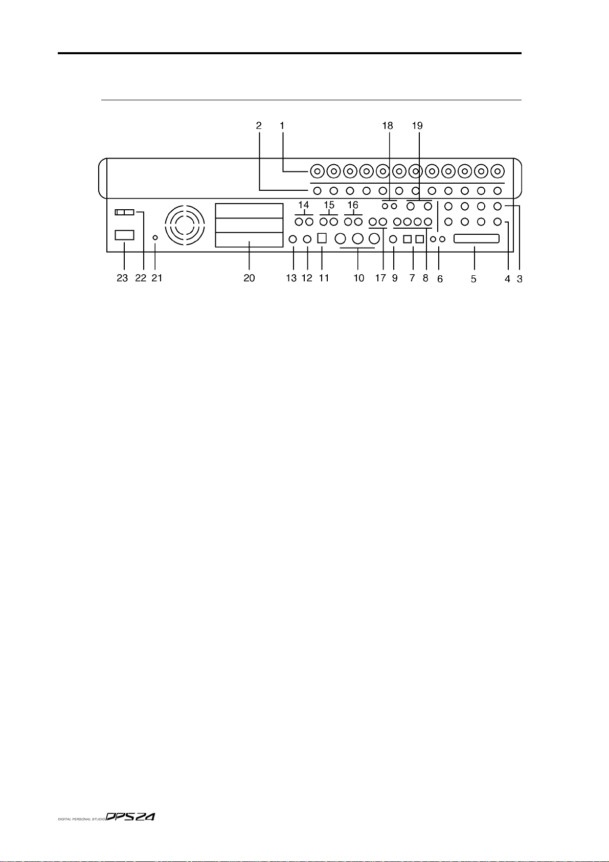
REAR PANEL
REAR PANEL
The rear panel has a comprehensive selection of connectors to interface the DPS24 with a
wide range of analogue and digital equipment. These are:
1. INPUTS - BANK A
Across the top of the rear panel are the two banks of analog inputs. The top r ow (Bank A) are
balanced inputs on XLR/TRS jack combos. These can accommodate XLR connectors or TRS
(tip, return, send - stereo) 1/4" jack plugs.
2. INPUTS - BANK B
The second row of inputs (Bank B) are TRS jacks that can accommodate balanced inputs.
Banks A and B ar e switched fr om the fr ont panel using the switches across the top of the panel
3. CHANNEL INSERT SENDS/DIRECT OUT
4. CHANNEL INSERT RETURNS/ADC INPUTS
Inputs 1-4 also feature balanced insert points allowing you to patch in professional external
processors such as noise gates, compressors, etc.. Although each channel of the DPS24 has a
compressor/gate, you may want to use external valve units or other devices.
The channel insert sends (3) can also be used as balanced direct outputs and the channel
insert returns (4) can also be used to accept external pre-amps or 19" 'channel strips' therefor e
by-passing the internal pre-amps on the DPS24 for these channels.
5. SCSI CONNECTOR OPTION
The optional 68pin Wide-SCSI interface IB-24SCSI may be installed here allowing you to
connect external SCSI drives to the DPS24.
6. DIGITAL I/O
These RCA phono connectors offer SPDIF digital audio input and output. The input is freely
assignable to channels within the DPS24 and the output can accept a wide variety of internal
audio sources (the default is the master stereo L/R output).
7. MULTI-PURPOSE LIGHT PIPE I/O
These optical connectors can be configured to carry either stereo SPDIF or 8-channel ADAT˛
digital input/output.
8. AUXILLIARY SENDS 1-4
AUX SENDS 1-4 default to being output here for use with external effects processors. How-
v1.6 Operator’s Manual
Page 17

REAR PANEL
ever, it is possible to patch other audio sources to appear at these outputs if you wish.
9. WORDCLOCK I/O
When wordclock is selected as the sync source, this BNC is set to receive wordclock. At all
other times, this BNC is set to generate wordclock.
10. MIDI IN/OUT/THRU
The MIDI IN connection can accept MIDI Time Code for synchronising to external equipment such as sequencers.
The MIDI OUT connector can generate MIDI Time Code or MIDI Clock so that sequencers,
etc., may be synchronised to the DPS24. The MIDI OUT can also generate MIDI Controller
events such as volume and pan allowing the DPS24 to control (mix) external equipment (for
example, samples, sound modules, etc.).
The MIDI THRU connection passes MIDI data received at the MIDI Input.
11. USB CONNECTOR
This is provided for connection to a personal computer using the akSys TrackView software
or the akSysServer audio file transfer utility.
12. PS2 KEYBOARD CONNECTOR
You may attach a PS2 keyboard here to assist with naming items in the DPS24.The key mapping of the keyboard to DPS24 functions is shown in the appendix section.
5
13. FOOTSWITCH INPUT
This 1/4" jack socket can accept a footswitch for hands-free recording and playback of the
DPS24. This input can also accept an Alesis LRC˛ remote controller allowing simple remote
control (when overdubbing vocals in a separate studio are or vocal booth, for example).
The key mapping of the LRC to DPS24 functions is shown in the appendix section.
14. MASTER STEREO OUTPUT
These balanced outputs should be connected to the line inputs of your stereo mastering machine.
15. MAIN MONITOR OUTPUT
These balanced outputs should be connected to the line inputs of your main control room
monitor amplifier or powered speakers.
16. NEARFIELD MONITOR OUTPUT
These balanced outputs should be connected to the line inputs of a smaller monitoring system
powering smaller speakers. You may switch between the MAIN and NEARFIELD monitoring
systems using the NEAR switch in the monitoring section of the DPS24's control surface.
17. STUDIO FOLDBACK OUTPUTS
These outputs should be connected to a separate monitoring system (typically an amplified
headphone monitoring system) located in a separate studio recording area , vocal booth, etc..
The audio feed to these outputs is derived via AUX 3/4 allowing an independent mix to be
sent to these outputs when track laying and overdubbing.
NOTE:
is disabled. This is selected in the MIXER / FX/AUX SETUP page.
When either of the STUDIO OUTPUTS are enabled, the respective AUX out put (3 and/or 4)
18. 2-TRACK INPUT
You should connect the outputs of your stereo mastering machine to these RCA phonos. You
can monitor this input using the 2-TRACK switch found in the monitoring section of the
DPS24's control surface. However, the 2-TRACK input can also be freely patched within the
DPS24 and used as a record source if you wish.
v1.6 Operator’s Manual
Page 18

6
REAR PANEL
19. AUX IN
This is a balanced stereo input that can be used for a variety of purposes. It can be used to
bring in an external sub-mixer (for example, to expand the number of input channels for
sound modules, samplers, drum machines, etc., that may be being sequenced during
mixdown) or it can be used as a stereo effects return. By default, this signal feeds the main L/
R bus via the stereo AUX mixer channel prior to the master stereo fader. However, the AUX
IN can also be freely patched within the DPS24 and used as a record source if you wish.
20. EXPANSION SLOTS
These three slots can be used to accept a variety of optional expansion cards, such as:
* IB-24ADT : ADAT˛ Expansion card, adding 16 more channels of ADAT˛ digital input
output and an ADAT˛ SYNC OUT connector to control the transports of ADAT˛ machines
from the DPS24.
* IB-24LTC : SMPTE/EBU Time Code Reader/Generator card for synchronization with
other devices such as Tape machines and Video decks.
* The third expansion slot is reserved for future options.
21. GROUND TERMINAL
Connect this to some earthed metalwork if you experience any mains hum or interference as
it may help reduce it.
22. POWER SWITCH
This is used to switch the DPS24 on and off.
23. POWER CONNECTOR
This should be attached to a suitable cable connected to a mains power source.
v1.6 Operator’s Manual
Page 19
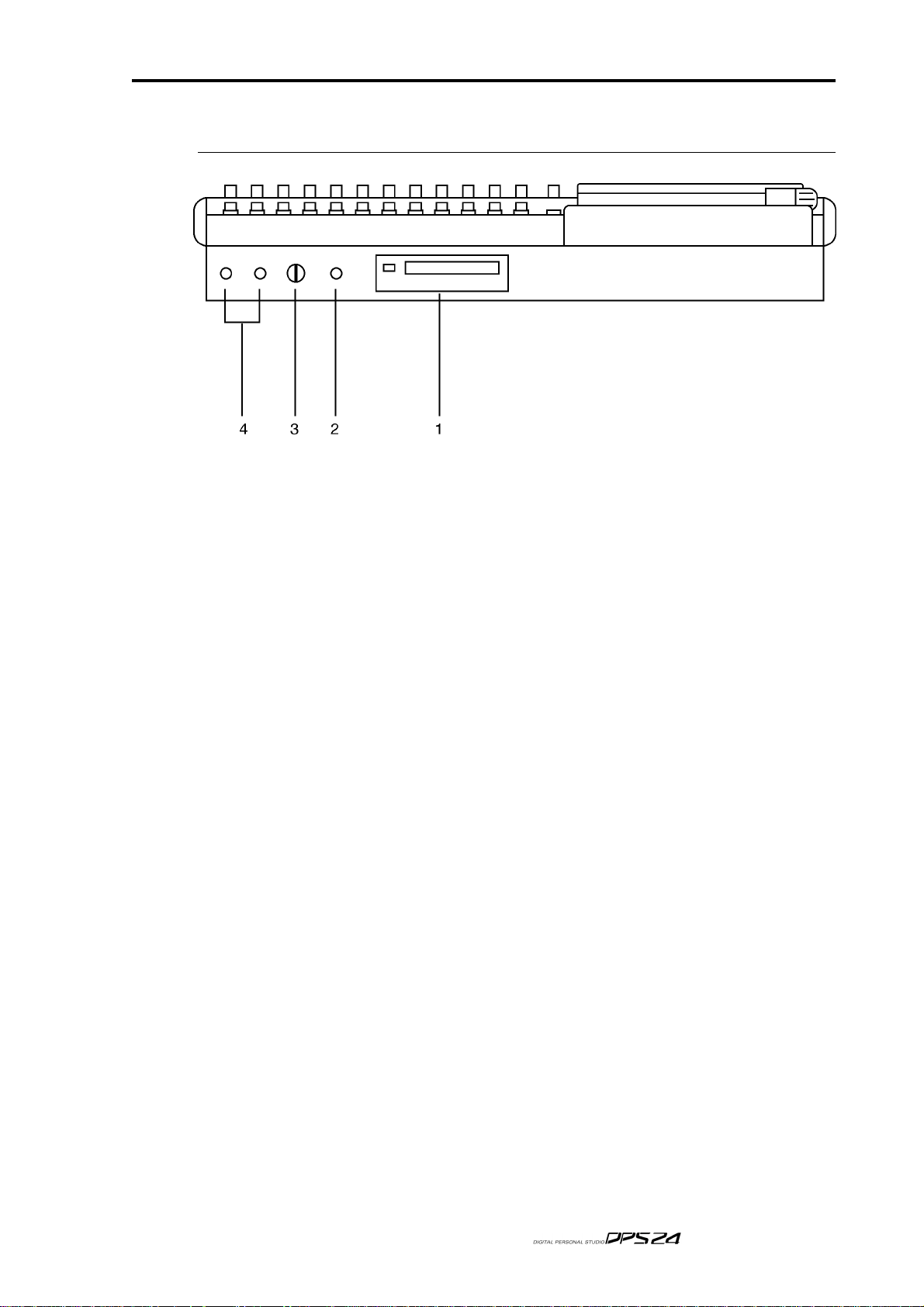
FRONT PANEL
1. CD-RW/CD-R DRIVE BAY
An IDE CD-RW is installed here.
It is also possible to install a removable IDE hard drive bay.
FRONT PANEL
7
2. HI-Z GUITAR INPUT
An electric guitar (or bass guitar) may be DI'd into this high impedance input.
Note that when a jack is plugged into this input, it uses Input Channel 12, and Inputs 12A
and 12B on the rear panel are overridden and cannot be used.
3. HEADPHONE LEVEL
This allows control of the level of the signal appearing at the headphone outputs.
4. HEADPHONE OUTPUT
Two headphone output connectors are provided. Both are identical (i.e. wired in parallel)
and carry a duplicate of the MONITOR output.
v1.6 Operator’s Manual
Page 20

8
Top Panel
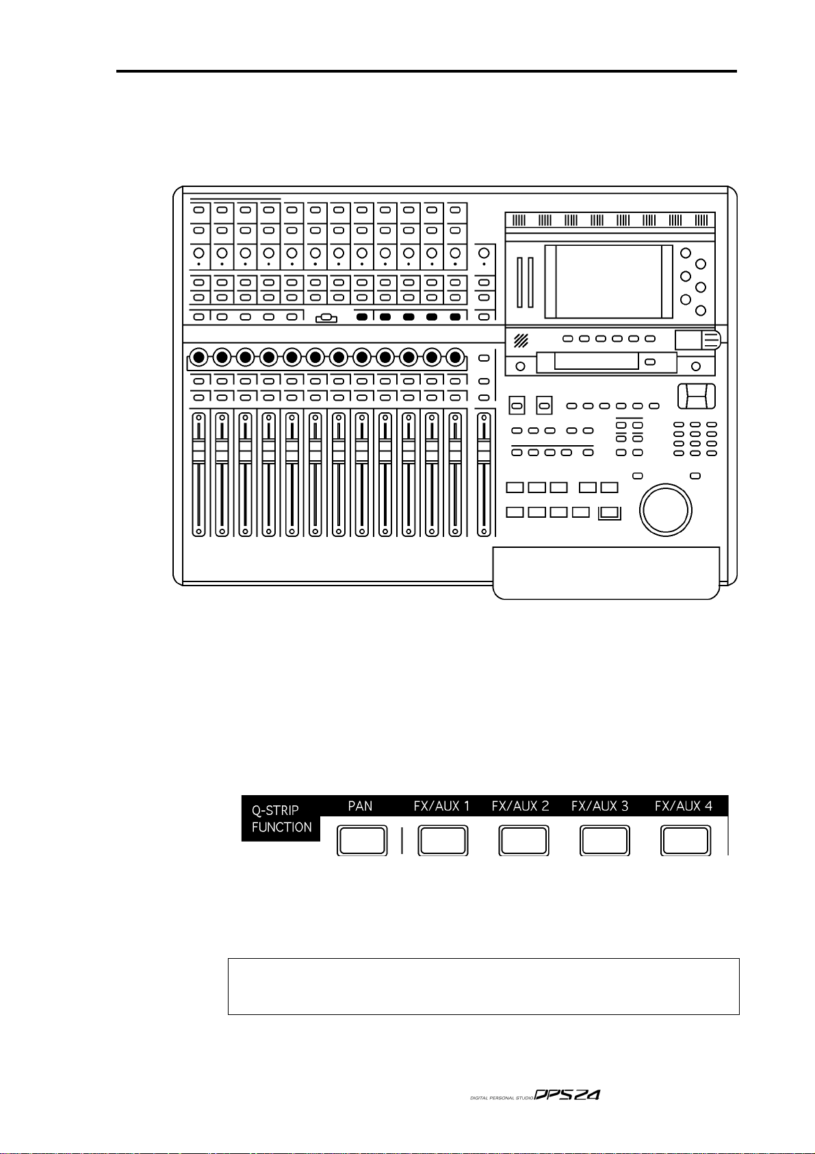
TOP PANEL
GETTING AROUND THE DPS24
This section deals with the DPS24's control surface. Although we would like to think that
most of it should be fairly self-explanatory, please read this section to gain a full understanding of the DPS24's functions.
The panel is laid out logically with many dedicated keys that provide direct access to the
most commonly used functions employed when recording, track laying, overdubbing and
mixing and the DPS24's control surface is designed in such a way that for every day use, it
should not be necessary to access obscure, LCD-driven menus - with its 'knobby' front panel,
operation is designed to be as 'hands-on' and 'traditional' as possible. For example....
For track laying, route the inputs to the appropriate track(s) using the Group function as on
a traditional mixer, arm the track(s) for record and press PLAY and RECORD together. Drop
out of record by pressing PLAY again. To overdub, rewind, re-group, select different tracks
for record and repeat the process, monitoring previously recorded material via the DISK
TRACKS fader bank.
Want to pan your tracks? Simply use the row of encoders above the faders. Want to add
effects? Select the appropriate FX send in the Q-STRIP FUNCTION panel and adjust the
encoders to set FX send levels as necessary.
Need to tweak EQ? Select the appropriate channel(s) using the channel SELECT keys, press
the Q-CHANNEL key and adjust the EQ using the Q-CHANNEL encoders.
Need to tweak an effect? Press FX and use the Q-LINK controls to modify parameters (and
with the Q-CHANNEL selected, you can adjust the channel parameters AND the effects parameters simultaneously).
If you are working with artists in separate rooms, set up a 'foldback' cue mix using pre-fade
AUX 3 and/or 4 and the STUDIO outputs - even speak to them via the DPS24's internal
talkback mic during the track laying process.
Having laid down some tracks, you hear something that needs deleting! Simply hit EDIT,
select the appropriate track(s), mark the offending region with the IN/OUT keys and press
CUT or ERASE. Similarly, you want to use that one great guitar riff elsewhere in the project
- select the appropriate track(s), press EDIT, mark the region, copy it and paste it wherever
it's needed.
You get the picture!
And so far, unlike other digital mixers/recorders, all of this is achieved without hardly ever
having to refer to the LCD!
To find out more, read on.
ILLUMINATED KEYS
Illuminated keys will light when selected as you would expect.
However, in certain circumstances, these keys flash to indicate that they are in a different
status. For instance, the CH ON keys are lit when mixer channels are ON (not muted), but
they flash when the mixer channels are solo'ed.
Also, the RECORD/EDIT SELECT keys for the 24 tracks use bi-color LEDs, red for Record
(flashing when ready, lit when recording) and green for Edit,
v1.6 Operator’s Manual
Page 21
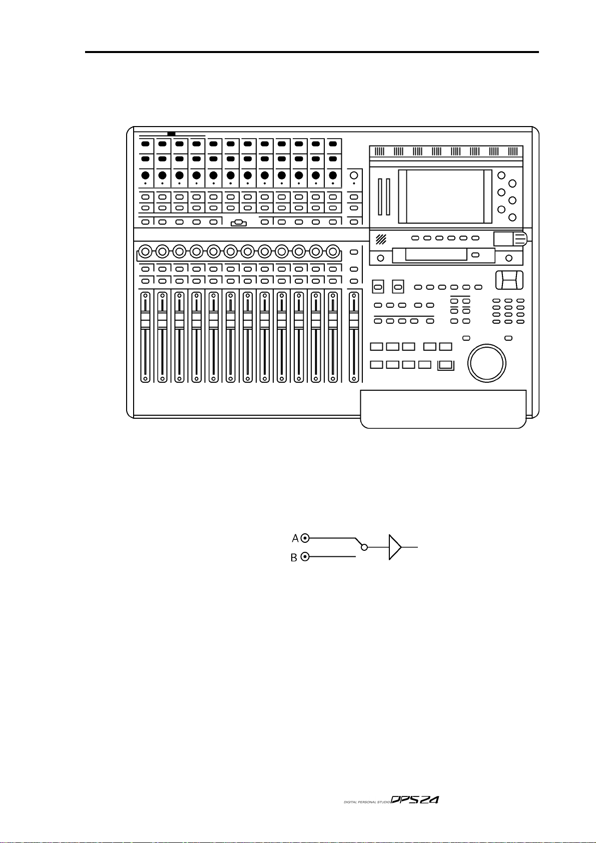
INPUTS
Across the top of the panel are controls associated with the twelve analog input preamps.
INPUTS
9
The functions are:
48V ON/OFF Switches on 48 volt phantom power to Inputs A 1-4 allowing these chan-
nels to be used with condenser mics.
A/B The switches running along the top switch between Input A or B.
(A is the XLR combo, B is the 1/4" jack)
LINE/MIC The next row of switches set the input (TRIM) sensitivity between line (-
15dB <> +45dB) and mic (0dB <> +60dB).
TRIM This pot allows you set the input channel's initial gain according to the
setting of the LINE/MIC switch.
SIG/CLIP This tri-coloured LED shows the level of the input signal after the input
pre-amp. It illuminates as follows:
-60dB or less OFF
-60dB -> -3dB GREEN
-3dB YELLOW
0dB RED (clip)
v1.6 Operator’s Manual
Page 22
10
Top Panel
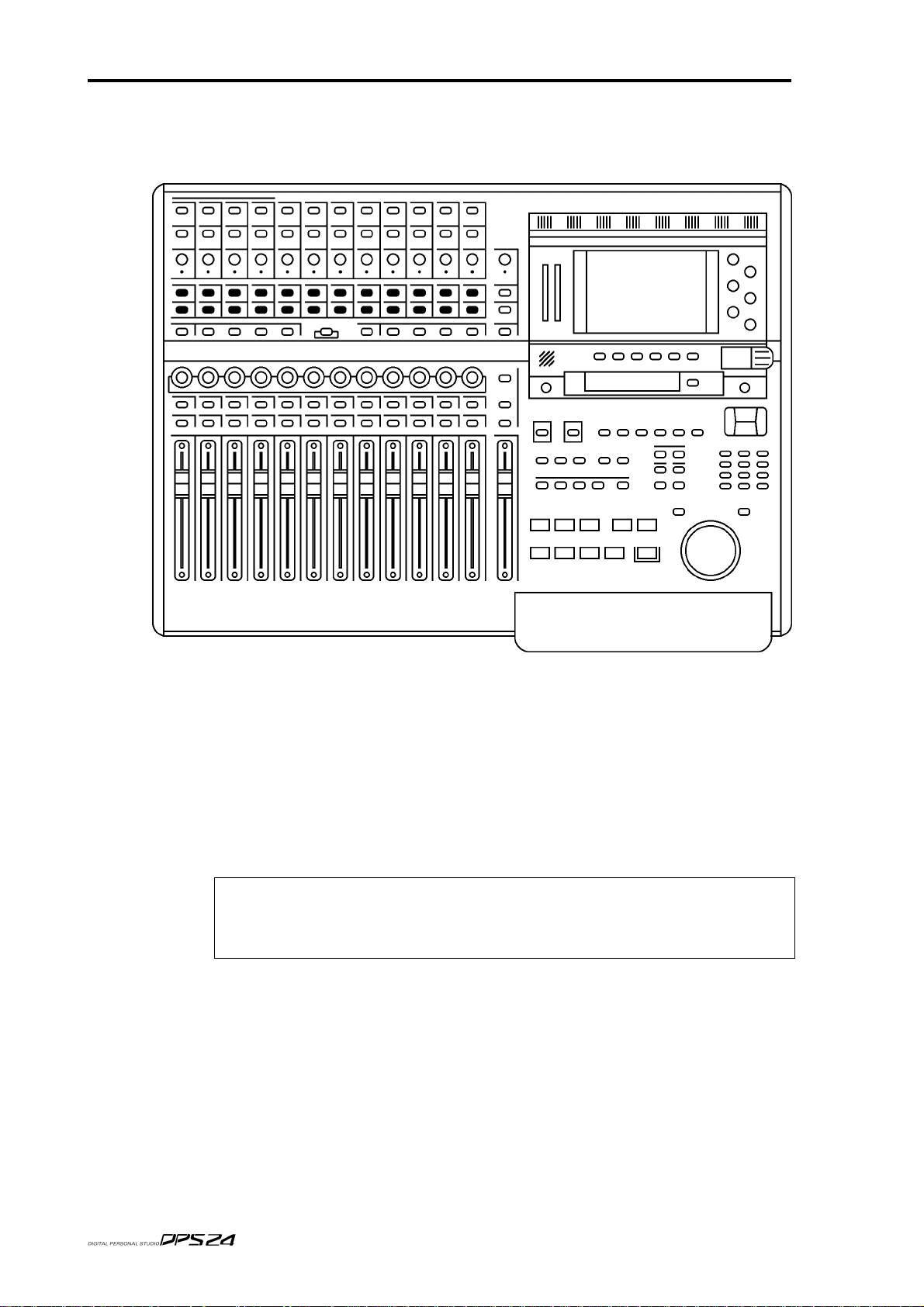
RECORD/EDIT SELECT KEYS
Below the inputs are the RECORD/EDIT SELECT keys for Tracks1-24:
These keys have bi-coloured LEDs and normally, when recording, they illuminate red and
are used to select tracks for record. However, when the EDIT mode is enabled, these keys
illuminategreen and are used to select tracks for editing.
The number shown to the right of each key shows the default Group assignment. As on a
'traditional' console/recorder combination, the group outputs are patched to the disk tracks
and channels are routed to them by way of the Groups (Groups 1-8 routed to Tracks 1-8, 9-16
and 17-24). So, for example, to route Input 5 to Track 3, you would assign it to GROUP 3/4.
To route, say, Tracks 1, 2, 3 and 4 to, say, Tracks 13 and 14 for a stereo bounce-down, you
would assign them all to GROUP 5/6.
NOTE:
group routing arrangement so the default assignment shown alongside the record track numbers may
not be applicable if you have changed them. Routing and patching is explained in more detail later in
this manual.
Because of the flexible patching facilities in the DPS24, it is possible to override the default
v1.6 Operator’s Manual
Page 23
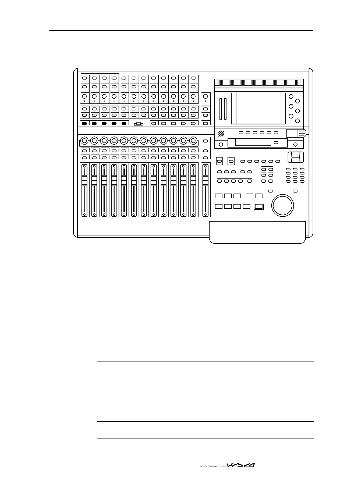
L/R AND GROUP ASSIGN KEYS
Below the RECORD/EDIT SELECT keys to the left of the panel are the ASSIGN keys:
L/R AND GROUP ASSIGN KEYS
11
These allow you to route signals to the groups and also to the stereo L/R bus.
To route any channel to a Group (and hence to the track(s)), press the desired GROUP key.
The current GROUP key will flash. The SELECT keys for any channels assigned to that group
will illuminate whilst those that aren't assigned will flash. Press the channel SELECT keys
for the channels you wish to assign (or press an illuminated key to de-assign a channel).
When done, press the GROUP key again to return to normal mode. The GROUP key will
stop flashing.
NOTE 1:
cannot be routed to that bus. This applies to GROUP, AUX and MIDI mixer channels.
NOTE 2:
groups to groups. Groups can be assigned to the stereo L/R bus, however.
NOTE 3:
not be flashing.
To assign a channel to the L/R output bus, press the L/R key. The L/R key will flash.The
SELECT keys for any channels assigned to the L/R bus will illuminate (and those that aren't
will flash).
Press the channel SELECT keys for the channels you wish to assign (or press an illuminated
key to de-assign a channel).
When done, press the L/R key again to return to normal mode. The L/R key will stop flashing.
If a channel SELECT key is not lit nor flashing, it means that the channel in question
Almost any channel can be assigned to any group. However, it is not possible to assign
In normal operation, i.e. when not assigning channels to groups, the GROUP keys should
NOTE:
should not be flashing.
In normal operation, i.e. when not assigning channels to the L/R bus, the L/R key
v1.6 Operator’s Manual
Page 24

12
Top Panel
SUB-GROUPING CHANNELS TO THE L/R MIX
Very often (especially during mixdown), it is very useful to be able to sub-group certain
channels to the stereo L/R bus via the Groups. For example, all your drums and percussion
channels could be sub-grouped to one group, all your keyboard parts to another, all your
backing vocals to another, etc., so that you have control over these elements with a single
Group fader.
Routing groups to the stereo L/R bus is done simply by pressing the L/R key and, in the
GROUPS/FX fader bank, pressing the group channels' (1-8) SELECT key(s) as appropriate.
This is consistent with assigning other channels to groups.
NOTE:
them appearing twice. - once through the direct connection of the channel to the stereo L/R bus and
secondly through its connection to the stereo L/R bus via the subgroup.
Channels which are routed to a sub-group need to be taken out of the stereo L/R bus to avoid
v1.6 Operator’s Manual
Page 25
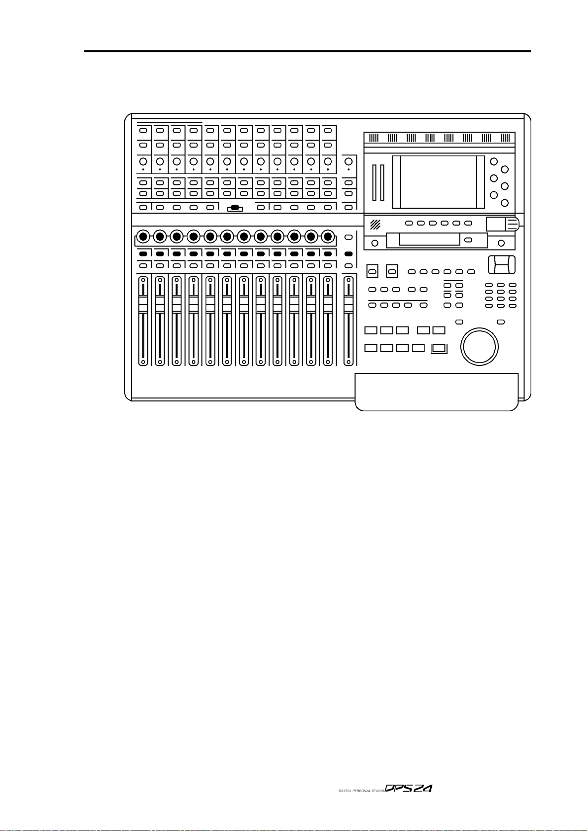
Q-STRIP FUNCTION KEYS/CHANNEL ENCODERS
Q-STRIP FUNCTION KEYS/CHANNEL ENCODERS
Below the RECORD/EDIT SELECT keys to the left of the panel are the Q-CHANNEL key
and the Q-STRIP FUNCTION keys:
13
Directly above the channel faders is a row of continuous rotary encoders (the Q-STRIP / QCHANNEL) with a 'collar' of LEDs around each of them that serve a variety of purposes.
When the Q-CHANNEL key is off, they operate as the Q-STRIP.
On power up, their default function is to act as P AN contr ols with one pan contr ol for each of
the channels of the current Fader Bank.
However, they may be used to set FX/AUX send levels.
This functionality is selected using the Q-STRIP FUNCTION keys:
PAN : Sets the rotary encoders to act as pan controls for each of the channels.
FX/AUX 1-4 : Sets the rotary encoders to act as send levels for the internal effects channels
or to the AUXILIARY bus.
NOTE:
position. The same is true for FX/AUX3/4 - if set to stereo, FX/AUX3 sets the level and FX/AUX4
sets panning.
If the sends are configured as stereo sends, FX/AUX1 sets the send level and FX2 sets the pan
v1.6 Operator’s Manual
Page 26

14
Top Panel
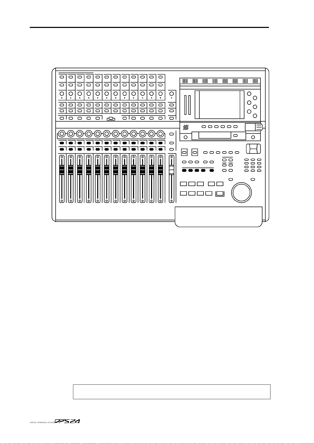
FADER FLIP
It is also possible to 'flip' (or swap) the faders and FX/Aux sends allowing you to set FX/
Aux sends using the motorized faders. This is useful when you require very abrupt changes
to FX/Aux sends... to allow for precision when setting the FX/Aux send levels, the encoders
need a few turns to cover the entire range. The faders, on the other hand, can cover the entire
range in one swift movement.
To flip the faders, simply 'double-click' the FX/Aux buttons:
Press the FX/Aux key once to select it. Press it again to 'flip'.
When 'flipped, the faders set FX/Aux send level and the encoders now set channel level.
When 'flipped', the LED in the key will flash to indicate its status.
Press it again to return to normal operation.
NOTE:
Aux1/2 send level and the encoders set the channel level.
However, when FX/AUX2 is 'flipped', the faders set FX/Aux1/2 send level and the encoders set FX/
AUX1/2 send pan position. The same is true for FX/AUX3/4.
If the sends are configured as stereo sends, when FX/AUX1 is 'flipped', the faders set FX/
v1.6 Operator’s Manual
Page 27
Q-CHANNEL SELECT / Q-CHANNEL ENCODERS
Q-CHANNEL SELECT/Q-CHANNEL ENCODERS
In the centre of the panel is the Q-CHANNEL key:
15
One of the most useful features of the DPS24 is that the row of encoders directly above the
faders can be switched to become a complete channel's worth of parameters allowing you to
have 'hands-on' control of panning, EQ and FX/Aux sends. This 'mode' is enabled by press-
ing the Q-CHANNEL switch located centrally on the upper panel.
When the Q-CHANNEL key is on (illuminated), the encoders function as a complete channel
strip for the selected Channel as follows from left to right (as labelled underneath the
encoders):
PAN
LOW SHELF EQ FREQUENCY
LF GAIN
SWEEP EQ FREQUENCY
SWEEP EQ GAIN
SWEEP EQ 'Q'
HIGH SHELF EQ FREQUENCY1
HF GAIN
FX/AUX 1 SEND LEVEL
FX/AUX 2 SEND LEVEL
FX/AUX 3 SEND LEVEL
FX/AUX 4 SEND LEVEL
v1.6 Operator’s Manual
Page 28

16
Top Panel
Furthermore, the function of the Q-STRIP FUNCTION keys described earlier also change
when the Q-CHANNEL is enabled:
The labelling underneath the keys denotes their function when in Q-CHANNEL 'mode' and
you have 'hands-on' control to bypass the EQ and to switch FX/AUX 1-4 as pre- or post-fade.
Of course, for the Q-CHANNEL 'mode' to be applicable, you must select a channel for editing (i.e. you should press a channel's SELECT key just under the row of encoders). The SELECT key of the selected Channel is illuminated. On power up, the default selection is the
Master Channel.
NOTE:
Channel on the LCD. Then , when disabling Q-CHANNEL, the display returns to the previous screen.
Enabling Q-CHANNEL automatically calls up the MIXER / CHANNEL page of the selected
v1.6 Operator’s Manual
Page 29
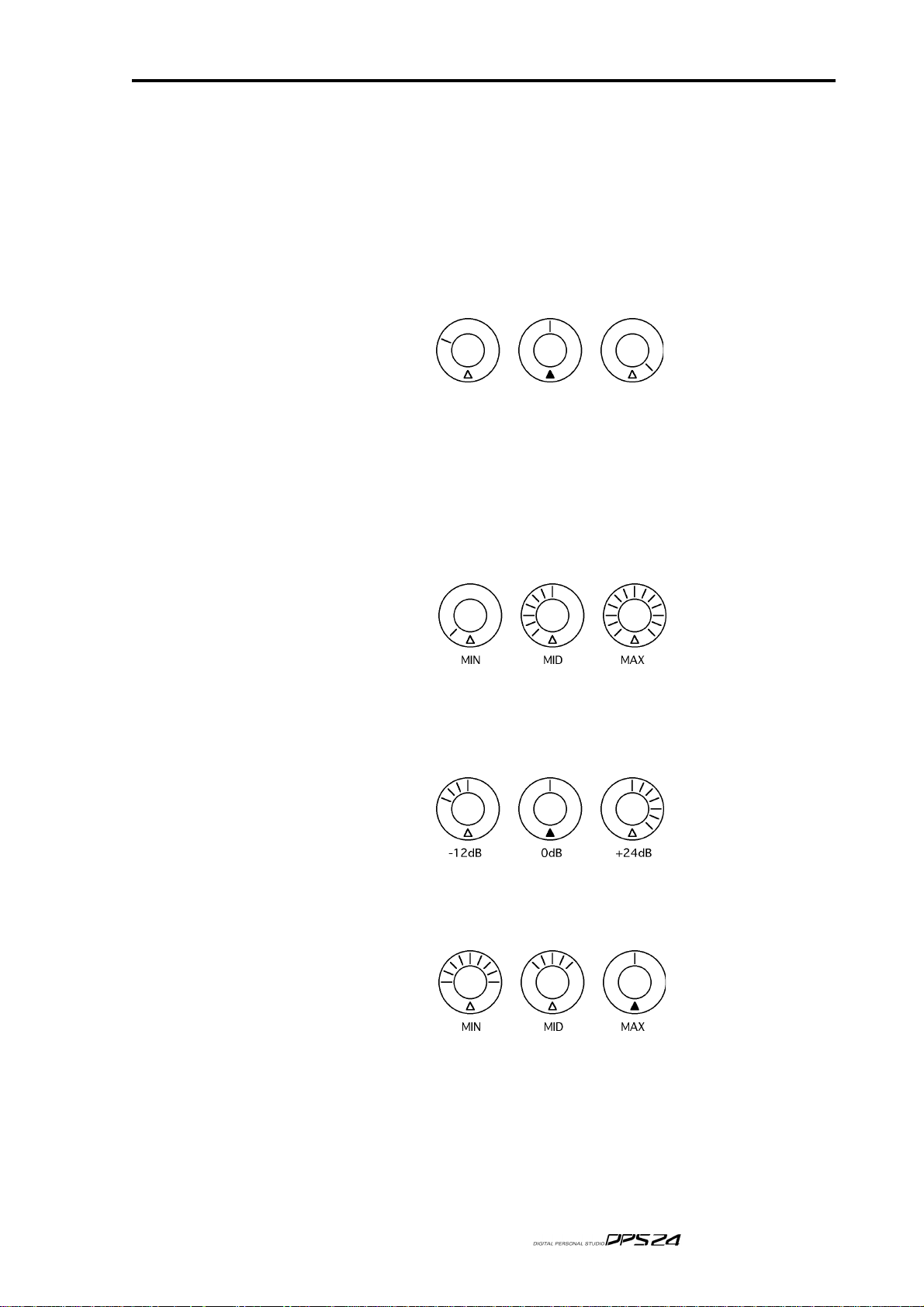
Q-STRIP / Q-CHANNEL ENCODERS
Q-STRIP/Q-CHANNEL ENCODERS
Around the encoders is a collar of LEDs that show the encoder's value. As the control is
moved, so do these LEDs illuminate to show its position. However, the way these LEDs
illuminate depend on the control's function.
PAN POSITION / EQ FREQUENCY
When used as a pan pot, the LEDs around the encoders illuminate as follows:
When the encoder is set to MID, the red LED at the bottom illuminates as well. This is to
assist with viewing the encoder(s) at an angle where the top middle LED may not be visible.
LEVEL CONTROL
When the encoders are used as level controls (e.g. FX/AUX SEND), the LEDs illuminate as
follows:
17
EQ GAIN
When the encoders are being used to set EQ gain in the Q-CHANNEL, the LEDs illuminate
as follows:
EQ 'Q'
When the encoder is used to set EQ 'Q' in the Q-CHANNEL, its' LEDs illuminate as follows:
In this way, the control gives an almost graphic indication of the 'width' of the sweep EQ.
With the control at minimum, the Q is at its widest; at maximum, the Q is at its narrowest.
v1.6 Operator’s Manual
Page 30
18
Top Panel
FADERS/FADER BANKS
Below the DPS24's Q-STRIP/Q-CHANNEL encoders are the channel faders and SELECT
and ON/SOLO keys:
Each channel is identical whether it's an input or a disk channel (the GROUP/FX channels
are different and those differences are described on the next page). Each channel has a long
throw 100mm motorised fader which is touch sensitive for use with the mixer's automation
and simply touching the fader will make it active.
Channels may be muted using the green ON key above the fader.
When the channel is ON, the key illuminates; when it is OFF (muted), the key is not lit.
By pressing SHIFT+ON, the channel can be solo'd.
When a channel is solo'd, the ON key's LED flashes (and a large SOLO LED flashes in the
MASTER section). SOLO operation is described later in the manual.
A channel can be selected for tweaking using the channel SELECT key above each fader.
The SELECT keys are also used in conjunction with the ASSIGN keys to r oute channels to the
L/R bus and/or to Groups (and hence to disk tracks) for recording.
The SELECT keys can be used to link adjacent odd/even Channels as a stereo pair.
To link a pair of channels, press the SELECT key of one of the channels while holding down
the SELECT key of the adjacent channel. To un-link them, use the same procedure.
Once linked, pressing the SELECT key for either channel will select both, and the ON key of
either channel will be used for muting/solo'ing both channels.
NOTE:
channels 1&2 or 3&4, but not channels 2&3.
Only odd/even adjacent channels can be paired., not even/odd channels, i.e. you can link
v1.6 Operator’s Manual
Page 31

FADERS / FADER BANKS
The different channels are selected using the FADER BANK keys located above the trans-
port keys. The types of mixer channel types are as follows:
INPUTS 12 general purpose mixer channels which can be used to mix the
DPS24's various input sources. The channels can also be used to add
EQ and dynamics and also to send the channels to either the internal
effects and/or the AUX bus. By default, input sour ces ar e ADCs 1-12.
TRACKS 24 mixer channels which are sourced from the internal disk recorder.
The channels can also be used to add EQ and dynamics and also to
send the channels to either the internal effects and/or the AUX bus.
19
GROUP
FX RETURN
FX SEND 4 channels providing control of the 4 fx bus master send levels.
AUX SEND 4 channels providing control of the 4 aux bus master send levels.
AUX IN A stereo auxiliary mixer channel allowing the AUX L/R inputs to be
MIDI CONTROLLER 16 channels each providing 2 MIDI controllers which can be assigned
There are 4 fixed Fader Banks and 5 assignable User Banks arranged as follows :
INP 1-12 These channels control Inputs1-12.
TRACKS 1-12 These channels control Tracks 1-12.
TRACKS 13-24 These channels control Tracks 13-24.
GROUP/FX Channels 1-8 control the Group Output levels, and Channels 9-12
USER BANK Selects the first bank of user assignable channels. By default, they are
8 channels providing control of the 8 group bus master levels. Pan, EQ,
dynamics and FX/AUX sends are not available on these channels.
By default, these 4 stereo channels provide control the stereo returns of
the internal effects with balance control and FX/Aux sends. However,
these channels can be re-patched to mix any of the DPS24 input sources.
mixed to the main L/R bus with level and mute control only. This
channel has a fixed source.
to any MIDI channel or controller. Controller #1 is contr olled by the
channel fader and Controller #2 is controlled by the channel's PAN
control. By default, these are configured to send MIDI Volume (CC#7)
on Controller #1 and MIDI Pan (CC#10) on Contr oller #2.
control the stereo FX return channels (default to internal FX returns)
assigned as follows:
- Channels 1-4 control the master send levels to the FX buss.
- Channels 5-8 control the master send levels to the AUX buss.
- Channel 9 controls the stereo AUX IN.
- Channels 10-12 control MIDI controllers1-3
SHIFT + INP 1-12 Ext User-Bank 1 (no default assignment)
SHIFT + TRACKS 1-12 Ext User-Bank 2 (no default assignment)
SHIFT + TRACKS 13-24 Ext User-Bank 3 (no default assignment)
SHIFT + GROUP/FX Ext User-Bank 4 (no default assignment)
The User Banks configurations are assigned in the SETUP mode.
v1.6 Operator’s Manual
Page 32

20
Top Panel
MASTER SECTION
To the right of the channel faders is the MASTER fader:
The MASTER section also has a long throw, touch sensitive, motorised fader. This controls
the L/R bus which, by default, appears at the STEREO OUT.
NOTE:
the L/R bus to the STEREO output. If another audio source is patched to the STEREO output, the
MASTER fader will not affect that audio source's level.
Above the fader is a TALKBACK switch. This routes the internal talkback mic to the STUDIO
outputs so that the engineer in the control room can talk to the 'talent' in a separate studio area.
The key is a 'press-to-make' switch that needs to be held down for the talkback mic to be
routed to the STUDIO outputs.
NOTE:
L/R outputs. This is set in the MIXER - FX/AUX SETUP page.
The illuminated SELECT key allows you to select the master channel for editing.
The illuminated STUDIO > CR key allows you to route the mix created on AUX 3 and 4 as the
STUDIO cue mix to the monitor output feeding the control room's monitoring system. In this
way, it is possible for the control room engineer to set the mix up very conveniently on the
control room's speakers.
The TALKBACK and STUDIO outputs are explained later in this Reference manual.
Due to the DPS24's flexible patching system, it is possible to route audio sources other than
To facilitate this, the AUX 3/4 sends need to be configured to be sent to the STUDIO
v1.6 Operator’s Manual
Page 33

MONITOR SECTION
Directly above the MASTER section is the MONITOR section:
The functions are (from top to bottom):
MONITOR SECTION
21
MONITOR LEVEL Sets the level of the signal appearing at the MAIN or NEARFIELD
monitor outputs.
!!! SOLO !!! This LED flashes whenever a channel is solo'd.
Although the channel's ON key flashes when it is solo'd making it
perfectly obvious which channel is being solo'd, it is possible that a
different FADER BANK may be selected and so the solo'd channel
may not be visible (for example, Input 5 may be solo'd but the current
FADER BANK might be, say, Tracks 1-12). As a result, it may not be
clear that a channel is solo'd. This 'master' SOLO LED helps overcome this by showing that a channel somewhere is solo'd.
2-TRACK This switches the 2-TRACK input into the main monitor output, over-
riding the main L/R mix. Normally, this will be used to check the
output of an external stereo recorder/player . However, the 2-TRACK
switch exists only on the monitor output and it does not affect the
master stereo L/R output.
By default, the stereo 2-TRACK input is the source for this, but it is
also possible to route the stereo AUX IN or the stereo DIGITAL IN
instead in the SETUP mode.
v1.6 Operator’s Manual
Page 34

22
Top Panel
MONO This switches the monitor output to mono. Switching to mono does
not affect the STEREO L/R outputs, only the monitor outputs (MAIN
and NEARFIELD). Thus it is possible to check a mix in mono on the
control room speakers without affecting the STEREO L/R mix to the
master recorder. Similarly, when monitoring the 2-TRACK input (either after or during mixdown), it is possible to switch to mono for
reference checking.
NEAR This switches the monitor output from the MAIN outputs to the
NEARFIELD connections on the rear panel.
Typically, the MAIN outputs of the DPS24 will be connected to a high
quality, high power amp/speaker monitoring system whilst the
NEARFIELD outputs will be connected to a smaller system, perhaps
even a domestic hi-fi amp powering smaller speakers. Thus, with
NEAR switched OFF, monitoring will be via the MAIN monitor outputs but with NEAR switched ON, monitoring will be via the smaller
amp/speakers. In this way, you can switch between monitoring systems quickly and conveniently from the DPS24's panel.
v1.6 Operator’s Manual
Page 35

LCD 'POD'
Top right of the meters.
To the right of the LCD are six Q-Link pots, Q1-Q6, used to set parameters on the LCD.
LCD “POD”
23
Below the screen are six 'soft' keys, F1-F6, the functions of which change according to the
screen being displayed.
To the left of the function keys is a simple talkback mic. Its level can be regulated using the
TB LEVEL pot directly below it.
Underneath the function keys is a dedicated timecode display. This can be switched between
timecode (hours : minutes : seconds : frames) and BBC (Bars : Beats : Clocks) using the DIS-
PLAY SELECT key to its right, Display status is indicated by two small LEDs between the
display and the DISPLAY SELECT key.
Finally, the CONTRAST control allows you to adjust contrast for the best view according to
your viewing angle.
v1.6 Operator’s Manual
Page 36

24
Top Panel
LCD LAYOUT
The layout of the LCD is divided in various sections or blocks.
A typical LCD screen of the DPS24 would look like this:
SOFT KEYS
In all pages, at the bottom of the screen, the functions the softkeys F1-F6 are shown.
There are a few types of soft keys along the bottom of the LCD:
This is typical 'do it' style key.
This is a typical 'go-to-another-page' key.
Some soft keys are also uses as ON/OFF switches:
or Indicates that a function is on.
or Indicates that a function is on.
Double width equivalents also exist:
PROJECT INFO BAR
In all pages, at the top of the screen, the project drive and the currently active project are shown
along with the currently selected mix scene and the amount of fr ee mono recording time on disk.
v1.6 Operator’s Manual
Page 37

SAVE INDICA TOR
Whenever something is changed in a project, it is autosaved.
When this happens, a small "warning" icon appears in the FREE box at the top right of the
display:
SAVE INDICATOR
25
IMPORTANT NOTE:
Doing so might result in lost data and maybe irreparable damage to your disk drive.
After making any changes to your project, always wait until the icon shown above clears
before switching off.
If you turn off the power while saving project data onto hard drive, the project data may be
damaged.
As a safety, the DPS24 automatically creates a hidden backup project (a copy of the current
project) while saving project data .
In case the original project data gets corrupted, the DPS24 will boot up with the back up
project instead.
When the DPS24 boots up with the backup project, something similar to the following message will be displayed as a reminder:
When this icon appears, it is essential that you do not switch the DPS24 off.
However, please keep in mind that it is still possible to damage project data if you power-off
the DPS24 while writing to the disk.
The DPS24 is writing to the disk after any recording, editing or mixing operation (as simple
as touching a fader), or after changing any setting.
It usually takes only 10-20 seconds to complete a write operation of the last changes.
Please wait until the icon disappears to power-down the unit.
If the last used Project gets corrupted and the DPS24 is not able to recover the damaged However,
you can bypass auto-loading the last project on power-up by using the following procedure:
* power-off
* turn the shuttle wheel (outer ring) counterclockwise to 11 o'clock (the little notch pointing
towards the IN key)
*
power-up while holding the shuttle wheel in this position until the DPS24 finishes booting up.
This will not load the last Project, but create a dummy empty project instead.
From there, you should be able to load other Projects.
You should also be able to recover the audio from the corrupted project using the Audio
Recovery feature described later in this manual.
v1.6 Operator’s Manual
Page 38

26
Top Panel
PROJECT OVERVIEW
In the MAIN SCREEN, and also in the main page of EDIT/DSP modes, a Project Overview is
displayed in the lower portion of the screen:
This shows a graphic representation of the 24 tracks of the project, scrolling from right to left
accross the NOW Time line during playback.
The IN-OUT region is displayed inverted.
On top of the Project OverView, a System Info bar is displayed in the middle of the screen
This provides a reminder of the current Sample Rate, Bit Depth and Frame Rate settings.
WAVEFORM GENERATION INDICATOR
When new audio files are created, either during recording, or while using the DSP features,
the DPS24 calculates each audio file's waveform for display (if the WAVE GEN function is
enabled in SETUP/PREFS, as described later in this manual). This operation is performed by
the DPS24 in the background.
In the MAIN SCREEN, and also in the main page of EDIT/DSP modes, a Waveform Generation indicator icon is displayed in the System Info bar in the center of the screen shows the
status of this background process.
The various displays are:
METER BRIDGE
In the MAIN SCREEN, and also in the main MIXER page, a Meter Bridge is displayed in the
upper portion of the screen, showing small LCD meters for all the channels of the entire Mixer:
The black squares show clipping and you can also see the peak hold indicators:
Waveform generation is off
This animation shows that waveform generation in progress
Waveform generation complete
Waveform generation is inhibited
v1.6 Operator’s Manual
Page 39

Q-LINK CONTROLS
In some pages, on the right side of the screen, adjustable parameters are available. Those
parameters are adjusted using the corresponding Q1-Q6 Q-Link knobs directly to the right
of the screen.
Those Q-link knobs can be used to:
* enter parameter values.
For instance, in the FX or CHANNEL Dynamics pages
or
Q-LINK CONTROLS
:
27
* select option parameters.
For instance in the SETUP pages:
* scroll through lists / data entry
In particular, Q5 and Q6 knobs are often used for scrolling/data entry in as many pages as
possible.
In general, if Q5/Q6 are not used for page specific Q-Controls, Q5 moves left-right and Q6
moves up-down, unless one direction is meaningless, in which case the Q-Link knob for that
direction becomes data increment/decrement.
Following are some examples:
v1.6 Operator’s Manual
Page 40

28
Top Panel
MO VING AROUND THE LCD
Most pages provide immediate access to parameters via the Q-LINK controls on the right.
An example of this would be the FX pages:
Here, you simply select the FX channel and the FX type with the cursor keys and set the
parameters directly with the Q-LINK controls. Most of the DPS24's pages are like this and
have no parameters to set via tedious cursor movement. There are a few pages, however,
which have multiple parameters to select. One example is the CHANNEL page:
In a page such as this, you use the CURSOR keys to move around from parameter field to
parameter field. You can also use Q5 as a quick cursor.
v1.6 Operator’s Manual
Page 41

MOVING AROUND THE LCD
To edit the value you can.....
• Enter a number directly using the numeric keypad, followed by ENTER
• Use the numeric keypad's +/- keys to nudge values
• Use the Q6 as a typical DATA ENTRY encoder
In this example, however, you would probably prefer to use the Q-CHANNEL function to
set the functions shown.
Some pages, however, have quite a lot of fields and unfortunately, there is no option but to
cursor around them with the cursor keys or Q5, and use the numeric keypad's DATA +/
keys or Q6 to set values. An example of this would be the PATCH pages:
29
-
However , ther e are not that many pages like this and also, these are the kind of pages which,
once set, do not require constant usage after that. For the most part, parameters are set using
dedicated controls in the form of either the Q-LINK controls, the Q-STRIP/CHANNEL en
coders of dedicated control surface switches.
-
v1.6 Operator’s Manual
Page 42

30
Top Panel
NAMING
It is possible to name things on the DPS24 from the front panel.
However , we thor oughly r ecommend that you connect a PS2 keyboar d as this makes naming
MUCH easier and suitable keyboards for the purpose can be bought very cheaply at any
high street store that sells computers. Do not use a keyboard that requires a driver installation. Use only a keyboard that does not have special features such as Internet keys, Multimedia keys, built-in trackball. The simpler, the better. For instance, the BTC˛ 5106 costs only a
few US dollars and works well with the DPS24.
When you go to name something, you will see this pop-up:
You can use Q1 to set upper case characters A-Z
You can use Q2 to set lower case characters a-z
You can use Q3 (or the numeric keypad) to enter numbers 0-9
You can use Q4 to enter the following special characters ! # $ % & ' ( ) + , - ; = @ [ ]
You can use Q6 or the cursor keys to move the cursor left/right
You can use F3 to insert spaces
You can use F4 to backspace/delete
Press F6 or the ENTER key to confirm the new name and execute the current function.
Press F1 or the CANCEL key to abort name entry and return to the previous screen.
Whilst is perfectly feasible to enter names in this way, we are the first to admit that it is
nowhere
near as convenient as using an external keyboard.
v1.6 Operator’s Manual
Page 43

PROMPTS
The DPS24 uses prompts to guide you through certain function of the user interface.
For example:
PROMPTS
31
The DPS24 also uses progress displays for functions that take time.
For example:
v1.6 Operator’s Manual
Page 44

32
MAIN CONTROL SECTION
MAIN CONTROL SECTION
Here, you find the following functions:
EXT SYNC This allows you to synchonize the DPS24 with external devices.
When the key is pressed (and the LED illuminated), it enables the Time
Sync synchronization setting (Master or Slave, MIDI or SMPTE).
If Time Sync is set to MTC Slave or SMPTE Slave, the DPS24 will not
play and/or record unless it is receiving external timecode.
If Time Sync is set to MTC Master or MIDI Clock Out, sync will not be
sent to the MIDI output unless the EXT SYNC key is enabled.
It's SHIFT function allows you to set a timecode offset.
MAIN SCREEN This is the main operating screen that one normally works in.
It shows the project name, meters and an overview of the project.
It's SHIFT function (GRID) shows an enlarged project display.
EDIT Allows you to edit audio with functions such as copy, cut, paste, etc..
This mode's SHIFT function gives access to the DPS24's off-line DSP
functions such as timestretch, pitch shift, etc..
MIXER Allows access to Mixer and Channel views, Solo and FX/AUX setup.
Its SHIFT function shows the PATCH pages where you may route signals within the DPS24.
AUTOMATE Provides access to the DPS24's automation functions.
FX T akes you to the effects pages wher e you may select and edit the DPS24's
internal effects.
v1.6 Operator’s Manual
Page 45

MAIN CONTROL SECTION
33
PROJECT
SETUP
CURSOR
SHIFT
UNDO/REDO
PRE-ROLL
Allows you to load, create, delete, copy, backup and restore Projects.
Its SHIFT function (V.TRACK) gives access to the 'Virtual Tracks' func-
tion.
Allows you to set global parameters that affect the DPS24 as a whole.
Its SHIFT function allows access to the CD-R functions for mastering to
and playing back from the (optional) CD-R.
Allows you to move around the screen where applicable.
Its SHIFT function allows you to zoom in horizontally and/or verti-
cally on track and/or waveform displays in certain modes.
Accesses certain keys' sub-functions labelled in white below the key.
These keys allow you to undo and redo operations.
20 undo/redo operations are possible.
If the "UNDO Confirm" parameter in SETUP / PREFERENCES is ON,
a temporary confirmation pop-up message will be displayed.
If there is nothing to undo / redo, a prompt will inform you as such.
The PRE-ROLL key allows you to add an offset to locate points and
CYCLE loops. When switched on, any locates you do will be to the locate point minus the pre-roll. For example, with a pre-roll of 5 seconds,
if you locate to a memory point of 00:01:00:00, the DPS24 will actually
locate to 00:00:55:00.
It's SHIFT function allows you to set the PRE/POST-ROLL times:
The parameters are:
PRE-ROLL Sets the pre-roll time
POST-ROLL Sets the post roll time (if enabled on F3/4)
POST-ROLL can be optionally enabled using F3/4.
If enabled, switching PRE-ROLL on will also switch on post-roll.
v1.6 Operator’s Manual
Page 46

34
MAIN CONTROL SECTION
AUTO Activates the AUTO recor d function. When AUTO is switched on, moni-
toring switches from disk to input at the IN time on the selected track(s)
and switches back to disk playback at the OUT point. Thus you can
rehearse the recording simply by switching AUTO on.
By pressing RECORD and PLAY before the IN point, however , the project
will play up to the IN point monitoring off disk, will switch to input
and drop into record at the IN point up until the OUT point where it
will drop out of record and switch back to monitoring off disk.
Used in conjunction with the PRE/POST-ROLL function and CYCLE,
you can cycle round the IN/OUT points with the PRE-POST -ROLL offsets to repeatedly rehearse a take - when you ready, press
PLAY+RECORD (or the footswitch) to commit the recording.
For example, if the IN time is set to 00:01:00:00 and the OUT time is set
to 00:01:20:00, with PRE-ROLL and POST ROLL set to 5 seconds each,
with CYCLE switched on, the DPS24 will play around 00:00:55:00 to
00:01:25:00 switching monitoring/punching in/out at 00:00:01:00 and
00:01:20:00 respectively.
To hear the recording, you should switch AUTO off.
INP MON Switches selected inputs to monitor. When INPUT MONITOR is
switched off (the default), monitoring is as follows on the selected
RECORD tracks:
PLAYBACK Monitor disk
RECORD Monitor input
STOP Monitor input
Thus, when playing up to a record punch-in (manual or automatic),
you hear the track(s) selected for record playing back. At the point of
the punch-in, monitoring switches to INPUT and you will hear what
you are playing/recording. At the point of punch-out, monitoring reverts to disk playback. When playback is stopped, you hear the inputs.
When Jog/Shuttle mode is active (green PLAY LED lit), the DPS24 is in
Playback mode, therefore monitor is on disk tracks, not inputs.
When INPUT MONITOR is switched on, you hear the inputs through
the tracks selected for record at all times (i.e. during playback, recording and when the DPS24 is stopped).
WHEEL Turns the JOG/SHUTTLE wheel on or off.
CANCEL Cancels/aborts prompt driven actions (for example, editing, deleting,
naming, scene recall, autolocate recall, etc.).
ENTER Proceeds with any prompt driven actions about to take place (for ex-
ample, editing, deleting, naming, scene recall, autolocate recall, etc.).
NOTE:
provided for convenience when using functions such as scene and/or autolocate recall, etc., where it may not
be convenient to reach up to the LCD..
In most LCD pages, CANCEL duplicates as F1 (EXIT/CANCEL) and ENTER as F6 (OK, PROCEED, ...).
Cancel and Execute are also shown on the LCD in such circumstances. The dedicated keys are
v1.6 Operator’s Manual
Page 47

MIX SCENE KEYS
MIX SCENE KEYS
35
In a single DPS24 project, you can store and recall up to 100 'Mix Scenes'. These are 'memories' of the whole mixer's settings such as EQ, fader position, FX sends, etc.. for all Channels.
The following table shows what is and isn't stored in Mix Scene:
Also saved in a Mix Scene are Global FX/AUX Setup and FX selection and settings for all 4 Effects.
Scenes are recalled using the SCENE RECALL key and are stored, not surprisingly, using the
SCENE STORE key.
The MIX SCENE STORE and RECALL keys are also used to store and recall EQ or DYNAMICS
SNAPSHOTs for individual Mixer Channels, and FX SNAPSHOTs for individual effects channels.
SNAPSHOTS are explained later in this manual.
v1.6 Operator’s Manual
Page 48

36
MIX SCENE KEYS
STORING A MIX SCENE
T o store a mix scene, pr ess ST ORE (the key will flash). You will see something like this pop-up prompt:
You should use the CURSOR keys to move up or down the list of available mix scenes to select
an 'unused' mix scene if you want to store a new scene. If you press the flashing ENTER key or
STORE [F6], the scene will be stored..
However, if you know the number of the next unused mix scene, you can simply type that twodigit number (02, 22, 54, whatever) followed by ENTER or STORE [F6]. Again, the scene will
be stored and will use the default name "SCENE nn (where nn is the scene memory number).
If you know the number of a mix scene you would like to overwrite, type the number on the
numeric keypad and press ENTER/STORE. The scene will be stored with the original name.
It is also possible to name scenes using NAME+STORE [F3/4]. Pressing this will pop-up the
usual naming prompt and you can name the scene as appropriate. If the scene memory is an
existing one, the new name will overwrite the original.
You can also rename an existing scene using RENAME [F5].
You will note the extra parameter at the bottom of the pr ompt window. This allows you to
select exactly what will be stored. You can select the following options:
ALL Everything will be stored in the selected scene - fader position, pan posi-
tions, FX/Aux send settings, channel on/off status, EQ and FX settings.
STATIC ONLY Only static controls such as EQ and FX settings will be stored. The faders,
pans and FX settings (i.e. those that can be dynamically automated) will
not. This allows you to recall different EQ settings on one or more channels
and also switch different effects as the track plays.
NO FADERS Everything except the faders will be stored. This allows you to set the mix
parameters such as pan, FX/Aux sends, EQ and FX and regard them as
'static' controls without your dynamic fader mix being affected. Perhaps
the best way to use this option is to set RECORD EVENTS to F ADER in the
AUTOMATION page and mix your project using the faders using this option to store different pan, FX/Aux settings, EQ, etc., as 'static' controls.
To select these options, use the adjacent Q5 Q-link control.
v1.6 Operator’s Manual
Page 49

RECALLING A MIX SCENE
To recall a mix scene, if you know the scene number you want to use, recalling a scene is
simply a matter of pressing RECALL (the key will flash), typing in a two-digit number (00
99) on the adjacent numeric keypad followed by pressing ENTER (which also flashes when
RECALL is pressed). The scene will be recalled.
When you press RECALL, a pop-up is also shown on the LCD:
RECALLING A MIX SCENE
37
-
As well as the numeric keypad, you can use the CURSOR UP/DOWN keys to move through
the list and you can press the ENTER key or F6 - RECALL - to recall the selected scene. The
prompt will close when the scene is recalled.
When recalling a scene, you can also decide what will be recalled. For example, you may
have stored Scene 03 as ALL (everything stored) but when you come to recall that event, you
can decide to only recall (for example) static controls.
As with STORE, use Q5 to select what it is you want to recall (e.g. ALL controls, STATIC
controls or NO FADERS) and press ENTER or RECALL [F6]. The scene will be recalled but,
depending on the complexity of your mix or the settings being recalled, it can take a second
or two for the recalled settings to take effect.
v1.6 Operator’s Manual
Page 50

38
MIX SCENE KEYS
Pressing F3 or F4: RESET MIXER resets the mixer to its default configuration.
The default mixer settings applied when RESET MIXER is used are as follows:
• Faders / Mute:
- INPUTS: 0dB, CH ON
- TRACKS: 0dB, CH ON
- GROUPS: 0dB, CH ON
- FX RETURNS: 0dB, CH ON
- FX/AUX SENDS: 0dB, CH ON
- AUX IN: -120dB, CH ON
- MASTER: 0dB,
• Pan: All Pan centered
• All Mono Channels (INPUTS and TRACKS):
- EQ ON, FLAT EQ
- DYN OFF
- SENDS 1-4: GLOB, POST, -120dB
• FX RTN Channels:
- SENDS 1-4: OFF, POST, -120dB
• L/R ASSIGN:
- TRACKS and FX RTNS: L/R
- INPUTS and GROUPS:"---" (not assigned)
• GROUP ASSIGN: all signals"---" (not assigned)
• FX/AUX SETUP:
- 4 x MONO
- FX 1-4
• MIDI CHANNELS:
- Fader: OFF, Controller 007, default value=104
- Pan: OFF, Controller 010, default value=64
• FX:
- MBCX: OFF
- FX1: ON, Big Hall
- FX2: ON, Stereo Delay
- FX3: ON, Stereo Chorus
- FX4: ON, Pan Phaser
• INPUT ROUTING:
- INPUT SOURCES:ADC 1-12
- FX RTN SOURCES:FX 1-4 L+R
v1.6 Operator’s Manual
Page 51

RECALLING A MIX SCENE
Pressing RESET MIXER will reset the entire mixer to 'flat' according to the option selected in
RECALL CONTROLS as follows:
ALL Will reset all controls (faders, pans, sends, EQ, channel dynamics chan-
nel on/off, FX/MBCX settings, etc.)
STATIC ONLY Will reset all static controls (EQ, channel dynamics, FX/MBCX settings)
NO FADERS Will reset all controls except the faders It is also possible to automate
scene recalls - that is, as the dynamic automation is running, scenes can
be recalled at any time as part of the automation. Recalling a scene recalls all the selected parameters (ALL, STATIC or NO FADERS) for all
Mixer Channels and all FX channels.
EQ, DYNAMICS and FX Snapshots recall can also be automated for individual channels.
SCENE and SNAPSHOT automation is described later in this Manual in the AUT OMATION section.
IMPORTANT NOTE ABOUT SCENE 00 : INITIAL SCENE
The DPS24's dynamic mixer automation uses Scene 00 as its reference point. If the automation is
switched ON, whenever you press PLAY at any point in the pr oject, the automation refers to Scene 00
so that it knows where it should be and what automation data it should be playing.
This means that Scene 00 sets the initial mix settings for the project. If you subsequently change any
of the parameters that are not dynamically automated, these will be reset to Scene 00's settings when
you press play.
39
As an example, Scene 00 in your project has all channels' EQ set 'flat' (i.e. no EQ applied).
Someway through the project, however, you adjust one channel's EQ. When you press PLAY, that
channel's EQ will be reset to the settings stored in Scene 00. Another example is that you set a pair of
channels to be linked as a stereo pair at some point and set each channel's pan position to hard left and
right respectively - when you press PLAY, if that link and the pan positions have not been saved into
Scene 00, they will be reset.
In other words, if you make a change that you like to any parameters that are not dynamically automated, ensure that you store the changes in Scene 00 so that they are recalled with
the dynamic automation.
v1.6 Operator’s Manual
Page 52

40
MIX SCENE KEYS
TRANSPORT KEYS
A standard transport key layout is provided. The functions are:
REWIND Rewinds the project at x10 normal play speed.
FAST FORWARD
STOP Stops playback, rewind, fast forward, etc..
PLAY Plays the selected project. Pressing PLAY whilst recording will cause
RECORD This allows you to record. To drop into record whilst the project is play-
Fast forwards the project at x10 normal play speed.
Pressing REWIND or FAST FORWARD when a project is playing will
rewind or fast forward it at x5 speed with 'tape chatter' as on an analogue reel-to-reel.
This can be changed in SETUP / PREFERENCES by setting the "Shuttle
X5 mode" parameter from "LA TCHED" to "MOMENT AR Y", as described
later in this manual.
the DPS24 to drop-out of record.
ing, press and hold PLAY and then simultaneously press RECORD (i.e.
like a normal MTR). You can also start recording from stopped - press
and hold RECORD and simultaneously press PLAY . Recording will begin as soon as playback commences.
To drop out of record, simply PLAY or STOP.
You can also abort recording at any time by pressing SHIFT+RECORD.
This will drop out of record and will delete the recor ding fr om the project
and from disk.
v1.6 Operator’s Manual
Page 53

EDIT PLAY KEYS
Above the main transport keys are special 'edit play' keys to audition edit points:
EDIT PLAY KEYS
41
From the current NOW time (original location), their functions are:
TO Rolls-back, plays up to the original location and stops.
The play-to time can be set in the SETUP / PREFERENCES mode.
FROM Plays from the current NOW time and returns to the original location.
The play-from time can be set in the SETUP / PREFERENCES mode.
PLAY OVER Pressing TO and FROM together plays over the current NOW time and
returns to the original location. The to/from time depends on the value
set for PLA Y TO and PLAY FROM in the SETUP / PREFERENCES mode.
IN>OUT
NOTE1:
is pressed playback commences, however, the automation data will be played back.
NOTE2:
not
disabling the AUTO mode.
When using the edit play keys, any automation data is ignored. When the regular PLAY key
When using the edit play keys while AUTO is enabled, the 'rehearse' auto-monitoring does
apply. This way, it is possible to playback the last recording using the IN>OUT key, without
Plays between the IN/OUT markers and returns to the original location.
It's SHIFT function - LOOP - allows you to play the IN/OUT region
repeatedly in a seamless loop and is useful for auditioning how an edit
may sound when played repeatedly (i.e. when pasted or inserted several times end-to-end).
]
v1.6 Operator’s Manual
Page 54

42
MIX SCENE KEYS
A UTOLOCATOR
Next to the EDIT PLAY keys are the AUTOLOCATE keys:
Their functions are:
GOTO Pressing this key allows you to locate to one of 100 (00-99) previously
stored locate memory points, to the IN/OUT points, to the Project ST AR T
/ END, to the PREVIOUS / NEXT cue, return to zero, or roll-back by
the pre-roll time.
Pressing SHIFT+GOTO pops up a window that allows you to enter a
locate time value with the numeric keypad.
MEMORY Pressing this key allows you to store a locate point.
v1.6 Operator’s Manual
Page 55

USING THE A UTOLOCA TOR
To store a locate memory, the basic operation is as follows: press the MEMORY key followed
by a two-digit number followed by ENTER. This will store the current NOW time into the
selected locate memory.
Although the STORE function is designed to be used 'blind' without referring to the LCD,
when you press MEMORY, this pop-up is shown:
USING THE AUTOLOCATOR
43
Using this list, instead of entering the two-digit memory number, you can use the CURSOR
UP/DOWN keys or the Q6 knob to scroll and select a locate memory number to store.
The NOW time is captured at the time when you press F6, STORE or the ENTER key.
By default, the stored locate point is named "Memory nn", however, you may also name the
locate point before storing it by pressing F3/F4, NAME & STORE. IN that case, the NOW
time is captured at th etime when you press F6, OK in the Name Locator window.
Storing the locate memory also closes the prompt. You can also close the pop-up without
storing a locate memory by pressing F1, CANCEL or the CANCEL key,
If you have stored a memory, the next time that you will enter the STORE LOCATE pop-up,
the cursor will automatically be positionned on the next memory number.
While the STORE pop-up is open, you can also rename existing memories by placing the
cursor on the memory number to rename and pressing F5, RENAME.
v1.6 Operator’s Manual
Page 56

44
MIX SCENE KEYS
Once stored, they may be recalled using the GOTO key .
Although the GOTO function is designed to be used 'blind' without referring to the LCD ,
when you press GOTO, a prompt is also shown on the LCD:
You can.....
• Press GOTO followed by IN to locate to the IN point and stop
• Press GOTO followed by OUT to locate to the OUT point and stop
• Press GOTO followed by REWIND to locate to the start of a project and stop
• Press GOTO followed by FAST FORWARD to locate to the end of a project and stop
• Press GOTO followed by STOP to locate to zero and continue
• Press GOTO followed by PLAY to roll-back by the pre-roll time and continue
• Press GOTO followed by - to locate to the previous Cue and stop
• Press GOTO followed by + to locate to the next Cue and stop
• Press GOTO and use the NUMERIC keypad to type in a 2-digit locate memory number followed by ENTER or GOTO [F6] or GOT O & PLAY [F4/F5] or GOTO & CONTINUE [F2/F3]
• Press GOTO and use the CURSOR UP/DOWN keys or the Q6 knob to select a memory to
locate to followed by ENTER or GOTO [F6] or GOTO & PLAY [FF4/F5] or GOTO & CON
TINUE [F2/F3]
Pressing ENTER or GOTO [F6] will simply locate to the memorised point, minus pre-roll time if
PRE-ROLL is enabled.
-
The function works whether the project is playing or not. If the project is playing, pressing GOTO
will locate to the selected memory and stop there.
However, pressing GOTO+PLAY (F4/F5) will locate to the selected memory and will automatically put the DPS24 into play.
Pressing GOTO & CONTINUE [F2/F3], playback will continue with the previous transport state.
So, for example, if you are in play at 5x speed, after locating with GOTO & CONTINUE, the DPS24
will start playing again at 5x speed after locating to the specified point.
Whichever key you press to locate, the prompt closes when you press it.
v1.6 Operator’s Manual
Page 57

QUICK LOC ATE KEYS
To facilitate easier locating, 'quick keys' are also available.
It is possible to use the numeric keypad 0-9 as Quick Locators without opening the GOTO/
MEMORY windows.
To Store Quick Locates, press and hold MEMORY and press a numeric key 0 - 9.
To Recall Quick Locates, press and hold GOTO and press a numeric key 0 - 9.
If you press (and hold) either MEMORY or GOTO but don't press a numeric key, upon releasing either key (MEMORY or GOTO), the usual locator pop-up will be shown on the LCD
as shown above.
QUICK LOCATE KEYS
45
NOTE:
sumption that these are unlikely to be actually used as 'real' locator memories. Operation should be
transparent. However....
By pressing GOTO or MEMOR Y, you can use Q5 to select which group of 10 locate memories will be
used for the QUICK LOCATE memories. These can subsequently be used as 'quick locates'.
So, for example, if you have a bunch of useful locate points in Locate memories 50-59, these can be
nominated as your 'quick locate' memories.
The new QUICK LOCATE function uses locator memories 90-99 as the default on the as-
GOTO NEXT / PREV CUE
Another option allows you to locate to the next or previous 'cue' without opening the GOTO/
MEMORY windows.
This is a quick way of moving around a project where locate markers have not been set. To go
the to the next and previous cues, press and hold the GOTO key whilst pressing the numeric
keypad +/- keys.
However, there is a certain logic to the function that needs to be understood.
When no tracks are selected for EDIT, pressing GOTO and + will simply go to the start and
then the end of every cue on every track. For example:
And so on.
However, with (say) tracks 1 and 2 selected for EDIT, GOTO +/- will only go to the start and
end of the cues on the selected track(s):
And so on.
Of course, in all cases, GOTO - has the opposite effect.
Furthermore, in the MAIN SCREEN / GRID and the main EDIT / DSP mode pages, you can
use SHIFT + Q5 to move between the next and previous cues. In this way, you can skip
through a project very quickly.
v1.6 Operator’s Manual
Page 58

46
MIX SCENE KEYS
LOCA TE TO TIME
You can also locate to a specific timecode position by pressing SHIFT+GOTO. This will pop
up a prompt where you can enter the timecode value using the numeric keypad:
If DISPLAY SELECT is set to BARS/BEATS/CLOCKS instead of Time Code, you can enter
the locate time in Bars and Beats.
v1.6 Operator’s Manual
Page 59

JOG/SHUTTLE WHEEL
The DPS24 features a combined JOG/SHUTTLE wheel:
JOG/SHUTTLE WHEEL
47
The outer shuttle wheel allows variable speed playback forward or backward at 2 x nominal
speed whilst the inner jog wheel allows you to scrub audio. It is possible to scrub all 24 tracks.
NOTE:
however, the automation data will be played back.
The entire wheel mechanism can be switched off using the WHEEL key located above the IN key
to prevent accidental use during critical playback (for example, when doing the final mixdown).
When WHEEL is switched ON, however , you can grab the jog wheel at any time during playback
to scrub audio and identify edit points, locate points, etc..
NOTE:
possible interruptions caused by unintentionally moving the Jog/shuttle wheel.
When shuttling or jogging, any automation data is ignored. When forward playback commences,
During critical playback (live shows, etc), it is recommended to switch WHEEL OFF to avoid
IN/OUT KEYS
Pressing either of these keys marks the current NOW time as the IN or OUT points. IN and OUT
points can be marked 'on-the-fly' even when a project is playing - there is no need to have to stop
playback to mark an edit point or create an edit region.
When an IN/OUT region is marked, it is highlighted on the track display of the LCD.
You can immediatly audition the IN/OUT region by using the IN>OUT/LOOP special play key.
NOTE:
edit or offline DSP process, you will be prompted that it is an invalid edit region. In other words, when using
the IN and OUT keys for editing, the IN time must always be before the OUT time.
Although it is possible to place the OUT time before the IN time, if you attempt any kind of audio
v1.6 Operator’s Manual
Page 60

48
POWERING UP THE DPS24
POWERING UP THE DPS24
Ensuring that you monitor amplifier's master level control is turned down, switch the DPS24
on using the rear panel POWER switch. You will see this screen during power up:
Followed shortly afterwards by this screen:
Once the disk scan has completed, you should see the icons for the installed drive(s) appear
at the bottom of the screen. Typically, these will be the Internal HD and maybe a CD drive (if
the option is installed).
NOTE:
control is not set to minimum. The contrast can be turned down such that the screen can appear
almost completely blank from some viewing angles.
If your DPS24 does not power up as described above - for example, you get an error message
saying "NO DRIVES DETECTED" or your CD drive (if installed) doesn't show up at the
bottom of the screen or whatever - you should contact your Akai Professional dealer or technical support immediately.
Assuming your DPS24 does power up properly, you should press MAIN (or whichever mode)
you wish to use.
If your LCD appears blank during power up, check to make sure that the LCD CONTRAST
v1.6 Operator’s Manual
Page 61

DPS24 MODES
Running below the LCD are the DPS24's 'mode' keys:
These are:
DPS24 MODES
49
MAIN SCREEN
EDIT
MIXER Allows access to mixer and channel views, as well as mixer Solo and FX/
AUTOMATE
FX
This is the main operating screen that one normally works in. It shows meters
for all mixer channels and an overview of the active project, as well as current Project setup information (Sample rate, Bit depth, Frame rate).
Its SHIFT function shows an enlarged project display, GRID.
Allows you to edit audio with functions such as copy, cut, paste, etc..
Audio Import/Export functions are also available from the EDIT mode.
Its SHIFT function gives access to the DPS24's off-line DSP functions such
as timestretch, pitch shift, etc..
Aux setup.
Its SHIFT function shows the PATCH pages where you may route signals
within the DPS24 (although most of this can be achieved directly from the
front panel).
Allows you to set mixer automation functions.
Takes you to the effects pages where you may select and edit the DPS24's
internal effects.
PROJECT
SETUP
One powerful aspect of the DPS24's operation is that you do not have to stop playback (or
whatever else you may be doing) to access the different modes or other functions on the unit.
Thus, you can be recording and perhaps during record, switch to AUTOMATE mode to set
some automation parameters up in advance. You could be playing back and switch to EDIT
mode to start editing tracks. Similarly, you can be playing back and enable the Q-Channel to
tweak a channel's EQ whilst at the same time, switching to the FX mode to set effects.
In other words, the DPS24's operating system need not get in the way of your creative flow
forcing you to stop what you are doing in order to do something else.
Allows you to load, create, copy, backup/restore, delete or r ename projects.
Its SHIFT function gives access to the 'Virtual Tracks' function.
Allows you to set global parameters such as timecode and digital sync options, preferences, etc., that affect the DPS24 as a whole.
Its SHIFT function allows access to the CD-R functions for backing up to,
mastering to and playing back from the (optional) CD-R.
v1.6 Operator’s Manual
Page 62

50
MAIN SCREEN
MAIN SCREEN
When a project is loaded, pressing the MAIN SCREEN key will show this screen:
You can see an overview of the project plus level metering of inputs, the eight groups, the FX
and AUX sends, FX returns and disk tracks. You may zoom in/out on the Track overview
horizontally by pressing SHIFT+ CURSOR </> (you cannot zoom in vertically).
The NOW line is fixed and the cues scroll across the screen from right to left.
The soft keys's functions are as follows:
T/C DISPLAY Selects ABS(olute) or REL(ative) time display.
COUNTER RESET
CYCLE Switches the CYCLE function on or off.
NOTE:
loop playback, use the LOOP function (SHIFT + IN>OUT).
METER VIEW
METRO
Cycle playback is not seamless and there will be a pause as the region cycles. For seamless
Resets the REL timecode display to 00:00:00:00 at any point.
For BARS/BEATS display, this sets the Song Start (Bar 1, Beat 1).
When it is switched on, playback is cycling between the IN and OUT
markers, with pre-roll and post-roll if enabled.
Allows you to select whether metering is pre-eq, pre or post-fader.
Switches the metronome on/off. When ON, the metronome is heard
through the MONITOR OUT and HEADPHONES output.
The BPM and time signature of the metronome is governed by the
TEMPO MAP (see later -SETUP/TEMPO). The level of the metronome
is set in SETUP/PREFS.
VARI
NOTE:
VARISPEED can only by applied when the Digital Sync in SETUP is set to INTERNAL.
v1.6 Operator’s Manual
Switches VARISPEED on or off. You can use Q6 to the key's right to set
the varispeed amount. This can be switched on or off and adjusted in
real-time as the project is playing.
Page 63

GRID(Graphic Interface Display)
GRID (GRaphic Interface Display)
Pressing SHIFT+MAIN shows and expanded track display:
51
Functionality is the same as the MAIN SCREEN except, of course, you can see the GRID
more clearly. This expanded view also allows you to see autolocate points shown as white
triangles across the bottom of the display and the track numbers on the left side of the GRID.
Track names can be shown in the GRID view. However, if you don't want them shown, they
can be optionally switched on or off in the SETUP /PREFS / MORE page.
When an IN/OUT region is marked, both track displays highlight the region:
v1.6 Operator’s Manual
Page 64

52
EDIT MODE
EDIT MODE
Editing on the DPS24 is simple and non-destructive. You simply mark an IN/OUT region
and subject that region to editing. It is possible to edit multiple tracks. When editing, you are
not altering the actual audio data - instead, you are simply changing pointers to that audio
thus editing is quick as you are not physically copying/removing/moving actual audio data
around. Neither are you clogging up your hard disk with duplicate audio data.
In order to edit a track, you should press EDIT and then select the track(s) you want to edit
using the RECORD/EDIT SELECT track keys. You will see something like this screen:
The last selected track's (or tracks') waveform is shown in the upper half of the display in
relation to the NOW time and you can also use the overview in the lower portion of the
display to reference the edit in context with other tracks.
Also shown are the IN and OUT times and the IN>NOW length. These are shown as timecode
or as Bars. Beats.Clocks depending on the selection made by the DISPLAY SELECT key.
Although a maximum of two tracks of waveform display can be shown in the EDIT page,
you can actually edit any number of tracks. Other tracks' waveforms may be viewed using
the cursor up/down keys to 'scroll' through the tracks - i.e. with tracks 1 and 2 shown,
pressing CURSOR DOWN would show tracks 2 and 3, pressing CURSOR DOWN again would
show Tracks 3 and 4, etc.. You can also use the Q6 knob to scroll though tracks.
However, you can select the tracks you want to view more directly by pressing SHIFT+
RECORD/EDIT SELECT keys. In this way, you can view any combination of two tracks (for
example, tracks 7 and 12). It also allows you to edit one track but view another. For example,
you may be editing Track 3 but need to use track 14 as a reference - select Track 3 for edit and
use SHIFT+EDIT TRACK 3 and 14 to view the two tracks on the LCD.
NOTE:
If you select tracks for editing quickly in succession, you will see them both. However, if you wait a
while between selecting tracks for edit, only the latest track will be shown.
So, for example: you select Tracks 1 and 2 in quick succession - you will see Tracks 1 and 2's waveform
in the display. Then you select Track 5 - only track 5's waveform will be shown. Later, you select
tracks 7+8 in quick succession - both will be shown... and so on.
There is a further twist to the logic of this function!
v1.6 Operator’s Manual
Page 65

EDIT MODE
When you press SHIFT and an EDIT SELECT track key, one track is shown:
53
If you press SHIFT and quickly another EDIT SELECT track key, two tracks will be shown:
You can also use SHIFT+CURSOR UP/DOWN to increase (or decrease) vertical (i.e. amplitude) resolution for the selected track(s).
When editing, you can use the JOG wheel to fine tune your edit - jog to the point in the
waveform display and press IN (or OUT) to re-define the edit region.
v1.6 Operator’s Manual
Page 66
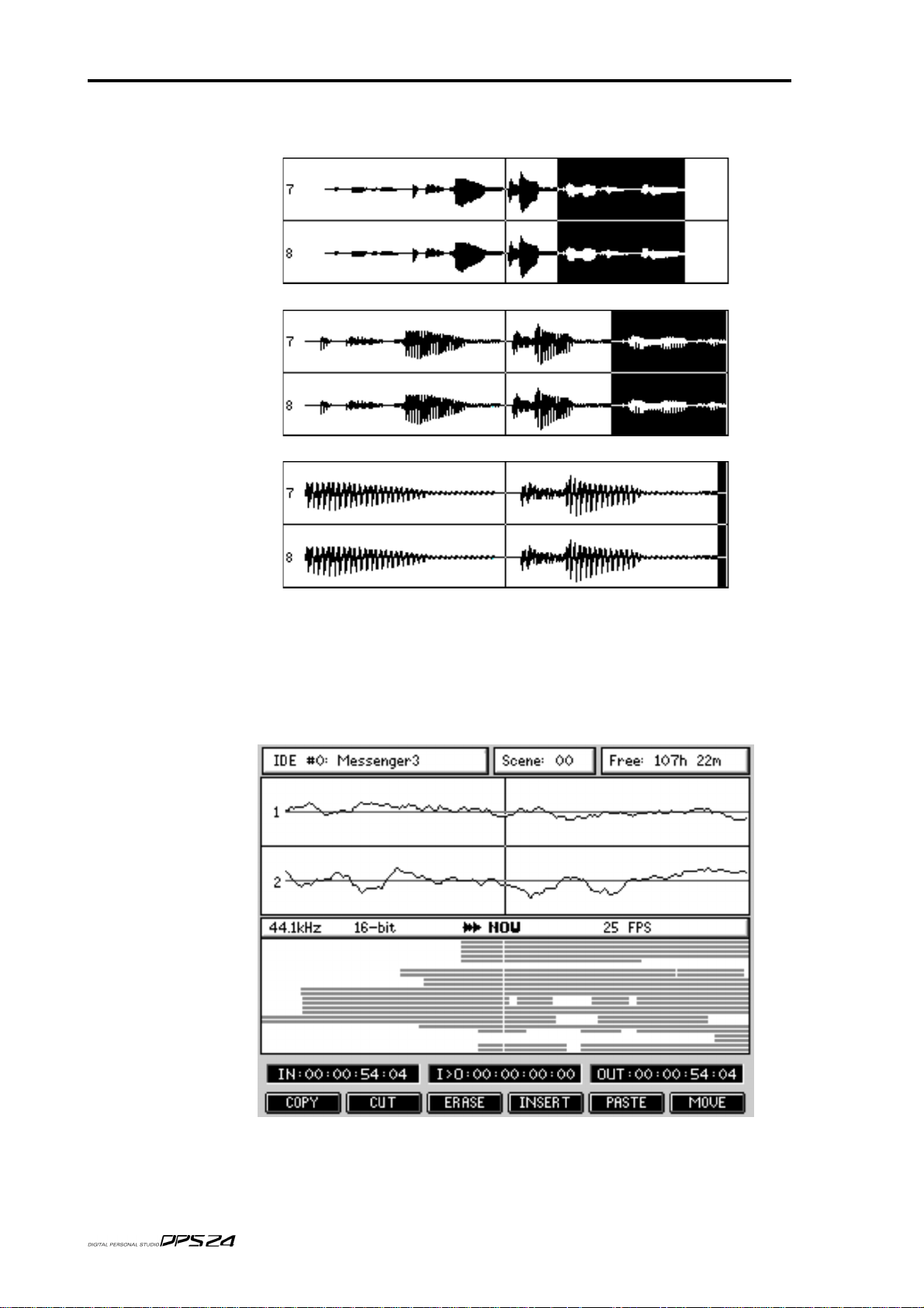
54
EDIT MODE
Using SHIFT+CURSOR LEFT/RIGHT , you may zoom in/out on the waveform horizontally:
At any resolution, you can use the numerical keypad's +/- keys or the Q5 knob, to nudge the
NOW time forwards or backwards by one pixel increments to fine tune your edit points.
At the maximum horizontal zoom, one pixel of the LCD represents one sample.This means
that you can set sample accurate edit points.
v1.6 Operator’s Manual
Page 67

EDIT MODE
From the main EDIT mode, the F1-F6 softkeys provide access to the individual edit function pages.
All EDIT function pages look more or less like this:
55
In all EDIT function pages, you can see a graphic representation of the selected EDIT function.
The Edit Tracks graphic shows you which tracks are selected for edit (same as the 24
RECORD/EDIT SELECT keys).
The CLEAR (F3) and ALL (F4) buttons give you a quick way of deselecting or selecting all tracks for edit.
F6 (or the ENTER key) performs the selected edit function and returns to the main EDIT screen.
CANCEL (F1) (or the CANCEL key) returns to the main EDIT screen without performing the edit.
Q5 selects the Automation Edit options.
v1.6 Operator’s Manual
Page 68

56
EDIT MODE
EDITING AND A UTOMA TION
When performing edits that cause audio to move, it is necessary to edit any automation data
that exists in that region accordingly. If automation data is left untouched by an audio edit,
the mix will be wrong. For example, when removing a piece of audio:
Without including the automation data in the edit, the fade is now in the wrong place.
Editing automation data with the audio edit means that the fade is still in the correct place
relative to the audio:
The editing functions on the DPS24 include a Q-LINK control that allows you to decide whether
automation data will be affected by the edit or not. This parameter exists on all the audio edit functions allowing you to decide how the automation will be affected when editing.
The options are:
OFF Automation data will not be carried with the audio edit.
SELECTED
ALL Automation for all channels will be carried with the audio edit. This
NOTE:
insert that edit with SELECTED chosen as the AUTOMA TION EDIT. In this case, your automation
data at the point of the insert will be potentially disrupted. If you perform an edit with ALL selected,
this should only then be used with PASTE/INSERT also set to ALL.
Care should be taken if you perform an edit with ALL selected and then attempt to paste/
Automation data on the tracks selected for editing will be carried with
the edit.
latter option is only useful if you are doing extensive multi-track editing (for example, editing all 24-tracks where you may also want the
mix of external instruments being sequenced through the Input channels to also be carried across with the edit).
v1.6 Operator’s Manual
Page 69

The edit functions are as follows:
COPY Pressing COPY [F1] displays this screen:
COPY
57
Pressing COPY [F6] or the ENTER key will copy the region to the clipboard from where it
may be subsequently pasted and/or inserted elsewhere in the project.
NOTE:
Select the track(s) you want to edit, mark your edit region and press COPY. Now load the project you
want to place the edit in, select the destination tracks and locate to the position you want the edit to be
placed and use the PASTE or INSERT function (explained later) to place the region in that project.
CUT and ERASE also copy the region to the clipboard so you can place audio regions you remove in
other projects as well.
Destination [Q2] allows to select between the regular Copy Region function (Clipboard) and
the Export Region function. The Export feature is described later in this manual.
Automation Edit [Q5] allows you to also copy the automation for that region.
It is possible to copy edits between projects that are stored on the same drive.
v1.6 Operator’s Manual
Page 70

58
EDIT MODE
CUT Pressing CUT[F2] displays this screen:
Pressing CUT [F6] or the ENTER key will remove the selected IN/OUT region to the clipboard and close the gap, shifting all subsequent audio backwards.
ERASE Pressing ERASE[F3] displays this screen:
Pressing ERASE [F6] or the ENTER key will remove the selected IN/OUT region to
the clipboard but subsequent audio will not slip in time.
v1.6 Operator’s Manual
Page 71

INSERT Pressing INSERT[F4] displays this screen:
INSERT
59
When pressing INSERT [F6] or the ENTER key, the contents of the clipboard are inserted at
the NOW time and all subsequent audio is shifted in time.
Y ou can specify the number of times the inserted cue will r epeat when inserted using Q5, No.
of Inserts. This will insert in the cue n times (up to 99) with each one appended to the end of
the previous one.
For example, with 4 repeats specified, you would get this result:
All audio after the point of insertion is shifted accordingly.
Pressing SILENCE [F5] allows you to insert a section of silence that is equal to the IN/OUT
region. All audio on the selected track(s) after the IN point will be slipped in time by the
IN>OUT length.
In this function, 'No. of Inserts' is ignored.
v1.6 Operator’s Manual
Page 72

60
EDIT MODE
P ASTE Pressing PASTE[F5] displays this screen:
When pressing PASTE [F6] or the ENTER key, the contents of the clipboar d is pasted in at the
NOW time. Please note, however, that the pasted audio will overwrite anything that exists
after the NOW time. If you make a mistake, you should use UNDO.
Using Q5, No. of Pastes, you may specify the number of times the pasted cue will be repeated (up to 99). However, the results are somewhat different than with INSERT:
NOTE:
Please consider this when pasting with repeats. If the action tramples over audio you want to keep,
don't forget that you can use UNDO!
Source [Q2] allows to select between the regular Paste Region function (Clipboard) and the
Import Region function. The Import feature is described later in this manual.
In this case, it could be that multiple repeats could paste over existing audio on the track.
v1.6 Operator’s Manual
Page 73

MOVE Pressing MOVE[F6] displays this screen:
MOVE
61
Here, you can slip/move the selected edit region to the NOW time referenced either to its IN
point or OUT point.
IN > NOW [F6] moves the IN/OUT region to start at the NOW time.
OUT > NOW [F5] moves the IN/OUT region to end at the NOW time.
Pressing MORE [F2] displays this screen:
v1.6 Operator’s Manual
Page 74

62
EDIT MODE
ORIGINAL Pressing F5 will move a recording to the timecode position at which it
was originally recorded.
NOTE 1:
place with respect to the first cue. This means you can edit or drop-in over a cue and then move the whole lot
back to the *cue's* original position whilst keeping the edits intact.
NOTE 2:
within the region being the significant one.
Any subsequent cues within the region on that track are moved such that they stay in the same
Each track is processed separately, so different tracks may end up in differ ent places, the first cue
TO TRACK Although easily achieved using ERASE and PASTE, this function al-
lows you to move audio from one track to another quickly and easily.
Pressing TO TRACK [F6] will pop up this prompt:
The source tracks are those selected for editing using the EDIT SELECT
keys before pressing TO TRACK [F6].
The destination tracks are those where you want the source tracks to be
moved to. To select the destination tracks, simply press the EDIT SELECT keys until the number of destination tracks corresponds to the
source tracks at which point the tracks will be moved. They will remain
at exactly the same timecode position.
How is this useful? The same function is possible using ERASE and
PASTE but the new MOVE TO TRACKS function achieves the same
result with fewer key presses.
v1.6 Operator’s Manual
Page 75

WAV/AIFF IMPORT
The DPS24 allows you to import audio files that have been recorded/edited on other systems. The IMPORT function is available in the EDIT mode in the PASTE and INSERT pages:
WAV/AIFF IMPORT
63
The Source on Q2 allows you to select the source of the PASTE / INSERT . By default, this is set to
CLIPBOARD and the paste / insert will be as normal from the DPS24's internal clipboard.
However, it is possible to use Q2 to select any of the installed or externally connected drives:
When a drive is selected (in the example shown above, the internal CD on IDE#1 is the
selected drive), F6 changes to show BROWSE. This allows you to see the contents of the
selected drive.
v1.6 Operator’s Manual
Page 76

64
EDIT MODE
Audio files can be imported from any connected drive, except the current Project drive.
The types of drives available are:
IDE#0 : Internal HD
IDE#1 :
SCSI#0-6 : External HD or External CD, (with the IB-24SCSI option board installed)
HOST#0-7 : Remote HD (when connected to a computer via USB, using akSysServer)
The drive formats that are recognized are:
CD-R : ISO9660 CDs Hard disk : FAT32
Removable media (such as ZIP disks) : FAT16
The file formats that can be imported are:
16 or 24bit Mono, Stereo or Multi-channel
WAV, Broadcast WAV (.wav or .bwf extensions) or AIFF files (.aif extension)
NOTE:
The DA TE RANGE parameter [Q4] allows you to select what files you will view when using
BROWSE, based on their creation date.
The options are:
The extension must be present for the DPS24 to recognize the file.
ALL You will see all files.
PAST YEAR You will only see files from the past year
PAST 6 MONTHS You will only see files from the past 6 months
PAST 2 MONTHS You will only see files from the past 2 months
PAST MONTH You will only see files from the past month
PAST 2 WEEKS You will only see files from the past 2 weeks
PAST WEEK You will only see files from the past week
TODAY You will only see files from the current date
Internal CD (or Internal HD if using a removable har d drive in place of the CD-R)
v1.6 Operator’s Manual
Page 77

WAV/AIFF IMPORT
Pressing BROWSE [F6] shows a screen that displays the files on the selected drive:
65
Folders on the disk are shown and these can be opened with the OPEN key on F5:
You will see the contents of the selected folder. In the example shown above, you can see the
.wav files listed. You can move the cursor up and down through the list to see the various files.
When the cursor is placed over a compatible audio file, the file information is displayed at
the bottom of the screen: Number of Channels, Sample Rate, Bit Depth, Length and Timestamp.
v1.6 Operator’s Manual
Page 78
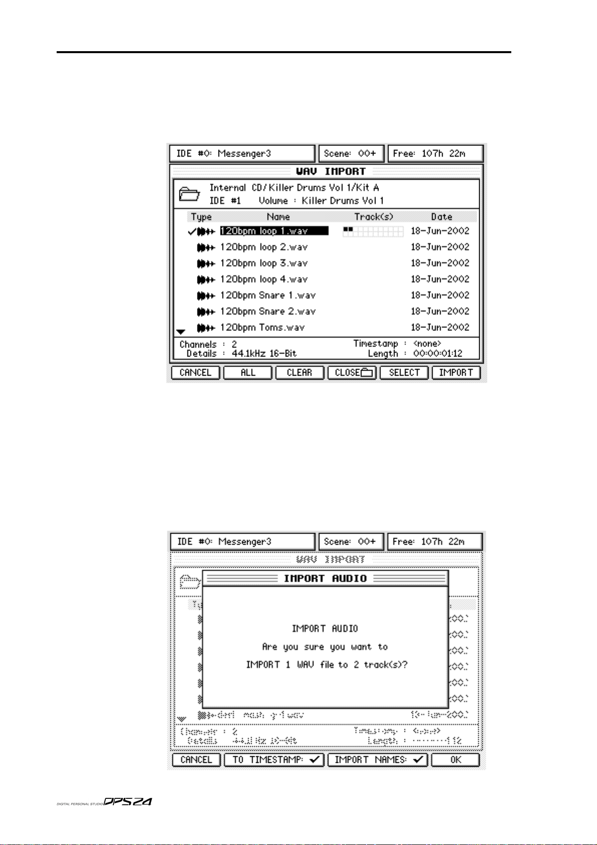
66
EDIT MODE
Once you have located the file that you wish to import, press SELECT [F5] to select it.
The selected file will be 'ticked' for confirmation.
To 'de-select' a file, either press SELECT again or press CLEAR [F3]
Also the destination tracks will be shown alongside the file selected for import:
Using the RECORD/EDIT SELECT keys, select the tracks to import the audio file to, so that
the number to selected tracks is at least equal to the number of Channels in the audio file.
If there are more tracks selected than the number of Channels, the file will be imported to the
lowest track numbers.
If there are less tracks enabled for EDIT than the number of Channels to be imported, the
following error message will be displayed:
Please select file(s) and destination tracks for import!
All you need to do now is press IMPORT. You will see something like this screen:
v1.6 Operator’s Manual
Page 79

You now have two options you can choose before you proceed.
WAV/AIFF IMPORT
67
TO TIMESTAMP [F2/F3]
IMPORT NAMES [F4/F5]
:
Allows you to have the .wav file automatically placed at its own original
timestamp within the DPS24 project. With Broadcast wavs (.wav or .bwf),
it is possible to store the timestamp information as part of the file. This is
not to be confused with the time of the day it was recorded (i.e. 2.15pm)
but the time/position in the project where it was recorded.
So, for example, if you recorded something in a three minute project
during the middle eight, it would have a timestamp of (say) 00:01:43.
Many (if not most) hard disk recording systems support this feature and
so, when importing files from other systems, the DPS24 can use these
timestamps so that the recordings you are importing are placed in exactly the same place in the DPS24 project as they were in the other system's
project. This feature is ideal for importing project from other systems,
especially when importing multiple .wavs from a multi-track project.
W e will look at this later when we discuss IMPORTING MULTITRACK
WAV FILES.
:
With this checked (i.e. 'ticked'), the file name will be imported and used
as the name for the track(s) the file is being imported onto.
For example, in the example shown above, tracks 1 and 2 will automatically be named "120bpm loop 1". this can be very useful when importing
material that will form an entire track but please note that if you are
importing several different files onto the same track (for example, importing sound effects one after each other on the same track), the track
name will be that of the most recently imported file.
Once you have made your selection, press OK.
When WAV/AIFF files are imported into a project, they are automatically re-sampled to the
project's sampling rate thus ensuring that they will play at the correct speed within the context of that project.
So, for example, if a 48kHz W AV is imported into a 44.1kHz project, the imported file will be
re-sampled down to 44.1kHz.
If you try to import a file that is at a different sample rate than the current project, you are
prompted the following message and you can respond accordingly:
One or more files are not
at the same sample rate as
project, these files will be
sample rate converted.
Continue?
Once the Import process starts, you will see a progress display as the file is imported to the
selected tracks.
At the end of the process, you will see a confirmation dialog - press OK [F6]
The import is done!
NOTE
: When importing a single file, you can (if you want) press IMPORT [F6] directly without
selecting it with SELECT [F5] first, if tracks are already selected for EDIT.
v1.6 Operator’s Manual
Page 80

68
EDIT MODE
IMPORTING MULTIPLE WAV FILES TO MULTIPLE TRACKS
Importing multiple .wav files to multiple tracks is pretty much the same as importing single files.
The DPS24 allows you to import up to 24 tracks in one pass.
To recap the import process, locate to the point where you want to import the files, press
EDIT and select the required number of tracks for edit. Go to PASTE or INSERT and select
the appropriate source drive that contains the files you want import. Press BROWSE and
navigate the disk to find the files you want to import:
To import multiple files, select them using the CURSOR keys and use the SELECT key to 'mark' them:
v1.6 Operator’s Manual
Page 81

IMPROTING MULTIPLE WAV FILES TO MULTIPLE TRACKS
Now, as you select each file, you will see an indication of the tracks that each file will end up
on shown to the right of the filename:
In the above example (which shows a typical application for multiple file insertion - importing projects made on other systems), the track are shown in descending order and so it would
make sense to put the various files on the same tracks as the DPS24.
However, you can set the tracks the file(s) will be allocated to simply by selecting them in or der.
So, for example, if for some reason you wanted to allocate the above as follows:
FILENAME DPS24 TRACKS
Tracks 1&2.wav Tracks 5 and 6
Tracks 3&4.wav Tracks 1 and 2
Tracks 5&6.wav Tracks 3 and 4
69
You would press the SELECT key in the following order:
1 Tracks 3&4.wav
2 Tracks 5&6.wav
3 Tracks 1&2.wav
And you would see this on the screen with the files allocated to the tracks accordingly:
When you're ready and you have selected all the files you want to import, simply press
IMPORT on F6.
As with importing a single file, you will receive a prompt asking you to confirm. You will
also have the option to select whether the files' timestamps (if any) are used and whether you
want to use the filenames as track names:
Only you can decide! However, if you ar e importing a pr oject fr om another system, it is quite
likely that all the files will be timestamped and so, to retain their relative synchronisation
when imported into the DPS24, it would be best to enable TO TIMESTAMP.
v1.6 Operator’s Manual
Page 82

70
EDIT MODE
Also, if you are importing projects from another system, it's quite likely that the tracks will
have been named so it might be wise to use IMPORT NAMES as well. Whatever you choose,
to import the files, press OK. You will see a progress display as the files are imported and at
the end of the process, you will see a confirmation dialogue - press OK [F6].
Importing multiple files in this way is ideal for working on projects that have been created
on other systems. Although the DPS24 cannot read their Q-Lists directly, being able to read
each file's timestamp on the DPS24 allows you to effectively re-create the Q-List from the
project on that system.
However, please note one thing...
It's quite possible that the original project created on the other system has several cues at
different times on one track:
Of course, all these small cues have unique timestamps but, because it is not possible to
assign more than one recording to any given DPS24 track, the individual files will need to be
spread across several tracks.
However , having said that, most systems should be able 'render' these individual recordings
as one long take that can be placed on one track (or a stereo pair) of the DPS24. I.e.
Many systems will render individual recordings by default.
v1.6 Operator’s Manual
Page 83

WAV/AIFF FILES EXPORT
The DPS24 also allows you to export audio recordings to an IDE or SCSI CD-R (ISO 9660) or
hard disk (FAT32/16), or to a computer via USB. You can export up to 24 tracks in one pass.
The export function is available as part of the COPY function in the EDIT pages.
The process is almost identical to copying audio within a project: select the track(s) you want
to export, mark an IN/OUT region, and copy it. The difference is that you are copying it to a
CD/HD instead of the internal clipboard.
To access the EXPORT function, press EDIT, press COPY [F1]. You will see this screen:
WAV/AIFF EXPORT
71
Using Q2, select the Destination drive you want to export the tracks to.
The available drive selections are the same as for Import (IDE, SCSI or HOST).
The display changes to the EXPORT REGION screen, according to the Destination selection:
Q4 allows you to select the Export Region options for the export.
The graphic on the EXPORT REGION page should give a clue to the end result.
v1.6 Operator’s Manual
Page 84

72
EDIT MODE
These options are:
START <> END
IN <> END
START <> OUT
IN <> OUT
When START<>END or START<>OUT is selected, each exported file will start only where
the actual audio begins, with the start position of the audio in the project stored as a sample
accurate timestamp attached to the WAV file (Broadcast WAV).
When IN<>END or IN<>OUT is selected, if the actual audio starts after the IN point, the
exported file will include "recorded" silence from the IN point to the start of the audio. Ther efore, all the files exported in the same pass will start exactly at the same point, allowing them
to line up when imported in a system that doesn't support Broadcast WAV timestamps.
One thing to note, is that all audio within any of the selected options will be 'rendered'. In
other words, if (for example) a particular track has a load of small, individual cues in the
original DPS24 project, when exported, that track will be one continuous .wav file.
For example:
Only the actual audio contained from the start of the first cue to the end
of the last cue within the IN/OUT region will be exported.
The audio between the marked IN point and the end of the actual audio
within the IN/OUT region will be exported.
The audio between the actual start of the audio within the IN/OUT
region and the marked OUT point will be exported.
The audio between the marked IN / OUT point will be exported.
Original track
The exported version
Q5 allows you to select the Export Type. The options are:
MONO Each of the selected tracks will be exported as individual, separate mono
timestamped files.
STEREO Disk channels that are paired as 'stereo' will have their recordings ex-
ported as stereo timestamped files. Those channels that aren't 'paired'
will still be exported as individual timestamped mono files.
MULTI-CHANNEL
To actually export the audio, press BROWSE. You might see "Please wait" for a few seconds.
This option will cause the selected tracks to be exported as a single multichannel .wav file.This is only appropriate for exporting entire projects
to other multi-track systems that support Multi-Channel W AV files (such
as the DPS16). However, please note... track-order is preserved. For example, if DPS24 edit tracks 1,2,4,5,6,11,12 are selected, these will map
to channels 1,2,3,4,5,6,7 of the multi-channel .wav file).
v1.6 Operator’s Manual
Page 85

WAV/AIFF EXPORT
If the selected drive is a hard drive (Internal, External or Remote HD), you will see this screen:
73
If the selected drive is a CD-R/RW drive, you will see this slightly different screen :
The main export features are identical but CD and HD drives have some specific functions.
In both cases, Q2 allows you to select the Export file Format, as WAV or AIFF.
AIFF is only intended for use with older Apple Macintosh based systems. However, the AIFF
file format does not include timestamps. Most current Macintosh based systems now support
WAV or Broadcast WAV files. When WAV is selected, the DPS24 exports Broadcast WAV files.
Q5 allows you to select the Export Region options.
Q6 allows you to select the Export Type options.
v1.6 Operator’s Manual
Page 86

74
EDIT MODE
Those options are the same as in the EXPORT REGION screen and are duplicated here for
convenience.
Also shown in the lower part of the display are:
Edit Tracks graphic
Free : shows the available space on the Destination disk
Size : shows a calculation of the total export size
Details: shows the Sample Rate and Bit Depth settings of the current Project.
NOTE:
When exporting, please note that the sample rate/bit depth of exported files is always defined
by the current Project settings.
Name: shows the export name (defaults to <auto>)
: shows which tracks are going to be exported
The export size is recalculated in real-time as the region selection (IN/
OUT points, Edit Tracks), Export Region and Type parameters are
changed. This way, you always know whether the current selection is
going to fit on the Destination disk or not.
Export files can be either explicitly named or auto-named.
The NAME key [F2] can be used to enter a specific name. If left blank, it
returns to auto-naming.
For named MONO or STEREO exports, the resultant filename has the
track number appended. Since MULTI-CHANNEL export will always
generate a single file only, nothing is appended to the name.
For auto-named MONO or STEREO exports, the resultant filename is
the Channel Name of the track (STEREO exports use the left channel
and remove 'L', if present, from the end of the Channel Name).
For auto-named MULTI-CHANNEL exports, the resultant filename is
simply the Project name.
Examples:
1. Named export 'T est Export' of tracks 1, 2, 3, 7, 11 (with tracks 1 + 2 paired):
MONO STEREO
Test Export 01.wav Test Export 01.wav (stereo file)
Test Export 02.wav Test Export 03.wav
Test Export 03.wav Test Export 07.wav
Test Export 07.wav Test Export 11.wav
Test Export 11.wav
MULTI-CHANNEL
Test Export.wav (5-channel file)
2. Auto-named export of tracks 1, 2, 3, 7, 11 (with tracks 1 + 2 paired):
MONO STEREO
Guitar 1 L.wav Guitar 1.wav (stereo file)
Guitar 1 R.wav Synth FX.wav
Synth FX.wav Lead Guitar.wav
Lead Guitar.wav Vocal.wav
Vocal.wav
MULTI-CHANNEL
Really Cool Project.wav (5-channel file)
v1.6 Operator’s Manual
Page 87

WAV/AIFF EXPORT
If a file already exists on the CD/harddisk with the same name as a file to be exported, a dialog
will pop-up allowing the user to auto-rename the file. Auto-renaming consists of appending an
incremental number onto the filename (e.g. 'export.wav' -> 'export 2.wav' -> 'export 3.wav').
For harddisks it is possible to overwrite the existing file by selecting NO [F5] at the auto-rename
prompt. It is NOT possible to overwrite files on a CD, instead, if NO is selected, the exported file
will have the same name as the existing file and will be inaccessible on most systems.
If there are already files on the Destination disk, you will see that data on the display.
If the selected drive is a HD drive, you will be able to browse the files and folders on that
disk, Open and Close folders using F4 and F5, create and rename folders and sub-folders,
and even rename or delete individual files via the UTILS [F3] menu.
If the selected drive is a CD drive, you will be able to EJECT [F5] the disc or ERASE [F4] the
disc if it is a CD-RW media.
If the selected drive is a CD drive, you can also see the type and status of the Disc at the top
right of the screen. The various types are: No Disc, Audio CD, Data CD, ISO9660 CD and the
various states are (Blank), (Open) or (Closed).
The DPS24 can only export audio files to ISO9660 CDs that are (Blank) or (Open).
With an ISO9660 CD, you will only see the Root directory of the disk, but you will be able to
add a Folder in the Root directory using MAKE [F3]. However, only a single level of folders
is supported for CD export.
75
If the selected drive is a CD drive, you will also be able to select SLOW or FAST Write Speed
[Q3] and to switch the Test Write mode ON/OFF [Q4].
When ready, just go ahead and export the selected tracks/region by pressing EXPORT [F6].
The following EXPORT AUDIO prompt will be displayed for confirmation, for instance:
Are you sure you want to
EXPORT 5 tracks to: 1 stereo file
and 3 mono files?
If you press OK [F1], the files will simply be written to the selected folder of the disk as
individual mono,stereo or multi-channel files.
The display will keep you informed of the progress of the Export process until Export is Completed.
v1.6 Operator’s Manual
Page 88

76
DSP MODE
DSP MODE
Pressing SHIFT+EDIT gives access to the off-line DSP functions:
As you can see, the screen layout is virtually identical to the main real-time EDIT screen.
Operation is also the same....
Jog over the point where you want the off-line edit to start and mark an IN point as appropriate. Do the same to mark the OUT point.
Once you are happy with the edit region you have created, you can select the DSP function
you wish to apply to it. This will display a window where you can set parameters appropriate to the selected DSP function using the Q-Link controls.
Unlike EDIT functions that only change pointers to the existing audio, off-line DSP functions
generate new 'processed' audio files on the disk.
As for EDIT, you can select as many tracks as you need to process.
However, please note that processing time increases proportionally as each track (or pair of
stereo tracks) is processed. For example, if processing a stereo track of X length takes Y seconds, processing two stereo tracks of the same length will take twice as long.
NOTE:
mono or stereo tracks, depending on whether the mixer channel is paired or not.
If the mixer channels for selected tracks are paired, the stereo DSP pr ocess will r emain phase-coher ent.
Time stretching/Pitch shifting/BPM matching/Varispeed process the tracks in sets of either
From the main DSP mode, the F1-F5 softkeys provide access to individual DSP function pages.
F6 [MORE] allows access to additional DSP functions.
Then, F6 [BACK] returns to the previous DSP menu.
v1.6 Operator’s Manual
Page 89

DSP MODE
TIMESTRETCH This allows you to expand/compress the length of the edit region with-
out changing its pitch.
Pressing STRETCH [F1] displays this screen:
Using Q2, you can select the timestretch preset. All the stretch-related DSP processes have a series of presets optimised for certain types of material. These are:
77
SPEECH 1 This works well on female speech.
SPEECH 2 This works well on male speech.
SPEECH 3 This is more appropriate for deeper male speech.
VOCAL This works well with solo and ensemble singing voices in isolation
and, in music studio applications would be applicable for processing backing vocals and the like.
DANCE 1 This works well with rhythmic material with little bass content
or bass content that is short.
DANCE 2 This works well with rhythmic material. HF and MF is handled
well and short as are sharp bass sounds.
DANCE 3 This is also suitable for r hythmic material but will handle longer
bass components better.
PERC 1 This works on very rhythmic material, especially solo drums,
etc., but can upset bass content.
PERC 2 This also works well on percussive material but can handle bass
content better.
HI NRG This works well processing material that is percussive, staccato
and rhythmic with a wide frequency range (although sustained
bass content may 'wobble').
BALLAD This works well on material that has long, sustained LF content.
Musically, it is effective for processing slow ballads and handles
long bass notes quite well but you may occasionally experience slight
'flamming' (i.e. double triggering) with some percussive sounds.
v1.6 Operator’s Manual
Page 90

78
DSP MODE
ROCK 1,2,3
SWING This works well on material with a wide frequency range that is
ALLEGRO 1 This works well on orchestral music with lively dynamic strings
ALLEGRO 2 This is optimised to handle bass content better.
ADAGIO This is better suited to slow orchestral material with long, sus-
Each preset has three variations A, B and C. The A variations make a more
general analysis of the original sound and although they process the selected
region more quickly, the end result may not be as accurate as using either the B
or C variations which make a more detailed analysis of the original material
(but take slightly longer to process).
Q2 - ADJUST - provides access to the key parameters in any one preset and
allows you to make adjustments to the preset with one, easy to use control.
Suitable for processing a wide range of musical styles that have
a broad band of bass and high frequency content and rhythmic
elements.
not too percussive.
and HF content.
tained notes.
Q3 - AMOUNT - allows you set the timestretch amount as a per centage with a
range of 50% - 200% (100% is 'absolute' and represents no change).
F2 [SLIP on/off] allows you to select whether audio after the timestretch region will slip in time or not. The key is a simple ON/OFF switch with status
being denoted by a simple (on) or (off).
Pressing PROCESS [F6] or the ENTER key will initiate the process. As with all
the off-line DSP functions, this will process the edit region and will automatically replace the original with the new processed version.
If you don't like the results, you should press UNDO.
The quality of the processed result will depend on the type of source audio
material, the selected Preset and the Adjust parameter. You might want to experiment with various Presets and different Adjust values to find the best settings for the audio that you are processing.
This becomes more noticeable when when increasing the amount over 100%.
When you press PROCESS [F6] or the ENTER key, you see this progress display:
v1.6 Operator’s Manual
Page 91

DSP MODE
The process can be aborted at any time by pr essing F1. This will leave the original untouched.
79
NOTE:
PITCH SHIFT
This progress display is shown for all the off-line editing processes.
Allows you to change the pitch of the selected edit region without changing its length.
Pressing PITCH [F2]displays this screen:
As in the TIMESTRETCH page, you may select a preset, adjust it manually.
But instead of the strech amount, here you set the tuning offset that you
want to apply.
PROCESS [F6], or the ENTER key, initiates the process.
Because the length of the processed version doesn't change, the SLIP
function key does not appear.
v1.6 Operator’s Manual
Page 92

80
DSP MODE
BPM This allows you to match the selected edit region to another tempo with-
out changing its pitch. This is exactly the same processs as T imestr etch,
but this allows to enter a Tempo instead of an amount in %.
Pressing BPM [F3] displays this screen:
V ARI-SPEED
As in the TIMESTRETCH page, you may select a preset, adjust it manually.
To match tempi, you need to know the tempo of the original audio.
This is entered in the SOURCE TEMPO field. You then need to set the
tempo you want the edit region to play at in the NEW TEMPO field.
PROCESS [F6], or the ENTER key, initiates the process.
F2 [SLIP] allows you to select whether audio after the tempo-matched
region will slip in time to accommodate the new length.
Allows you to speed up/down the selected edit region. The audio will
change pitch and length as though speeding up or slowing down a reel-toreel tape machine.
Pressing VARI [F4] displays this screen:
v1.6 Operator’s Manual
Page 93

DSP MODE
Here, you can only adjust the amount of varispeed using Q4.
V arispeed is a much simpler pr ocess than Timestretch or Pitch Shift and
thus does not require to select a Preset nor Adjust.
PROCESS [F6], or the ENTER key, initiates the process.
F2 [SLIP] allows you to select whether audio after the processed region
will slip in time to accommodate the varispeed.
Another application of the Varispeed feature is known as 'Rendering'
(also known as 'Consolidate Audio').
By setting the Amount to 100%, the speed and pitch of the selected audio region will remain unchanged, but if the region is composed of several smaller cues (as a result of editing or multiple recording punches),
this processs will create one continuous audio file instead.
81
REVERSE
Allows you to reverse the selected edit region so that it plays backwards.
Pressing REVERSE [F5] displays this screen:
There are no parameters to adjust for this function.
Because the length of the processed version doesn't change, the SLIP
function is not shown.
v1.6 Operator’s Manual
Page 94

82
DSP MODE
NORMALISE Allows you to normalise the selected edit region. The signal is analysed
for its peak level and the edit region is then increased proportionally to
obtain maximum level.
Pressing MORE [F6] followed by NORMAL [F1] displays this screen:
There are no parameters to adjust for this function and pressing PROCESS
will simply normalise the selected edit region bring it to maximum level.
NOTE:
the loudest section of audio on any of the selected tracks, so if tracks 1, 2, 3, 4, 5 and 6 are normalised and
there is a loud section on track 4, tracks 1, 2, 3, 5 and 6 will be normalised according to this audio level.
RESAMPLE Allows you to convert the sampling rate of the selected edit region.
When processsing multiple tracks simultaneously, Normalising always normalises according to
This also includes a dithering function to convert the Bit depth.
Pressing MORE [F6] followed by RESAMPLE [F2] displays this screen:
Here, you can set the original sample rate of the audio (From [Q3]) and
the new sample rate that you want to convert to (To [Q4]).
Using Q5 [Dither], you can also change the bit depth of the selected audio.
PROCESS [F6], or the ENTER key, initiates the process.
v1.6 Operator’s Manual
Page 95

DSP MODE
F2 [SLIP] allows you to select whether audio after the processed region
will slip in time to accommodate the varispeed.
The main application of the Resample feature is to convert the sample
rate of a region that is being pasted into a Project set at a differ ent sample
rate than the Project it was copied from.
This can also be used to dither a 44.1kHz/24bit stereo project down to
16bit before burning it to CD.
83
v1.6 Operator’s Manual
Page 96

84
MIXER MODE
MIXER MODE
Pressing the MIXER key shows this screen:
As in the MAIN screen, the top half of the MIXER screen shows the meters for the 12 inputs,
8 groups, 8 FX/AUX sends, 4 stereo FX returns and 24 disk tracks.
Under the meters block, you can see an overview of a selected parameter for all the channels.
The displayed parameter is selected using Q6. The default parameter is LEVEL, showing the
Fader position for all channels. This is useful as it allows you to see all faders in one glance,
without having to switch Fader Banks. You may also view different parameters, such as Pan,
Channel ON, FX/AUX Sends 1-4 or Stereo Linking.
Pan:
v1.6 Operator’s Manual
Page 97

Channel ON (Mute):
MIXER MODE
85
For this parameter, a clear circle indicates that the Channel is ON, while a black circle indicates that the Channel is OFF (muted).
FX/AUX Send:
v1.6 Operator’s Manual
Page 98

86
MIXER MODE
MIXVIEW
To see a more detailed overview of the mixer's status, pressing MIXVIEW [F2] in the main
MIXER page shows this:
Here, you can see the level, pan, mute status and FX/Aux send levels for the 24 disk tracks.
Pressing INPUTS/FX/GROUP (F3/4) shows this screen:
Here, you can see the same for the Inputs, FX/AUX send master levels, FX return and the 8 x
Group sends. The master fader or L/R meters are not shown as these are always visible on
the front panel. Neither of these pages are 'editable' as such - they merely r eflect the controls'
positions as set on the front panel and update in real-time as these controls are adjusted.
v1.6 Operator’s Manual
Page 99

CHANNEL
In the main MIXER page, pressing CHANNEL (F1) will show the settings for the selected channel.
CHANNEL
87
NOTE:
the selected Channel on the LCD. Then , when disabling Q-CHANNEL, the display returns to the
previous screen.
There are actually multiple Channel pages:
There are also several Channel types. The Channel types are:
Enabling the Q-CHANNEL button automatically calls up the MIXER / CHANNEL page of
EQ Channel page
Dynamics Channel pages:
Compressor/Expander sub-page
Noise Gate sub-page
Channel Utilities page
Input Channel (Mono)
Track Channel (Mono)
FX Return Channel (Stereo)
Aux L/R Input (Stereo)
Group
FX/AUX Master Send
Master Channel
MIDI Controller Channel
The Channel pages only show the parameters available for the type of selected channel.
For instance, only Mono Input or Track Channels have EQ and Dynamics controls.
The main EQ Channel page looks like this:
The main EQ Channel page is designed so that you can use the Q-Channel encoders to set
the main parameters (pan, EQ, sends, etc.) and the Q-Link controls to set the others.
v1.6 Operator’s Manual
Page 100

88
MIXER MODE
However, it is also possible to navigate the 'channel' window (i.e. pan, level, EQ, FX parameters) using the CURSOR keys or Q5. For the field that is selected by the cursor:
You can set precise values from the numeric keypad or using the DATA +/- keys.
You can also set values using the DATA ENTRY Q-Link control on Q6.
In the EQ Channel page, the Q-LINK parameters on the right of the page are as follows:
INPUT SOURCE If the selected channel is an Input channel, Q1 selects the input source.
The choices are:
ADC 1-12 FX 1 L
Digital In LFX 1 R
Digital In RFX 2 L
Aux In L FX 2 R
Aux In R FX 3 L
2-Track L FX 3 R
2-Track R FX 4 L
ADAT 1 - 8 FX 4 R
ADAT 9-24 METRO
In this way , you can patch any analogue or digital audio source to any input.
RECORD SOURCE
INPUT SOURCE If the selected channel is a stereo FX Return channel, Q1 selects the in-
PHASE INVERT Q2 inverts the phase of the channel.
If the selected channel is a T rack channel, Q1 selects the Disk Record source.
The choices are the same as the Input Channel's Input sources, plus:
INP 1-12 Stereo L
Group 1-8 Stereo R
- - - - - (no assignment)
put source pair.
The choices are:
FX1 L+R Digital In L+R
FX2 L+R Aux In L+R
FX3 L+R 2-Track L+R
FX4 L+R ADAT 1+2
ADC1+2 ADAT 3+4
ADC3+4 ADAT 5+6
ADC5+6 ADAT 7+8
ADC7+8 ADAT 9+10
ADC9+10 ... up to ...
ADC11+12 ADAT 23+24
This is available only for Mono Input and Track Channels.
ATTENUATION
METER
v1.6 Operator’s Manual
Q3 is simple attenuator to compensate for any excessive gain boosts in the EQ.
This is available only for Mono Input and Track Channels.
Q4 allows you to set where in the audio chain you will view the meter shown
to the right of the fader . The options ar e PRE-EQ, PRE-F ADE and POST -FADE.
This is available only for Mono Input, Track and FX Return Channels.
 Loading...