

DIGITAL PERSONAL STUDIO
Software Version V2.1
WARNING
To prevent fire or shock hazard, do not
expose this appliance to rain or moisture.
Operator’ s Manual
WARNING!!
To prevent fire or shock hazard, do not expose this appliance to rain or moisture.
CAUTION
RISK OF ELECT RIC SHOCK
DO NOT OPEN
CAUTION: TO REDUCE THE RISK OF ELECTRIC SHOCK,
DO NOT REMOVE COVER (OR BACK).
NO USER-SERVICEABLE PARTS INSIDE.
REFER SERVICING TO QUALIFIED SERVICE PERSONNEL.
THE SYMBOLS ARE RULED BY UL STANDARDS (U.S.A.)
The lightning flash with arrowhead symbol , within an equilateral triangle, is intended to
alert the user to the presence of uninsulated “dangerous voltage” within the product’s
enclosure; that may be of sufficient magnitude to constitute a risk of electric shock to
persons.
The exclamation point within an equilateral triangle is intented to alert the user to the
presence of important operating and maintenance (servicing) instructions in the literature
accompanying the appliance.
1-En
5B-En
03/15/2000Rev. 3

WARNING
WARNING: WHEN USING ELECTRIC PRODUCTS, BASIC PRECAUTIONS SHOULD ALWAYS BE FOLLOWED, INCLUDING THE FOLLOWING:
WARNING
The DPS12 is designed to be used in a standard household environment.
Power requirements for electrical equipment vary from area to area. Please ensure that your DPS12 meets
the power requirements in your area. If in doubt, consult a qualified electrician or Akai Professional dealer.
120 VAC @ 60 Hz for USA and Canada
220~240 VAC @ 50 Hz for Europe
PROTECTING YOURSELF AND THE DPS12
• Never touch the AC plug with wet hands.
• Always disconnect the DPS12 from the power supply by pulling on the plug, not the cord.
• Allow only an AKAI professional dealer or qualified professional engineer to repair or reassemble the
DPS12. Apart from voiding the warranty, unauthorized engineers might touch live internal parts and receive
a serious electrical shock.
• Do not put, or allow anyone to put any object, especially metal objects, into the DPS12.
• Use only a household AC power supply. Never use a DC power supply.
• If water or any other liquid is spilled into or onto the DPS12, disconnect the power, and call your dealer.
• Make sure that the unit is well-ventilated, and away from direct sunlight.
• To avoid damage to internal circuitry, as well as the external finish, keep the DPS12 away from sources of
direct heat (stoves, radiators, etc.).
• Avoid using aerosol insecticides, etc. near the DPS12. They may damage the surface, and may ignite.
• Do not use denaturated alcohol, thinner or similar chemicals to clean the DPS12. They will damage the
finish.
• Modification of this equipment is dangerous, and can result in the functions of the DPS12 being impaired.
Never attempt to modify the equipment in any way.
• Make sure that the DPS12 is always well-supported when in use (either in a specially-designed equipment
rack, or a firm level surface).
• In order to assure optimum performance of your DPS12, select the setup location carefully, and make sure
the equipment is used properly. Avoid setting up the DPS12 in the following locations:
1. In a humid or dusty environment
2. In a room with poor ventilation
3. On a surface which is not horizontal
4. Inside a vehicle such as a car, where it will be subject to vibration
5. In an extremely hot or cold environment
i

WARNING
WARNING
THIS APPARATUS MUST BE EARTHED
IMPORTANT
This equipment is fitted with an approved non-rewireable UK mains plug.
To change the fuse in this type of plug proceed as follows:
1) Remove the fuse cover and old fuse.
2) Fit a new fuse which should be a BS1362 5 Amp A.S.T.A or BSI approved type.
3) Refit the fuse cover.
If the AC mains plug fitted to the lead supplied with this equipment is not suitable for your type of AC outlet
sockets, it should be changed to an AC mains lead, complete with moulded plug, to the appropriate type.
If this is not possible, the plug should be cut off and a correct one fitted to suit the AC outlet. This should
be fused at 5 Amps.
If a plug without a fuse is used, the fuse at the distribution board should NOT BE GREATER than 5 Amp.
PLEASE NOTE: THE SEVERED PLUG MUST BE DESTROYED TO AVOID A POSSIBLE
SHOCK HAZARD SHOULD IT BE INSERTED INTO A 13 AMP SOCKET
ELSEWHERE.
The wires in this mains lead are coloured in accordance with the following code:
GREEN and YELLOW —EARTH
BLUE —NEUTRAL
BROWN —LIVE
As the colours of the wires in the mains lead of this apparatus may not correspond with the coloured
markings identifying the terminals in your plug, please proceed as follows:
The wire which is coloured GREEN and YELLOW must be connected to the terminal which is marked
with the letter E or with the safety earth symbol or coloured GREEN or coloured GREEN and
YELLOW.
The wire which is coloured BLUE must be connected to the terminal which is marked with the letter
N or coloured BLACK.
The wire which is coloured BROWN must be connected to the terminal which is marked with the letter
L or coloured RED.
THIS APPARATUS MUST BE EARTHED
Ensure that all the terminals are securely tightened and no loose strands of wire exist.
Before replacing the plug cover, make certain the cord grip is clamped over the outer sheath of the lead
and not simply over the wires.
6D-En
ii

WARNING
VENTILATION
Do not prevent the unit's ventilation, especially by placing the unit on the soft carpet, in a narrow space,
or by placing objects on the unit's chassis—top, side, or rear panels. Always keep the unit's chassis at least
10 centimeters from any other objects.
31C-En
CHANGES OR MODIFICATIONS NOT EXPRESSLY APPROVED BY THE MANUFACTURER FOR
COMPLIANCE COULD VOID THE USER’S AUTHORITY TO OPERATE THE EQUIPMENT.
32-En
FCC WARNING
This equipment has been tested and found to comply with the limits for a Class B digital device pursuant
to Part 15 of the FCC rules. These limits are designed to provide reasonable protection against harmful
interference in a residential installation. This equipment generates, uses, and can radiate radio frequency
energy and, if not installed and used in accordance with the instructions, may cause harmful interference
to radio communications. However, there is no guarantee that interference will not occur in a particular
installation. If this equipment does cause harmful interference to radio or television reception, which can
be determined by turning the equipment off and on, the user is encouraged to try to correct the interference
by one or more of the following measures:
• Reorient or relocate the receiving antenna.
• Increase the separation between the equipment and receiver.
• Connect the equipment into an outlet on a circuit different from that to which the receiver is connected.
• Consult the dealer or an experienced radio/TV technician for help.
21B-En
This digital apparatus does not exceed the Class B limits for radio noise emissions from digital apparatus
set out in the Radio Interference Regulations of the Canadian Department of Communications.
27-En
AVIS POUR LES ACHETEURS CANADIENS DU DPS12i
Le présent appareil numérique n’ément pas de bruits radioélectriques dépassant les limites applicables
aux appareils numériques de la Class B prescrites dans le Règlement sur le brouillage radioélectrique
édicté par le ministère des Communications du Canada.
COPYRIGHT NOTICE
The AKAI DPS12 is a computer-based device, and as such contains and uses software in DISKs and ROMs.
This software, and all related documentation, including this Operator’s Manual, contain proprietary information
which is protected by copyright laws. All rights are reserved. No part of the software or its documentation may
be copied, transferred or modified. You may not modify, adapt, translate, lease, distribute, resell for profit or
create derivative works based on the software and its related documentation or any part there of without prior
written consent from AKAI professional M.I. Corp., Yokohama, Japan.
27-F
iii

WARNING
WARRANTY
AKAI professional M.I. Corp. warrants its products, when purchased from an authorized “AKAI professional”
dealer, to be free from defects in materials and workmanship for a period of 12 (twelve) months from the date
of purchase. Warranty service is effective and available to the original purchase only, and only on completion
and return of the AKAI professional Warranty Registration Card within 14 days of purchase.
Warranty coverage is valid for factory-authorized updates to AKAI instruments and their software, when their
installation is performed by an authorized AKAI professional Service Center, and a properly completed
Warranty Registration has been returned to your “AKAI professional” dealer.
To obtain service under this warranty, the product must, on discovery of the detect, be properly packed and
shipped to the nearest AKAI professional Service Center. The party requesting warranty service must provide
proof of original ownership and date of purchase of the product.
If the warranty is valid, AKAI professional will, without charge for parts or labor, either repair or replace the
defective part(s). Without a valid warranty, the entire cost of the repair (parts and labor) is the responsibility
of the product's owner.
AKAI professional warrants that it will make all necessary adjustments, repairs and replacements at no cost
to the original owner within 12 (twelve) months of the purchase date if:
1) The product fails to perform its specified functions due to failure of one or more of its components.
2) The product fails to perform its specified functions due to defects in workmanship.
3) The product has been maintained and operated by the owner in strict accordance with the written
instructions for proper maintenance and use as specified in this Operator's Manual.
Before purchase and use, owners should determine the suitability of the product for their intended use, and
owner assumes all risk and liability whatsoever in connection therewith. AKAI professional shall not be liable
for any injury, loss or damage, direct or consequential, arising out of use, or inability to use the product.
The warranty provides only those benefits specified, and does not cover defects or repairs needed as a result
of acts beyond the control of AKAI professional, including but not limited to:
1) Damage caused by abuse, accident, negligence. AKAI professional will not cover under warranty any
original factory disk damaged or destroyed as a result of the owner's mishandling.
2) Damage caused by any tampering, alteration or modification of the product: operating software, mechanical
or electronic components.
3) Damage caused by failure to maintain and operate the product in strict accordance with the written
instructions for proper maintenance and use as specified in this Operator's Manual.
4) Damage caused by repairs or attempted repairs by unauthorized persons.
5) Damage caused by fire, smoke, falling objects, water or other liquids, or natural events such as rain, floods,
earthquakes, lightning, tornadoes, storms, etc.
6) Damage caused by operation on improper voltages.
IMPORTANT NOTE: This warranty becomes void if the product or its software is electronically
modified, altered or tampered with in any way.
AKAI professional shall not be liable for costs involved in packing or preparing the product for shipping, with
regard to time, labor, or materials, shipping or freight costs, or time or expense involved in transporting the
product to and from AKAI professional Authorized Service Center or Authorized Dealer.
AKAI professional will not cover under warranty an apparent malfunction that is determined to be user error,
or owner's inability to use the product.
THE DURATION OF ANY OTHER WARRANTIES, WHETHER IMPLIED OR EXPRESS, INCLUDING BUT
NOT LIMITED TO THE IMPLIED CONDITION OF MERCHANTABILITY, IS LIMITED TO THE DURATION OF
THE EXPRESS WARRANTY HEREIN.
AKAI professional hereby excludes incidental or consequential damages, including but not limited to:
iv
1) Loss of time.
2) Inconvenience
3) Delay in performance of the Warranty.
4) The loss of use of the product.
5) Commercial loss.
6) Breach of any express or implied warranty, including the Implied Warranty of Merchantability, applicable to
this product.

Table of contents
Chapter 1: Outline of the DPS12 ..........................................1
Features of the DPS12....................................................................................................1
Parts and functions..........................................................................................................2
Top panel..................................................................................................................2
Front panel ...............................................................................................................5
Rear panel................................................................................................................5
Using a drive ...................................................................................................................6
Notes on using a drive.....................................................................................................6
About external SCSI devices...........................................................................................7
Connecting an external SCSI device .......................................................................7
About Projects .................................................................................................................9
About physical tracks and virtual tracks ..........................................................................9
TRACK MIX channels and THRU MIX channels...........................................................10
About a scene memory .................................................................................................13
About DPS12’s user interface .......................................................................................13
Using the display....................................................................................................13
Changing a setting or a value ................................................................................16
Table of contents
Chapter 2: Recording on the DPS12..................................19
Connections ..................................................................................................................19
Preparing to record........................................................................................................21
Turning on the power to the DPS12.......................................................................21
Formatting a disk....................................................................................................21
Creating a new Project...........................................................................................23
MAIN screen and TRACK VIEW screen .......................................................................24
MAIN screen ..........................................................................................................24
TRACK VIEW screen .............................................................................................25
Recording the first track ................................................................................................26
Recording signal flow .............................................................................................26
Recording to the first track .....................................................................................27
Using a locate point.......................................................................................................29
Overdubbing..................................................................................................................30
Overdubbing signal flow.........................................................................................30
Overdub operation .................................................................................................31
Using the Undo/Redo functions.....................................................................................31
Undo level = 1 (default setting) ..............................................................................31
Undo level = 2 or higher .........................................................................................32
Punch In/Out .................................................................................................................32
Mixdown ........................................................................................................................34
Mixdown signal flow ...............................................................................................34
Mixdown procedure................................................................................................35
Using Mixer mode ..................................................................................................35
Completing the operation on the DPS12.......................................................................37
v

Table of contents
Chapter 3: Transport/Locate operation .............................38
Transport operation .......................................................................................................38
Transport button operation.....................................................................................38
Using the [JOG] dial and the [SHUTTLE] dial ........................................................38
Using [TO] key and [FROM] key ............................................................................40
Locate operation............................................................................................................41
Storing locate points...............................................................................................41
Moving to a locate point .........................................................................................42
Locating the zero position of the time counter .......................................................42
Locating the end point of a song ............................................................................43
Deleting a locate point from the locate list .............................................................43
Using the Quick Locate function ............................................................................44
Repeat function ......................................................................................................45
Using the [IN] and [OUT] keys to play data between the [IN] point
and the [OUT] point................................................................................................46
Pre-Locate..............................................................................................................46
Post-Locate ............................................................................................................46
Entering a time value in the counter.......................................................................47
Chapter 4: Punch In/Out...................................................... 48
Manual Punch In/Out.....................................................................................................48
Punch In/Out operation using the transport buttons...............................................48
Punch In/Out operation using a foot switch............................................................49
Auto Punch In/Out .........................................................................................................50
Punch In/Out Rehearsal ................................................................................................51
Chapter 5: Assigning Input Signals and Virtual Tracks
(Assign Mode).....................................................52
About Assign mode .......................................................................................................52
Switching between TRACK MIX and THRU MIX (THRU) .............................................52
Assigning input sources to tracks (SOURCE) ...............................................................54
Assigning a virtual track to a physical track...................................................................56
TRACK ERASE function ........................................................................................57
Chapter 6: Mixer Function (Mixer Mode) ...........................58
About Mixer mode .........................................................................................................58
Basic operation in Mixer mode ......................................................................................58
Level/pan settings .........................................................................................................61
LEVEL ....................................................................................................................61
P A N ........................................................................................................................61
Equalizer settings ..........................................................................................................62
Turning the equalizer on/off (EQ ON/OFF) ............................................................62
Setting the frequency rate (EQ HIGH/MID/LOW FREQ)........................................62
Setting the level (EQ HIGH/MID/LOW LEVEL) ......................................................63
Setting the band width (EQ MID WIDTH)...............................................................63
Displaying all EQ parameters of a given channel (STRIP)............................................64
AUX send settings.........................................................................................................64
● When “2 MONO” is selected: .................................................................................64
Send level setting (AUX SEND-A(B)).....................................................................64
vi

Table of contents
Selecting PRE/POST (AUX A (B) PRE/POST).......................................................65
● When “STEREO” is selected:.................................................................................66
Send pan setting (AUX SEND PAN) ......................................................................66
Send level setting (AUX SEND LEVEL).................................................................66
Selecting PRE/POST (AUX PRE/POST) ...............................................................67
Other settings ................................................................................................................67
SETUP ...................................................................................................................67
Extra Bus................................................................................................................68
Channel ON/OFF (CHANNEL)...............................................................................69
MIDI settings (MIDI CONTROL).............................................................................69
GLOBAL.................................................................................................................70
SCENE MEMORY.........................................................................................................71
Storing a scene ......................................................................................................71
Recalling a scene...................................................................................................71
Erasing a scene .....................................................................................................72
Chapter 7: Advanced technique for mixing ......................73
Mixing and recording several input signals ...................................................................73
Mixing several inputs via AUX.......................................................................................74
Digital input from an external device .............................................................................75
Using the Solo function .................................................................................................76
Using virtual tracks ........................................................................................................78
Digital ping-pong recording ...........................................................................................79
Using an external effect unit for mixdown .....................................................................80
Adding sounds during mixdown ....................................................................................81
Chapter 8: Edit technique (Edit mode) ..............................82
Using an Edit mode screen ...........................................................................................82
Basic operations in Edit mode.......................................................................................83
Type and function of edit commands.............................................................................84
COPY PASTE .................................................................................................84
COPY INSERT................................................................................................85
CUT PASTE ....................................................................................................86
CUT INSERT ..................................................................................................86
INSERT SILENCE..................................................................................................86
CUT DISCARD ...............................................................................................87
CUT MOVE .....................................................................................................87
TIME STRETCH.....................................................................................................87
STRETCH INSERT ................................................................................................87
Chapter 9: Control Panel.....................................................89
Basic operation of the Control Panel.............................................................................89
Control Panel parameters .............................................................................................89
AUTO PUNCH (Setting Auto Punch In/Out points) ................................................89
VARI PITCH ...........................................................................................................90
TIME DISPLAY (Setting the time counter display) .................................................91
TIME OFFSET (offset of relative time)...................................................................92
TO/FROM TIME (time settings for the [TO] key and [FROM] key).........................93
PLAY MONITOR (selecting a monitoring source during playback) ........................93
Sync (synchronization)...........................................................................................94
vii

Table of contents
Chapter 10: Project management (Project mode) ............99
SAMPLING RATE ..................................................................................................95
BEAT MAP .............................................................................................................95
TEMPO MAP..........................................................................................................96
FOOT SWITCH ......................................................................................................97
MIDI (Selecting a function of the MIDI OUT/THRU jack) .......................................97
LCD CONTRAST ...................................................................................................97
OTHER (other setting) ...........................................................................................98
CD-R/RW SETUP ..................................................................................................98
What is a Project? .........................................................................................................99
Using the Project mode screen .....................................................................................99
Creating a new Project ................................................................................................100
Recalling a Project ......................................................................................................101
Erasing a Project .........................................................................................................101
Backing up a Project to an external device .................................................................102
Backup to CD-R/RW ............................................................................................103
Reloading the backup Project .....................................................................................105
Chapter 11: Using a disk (Disk mode) .............................107
Notes on handling a disk .............................................................................................107
Using the Disk mode screen .......................................................................................107
Changing the current drive ..........................................................................................108
Viewing the drive information ......................................................................................109
Formatting a disk.........................................................................................................110
Defragmenting a disk .................................................................................................. 111
Copying data in the disk .............................................................................................. 112
Using a removable drive.............................................................................................. 113
CD-R/RW Drive .................................................................................................... 113
CD-R/RW Mode ................................................................................................... 113
Drive Information.................................................................................................. 114
Making an Audio CD ............................................................................................ 115
writing a Disc ........................................................................................................ 115
Finishing disc write ............................................................................................... 115
Playing Back the Audio CD .................................................................................. 116
Erasing Data from a CD-RW disc......................................................................... 117
Chapter 12: MIDI applications .......................................... 118
Synchronizing an external device to the DPS12 (MTC) .............................................. 118
Synchronizing an external device to the DPS12 (MIDI Clock) .................................... 119
Synchronizing the DPS12 to an external device (MTC) ..............................................122
Controlling the DPS12 remotely from an external device (MMC)................................123
Recording and playing back a scene memory of the mix parameters.........................124
Recording and playing back a mix automation............................................................125
DPS12 MIDI Control Change Assign Table ..........................................................127
viii

Table of contents
Chapter 13: Using the effects...........................................128
Effect signal flow .........................................................................................................128
Global effects and Insert effects..................................................................................128
Using effects for mixdown ...........................................................................................129
Selecting an effect type........................................................................................129
Using effect return signals as analog inputs.........................................................130
Routing effect return signals to THRU MIX channels...........................................132
Setting the effect send level .................................................................................132
Adjusting the effect return level............................................................................133
Recording sound to a track while applying an Insert effect .........................................134
Effect type and parameter ...........................................................................................137
MONO CHORUS (G) ...........................................................................................137
STEREO CHORUS (G)........................................................................................137
XOVER CHORUS(G)...........................................................................................138
MONO FLANGER (G)..........................................................................................138
STEREO FLANGER (G) ......................................................................................138
XOVER FLANGER (G) ........................................................................................139
PAN FLANGER (G) ..............................................................................................139
MONO PHASER (I)..............................................................................................140
STEREO PHASER (I) ..........................................................................................140
XOVER PHASER (I) ............................................................................................140
PAN PHASER (I) ..................................................................................................141
PITCH SHIFT (I)...................................................................................................141
ROTARY SPEAKER (I) ........................................................................................142
AUTO PAN (I).......................................................................................................142
TRIGGER PAN (I) ................................................................................................143
MONO DELAY (G) ...............................................................................................143
PING PONG DELAY (G) ......................................................................................143
PANNING DELAY (G) ..........................................................................................144
STEREO DELAY (G)............................................................................................144
XOVER DELAY (G) ..............................................................................................144
TAPE ECHO (G)...................................................................................................145
REVERB>SMALL ROOM (Small Room Reverb) (G)...........................................145
REVERB>BIG ROOM (Big Room Reverb) (G) ....................................................145
REVERB>SMALL HALL (Small Hall Reverb) (G) ................................................146
REVERB>BIG HALL (Big Hall Reverb) (G)..........................................................146
REVERB>NON-LINEAR (Non-linear Reverb) (G) ...............................................147
REVERB>REVERSE (Reverse Reverb) (G)........................................................147
COMPRESSOR/LIMITER (I)................................................................................147
EXPANDER (I) .....................................................................................................148
NOISE GATE (I) ...................................................................................................148
DIGITAL EQ (I) .....................................................................................................148
AUTOWAH (I).......................................................................................................149
TOUCH WAH (I)...................................................................................................149
CHORUS>DELAY (G)..........................................................................................149
FLANGE>DELAY (G) ...........................................................................................150
PHASER>DELAY (G)...........................................................................................150
REVERB>STUDIO (G).........................................................................................150
REVERB>LIVE HOUSE (G).................................................................................151
REVERB>MEDIUM HALL (G)..............................................................................151
REVERB>BRIGHT HALL (G)...............................................................................151
ix

Table of contents
Appendix..............................................................................153
Specifications ..............................................................................................................153
MIDI Implementation Chart .........................................................................................155
IDE/SCSI Conversion Kit.............................................................................................156
x

Chapter 1: Outline of the DPS12
Chapter 1: Outline of the DPS12
➸
Note:
This manual has been prepared based on the DPS12 . Please read DPS12 in the manual as DPS12i,
unless otherwise noted specifically.
This chapter describes the features of the DPS12 and the name of its parts and functions. It also describes
the DPS12’s unique conceptual design and operating method. AKAI professtional recommends that you
read this chapter thoroughly even though you may already be quite familiar with multitrack recorders and
mixing consoles.
Features of the DPS12
The DPS12 has the following features:
• The DPS12 includes a hard disk recorder that enables you to perform 12-track recording/playback,
and a 20-channel digital mixer. You can record and mix down on a single DPS12 as if you were using
a multitrack recorder.
• The DPS12 provides you with 12 recording/playback tracks (physical tracks) and 250 data storage
tracks (virtual tracks). Switching among virtual tracks that are assigned to physical tracks allows you to
record multiple takes of the same part or phrase and later select the best take for mixdown.
• The mixer section is fully loaded with EQ, Pan, two AUX sends, and Level capabilities. In addition to 12
TRACK MIX channels that control the output from the recorder tracks, 8 THRU MIX channels are
available to directly control input signals from the INPUT jacks.You can mix down the signal from a
connected synthesizer, tone module, and/or external ef fect processor while playing back 12 tracks on
the recorder section.
• Up to six external hard disks and/or MO drives can be connected to the SCSI connector for backup and
recording.
• Connecting a MIDI device, such as a MIDI sequencer, allows for sync master or slave operation. Using
MMC (MIDI Machine Control) also enables you to remote-control the DPS12 from a connected external
device.
• Up to 100 locate points in songs can be named and stored. Y ou can immediately jump to any specified
locate point with an easy operation. A “Quick Locate function” that assigns locate points to the keys on
the front panel is also available.
• The DPS12 offers an improved and integrated edit function. You can specify track(s) to edit, and the
range of various editing operations, such as Copy & Paste, Cut & Paste, and Copy & Insert.
• The DPS12 is equipped with a scene memory that stores mix settings. You can create several mix
configurations with different balance and EQ settings. You can also adjust the mix-related parameters
via MIDI. Combining this with a MIDI sequencer will enable a mix automation.
• The internal effect board, EB2M, will provide you with two-channel, internally-connected digital effects.
This enables you to handle all signals, from recording through the application of effects to mixdown, in
the digital domain.
1
Chapter 1: Outline of the DPS12
Parts and functions
This section describes the part names and functions. The names of the controls on the top panel are
shown in brackets [ ].
Top panel
1 2 3 4 5 6
INPUT
1
INPUT GAIN
OVER
OVER
OVER
3
4
MICLINE
MICLINE
MICLINE
CHANNEL SELECT
3
4
C
R
5
C
C
R
L
R
L
5
MICLINE
RECORD SELECT
6
C
R
L
OVER
QUICK LOCATE
7
C
L
6
MICLINE
H
8
C
R
R
L
L
2
3
4
5
6
OVER
OVER
1
2
MICLINE
12345678
ABCDEFG
12345678
12345678
1
2
C
C
R
L
R
L
L
12345678
7
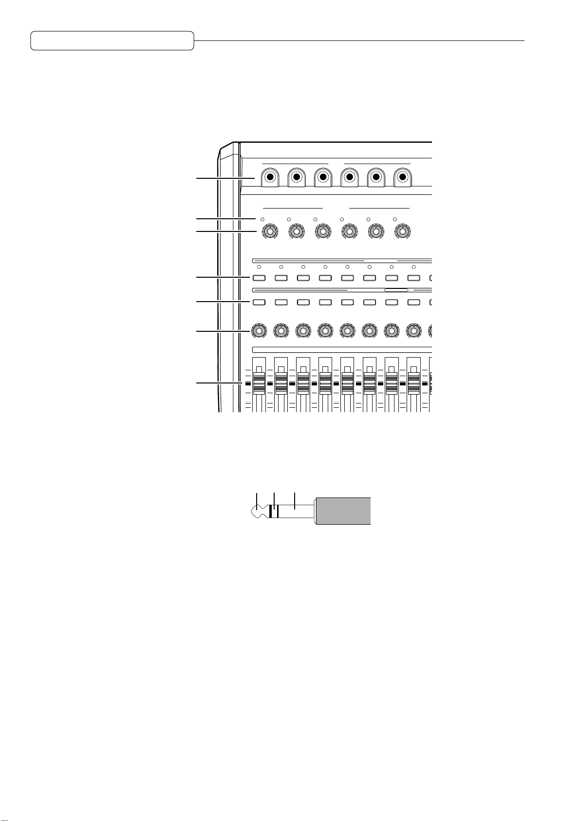
1 INPUT jacks 1–6
Connect line-level electronic instruments, such as a synthesizer, and microphones to these analog
input jacks. The signal input from these jacks will be routed to the tracks of the recorder section or to
the mixer section, depending on the settings. These input jacks accept balanced stereo signals.
GroundColdHot
Balanced signal input
2 Peak indicators
These indicators light up when the signals input from the INPUT jacks 1–6 clip.
3 [INPUT GAIN] controls 1–6
Use these controls to adjust the gain of the signals input from the INPUT jacks 1–6.
4 [RECORD SELECT] keys
Use these keys to select a recording track (physical track). When these keys are turned on, the LEDs
above them flash, indicating that the corresponding tracks enter recording-standby mode. Pressing the
keys again will cancel the standby mode. When the [SOLO] key (mr) is turned on, these buttons are
used to select solo channels.
5 [CHANNEL SELECT] keys
These keys are used to select channels for edit or mixer operations. They are also used to specify the
locate point for the Quick Locate function.
6 [PAN] controls
These knobs are used to adjust the panning (stereo position) of the TRACK MIX channels.
2
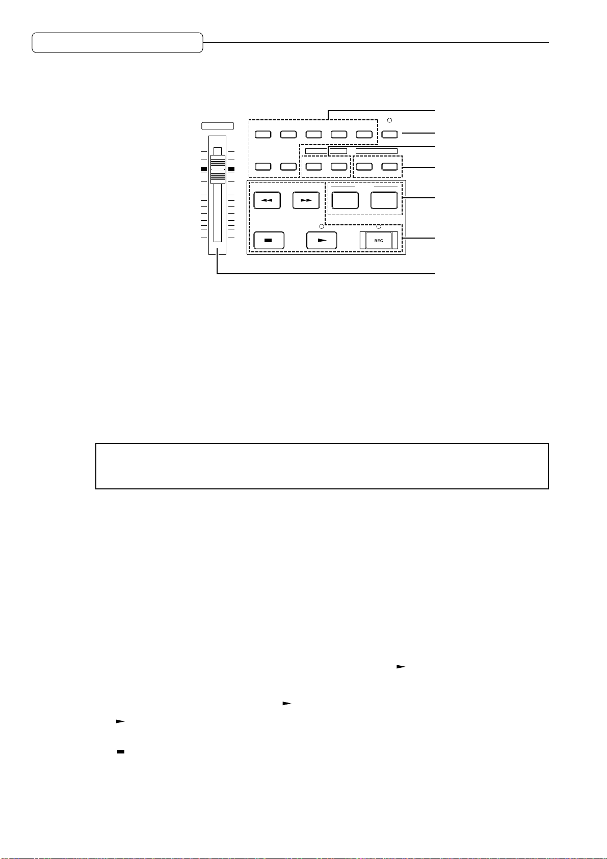
7 Channel faders
D
F2 F3 F4 F5
F6
JOG PLAY
NOPQR
SOLO
CANCEL
NUMBER/NAME
ENTER
mw
mt
mu
mv
These faders control the level of TRACK MIX channels.
8
Chapter 1: Outline of the DPS12
DIGITAL PERSONAL STU
9
F1
F2 F3 F4 F5
MNOPQR
F6
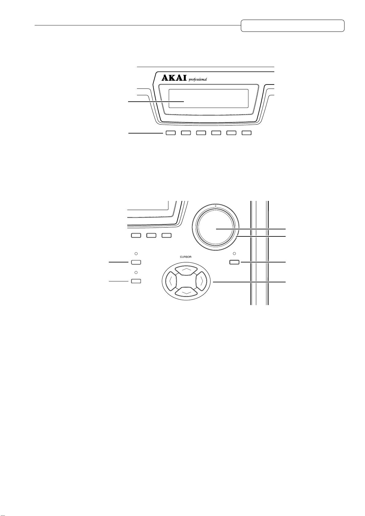
8 Display
This LCD display indicates various information required for operating the DPS12, such as the time
counter and level meter.
9 Function keys ([F1] – [F6])
These keys are used to execute or turn on/off the functions that appear on the bottom row of the
display.
mr
ms
mr [SOLO] ([CANCEL]) key
This key enables the Solo function in the mixer section. When this key is turned on, you can monitor the
tracks selected via the [RECORD SELECT] keys. It is also used as a [CANCEL] key to cancel the entry of
numeric values or characters.
ms [NUMBER/NAME] ([ENTER]) key
This key enables the input of numeric values and characters. When this key is turned on, the LED
above this key flashes, and you can enter the numbers, alphabets, and symbols, using the keys on the
top panel that have the corresponding labels below them. This key is also used as an [ENTER] key that
confirm the entry of the values and characters.
mt [JOG] dial
This dial is used to change the setting or value of an item selected by the cursor on the display . When
the [JOG PLA Y] key mv is turned on, you can perform jog-playback depending on the speed and direction
in which you rotate the dial.
mu [SHUTTLE] dial
This dial is used to select one digit of a time field value to be changed that was displayed via the [JOG]
dial. When the [JOG PLAY] key mv is turned on, you can perform shuttle-playback depending on the
angle and direction of this dial.
mv [JOG PLAY] key
This key enables jog-playback and shuttle playback. When this key is turned on, the waveform of a
selected channel appears on the display, and you can perform jog-playback via the [JOG] dial and
shuttle-playback via the [SHUTTLE] dial.
3
Chapter 1: Outline of the DPS12
mw [CURSOR] key
The cursor key is used to move the cursor (highlighted part) on the display to select an item to set.
MASTER
MAIN
MIXER
X
VIEW
EDIT
ASSIGN
T
S
IN
Z
Y
DISKUPROJECT
EDIT POINT PLAY
V
OUT&TO#FROM
LOCATE
GO TO
UNDO
SPACE
MEMORY
W
my
mz
m{
nr
TRACK
ns
nt
mx Mode keys ([MAIN] key / [TRACK VIEW] key / [ASSIGN] key / [DISK] key / [PROJECT] key /
[MIXER] key / [EDIT] key)
These keys are used to switch among various operating modes (MAIN mode, TRACK VIEW mode,
MIXER mode, etc.). The [MAIN], [TRACK VIEW], and [MIXER] keys are effective even during the recording
or playback operation, while the other keys are effective only when the operation is stopped.
my [UNDO] key
This key is used to cancel the recording or editing operation you just performed. When you press this
key right after you perform recording or editing, the previous status is restored and the LED above the
[UNDO] key lights up (Undo). Pressing the [UNDO] key again restores the status obtained when you
performed the recording or editing operation, and the LED turns off (Redo).
mx
✐
TIP :
The range of the Undo level parameter (to set how many previous operations can be
restored via the
[UNDO]
key) is 0 to 250. If the Undo level is set to “2” or higher, press the
[UNDO]
key, then enter the number of possible undo operations.
mz Edit point keys ([IN] key / [OUT] key)
These keys are used to store IN/OUT points that are used to specify the range for the Auto Punch In/
Out function and Edit function.
m{ Edit play keys ([TO] key / [FROM] key)
These keys are used for the Edit Play function that plays back data from or to the current stop position.
nr Locate keys ([MEMORY] key / [GO TO] key)
These keys are used to store the locate point (the position information in a song) and move the current
position on the DPS12 to any locate point.
ns Transport buttons
These keys are used to control the transport operation of the DPS12, such as recording, playback,
stop, etc. Each button has the following function:
• [REC] button............This button is used to record. Pressing the [ ] button while holding down the
[REC] button causes a track with its [RECORD SELECT] key on to enter recording
mode. Recording mode is also entered when you press the [REC] button while
holding down the [ ] button during playback (Punch In).
• [ ] button ............. This button is used to play back data. Pressing this button during recording
cancels recording, and playback continues (Punch Out).
• [ ] button ............. This button is used to stop recording, playback, fast forward, and rewind.
4
Chapter 1: Outline of the DPS12
• [ ] button ............ This button is used to rewind. Pressing this button while the transport section is
stopped causes the time counter on the display to count backward at high speed.
Pressing and holding down this button during playback causes fast reverse
playback for as long as you hold it down (Review).
• [ ] button............This button is used to fast forward. Pressing this button while the transport section
is stopped causes the time counter on the display to count forward at high speed.
Pressing and holding down this button during playback causes fast playback for
as long as you hold it down (Cue).
nt [MASTER] fader
This fader adjusts the master level of the mixer section.
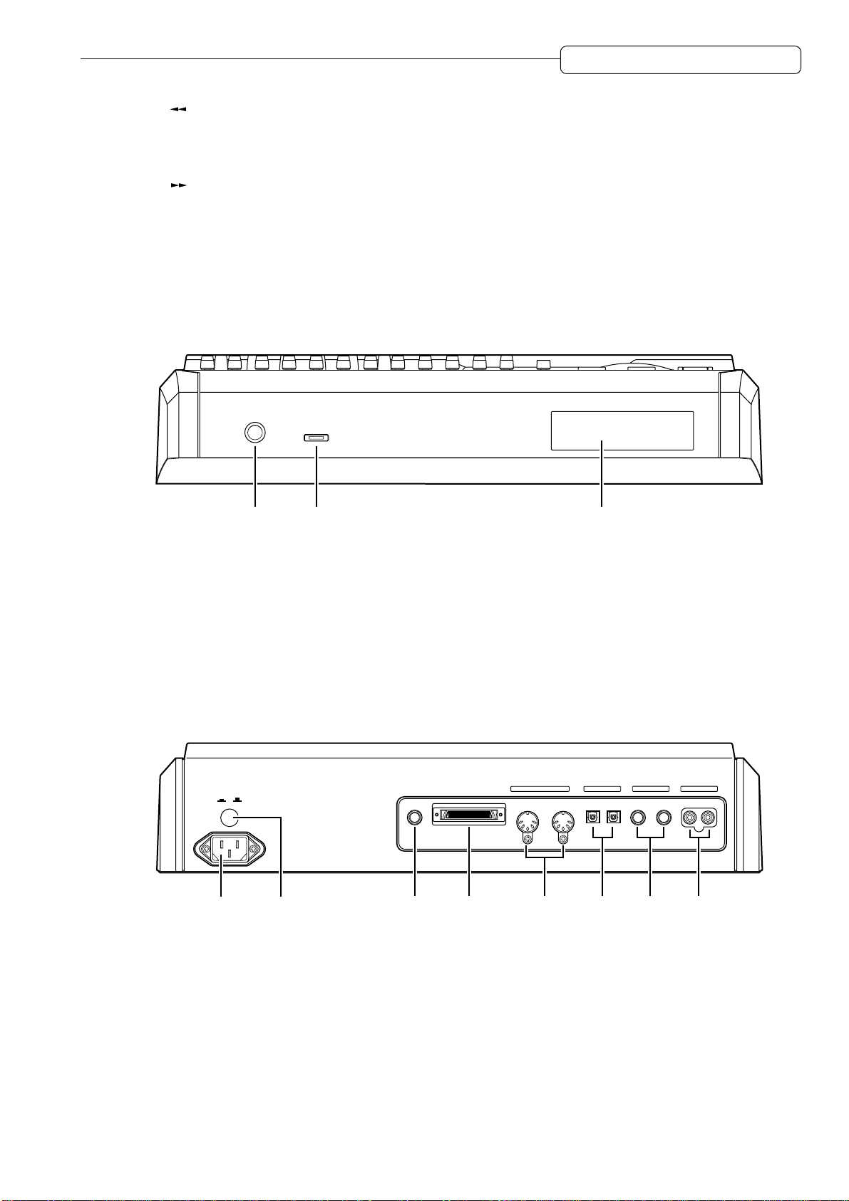
Front panel
PHONES
LEVEL
MAXMIN
1 2 3
1 PHONES (headphones) jack
Connect monitoring headphones to this jack, which outputs the same signal as that output from the
MASTER OUT jacks on the rear panel.
2 LEVEL (headphones level) control
This control adjusts the volume level of the headphones connected to the PHONES jack.
3 Internal drive
This is reserved for mounting internal Removable Media drive.
Rear panel
POWER
OFF
ON
FOOT SW. SCSI
MIDI
OUT/ THRU IN
OPTICAL AUX SEND MASTER OUT
OUT IN A B L R
87 65 4321
1 MASTER OUT L/R jacks
These jacks output a stereo signal that is a mix of each channel (TRACK MIX channels + THRU MIX
channels) of the mixer section.
2 AUX SEND (AUX send) A/B jacks
These jacks output a signal from each channel of the mixer section (TRACK MIX channels + THRU
MIX channels) to Send A/B. (If AUX TYPE is set to STEREO, a left signal and right signal will be output
from jack A and jack B respectively.)
5

Chapter 1: Outline of the DPS12
3 OPTICAL IN/OUT jacks
These jacks are used to transmit digital audio signals to and from a connected external digital device,
such as a DA T recorder. Depending on the settings, digital signals input from the OPTICAL IN jack are
sent to the tracks in the recorder section (physical tracks), or directly to the mixer section. The OPTICAL
OUT jack outputs the same signal as the digital signal output from the MASTER OUT jacks 1.
4 MIDI IN, OUT/THRU connectors
These connectors are used to transmit sync signals and control signals to and from a connected
external MIDI device, such as a MIDI sequencer.
5 SCSI connector
This connector is used to connect an external hard disk or MO drive.
6 FOOT SW. (foot switch) jack
This jack is used to connect a foot switch to control the Punch In/Out operation and playback/stop
operation with your foot.
7 POWER switch
This switch turns on/off the power to the DPS12.
8 Power connector
Connect the included power cable here.
Using a drive
If you have a drive installed on the DPS12, you can store audio data and other information on a disk. A
storage medium with a capacity of 1 GB can accommodate audio data of up to three hours sixteen minutes
(at a sampling rate of 44.1kHz in monaural).
Notes on using a drive
• To be able to use a disk on the DPS12, you need to format a disk first. (Refer to page 21, 110 for
information on how to format a disk.)
• If a disk is damaged for some reason, its data will be lost forever. We recommend that important data
be backed up to an external hard disk or an MO drive. (Refer to page 102 for information on backing up
data.)
6
Chapter 1: Outline of the DPS12
About external SCSI devices
The rear panel of the DPS12 is equipped with a half-pitch 50-pin SCSI connector (SCSI-2 standard),
which you can connect to an external hard disk or MO drive to back up, record, or play back data.
➸
NOTES :
• Some models of external SCSI devices may not be compatible with the DPS12. Also, you may not
be able to record or playback, or you may have only a limited number of tracks available for
simultaneous multitrack recording and playback.
• Consult AKAI professional technical support for more information on the manufacturers and models
of external SCSI devices that are compatible with the DPS12.
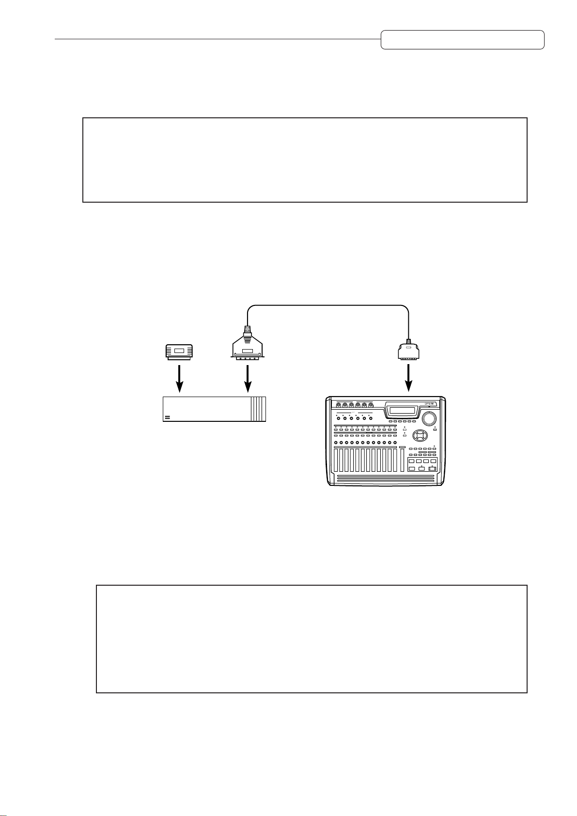
Connecting an external SCSI device
■ Connecting a single SCSI device
Use a SCSI cable to connect the DPS12 and one SCSI device.
SCSI cable
Terminator
SCSI connector
External hard disk
or MO drive
Example of connecting a single SCSI device to the DPS12
INPUT
INPUT GAIN
DPS12
dps12
Install a terminator on the SCSI device. If the SCSI device has a built-in active terminator, turn it on.
(Refer to the instruction manual that came with the SCSI device for more information on how to turn on
the active terminator.) Set the SCSI ID number of the external SCSI device to any number other than 4
or 6.
✐
TIPS :
• A terminator is a device that terminates the end of the SCSI connection. Usually, you install the
terminator on the SCSI device on the SCSI connector that is not connected to the SCSI cable.
Some SCSI devices may have a built-in active terminator that performs termination electrically.
In this case, turn the terminator on/off using the dedicated switch.
• SCSI devices recognize and identify each other using an identification of 0–7 called the SCSI ID.
The factory SCSI ID setting of the DPS12 is 6 (changeable), and the ID of the internal drive is 4
(fixed). You need to use other numbers as SCSI IDs for other connected SCSI devices.
7
Chapter 1: Outline of the DPS12
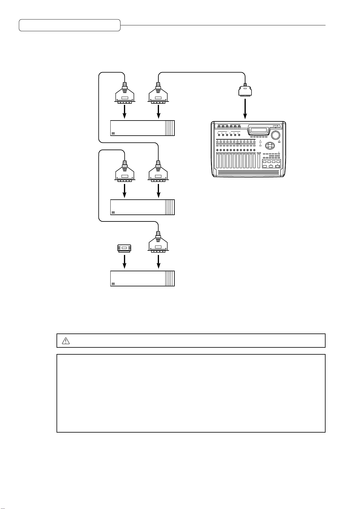
■ Connecting multiple SCSI devices
Use a daisy chain connection to connect multiple SCSI devices as shown below:
External hard disk
or MO drive
SCSI cable
To a SCSI
INPUT
INPUT GAIN
connector
dps12
DPS12
External hard disk
or MO drive
Terminator
External hard disk
or MO drive
Connecting multiple SCSI devices
Install a terminator on the last SCSI device in the daisy chain. (If the SCSI device has a built-in active
terminator, turn it on.) The default SCSI ID of the internal drive is set to 4 and the SCSI ID of the DPS12
is set to 6. Therefore, set the SCSI ID of all external SCSI devices to a number other than 4 or 6.
CAUTION :
➸
NOTES :
Turn off the power to all devices before performing SCSI connection.
• Use a short, high-quality SCSI cable, if possible. Using too long a cable or a low-quality cable
may cause an error.
• You need to format the disk before you can use the external hard disk or MO drive connected to
the DPS12. (Refer to page 21, 110 for more information on how to format the disk.)
• To record and play back data to the connected hard disk or MO drive, you need to specify the
drive as the current drive (currently selected drive). (Refer to page 108 for more information on
how to specify the current drive.)
• You cannot record one continuous stream of data to multiple disks.
8
Chapter 1: Outline of the DPS12
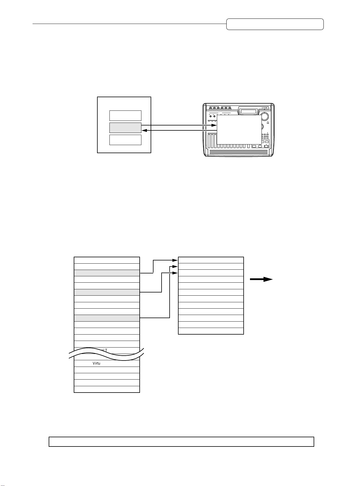
About Projects
The DPS12 manages songs by treating them as “Projects.” A Project contains audio data, mixer settings,
locate points (position information in a song), and scene memory (mix parameter settings).
The internal hard disk can store multiple Projects. However, the DPS12 can handle only one Project at a
time. When the power to the DPS12 is turned on, the DPS12 reads the first Project in the disk. You may
want to specify another Project on the disk to be read or create a new Project, if necessary.
DPS12
HARD Disk
Project
Project
Project
INPUT
INPUT GAIN
Reading
Project
Storing
dps12
About physical tracks and virtual tracks
The DPS12 performs recording and playback by assigning 250 virtual tracks to 12 physical tracks.
“Physical track” is a track that is used to record, play back, and edit in normal way . Physical tracks 1–12
correspond to the [RECORD SELECT] 1–12 keys on the top panel. Pressing any of these keys causes
the corresponding LED to flash and the corresponding track to enter recording standby mode.
“Virtual track” is used to store recorded audio data. Y ou cannot control virtual tracks. However , you can still
record, play back, and edit them by assigning them to physical tracks. The DPS12 provides 250 virtual
tracks, which you can assign to any of 12 physical tracks.
The following example shows Virtual tracks 3, 10, and 6 assigned to physical tracks 1, 2, and 3 respectively .
Virtual Track
Virtual Track 1
Virtual Track 2
Virtual Track 3
Virtual Track 4
Virtual Track 5
Virtual Track 6
Virtual Track 7
Virtual Track 8
Virtual Track 9
Virtual Track 10
Virtual Track 11
Virtual Track 12
Virtual Track 13
Virtual Track 14
Virtual Track 15
Virtual Track 16
Virtual Track 246
Virtual Track 247
Virtual Track 248
Virtual Track 249
Virtual Track 250
Physical Track
Track 1
Track 2
Track 3
Track 4
Track 5
Track 6
Track 7
Track 8
Track 9
Track 10
Track 11
Track 12
Mixer section
For example, you can switch virtual tracks that are assigned to recording tracks (physical tracks) to record
multiple takes of your solo performance. In this way, you can later select the best take for mixdown. You
can also store data in a virtual track to perform ping-pong recording onto the data repeatedly until you are
satisfied. Virtual tracks have various applications, and you can use the DPS12 without being limited to
twelve tracks.
✐
TIP :
You can also name virtual tracks.
9
Chapter 1: Outline of the DPS12
TRACK MIX channels and THRU MIX channels
The DPS12’s mixer section offers eight channels (called “THRU MIX channels”) that enable you to control
input signals that come directly from the INPUT jacks, as well as twelve channels (called “TRACK MIX
channels”) that you can control for panning and level from the top panel.
Normally, you can record and mix down audio data using only the TRACK MIX channels. However, the
THRU MIX channels are useful when you wish to overdub external sound sources while playing back
twelve tracks in the recorder section.
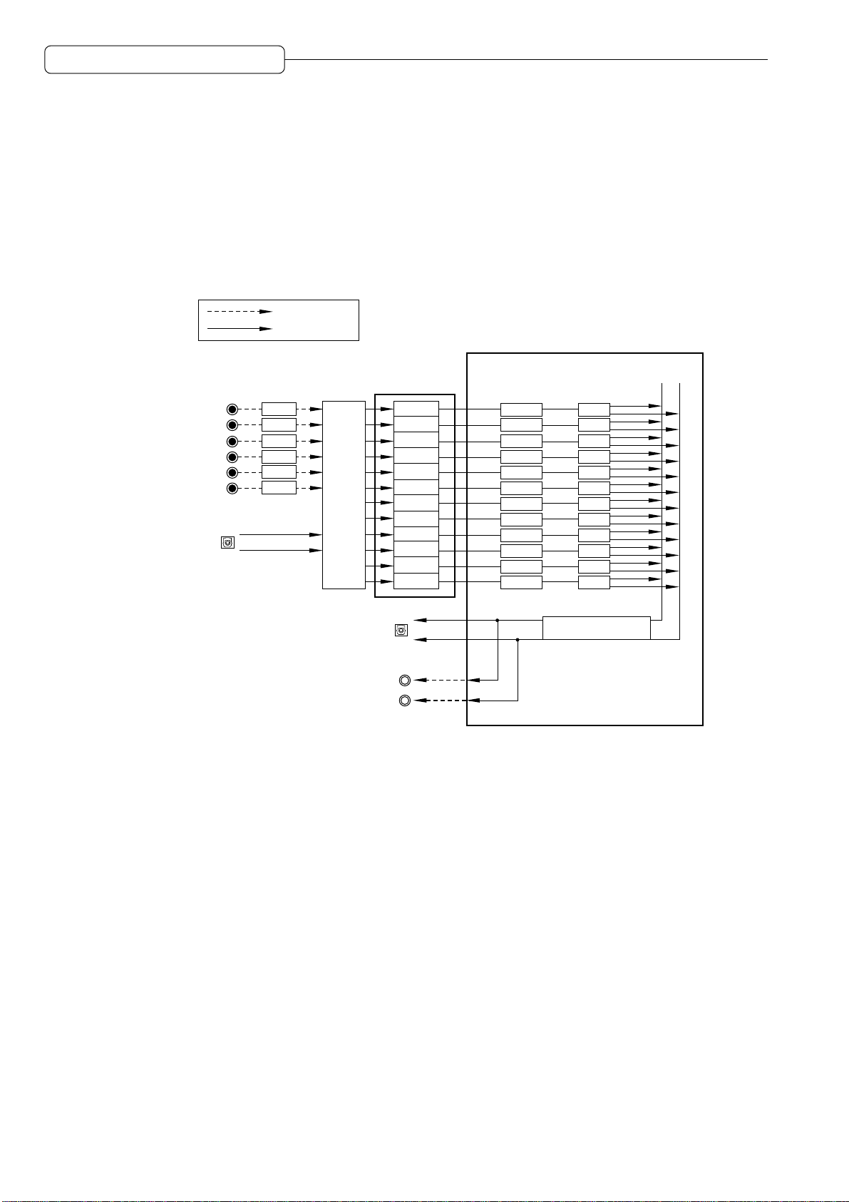
The following diagram shows a basic signal flow. When the DPS12 is in default status, use the TRACK
MIX channels to record and mix down data.
Analog signal
Digital signal
Mixer section
INPUT
(ANALOG)
1
2
3
4
5
6
OPTICAL IN
(DIGITAL)
Recorder
section
GAIN
GAIN
GAIN
GAIN
GAIN
GAIN
Input
Assign
OPTICAL OUT
(DIGITAL)
MASTER OUT
(ANALOG)
A typical signal flow when only TRACK MIX channels are used
Tr1
Tr2
Tr3
Tr4
Tr5
Tr6
Tr7
Tr8
Tr9
Tr10
Tr11
Tr12
L
R
TRACK MIX channel
1
LEVEL
2
LEVEL
3
LEVEL
4
LEVEL
5
LEVEL
6
LEVEL
7
LEVEL
8
LEVEL
9
LEVEL
10
LEVEL
11
LEVEL
12
LEVEL
LR
PAN
PAN
PAN
PAN
PAN
PAN
PAN
PAN
PAN
PAN
PAN
PAN
MASTER LEVEL
10
• Signals input from the INPUT jacks (analog/digital) are adjusted for the gain via the GAIN controls, then
routed to the Input Assign section and assigned to each physical track. (T rack assignment is performed
in Assign mode. See page 52 for more information.)
• Physical tracks 1–12 of the recorder section are directly routed to TRACK MIX channels 1–12 of the
mixer section. Usually , input signals routed from the INPUT jacks are sent from recording-ready tracks
to the mixer section, and the recorder playback signals are sent from other tracks to the mixer section.
• You can set the level and pan of the signals sent to the TRACK MIX channels, using the faders and the
PAN controls on the top panel before mixing down to a stereo signal. You can also adjust the mixrelated parameters, such as channel on/off, EQ, and AUX send A/B. (These settings are available in
Mixer mode. Refer to page 58 for more information.)
• The master level of the stereo mix signal is adjusted by the master fader on the top panel. This signal
is output from the MASTER OUT jacks (analog) and the OPTICAL OUT jacks (digital).
Y ou can also send the input signals at the INPUT jacks directly to the mixer section, instead of sending
them to the recorder section. In this case, you can use the THRU MIX channels. The following diagram
shows a typical signal flow when the THRU MIX channels are used.
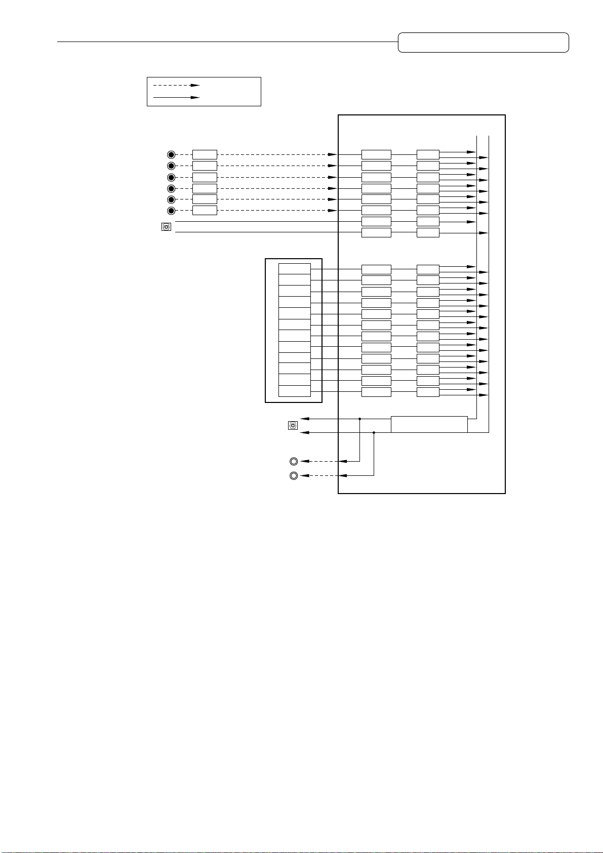
Analog signal
Digital signal
Chapter 1: Outline of the DPS12
Mixer section
INPUT
(ANALOG)
1
2
3
4
5
6
OPTICAL IN
(DIGITAL)
GAIN
GAIN
GAIN
GAIN
GAIN
GAIN
OPTICAL OUT
(DIGITAL)
Recorder
section
Tr1
Tr2
Tr3
Tr4
Tr5
Tr6
Tr7
Tr8
Tr9
Tr10
Tr11
Tr12
THRU MIX channel
1
LEVEL
2
LEVEL
3
LEVEL
4
LEVEL
5
LEVEL
6
LEVEL
DL
LEVEL
DR
LEVEL
TRACK MIX channel
1
LEVEL
2
LEVEL
3
LEVEL
4
LEVEL
5
LEVEL
6
LEVEL
7
LEVEL
8
LEVEL
9
LEVEL
10
LEVEL
11
LEVEL
12
LEVEL
LR
PAN
PAN
PAN
PAN
PAN
PAN
PAN
PAN
PAN
PAN
PAN
PAN
PAN
PAN
PAN
PAN
PAN
PAN
PAN
PAN
MASTER LEVEL
MASTER OUT
(ANALOG)
A typical signal flow when both TRACK MIX channels and THRU MIX channels are used
L
R
• You can route each input signal to a THRU MIX channel or to the recorder section individually. In this
example, all input signals are sent to the THRU MIX channels. (This routing is done in Assign mode.
Refer to page 52 for more information.)
• You can also set the mix-related parameters, such as the level, pan, channel on/off, EQ, and AUX send
A/B, for the signals sent to the THRU MIX channels, as well as the signals sent to the TRACK MIX
channels. Use Mixer mode to set the mix parameters for the THRU MIX channels. You cannot control
the level and pan from the top panel. (Refer to page 58 for more information on Mixer mode.)
• The stereo mix signal of the THRU MIX channels and TRACK MIX channels is adjusted for the master
level by the master fader on the top panel, then output from the MASTER OUT jacks (analog) and the
OPTICAL OUT jacks (digital).
• You can use two-channel (A/B) internal effects in the digital domain if you have an optional effects
board EB2M installed. In this case, each channel’s AUX send A/B functions as an effect send. The
return signal from the internal effects can be routed to the tracks for recording, or routed directly to the
mixer section via the THRU MIX channels.
11
Chapter 1: Outline of the DPS12
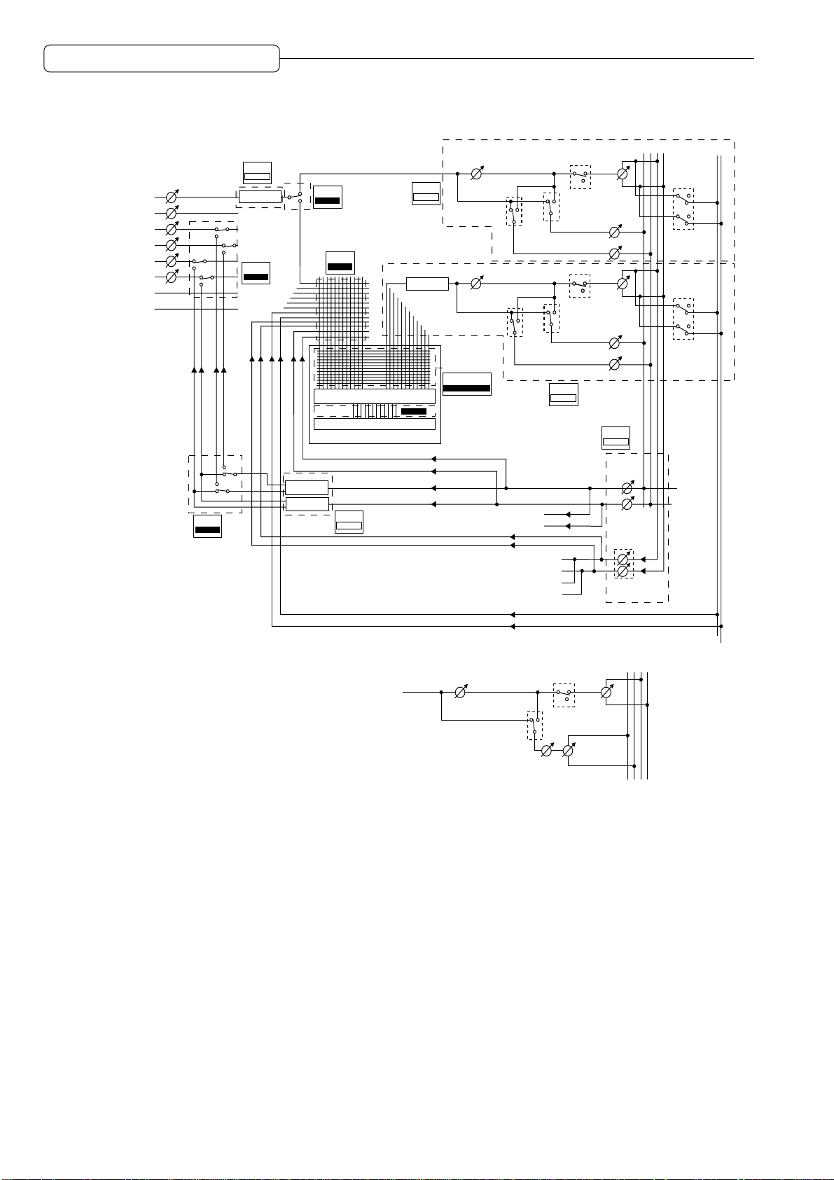
INPUT 1 (analog)
INPUT 2 (analog)
INPUT 3 (analog)
INPUT 4 (analog)
INPUT 5 (analog)
INPUT 6 (analog)
INPUT L (digital)
INPUT R (digital)
INPUT
GAIN
ASSIGN
FX RTN
MIXER
THRU
THRU EQ
ASSIGN
FX RTN
MULTI
MULTI
ASSIGN
THRU
ASSIGN
SOURCE
ASSIGN
REC
PHYSICAL TRACK
VIRTUAL TRACK
HARD DISK
MIXER
EFFECT
MIXER
THRU
TRACK EQ
PLAY
V.TRK
LEVEL
SEND B
PRE/POST
LEVEL 1-12
SEND B
PRE/POST
PLAY MONITOR
MAIN
CONTROL PANEL
AUX SEND A
AUX SEND B
SEND A
PRE/POST
SEND A
PRE/POST
MIXER
TRACK
SOLO
SOLO
SEND A
LEVEL
SEND B
LEVEL
SEND A
LEVEL
SEND B
LEVEL
PAN
PAN
1-12
MIXER
THRU
SEND-A
MASTER
SEND-B
MASTER
ABLR
Extra BUS
LR
Extra BUS
Extra BUS
AUX mode is set to stereo.
*
THRU signal
LEVEL
or
TRACK playback signal
Signal block diagram
MASTER OUT L (analog)
MASTER OUT R (analog)
DIGITAL OUT L (digital)
DIGITAL OUT R (digital)
SOLO
AUX SEND
PRE/POST
SEND
LEVEL
SEND
PAN
PAN
MASTER
LEVEL
ABLR
12
Chapter 1: Outline of the DPS12
About a scene memory
The DPS12 can store a set of mix parameter settings as a scene, and recall the scene later. A scene is
stored as part of the Project in the disk. You can store multiple scenes in one Project. For example, you
may store multiple scenes with different balance and EQ settings for mixdown, and audition and compare
different mixes.
The following main parameters are stored in a scene.
• Channel level/master level settings (See page 61.)
• Channel panning (See page 61.)
• Channel AUX send A/B settings (send level, pre/post selection) (See page 64.)
• Channel EQ setting (See page 62.)
About DPS12’s user interface
This section explains the basic operation of the DPS12, such as using the display and changing the
values.
Using the display
V arious information required for operating the DPS12, such as the current position, mix parameter settings,
etc., appears on the display . The information varies depending on which key you operate (such as a mode
key, edit point key, locate key, etc.).
■ Screen
A display that appears when you press a mode key is called “screen.” For example, the following
display is a MAIN screen that is recalled when you turn on the power to the DPS12 or when you press
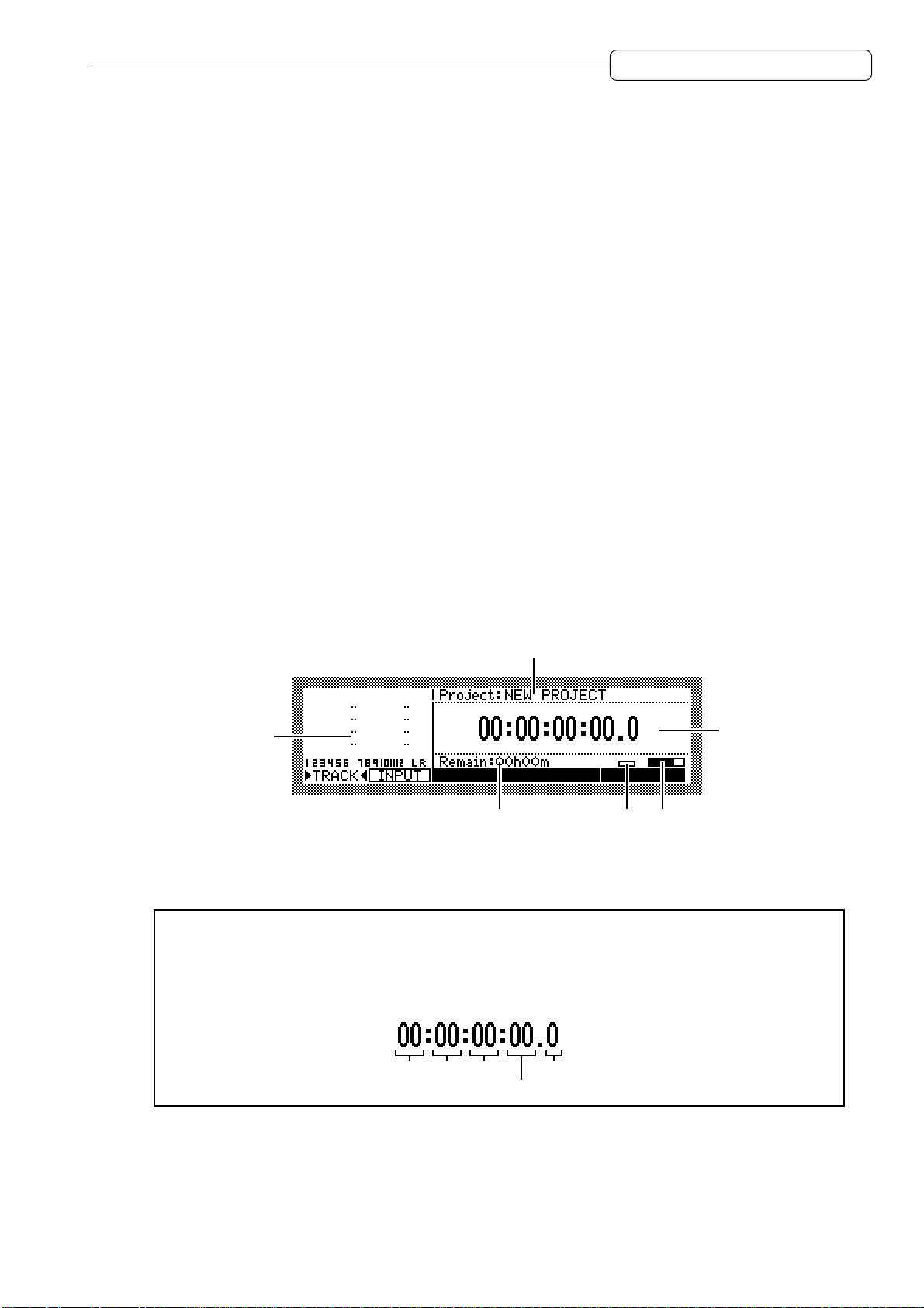
the [MAIN] key. You will use this screen for recording and playback.
MAIN screen
3
CONTROL@PANEL
2
1
CD-R
465
The MAIN screen shows the following information:
1 Time counter............ Indicates the current transport position. Y ou can enter a value into the time counter
to move to a desired position.
✐
TIP :
The DPS12 displays the time counter using hour, minute, second, frame, and sub-frame
unit. The term “frame” is borrowed here from the world of motion picture film and video, in which
each still image from the sequence of images that appear or a strip of film is called a “frame.”You
can change the number of frames in the Control Panel (page 91). A sub-frame is a unit obtained
by dividing a frame by ten.
hour minute second
2 Level meter.............. Indicates the output level of the physical tracks, the input level at the INPUT
jacks, or the output level of the AUX send A/B or the master output.
3 Project name ........... Indicates the name of the Project you are currently working on.
sub-frame
frame
13
Chapter 1: Outline of the DPS12
4 Remaining time ....... Indicates the remaining time available for recording on the disk.
5 Busy meter ..............This meter indicates that the disk is being accessed. The more the meter is
6
Disc access indicator ...
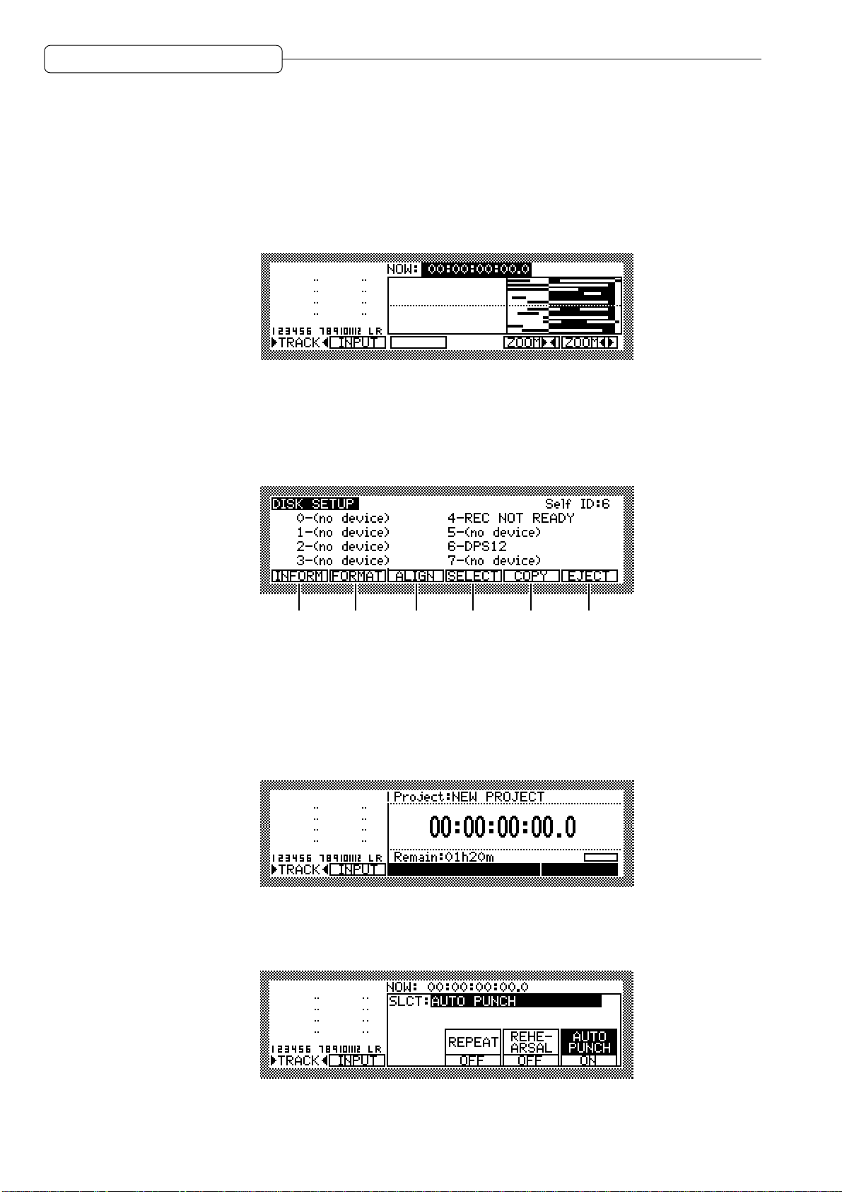
Pressing any mode key other than the [MAIN] key in the MAIN screen will show the screen of the
corresponding mode. For example, pressing the [TRACK VIEW] key will switch to Track View mode
and the TRACK VIEW screen will appear.
The TRACK VIEW screen indicates the length of recorded data for each physical track in a bar graph.
Remember that depending on which mode key you press, the screen will change.
■ Function key display
Sometimes, function names appear on the bottom of the screen as shown below. These are the functions that correspond to function keys ([F1] key – [F6] key).
moves, the more frequently the disk is being accessed.
This indicator lights up when the disk is being accessed.
CTRL.P
[F1] [F2] [F3] [F4] [F5]
[F6]
Function keys are special keys in that each of them does not have a single fixed function, but has
different functions depending on the screen currently shown in the display. For example, pressing the
[F2] key in the DISK SETUP screen as shown above will execute the disk format function.
■ Control panel
Pressing one of the [F3] – [F5] keys in the MAIN screen will switch the screen to the Control Panel
screen as shown below.
MAIN screen
CD-RCONTROL@PANEL
↓
Press one of [F3] – [F5] keys.
↓
Control Panel
14
The Control Panel screen is used to set various parameters on the DPS12. Pressing a mode key after
the setting is complete will take you to the corresponding mode screen.
Chapter 1: Outline of the DPS12
■ Field and cursor
The parameter values that are shown on the display and that can be modified are called “fields.” The
highlighted part of the screen is called the “cursor.” The field currently highlighted by the cursor indicates
that the field is selected for editing. If there are multiple fields in a screen, use the [CURSOR] key to
move the cursor to the desired field.
CURSOR
Fields are categorized as follows:
• Select field
This type of field offers options you choose from.
• Numeric field
In this type of field, you can change the parameter value.
CURSOR
• Time field
In this type of field, you can change the time on the counter and the locate point.
• Character field
This type of field is used to name the locate point, virtual tracks, and Projects.
• Graphic field
This type of field indicates the mix parameter settings graphically.
15
Chapter 1: Outline of the DPS12
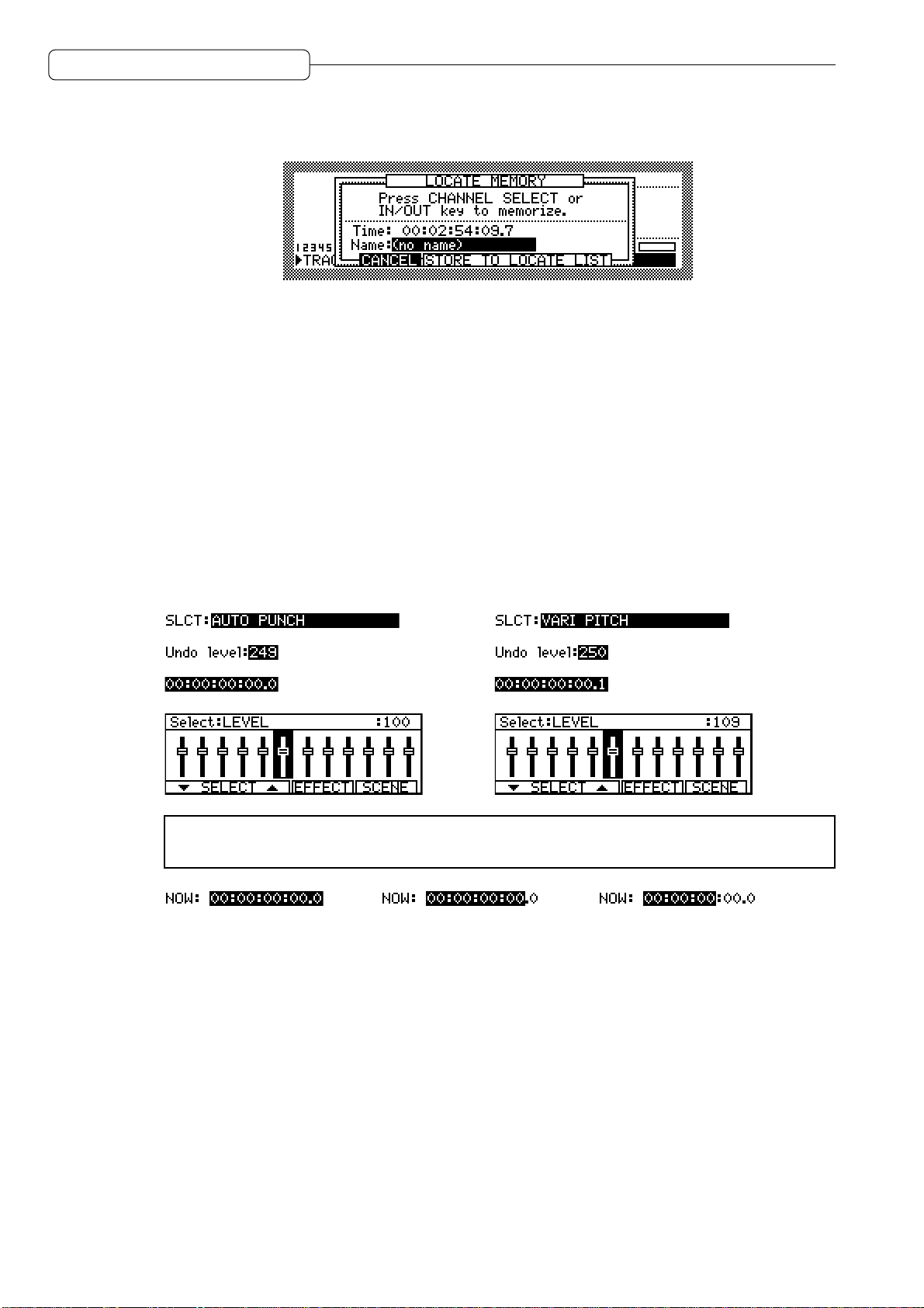
■ Window
When you press the [UNDO] key, [GO TO] key, or [MEMORY] key, a window appears on the screen.
A window is used to make a setting or operate a function that varies depending on the key you pressed.
As you do in a normal screen, you can change the parameter settings by moving the cursor to the
desired parameter, or use the function keys to execute the desired function. After the function or operation
is complete, the previous screen will be restored.
Changing a setting or a value
This section describes how to change the time on the counter, and the settings and values of the fields.
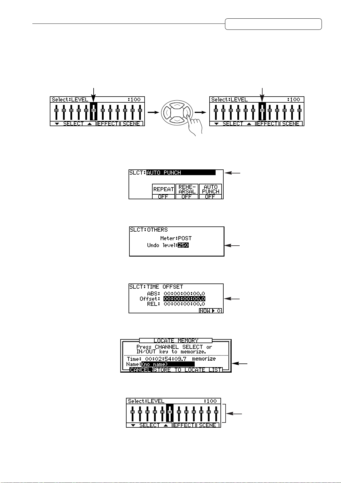
■ Using the [JOG] dial to change the setting (select field/numeric field/time field/graphic
field)
Use the JOG dial to edit the parameter settings of the select fields, numeric fields, time fields, and
graphic fields.
1. Use the [CUROSOR] key to move the cursor to the field you wish to edit.
2. Rotate the [JOG] dial to change the setting.
→
→
→
→
✐
TIP :
the
[SHUTTLE]
Use the
[SHUTTLE]
dial to select a digit to change, then use the
dial to select a digit to edit when a time field is selected. First rotate
→ →
[JOG]
dial to change the value.
16
Chapter 1: Outline of the DPS12
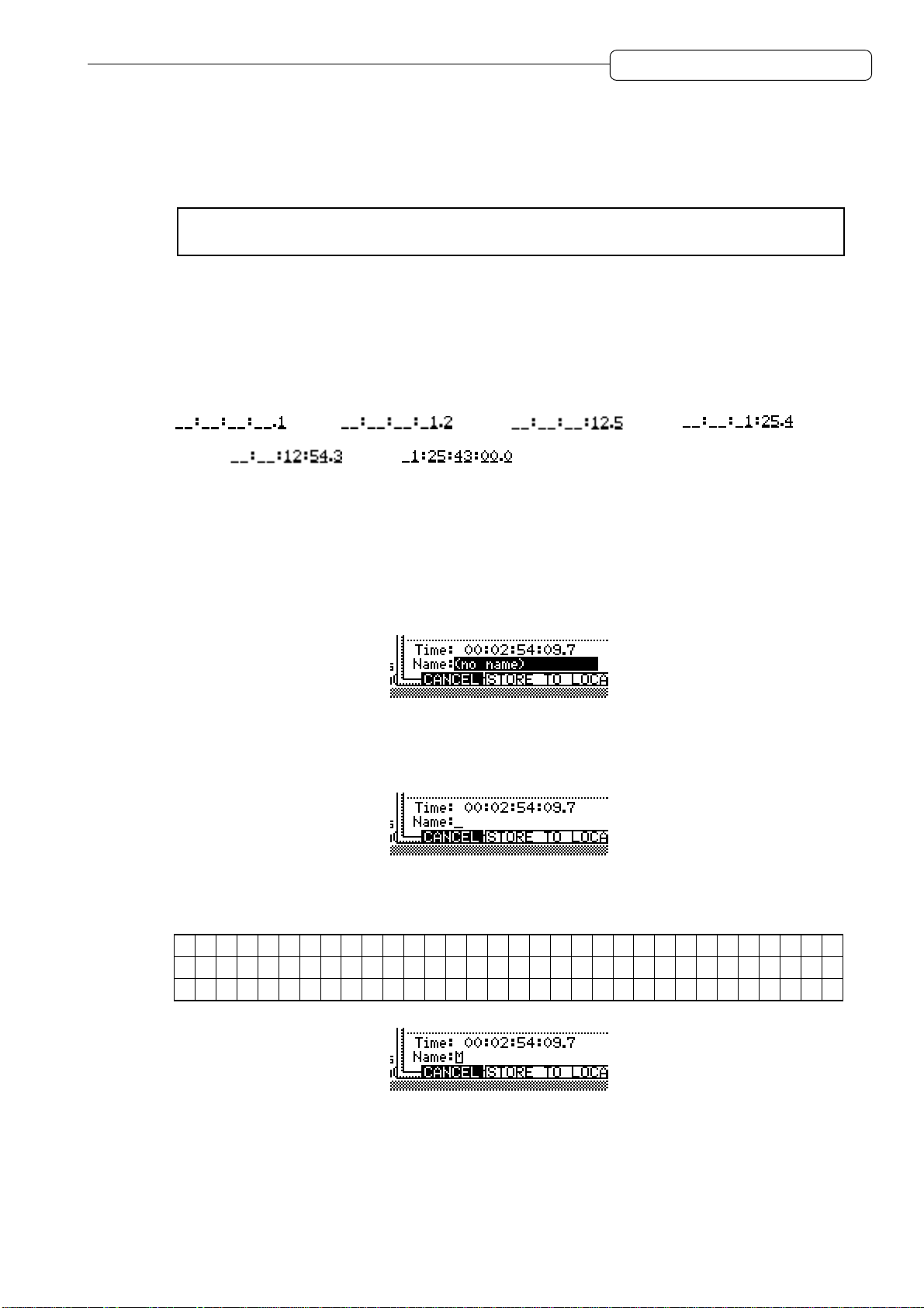
■ Entering a numeric value directly (time counter/time field)
You can use the keys on the top panel to directly enter a value for the time counter, and time field on
the MAIN screen. Follow the steps below:
1. Use the [CURSOR] key to move the cursor to a time field.
➸
NOTE :
screen.
2. Press the [NUMBER/NAME] key.
The [NUMBER/NAME] key’s LED flashes, and the keys on the top panel function as numeric keys.
3. Use the [CHANNEL SELECT] 1–10 keys to enter a desired number (1–9, 0).
The [CHANNEL SELECT] 1–10 keys function as numeric keys 1–9, 0.
For example, if you wish to enter 1 hour 25 minutes 43 seconds for the time counter or a time
field, press the [CHANNEL SELECT] 1–10 keys in the following order:
→ →
4. Press the [NUMBER/NAME] key again.
This time, the [NUMBER/NAME] key functions as an [ENTER] key. The [NUMBER/NAME] key’s LED
turns off, and the entered number is confirmed. If you wish to cancel the entered number , press the
[SOLO] key (which functions as a [CANCEL] key) to go back to the previous display.
You do not need this step when you enter the time for the time counter in the MAIN
→ → →
■ Using the [JOG] dial to enter characters (character field)
1. Use the [CURSOR] key to move the cursor to a character field.
2. Press the [NUMBER/NAME] key.
The [NUMBER/NAME] key’s LED flashes and an underline appears under the first character in the
character field. This underline indicates that you can enter a character.
3. Rotate the [JOG] dial to select a character to enter.
The following numbers, letters, and symbols can be selected by the [JOG] dial.
A B C D E F G H I J K L M N O P Q R S T U V W X Y Z [ ¥ ] ^ _
a
b c d e f g h i j k l m n o p q r s t u v w x y z { | } ¯
"
# $ % & ' ( ) * + , - . / 0 1 2 3 4 5 6 7 8 9 : ; < = > ? @
¬
X !
17
Chapter 1: Outline of the DPS12
4. Use the [CURSOR] key or the [SHUTTLE] dial to move the underline to the second character
position.
While the [NUMBER/NAME] key’s LED is flashing, you can move the underline back and forth using
the [CURSOR] key or the [SHUTTLE] dial.
5. Repeat Steps 3 and 4 to complete naming.
If you enter a wrong character, use the [CURSOR] key or the [SHUTTLE] dial to move the underline
to the character you wish to correct.
6. Press the [NUMBER/NAME] key again.
This time, the [NUMBER/NAME] key functions as an [ENTER] key. The [NUMBER/NAME] key’s LED
turns off, and the entered characters are confirmed. If you wish to cancel the entered character,
press the [SOLO] key (which functions as a [CANCEL] key) to return to the previous display.
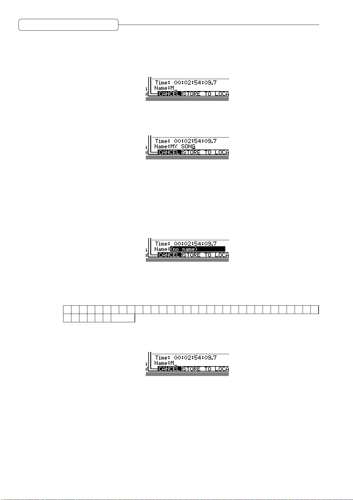
■ Entering characters directly (character field)
You can enter characters directly into a character field by using the keys on the top panel.
1. Use the [CURSOR] key to move the cursor to a character field.
2. Press the [NUMBER/NAME] key.
The [NUMBER/NAME] key’s LED flashes, and the keys on the top panel function as number/letter
keys. Alphabets, numbers, and symbols are printed below the keys. The following characters can
be entered.
1 2 3 4 5 6 7 8 9 0 A B C D E F G H I J K L M N O P Q R S T U
W
X Y Z & # (Space)
3. Press the key that corresponds to an alphabet, number, or symbol you wish to enter.
The character that corresponds to the pressed key is entered and the underline moves to the right.
V
18
4. Repeat Step 3 repeatedly to complete naming.
5. Press the [NUMBER/NAME] key again.
This time, the [NUMBER/NAME] key functions as an [ENTER] key. The [NUMBER/NAME] key’s LED
turns off, and the entered characters are confirmed. If you wish to cancel the entered character,
press the [SOLO] key (which functions as a [CANCEL] key) to return to the previous display.

Chapter 2: Recording on the DPS12
INPUT
DIGITAL PERSONAL STUDIO
dps12
INPUT GAIN
Master recorder
(DAT recorder/MD recorder)
DIGITAL
IN
DIGITAL
OUT
DIGITAL OUT
OPTICAL
OUT
AUX SEND A/B
OPTICAL
IN
MASTER
OUT
LINE IN
External effect processor
DPS12
Sampler
Monitor system
PHONES
Headphones
Dynamic microphone
Synthesizer/rhythm machine
Effect processor,
direct box, pre-amp, etc.
Chapter 2: Recording on the DPS12
This chapter describes basic operations of the DPS12, including recording preparation, recording the
first part, overdubbing, mixdown to a master recorder.
Connections
The diagram below is an example of basic connections for recording on the DPS12.
CAUTION :
Make sure that you turn off the power to all equipment before making connections.
➸
NOTE :
DIGITAL OUT jacks on AKAI sampler are of the coaxial type. You will need an optical
converter to connect a sampler to input digital signals to the DPS12.
19

Chapter 2: Recording on the DPS12
■ Connecting sound sources
You can connect line-level instruments, such as a synthesizer or a rhythm machine, and dynamic
microphones directly to INPUT jacks 1–6. We recommend that you connect instruments with a high
output impedance, such as an electric guitar or a bass guitar, via a compact effect processor, pre-amp,
or direct box.
■ Connecting a monitor system
Connect a monitor system, such as audio equipment, to the MASTER OUT jacks. If you are using the
DPS12 with a master recorder connected all the time, connect the output jacks of the master recorder
to the monitor system.
■ Connecting a master recorder
If you use a master recorder that has digital input jacks, such as a DAT recorder or an MD recorder,
connect the OPTICAL OUT jacks of the DPS12 to the digital input jacks of the master recorder , and the
output jacks of the master recorder to the monitor system.
✐
TIP :
If the digital I/O jacks of the master recorder are coaxial, you will need an optical/coaxial
converter.
Similarly , if you use an analog recorder as the master recorder , connect the MASTER OUT jacks of the
DPS12 to the input jacks of the master recorder, and the output jacks of the master recorder to the
monitor system.
In either case, switch the master recorder to input monitoring status (monitoring the input signal) in
order to record or play back on the DPS12, and switch the recorder to tape monitoring status (monitoring
the playback sound) in order to play back the master recorder.
■ Connecting a device that has digital output jacks
To input signals from a device that has digital output jacks, such as a DAT recorder, MD recorder,
sampler, etc., into the DPS12, connect the digital output jacks of the external device to the OPTICAL IN
jacks of the DPS12.
➸
NOTE :
digital device matches that of the DPS12. (See page 75.)
When you connect digital inputs, make sure that the sampling rate of the connected
■ Connecting an external effect unit
To use external effects, such as reverb and delay, connect the AUX SEND A/B jacks of the DPS12 to
the input jacks of the external effect unit, and the output jacks of the effect units to the INPUT jacks of
the DPS12.
20

Chapter 2: Recording on the DPS12
Preparing to record
This section explains the necessary preparations for recording.
Turning on the power to the DPS12
1. Turn on the power to the peripheral devices, excluding the DPS12 and the monitor system.
The sequence for turning on the power to each device is: peripheral devices (such as tone generator,
external SCSI device) DPS12 monitor system.
Reverse this order when you turn off the power.
2. Turn on the power to the DPS12.
When you turn on the power to the DPS12, the following initial screen appears.
3. Press the
The following screen (called the MAIN screen) appears on the display.
4. Turn on the power to the monitor system.
SKIPSKIP
SKIP [F6] key.
SKIPSKIP
CD-RCONTROL@PANEL
Formatting a disk
Before you can use a disk on the DPS12, you first need to format the disk. Follow the procedure below to
format a disk. (Ignore this procedure if you use a pre-formatted disk.)
1. Press the [DISK] key.
The display changes as follows:
This is a DISK SETUP screen where you can make settings for the internal drive or an external hard
disk. In this example, the screen shows the status of connected drives with SCSI ID numbers 0–7. The
SCSI ID of the internal drive is 4, and that of the DPS12 is 6. Also, this DISK SETUP screen displays six
functions on the bottom line, which you can recall using the [F1] – [F6] keys.
21

Chapter 2: Recording on the DPS12
2. Use the [CURSOR] key to move the cursor to the select field for SCSI ID 4, and press the
FORMATFORMAT
FORMAT [F2] key.
FORMATFORMAT
The following window appears.
3. Rotate the [JOG] dial to select
operationoperation
operation.
operationoperation
CAUTION :
When you perform the format operation, all existing data on the disk will be erased.
FORMATFORMAT
FORMAT for the select field that currently indicates
FORMATFORMAT
FormatFormat
Format
FormatFormat
If an external SCSI device, such as a hard disk or an MO drive is connected to the SCSI connector
of the DPS12, make sure that the SCSI ID field in this screen is set to “4” (internal drive) so that you
will not erase important data from other disks.
4. Press the
DO ITDO IT
DO IT [F5] key.
DO ITDO IT
The CAUTION!! window appears, asking whether you are sure you want to format the disk.
5. Press the
DO ITDO IT
DO IT [F5] key again.
DO ITDO IT
The following window appears during the format operation.
✐
TIPS :
• To cancel the format operation and go back to the DISK SETUP screen in Step4, 5, press the
CANCELCANCEL
CANCEL
CANCELCANCEL
[F2]
key instead of the
DO ITDO IT
DO IT
DO ITDO IT
[F5]
key.
• If you use an external SCSI device, such as a hard disk or an MO drive, you need to format it.
Select the SCSI ID for the corresponding external SCSI device in Step 3, then continue with the
procedure.
22

Chapter 2: Recording on the DPS12
Creating a new Project
Since the DPS12 requires that at least one project exists on the current disk for recording, the following
window for creating a new Project automatically appears when the format operation is complete.
Project nameProject name
The
Project name field indicates the name of the Project you are creating.
Project nameProject name
1. Press the [NUMBER/NAME] key.
An underline appears as follows, enabling you to name a new Project.
2. Use the [JOG] dial, or alphabet keys and the [CURSOR] key, or the [SHUTTLE] dial to enter
characters.
✐
TIP :
Refer to page 17, 18 for information on how to enter characters.
3. Press the [NUMBER/NAME] ([ENTER]) key to confirm the name.
➸
NOTE :
If you do not press the
[NUMBER/NAME] ([ENTER]
) key, the changed name will not
be confirmed.
4. Press the
DO ITDO IT
DO IT [F5] key.
DO ITDO IT
The DPS12 creates a new Project with a new name, and the display returns to the MAIN screen.
23

Chapter 2: Recording on the DPS12
MAIN screen and TRACK VIEW screen
The MAIN screen or TRACK VIEW screen can be useful when you are recording or playing back on the
DPS12. (Y ou can use the transport function and the locate function on either screen.) This section explains
how to use the MAIN screen and TRACK VIEW screen.
MAIN screen
The MAIN screen is a start point for various operations on the DPS12. When you turn on the power to the
DPS12, this screen always appears if a formatted disk (that contains a Project) is in the disk slot. The
following information is included in the MAIN screen.
5
1
CONTROL
2
@
PANEL
CD-R
4
3
6
1 Time counter
The time counter indicates the current recording or playback time. Y ou can also enter a time value here
to move to the desired position. (See page 47.)
2 Remaining time
This field indicates a remaining time available for recording on the disk (or a connected external hard
disk). If some tracks have been selected by the [RECORD SELECT] keys, this field indicates the total of
available recording time on those tracks. If all [RECORD SELECT] keys are turned off, this field indicates
available recording time for a single track.
3 Busy meter
This meter indicates that the disk (or the connected external hard disk) is being accessed. The more
the meter is moving, the more frequently the disk is being accessed.
4 Disc access indicator
This indicator lights up when the disk is being accessed.
CAUTION :
Otherwise, the disk or connected external hard disk may be damaged, and the data may be lost
forever.
5 Level meter
The level meters indicate input levels and output levels. The meters have two different functions: TRACK
level meter and INPUT level meter. These functions are switched via the
key. ( mark appears on the selected function’s name.)
Do not turn off the power to the DPS12 while the disk is being accessed.
TRACKTRACK
TRACK [F1] key/
TRACKTRACK
INPUTINPUT
INPUT [F2]
INPUTINPUT
24
Level meters when INPUT is selected
Maximum (clipping)
CD-RCONTROL@PANEL
• 1–6 ..........................Input level of analog INPUT jacks 1–6
• DLR ......................... Input level of digital OPTICAL IN jacks L/R
• SAB ......................... Output level of AUX send A/B
• LR ............................Output level of master L/R

Chapter 2: Recording on the DPS12
Level meters when TRACK is selected
Maximum (clipping)
Already recorded tracks
CD-RCONTROL@PANEL
11
•
•
1212
1 –
12 .................. Output level of tracks 1–12
11
1212
LRLR
LR ........................ Output level of master L/R
LRLR
6 Function display
The names of the functions appear on the bottom of the screen. The [F1] key/[F2] key are used to
switching the INPUT level meters/TRACK level meters, and the [F3] key – [F5] key are used to recall the
Control Panel. The [F6] key is used to setup CD-R/RW drive related parameters.
TRACK VIEW screen
Pressing the [TRACK VIEW] key while the MAIN screen is displayed will cause the DPS12 to enter TRACK
VIEW mode, and the TRACK VIEW screen will appear . In this screen, data in each track is represented by
a bar graph, if any, and the range between the IN point and the OUT point (used to specify the range for
the Auto Punch In/Out operation or the edit functions) is highlighted. This screen is useful when you mark
the Auto Punch In/Out points or specify the range for editing.
13
4
5
CTRL.P
2
6
NOW:NOW:
1
NOW: field
NOW:NOW:
This time field indicates the current position. You can also enter the time directly.
2 Bar graph
If a track contains data, it is represented by a bar graph. Any recorded area (even if it is a silence) is
represented by a bar graph.
3 IN point/OUT point range
The range between the IN point and the OUT point is highlighted.
4 Level meters
These are the same level meters as those that appear in the MAIN screen.
5 Function display
The names of the functions appear on the bottom of the screen. The [F1] key and [F2] key are used to
switch between the INPUT level meters and TRACK level meters, and the [F5] key and the [F6] key are
used to zoom in and out on the bar graphs. The [F3] key accesses to the Control Panel screen directly .
6 Now point
This vertical line indicates the position currently shown in the
NOWNOW
NOW field.
NOWNOW
25

Chapter 2: Recording on the DPS12
Recording the first track
This section explains how to record the first track, using an example of recording a rhythm machine
connected to the INPUT jacks 1/2 into tracks 1/2.
Recording signal flow
The diagram below shows the signal flow for recording tracks 1 and 2.
Outputs the input source
Track 1 (Outputs the input source)
Track 2 (Outputs the input source)
Track 3
Track 4
Track 5
Track 6
Track 7
Track 8
Track 9
Track 10
Track 11
Track 12
3
1 2 3 4 5 6
1
OVER
OVER
1
MICLINE
123456789
2
ABCDEFG
123456789
1234567890
1
2
C
C
R
R
L
L
123456789
4
INPUT
INPUT GAIN
OVER
OVER
OVER
MICLINE
R
5
MICLINE
RECORD SELECT
6
C
R
L
OVER
6
MICLINE
HIJKL
QUICK LOCATE
7
8
C
C
R
R
L
L
2
3
4
MICLINE
MICLINE
CHANNEL SELECT
3
4
C
L
5
C
C
R
R
L
L
OPTICAL AUX SEND MASTER OUT
OUT IN A B L R
10 11 12
9
C
R
L
10 11 12
10
C
L
10 11 12
.
+/–
11
12
C
C
R
R
R
L
L
MASTER
6
5
Recording signal flow
1 With the DPS12’s default settings, signals input at INPUT jacks 1/2 are sent via [INPUT GAIN] controls
to physical tracks 1/2 of the recorder section.
2 Press the [RECORD SELECT] keys 1 and 2 on the top panel to cause tracks 1 and 2 to enter recording-
ready status.
3 Output signals from tracks 1 and 2 are directed to TRACK MIX channels 1/2 of the mixer section. At this
time, the input source signals (the signal input to the tracks selected by the [RECORD SELECT] keys)
are output whether the transport section is stopped or recording.
4 You may adjust the level and pan setting of the TRACK MIX channel 1/2 signals using the channel
faders 1/2 and the [PAN] controls 1/2 on the top panel.
5 Signals that have passed through the channel faders and the [PAN] controls are mixed into a stereo
signal, then routed to the [MASTER] fader.
6 The signal adjusted by the [MASTER] fader for output level is output from the MASTER OUT jacks and
the OPTICAL OUT jacks.
26

Chapter 2: Recording on the DPS12
Recording to the first track
1. Connect the output jacks of a rhythm machine to INPUT jacks 1/2.
2. Press the [RECORD SELECT] keys 1/2.
When you turn on the [RECORD SELECT] key (and its LED flashes in red), the corresponding track
enters record ready mode. The type of signal output from each track varies depending on the status
of the DPS12 and the status of the [RECORD SELECT] key for each track.
Stop Playback Recording
Tracks that have their [RECORD SELECT] keys turned on Input source Track playback Input source
Tracks that have their [RECORD SELECT] keys turned off — Track playback Track playback
In this example, the input source signal (the currently-input rhythm machine sound) is output from
tracks 1/2 when the DPS12 is stopped or recording.
✐
TIP :
You can also monitor the input source through the tracks that have their
keys on during the playback operation. Refer to page 93 for more information.
3. Play the rhythm machine, and adjust the [INPUT GAIN] controls 1/2 while checking the level
meters, so that the peak indicators will not light up with the maximum signal level.
Try to raise the [INPUT GAIN] controls as high as possible while making sure that the peak indicators do
not light up.
[RECORD SELECT]
✐
TIP :
With the DPS12’s default setting, the INPUT jacks 1–6 are internally routed to tracks 1–6
and 7–12. However, you can change the input assignment to each track. Refer to page 53 for more
information.
4. Raise the channel faders 1/2 and the [MASTER] fader to the position marked with and pan
the signals using the [PAN] controls 1/2.
Raise the channel faders 1/2 and the [MASTER] fader to monitor the rhythm machine sound via the
MASTER OUT jacks. Use the [PAN] controls to set the panning.
➸
NOTE :
section, not a signal input to the recorder section. Operating the channel faders and the
Remember that the signal you are monitoring now is a signal output from the recorder
[PAN]
controls will not affect a signal recorded to a track. However, you can apply equalization to the input
source signals to record to a track. Refer to page 61 for more information.
5. Press the TRACK [F1] key and check the tracks 1/2 output level and the master L/R output level.
✐
TIP :
With the DPS12’s default settings, the TRACK level meters indicate the output level of the
pre-fader signals (before the signal passes the channel faders). However, you can change this to
the post-fader signal (the signals that passed through the channel faders). Refer to page 98 for
more information.
6. Press the [ ] key while holding down the [REC] key.
Recording starts on the tracks that have the [RECORD SELECT] keys turned on.
27

Chapter 2: Recording on the DPS12
7. Press the [ ] key when recording is complete.
At this time, “_” appears at the TRACK level meters 1/2, which means that these tracks have recorded
data.
Indicating that tracks 1/2
have recorded data.
8. Press the [ ] key to check the recorded tracks.
✐
TIP :
To locate a point, you can use various methods besides using the transport keys. Refer
to “Chapter 3: Transport/Locate operation.”
9. Press the [ ] key to start playback from the top of the song.
When the DPS12 play back data, you can monitor the recorder’s playback sound through any track,
regardless of the on/off status of their [RECORD SELECT] keys.
10. If you are satisfied with the recording on the tracks, press the [RECORD SELECT] keys 1/2 to
cancel the record-ready status of tracks 1/2.
The LED of the corresponding [RECORD SELECT] keys turns off.
CD-RCONTROL@PANEL
28

Chapter 2: Recording on the DPS12
Using a locate point
After you have finished recording the first track, you may want to store the points (time values) where a
tune or tone changes, such as the end of the intro, the start of the chorus, bridge, etc., as locate points
before you start recording the next track. If you store locate points, they are useful when you wish to start
recording in the middle of the song or redo recording repeatedly, since a simple key operation will locate
the desired point (this operation is called “locating”). The PDS12 offers quick locate points that can be
assigned to the [CHANNEL SELECT] keys 1–12, as well as normal locate points that can be named and
stored in a list. This section describes how to store the quick locate points.
1. Press the [ ] key to play back the song from the beginning.
2. Press the [MEMORY] key at the point you wish to store as a quick locate point.
The display shows the LOCATE MEMORY window, in which you can store the locate point.
✐
TIP :
You can stop the transport section at a desired point and press the
a quick locate point.
[MEMORY]
key to store
3. Press any one of the [CHANNEL SELECT] keys 1–12.
The LOCATE MEMORY window closes and the desired point is stored as a quick locate point in the
selected [CHANNEL SELECT] key.
✐
TIPS :
• You may store locate points in the
However, since the
regions, you may wish to first use the
• You can also name the locate points and store them in the list in the LOCA TE MOEMRY window .
Refer to “Chapter 3: Transport/Locate operation.”
4. Repeat Steps 2–4 until necessary quick locate points are all stored.
5. To locate the stored quick locate point, press the [GO TO] key when the DPS12 is stopped.
The LOCATE LIST window appears where you can perform the locate operation.
6. Press the [CHANNEL SELECT] key that is assigned to the quick locate point.
The LOCATE LIST window closes and the DPS12 locates the specified point.
[IN]
key and
[IN]
key and
[OUT]
key are also used to specify Punch In/Out points and edit
[CHANNEL SELECT]
[OUT]
key , instead of the
keys to store the locate points.
[CHANNEL SELECT]
keys.
✐
TIP :
You can select a locate point stored in the list in the LOCATE LIST window or locate the top
or the end of the song. Refer to “Chapter 3: Transport/Locate operation” for more information.
29

Chapter 2: Recording on the DPS12
Overdubbing
“Overdubbing” is a recording operation in which you record another part in a new track while monitoring
the playback sound from tracks that have already been recorded. In this example, we overdub a bass
guitar sound on track 3 while listening to the rhythm machine recorded on tracks 1 and 2.
Overdubbing signal flow
The diagram below shows a typical signal flow of overdubbing in track 3 while monitoring tracks 1/2.
Track 1(Outputs the track playback sound)
Track 2(Outputs the track playback sound)
Track 3(Outputs the input source)
Track 4
Track 5
Track 6
Track 7
Track 8
Track 9
Track 10
Track 11
Track 12
1 2 3 4 5 6
OVER
OVER
1
MICLINE
123456789
2
ABCDEFG
123456789
1234567890
1
2
C
C
R
R
L
L
123456789
INPUT
1
INPUT GAIN
OVER
OVER
OVER
MICLINE
R
5
RECORD SELECT
6
C
R
L
MICLINE
QUICK LOCATE
L
OVER
6
7
C
R
2
3
4
MICLINE
MICLINE
CHANNEL SELECT
3
4
C
L
5
C
C
R
R
L
L
OPTICAL AUX SEND MASTER OUT
OUT IN A B L R
MICLINE
R
9
C
R
L
10 11 12
10 11 12
10
C
L
10 11 12
HIJKL
8
C
L
4
6
.
+/–
11
12
C
C
R
R
R
L
L
MASTER
5
30
3
Overdubbing signal flow
1 With the DPS12’s default settings, signal input at the INPUT jacks 3 is sent via [INPUT GAIN] controls to
physical track 3 of the recorder section.
2.Press the [RECORD SELECT] key 3 on the top panel to place track 3 in recording ready status.
3 Output signals from tracks 1–3 are directed to TRACK MIX channels 1–3 of the mixer section.
4 Y ou may adjust the level and pan settings of the TRACK MIX channel 1–3 signals using channel faders
1–3 and [PAN] controls 1–3 on the top panel.
5 Signals that passed through the channel faders and the [PAN] controls are mixed into a stereo signal,
then routed to the [MASTER] fader.
6 The signal adjusted by the [MASTER] fader for the output level is output from the MASTER OUT jacks
and the OPTICAL OUT jacks.

Chapter 2: Recording on the DPS12
Overdub operation
1. Connect the bass guitar to INPUT jack 3, and press the [RECORD SELECT] key of track 3.
Track 3 enters record ready mode. At this time, you can monitor the input source through track 3. You
can apply equalization to the input source signals to record to a track. Refer to page 62 for more
information.
2. Play the bass guitar, and use [INPUT GAIN] control 3 to adjust the signal level while checking
the level meters, so that the peak indicator will not light up even when the volume level reaches
the maximum.
✐
TIP :
With the DPS12’s default setting, INPUT jack 3 is internally routed to tracks 3 and 9. How-
ever, you can change the input assignment for each track. Refer to page 54 for more information.
3. Raise channel fader 3 to an appropriate position, then set [P AN] control 3 to the center position.
Now, you can monitor the bass guitar sound panned to the center.
4. Press the [ ] key while holding down the [REC] key.
Track 3 starts recording. Tracks 1 and 2 (for which the [RECORD SELECT] keys are turned off) output
the track playback sound (that is, the previously recorded rhythm machine) and track 3 (for which the
[RECORD SELECT] key is turned on) outputs the input source (the currently-input bass guitar). You can
check the TRACK level meter for the output level of each track and the output level of the master L/R.
5. When recording is complete, press the [ ] key to stop the DPS12.
✐
TIP :
If you practice the electric bass before actually recording while listening to the drum sound,
set the
Monitor in playMonitor in play
Monitor in play
Monitor in playMonitor in play
field of PLA Y MONIT OR on the Control Panel to
page 93.) In this way , you can monitor the input sources while those tracks that have their
SELECT]
keys turned on play the recorded data.
REC SOURCEREC SOURCE
REC SOURCE
REC SOURCEREC SOURCE
[RECORD
Using the Undo/Redo functions
If you are not satisfied with a recording, you can use the Undo function to cancel the previous recording.
With the DPS12’s default setting, the undo level is set to “1.” (The undo level is a parameter that determines
the number of previous operations you can undo. The setting “1” means that you can restore one previous
operation.) You can set this value in the range of 0 to 250, inclusive. (See page 98 for more information.)
The operation of the Undo function differs slightly different between undo level 1 and undo level 2 or
higher.
Undo level = 1 (default setting)
1. Right after you make a recording, press the [UNDO] key.
One previous take that was recorded or edited is stored on the disk. Pressing the [UNDO] key causes
the DPS12 to return to the status before the most current recording or edit. The LED above the [UNDO]
key will light up. (Undo)
2. If you wish to cancel the undo operation, press the [UNDO] key again.
Pressing the [UNDO] key again after the undo operation will restore the status obtained before you
performed the undo operation. The LED will turn off. (Redo) However, if you made a new recording or
edit after the undo operation, the take that was cancelled by the first undo operation will be discarded.
. (See
• Undo level = 1
Take 2
Take 1
[UNDO] key
Take 2
Take 1
[UNDO] key
New
recording
Take 2
Take 1
Take 3
Take 1
Take #
Take #
Take 2 data is discarded.
Take on the disk to be used
in the undo operation
Currently take
31

Chapter 2: Recording on the DPS12
Undo level = 2 or higher
When the undo level is set to 2 or higher, the corresponding number of takes are stored on the disk. Press
the [UNDO] key and specify the number of operations you wish to be able to return to.
1. Right after recording or editing is complete, press the [UNDO] key.
The UNDO window appears, in which you may specify the number of operations you wish to undo.
2. Turn the [JOG] dial to enter the number of undo operations.
For example, if you wish to return to the fourth previous status, enter “4.”
3. Press the
DO ITDO IT
DO IT [F5] key.
DO ITDO IT
The DPS12 returns to the previous status you specified, and the LED above the [UNDO] key lights up.
4. Press the [UNDO] key again to cancel the undo operation.
The UNDO window appears again and you can set the number of undo operations. At this time, setting
Number of StepsNumber of Steps
the
Number of Steps field to “0” and pressing the
Number of StepsNumber of Steps
DO ITDO IT
DO IT [F5] key will restore the status obtained
DO ITDO IT
before the undo operation, and the LED will turn off (Redo). However, if you have made mad a new
recording or edit after the undo operation, the take that was cancelled by the first undo operation will be
discarded.
• Undo level = 5
Take in the disk to be used
in the undo operation
Current take
Take 6
Take 5
Take 4
Take 3
Take 2
Take 1
Returns to the second
previous status.
Take 6
Take 5
Take 4
Take 3
Take 2
Take 1
[UNDO] key
Number of steps: 4
Returns to the fourth
Take 6
Take 5
Take 4
Take 3
Take 2
Take 1
previous status.
[UNDO] key
Number of steps: 0
New recording
Take 6
Take 5
Take 4
Take 3
Take 2
Take 1
Returns to the
previous status.
Take 7
Take 2
Take 1
Take 3, 4, 5, and 6 data
are discarded.
Take #
Take #
[UNDO] key
Number of steps: 2
32
➸
NOTES :
• Remember that the higher the undo level, the greater the data that must be stored on the disk,
thus reducing available recording time.
• If you set the undo level to 0, pressing the
[UNDO]
key will not activate the Undo function.
Punch In/Out
The Punch In/Out function enables you to re-record only a specified region on an already-recorded track.
The DPS12 offers a “Manual Punch In/Out function” that uses the transport keys and a foot switch, and an
“Auto Punch In/Out function” that automatically performs the punch in/out operation at specified positions.
In this example, we will modify part of the bass guitar performance recorded on track 3, using the Auto
Punch In/Out function. First, you need to specify and store the punch in point (IN point) and the punch out
point (OUT point).
1. Press the [ ] key to play back the song from the beginning.

Chapter 2: Recording on the DPS12
2. Press the [MEMORY] key at the point where you wish to punch in.
The LOCATE MEMORY window appears.
3. Press the [IN] key.
The LOCATE MEMORY window closes and the captured time is stored in the [IN] key. You can use
the time (point) stored in the [IN] key (this is called “IN point”) as a locate point, as well as a punch in
point.
4. In the same way, store the punch out point (OUT point) in the [OUT] key.
5. Press one of the [F3] – [F6] keys while the MAIN screen is displayed.
The Control Panel appears, where you can make various settings for the DPS12.
6. Make sure that the AUTO PUNCH Control Panel shown above appears on the display. If another
Control Panel appears, turn the [JOG] dial to recall the AUTO PUNCH Control Panel.
The AUT O PUNCH control Panel has three select fields: REPEAT, REHEARSAL, and AUTO PUNCH.
Use the [F4] – [F6] keys to switch these fields on/off.
7. Press the [F6] key to set only the AUTO PUNCH field to on.
Now the Auto Punch In/Out function is turned on.
8. Locate a point a little before the punch in point.
✐
TIP :
It can be helpful to store a point about two measures before the punch in point as a quick
locate point.
9. Make sure that [RECORD SELECT] key 3 is turned on.
10. Press the [ ] key.
Playback starts. The [REC] key’s LED flashes. At this time, you can monitor the playback sound
(previously-recorded sound) via track 3.
11. When the punch in point is reached, start playing the bass guitar.
When the time counter value reaches the IN point, the [REC] key’s LED lights up, and the standby track
starts recording (Auto Punch In). The signal you monitor through the recording track switches to the
input source signal (the currently-recording sound).
When the time counter value reaches the OUT point, the [REC] key’s LED turns off and the DPS12
automatically resumes playback (Auto Punch Out).
33

Chapter 2: Recording on the DPS12
12. Press the [ ] key to stop playback.
✐
TIPS :
• When you punch out, the AUTO PUNCH field of the AUTO PUNCH Control Panel is automatically
set to off. If you are going to perform the punch in/out operation repeatedly, it is convenient to
have this Control Panel displayed all the time during the operation.
• Refer to “Chapter 4: Punch In/Out” on page 48 for more information on the Punch In/Out function.
Mixdown
Y ou can repeat the steps described thus far to record up to twelve tracks. However , this is not the completion
of your masterpiece. Next, you will need to set the level and pan for each recorded track, and record the
data onto a connected DA T tape recorder or cassette tape recorder. This phase of the recording process
is called “mixdown.”
Mixdown signal flow
The following diagram shows the signal flow during mixdown.
1 2 3 4 5 6
OVER
OVER
1
MICLINE
123456789
1
ABCDEFG
123456789
1234567890
1
2
C
C
R
R
L
L
123456789
INPUT
INPUT GAIN
OVER
OVER
OVER
MICLINE
R
5
RECORD SELECT
6
C
R
L
MICLINE
QUICK LOCATE
L
OVER
6
MICLINE
7
C
R
L
2
3
4
MICLINE
MICLINE
CHANNEL SELECT
3
4
C
L
5
C
C
R
R
L
L
4
3
MIXER mode (EQ, AUX SEND A/B)
OPTICAL AUX SEND MASTER OUT
OUT IN A B L R
R
9
C
R
L
10 11 12
10 11 12
+/–
10
11
C
C
R
R
L
L
10 11 12
.
12
C
R
L
HIJKL
8
C
6
MASTER
5
34
2
Track 1
Track 2
Track 3
Track 4
Track 5
Track 6
Track 7
Track 8
Track 9
Track 10
Track 11
Track 12
Signal flow during mixdown
1 Turn all the [RECORD SELECT] keys off on the top panel.
2 The playback sound from tracks 1–12 is directly routed to TRACK MIX channels 1–12 of the mixer
section.
3 If necessary, adjust the EQ (equalizer) and AUX send level settings for each channel in Mixer mode.

Chapter 2: Recording on the DPS12
4 Use channel faders 1–12 and [PAN] controls 1–12 on the top panel to set the level and pan for the
TRACK MIX channels 1–12.
5 Signals that passed through the channel faders and the [PAN] controls are mixed into a stereo signal
and fed to the [MASTER] fader.
6 The signal adjusted by the [MASTER] fader for the output level is output to the master recorder connected
to the MASTER OUT jacks or OPTICAL OUT jacks.
Mixdown procedure
1. Make sure that a master recorder is connected to the MASTER OUT jacks or the OPTICAL OUT
jacks.
If a monitor system is connected to the output jacks of the master recorder, set the recorder to input
monitor mode (to monitor the input signal).
2. Turn off all the [RECORD SELECT] keys 1–12.
3. Play back the song from the beginning on the DPS12, and adjust the channel faders, the channel
[PAN] controls, and the [MASTER] fader to appropriate positions.
At this time, you can check the output level of the tracks and the output level of the Master L/R by
observing the TRACK level meters. Adjust the channel faders and the [MASTER] fader so that the
master L/R output level does not reach the maximum level.
4. When you are satisfied with the level and pan settings, rewind the song to the top.
5. Start recording on the master recorder, then start playback on the DPS12.
6. When the end of the song is reached, stop the master recorder and the DPS12.
7. Rewind the master recorder to the top of the song, then play the song.
If a monitor system is connected to the output jacks of the master recorder, set the recorder to tape
monitor mode (to monitor the playback signal).
Using Mixer mode
As explained thus far, you can use the [PAN] controls and the channel faders to adjust panning and levels
for the TRACK MIX channels 1–12 of the mixer section. However, the mixer section offers more mix
parameters. For example, each of the TRACK MIX channels 1–12 has a two-band EQ (DPS12’s default
setting) and the AUX send A/B parameters. These mix parameters are controlled in Mixer mode. This
section explains how to use Mixer mode during mixdown.
1. Press the [MIXER] key in Main mode or Track View mode.
The DPS12 enters Mixer mode, and the following MIXER screen appears.
2. Press the
TRACKTRACK
TRACK [F1] key.
TRACKTRACK
To set mix parameters in Mixer mode, first you need to select the channels you wish to work on:
TRACK MIX channels (
TRACKTRACK
TRACK) or THRU MIX channels (
TRACKTRACK
mixdown, you will usually press the
TRACKTRACK
TRACK [F1] key to select the TRACK MIX channels.
TRACKTRACK
THRUTHRU
THRU) . When you use Mixer mode during
THRUTHRU
35

Chapter 2: Recording on the DPS12
3. Use the [CHANNEL SELECT] keys on the top panel to select the channel for which you wish to
set the parameters.
In Mixer mode, the [CHANNEL SELECT] keys are used to select the desired channel. When the TRACK
MIX channels are selected, use the [CHANNEL SELECT] keys 1–12 to select TRACK MIX channels 1–
12. The cursor moves to a graphic field for the selected channel.
✐
TIP :
You may also move the cursor to a graphic field for any channel, using the
[CURSOR]
key.
4. Select the
SELECTSELECT
SELECT [F3] key and the
SELECTSELECT
SELECTSELECT
SELECT [F4] key to select a mix parameter.
SELECTSELECT
The following mix parameters can be selected when the DPS12 is set to default.
• EQ HIGH FREQ (base frequency of high range)
• EQ HIGH LEVEL (level of high range)
• EQ LOW FREQ (base frequency of low range)
• EQ LOW LEVEL (level of low range)
• EQ ON/OFF (equalizer on/off)
• AUX SEND-A (AUX send A level)
• AUX-A PRE/POST (AUX send A pre/post switch)
• AUX SEND-B (AUX send B level)
• AUX-B PRE/POST (AUX send B pre/post switch)
• PAN (panning)
• LEVEL (level)
• CHANNEL (channel on/off)
• SETUP (selecting EQ/AUX type)
• MIDI CONTROL (Setting used to control the mixer section via MIDI)
36
Example: The EQ HIGH FREQ parameter for TRACK MIX channel 2 is selected.
✐
the
TIP :
you may also use the
[JOG]
dial to select a different parameter.
[CURSOR]
key to move the cursor to the
Select:Select:
Select:
Select:Select:
5. Rotate the [JOG] dial to change the parameter value.
The selected channel parameter changes its value.
Example: The EQ HIGH FREQ parameter for TRACK MIX channel 2 is changed to
field, then rotate
12.5K12.5K
12.5K.
12.5K12.5K

Chapter 2: Recording on the DPS12
✐
TIP :
You can use the transport functions and the locate function in Mixer mode in the same
way as in Main mode and Track View mode. With the MIXER screen displayed, you can set the
mix parameters while playing the tracks.
6. In the same way, set the other mix parameters and the parameters for other channels.
✐
TIPS :
• Refer to “Chapter 6: Mixer Function (Mixer mode)” on page 58 for more information on Mixer
mode.
• You can store a set of mix parameter settings in Mixer mode as a scene. For more infor-
mation, see page 71.
Completing the operation on the DPS12
Follow the steps below to turn off the power to the DPS12 and connected peripheral devices after you
finish recording or mixdown.
1. T urn off the power to the devices in the following order: monitor system DPS12 peripheral
devices, such as a tone generator, SCSI device, etc.
CAUTION :
may be damaged.
✐
TIPS :
• All track audio data and setup data for the Project you were just working on is automatically
stored on the disk (or the external hard disk).
• AKAI professional recommends that you back up important Projects to an external SCSI
device or DAT recorder. For more information, see page 102.
If you turn off the power to the DPS12 while a disk is being accessed, the disk
37

Chapter 3: Transport/Locate operation
Chapter 3: Transport/Locate operation
This chapter describes the transport and locate operations of the DPS12.
Transport operation
You may perform locate operations and shuttle playback using the [JOG] and [SHUTTLE] dials, and part
playback using the [TO] and [FROM] keys, as well as the usual transport operations using the transport
buttons.
Transport button operation
LOCATE
GO TO
The following table includes operational information for each transport button.
REC
Recording
—
Playing back
Pressing the [REC]
button while holding
down the [ ] button
causes the DPS12 to
start recording (Punch
in). The LED lights up.
Pressing the [REC]
button while holding
down the [ ] button
causes the DPS12 to
start recording. The LED
lights up.
MEMORY
Stop
Fast
Forward
—
Rewind
—
Recording is cancelled,
and normal playback
resumes (Punch out).
The LED lights up.
Stops.
—
—
—
Stops.
Rewinds while playing
back sound (review).
Fast forward while
playing back sound
(cue).
Normal playback
resumes. The LED lights
up.
Normal rewind.
Normal fast forward.
Using the [JOG] dial and the [SHUTTLE] dial
[SHUTTLE] dial
[JOG] dial
JOG PLAY
[JOG PLAY] key
Playback
starts.
—
Stops.
Switches to
rewind.
Fast forward
at higher
speed.
Playback
starts.
Stops.
Rewind at
higher speed.
Switches to
fast forward.
38
Using the [JOG] dial and the [SHUTTLE] dial enables you to play back data at the desired speed.

Chapter 3: Transport/Locate operation
1. Press the [JOG PLAY] key on the top panel.
The [JOG PLAY] key’s LED lights up and the transport section enters Jog Play mode, in which you can
perform the jog/shuttle playback.
The screen displays the waveform of the data in the selected track. The selected number appears in
the upper right corner of the screen.
Current position
2. Use the [CHANNEL SELECT] key to select a track to play.
3. Operate the [JOG] dial or the [SHUTTLE] dial.
The screen indicates the waveform of the selected track data and displays a vertical line that indicates
the current position. As you operate the [JOG] or [SHUTTLE] dial to play data, the vertical line moves
back and forth following the direction in which you rotate the dial. If the playback via the [JOG] or
[SHUTTLE] dial exceeds the range shown in the screen, the vertical line disappears. However, when
you stop the playback, the waveform appears on the display, with the point (at which you stopped the
playback) located in the center of the display. In JOG PLAY mode, the [JOG] and the [SHUTTLE] dials
have the following function:
• [JOG] dial
Rotating the [JOG] dial plays back the selected track data in the direction and speed that correspond to
the direction and speed of the rotation. This function is useful when you wish to find a particular position
in a song, such as specifying the IN/OUT points.
counterclockwise:
reverse playback at
a corresponding speed
clockwise:
playback at
a corresponding speed
JOG PLAY
• [SHUTTLE] dial
Rotating the [SHUTTLE] dial plays back the selected track data in the direction and speed that correspond
to the direction and speed of the rotation. The playback speed varies between one fourth (1/4) times
speed and normal speed depending on the degree to which you rotate the dial. This function is useful
when you wish to find an approximate position in a song.
reverse playback at one fourth times speed
reverse playback at half speed
reverse playback at normal speed
0
playback at one fourth times speed
playback at half speed
playback at normal speed
JOG PLAY
39

Chapter 3: Transport/Locate operation
4. Press the [JOG PLAY] key again when the JOG/SHUTTLE playback is complete.
The [JOG PLAY] key’s LED turns off, and the [JOG] and [SHUTTLE] dials restore their original function.
✐
TIP :
The track selected in Step 2 is stored after you turn the
[JOG PLAY]
key again, the last track you selected will be selected again.
Using [TO] key and [FROM] key
[JOG PLAY]
key off. If you press the
MAIN
MIXER
TRACK
X
VIEW
EDIT
ASSIGN
S
Y
MIXERUMIXER
T
EDIT POINT PLAY
IN
OUT
Z
&
Y
TO
#
UNDO
W
FROM
[FROM] key
SPACE
[TO] key
When the transport section of the DPS12 is stopped, pressing the [TO] key will play from a point a few
seconds preceding the current time to the current time, and pressing the [FROM] key will play the part from
the current position to a point a few seconds after the current time. This function is useful when you wish
to audition the data at the current time, or to listen to the same part repeatedly. Operate the [TO] and
[FROM] keys as follows:
■ [TO] key
When you press the [TO] key while the DPS12 is stopped, playback starts from a point a few seconds
(specified) preceding the current stopped point and stops at the point where you pressed the [TO] key .
The duration of playback (T o time) is specified on the Control Panel. See page 93 for more information.
To time
Playback starts. Stops.
Current position
TIME
40
■ [FROM] key
When you press the [FROM] key while the DPS12 is stopped, playback starts and continues for the
specified number of seconds, then returns and stops at the point where you pressed the [FROM] key.
The duration of playback (From time) is specified on the Control Panel. See page 93 for more information.
Current position
From time
TIME
Playback starts. Playback resumes.
Stops.
✐
TIP :
Pressing the
playing back skipping over the NOW point. (That is, the DPS12 will play back the amount of “To
time” + “From time.”)
[FROM]
key during the TO playback operation will cause the DPS12 to continue

Chapter 3: Transport/Locate operation
Locate operation
Y ou may specify up to 100 points (locate points) in a song and store them in a locate list to help you locate
points quickly . The DPS12 also features a Quick Locate function that enables you to assign a locate point
to a key on the panel and locate the point with a simple key operation. This section explains various locate
operations.
Storing locate points
You can name and store up to 100 points in the locate list. The [MEMORY] key is used to store the locate
points.
LOCATE
GO TO
1. Press the [MEMORY] key at the position you wish to store during recording or playback.
The time shown on the time counter is captured as a locate point, and the LOCA TE MEMORY window
appears on the screen as shown below:
MEMORY
[MEMORY] key
1
2
1 This field indicates the current position when the [MEMORY] key is pressed.
2 This field indicates the name of the locate point.
✐
TIP :
You can capture the value of the time counter using the
section is stopped.
2. Name the locate point, if necessary.
Y ou can assign a name, such as “INTRO” or “CHORUS.” Use the [CURSOR] key to move the cursor (a
highlighted part) to the field (2) and enter characters.
✐
TIP :
Refer to page 17, 18 for information on entering characters.
3. Press the
STORE TO LOCATE LISTSTORE TO LOCATE LIST
STORE TO LOCATE LIST ([F3]–[F5] keys).
STORE TO LOCATE LISTSTORE TO LOCATE LIST
The point is stored in the locate list and the window is closed.
* To cancel the operation without storing the point, press the
[MEMORY]
CANCELCANCEL
CANCEL [F2] key.
CANCELCANCEL
key while the transport
41

Chapter 3: Transport/Locate operation
Moving to a locate point
Y ou can recall a locate point stored in the locate list to locate a point. Use the [GO TO] key to recall a stored
locate point.
1. Press the [GO TO] key while the DPS12 is stopped.
➸
NOTE :
The LOCA TE LIST window appears.
The
[GO TO]
key is disabled except in Main mode, Track View mode, and Mixer mode.
GO TO
LOCATE
MEMORY
[GO TO] key
1
2
1 This select field indicates the locate function to be executed.
2 This select field indicates the locate list. Use the [CURSOR] ∆/∇ keys or the [JOG] dial to scroll up
and down the list.
2. Use the [CURSOR] ∆/∇ keys to select a desired locate point from the list.
3. Press the
DO ITDO IT
DO IT [F5] key.
DO ITDO IT
The DPS12 locates the selected locate point and the window is closed.
* Press the
✐
TIP :
Select: Select:
Select:
Select: Select:
CANCELCANCEL
CANCEL [F2] key to cancel the locate operation.
CANCELCANCEL
Press the
[CURSOR]
u/v keys while the cursor is within the list to move the cursor to the
field.
Locating the zero position of the time counter
When the LOCATE LIST window is displayed, the DPS12 can also locate the zero position of the time
counter (zero return). If the time counter indicates the ABS value (absolute time value), the time position at
the top of the Project is located. If the time counter indicates the REL value (relative time value), the
DPS12 locates the zero position of the relative time.
1. Press the [GO TO] key while the DPS12 is stopped.
The LOCA TE LIST window appears.
42
00
2. Press the
RTNRTN
0
RTN [F3] key.
00
RTNRTN
The DPS12 locates the zero position of the time counter and the window closes.
✐
TIPS
When the [ << (rewind)] key following the [GO TO] key is pressed, the DPS12 will jump to the
zero position of the time counter.
This is the same function as pressing the [F3] key of the LOCATE LIST window.

Chapter 3: Transport/Locate operation
Locating the end point of a song
The DPS12 can locate the end point of a song while the LOCATE LIST window is displayed.
1. Press the [GO TO] key while the DPS12 is stopped.
The LOCATE LIST window appears.
GOGO
2. Press the
The DPS12 locates the end point of the song and the window closes.
➸
NOTE :
1–12.
TOP: When the [ >> (fast forward)] key following the [GO TO] key is pressed, the DPS12 will jump
to the end point of a song.
This is the same function as pressing the [F4] key of the LOCATE LIST window.
ENDEND
GO
END [F3] key.
GOGO
ENDEND
The end point of the song means the last position of the sound data in physical tracks
Deleting a locate point from the locate list
You can delete a locate point stored in the locate list as follows:
1. Make sure that the MAIN screen is displayed and the transport section of the DPS12 is stopped.
2. Press the [GO TO] key.
The LOCATE LIST window appears.
1
3. Move the cursor to field 1, then turn the [JOG] dial to select
4. Use the cursor keys to select a locate point you wish to delete.
5. Press the
DO ITDO IT
DO IT [F5] key.
DO ITDO IT
The selected locate point is deleted.
➸
NOTE :
Press the
CANCELCANCEL
CANCEL
CANCELCANCEL
[F2]
key to close the LOCA TE LIST window.
ERASEERASE
ERASE.
ERASEERASE
43

Chapter 3: Transport/Locate operation
Using the Quick Locate function
The Quick Locate function enables you to assign locate points to the [CHANNEL SELECT] 1–12 keys and
[IN]/[OUT] keys to locate a point immediately . This function is useful when you wish to play back or record
from the same position repeatedly.
QUICK LOCATE
ASSIGN
MIXERUMIXER
T
EDIT POINT PLAY
IN
OUT&TO#FROM
Z
[OUT] key
10 11 12
+/–
UNDO
Y
W
SPACE
[CHANNEL SELECT] keys
.
MAIN
MIXER
X
CHANNEL SELECT
TRACK
VIEW
S
EDIT
Y
123456789
1234567890
[IN] key
■ Storing quick locate points (IN point/OUT point)
1. Press the [MEMORY] key to capture the desired locate point.
2. Press one of the [CHANNEL SELECT] 1–12 keys or the [IN] or [OUT] key.
The captured locate point is stored in the specified key, and the window closes.
✐
TIP :
The points stored in the
the range for the Auto Punch In/Out function (see page 50), Repeat function (see page 45), and
Edit function (see page 82).
[IN]
key (IN point) and the
[OUT]
key (OUT point) are used to specify
■ Using the stored quick locate points (IN point/OUT point)
1. Press the [GO TO] key.
The LOCA TE LIST window appears.
2. Press one of the [CHANNEL SELECT] 1–12 keys or the [IN] or [OUT] key.
The DPS12 locates the point stored in the key you pressed and the window closes.
44

Chapter 3: Transport/Locate operation
Repeat function
Repeat function plays back data between the IN point and the OUT point.
1. Use the [MEMORY] key, [IN] key, and [OUT] key to store the IN point and the OUT point.
2. In the MAIN screen, press one of the [F3]–[F6] keys to recall the Control panel
1
2
✐
TIP :
Refer to page 90 for more information on the Control Panel.
3. Move the cursor to the select field 1 and rotate the [JOG] dial to select
4. Press the [F4] key to set the select field
REPEATREPEAT
REPEAT 2 to
REPEATREPEAT
ONON
ON.
ONON
AUTO PUNCHAUTO PUNCH
AUTO PUNCH.
AUTO PUNCHAUTO PUNCH
5. Press the [ ] key.
The data between the IN point and the OUT point is repeatedly played.
If you start playing back from a position before the OUT point, the playback continues up to the OUT
point, then returns to the IN point.
If you start playing back from a position after the OUT point, the IN point is located, then playback
starts.
45

Chapter 3: Transport/Locate operation
Using the [IN] and [OUT] keys to play data between the [IN] point and
the [OUT] point
You can use the [IN] key and [OUT] key to directly enter the IN/OUT points or to play data between the IN/
OUT points. This is useful when you wish to check the position of the auto punch in/out points or a range
to be edited.
1. Make sure that the transport section of the DPS12 is stopped.
2. Press the [IN] key or the [OUT] key.
The IN/OUT Points window appears, enabling you to set the IN/OUT points.
This window provides you with the following information.
ININ
1
IN ........................ This is a time field that indicates the time of the IN point.
ININ
OUTOUT
2
OUT ...................... This is a time field that indicates the time of the OUT point.
OUTOUT
LengthLength
3
Length ................ This field indicates the time (duration) between the IN and OUT points.
LengthLength
1
2
3
✐
TIP :
You can move the cursor to the IN/OUT time field and change the IN/OUT point. (As you
change the point, the value of the
ININ
3. Press the
OUTOUT
IN
OUT [F5] key.
ININ
OUTOUT
LengthLength
Length
LengthLength
field changes.)
The range between the IN point and the OUT point is played once.
Pre-Locate (Moving a few seconds backward)
When the [TO] key following the [GO TO] key is pressed, the DPS12 will jump to a position a few seconds
backward. The amount of time is as set for the TO TIME.
Post-Locate (Moving a few seconds forward)
When the [FROM] key following the [GO TO] key is pressed, the DPS12 will jump to a position a few
seconds forward. The amount of time is as set for the FROM TIME.
46

Chapter 3: Transport/Locate operation
Entering a time value in the counter
You may enter a time in the counter on the MAIN screen to locate the corresponding position. Follow
the procedure below:
1. Press the [NUMBER/NAME] key on the MAIN screen.
The time counter value disappears enabling you to enter a desired value. At this time, the [CHANNEL
SELECT]
2. Use the [CHANNEL SELECT] keys 1–10 to enter the desired time value.
For example, if you enter 1 2 3 0 0 0, the time counter indicates the numbers
in the following order.
keys 1–10 function as number keys.
1
2
3
0
0
0
3. When you finish entering the value, press the [NUMBER/NAME] key again.
The DPS12 locates the position that corresponds to the time value.
CD-RCONTROL@PANEL
✐
TIP :
Press the
[SOLO] ([CANCEL]
) key to cancel the entered value.
47

Chapter 4: Punch In/Out
Chapter 4: Punch In/Out
Punch In/Out is a function that enables you to re-record only a specified part of the already recorded
track(s). This function is useful when you wish to correct mistakes in a recorded performance or extend
the recording. This chapter describes various uses of the Punch In/Out function.
Manual Punch In/Out
Manual Punch In/Out is to perform the punch in/out operation manually . Y ou may use the transport buttons
on the DPS12 or a connected foot switch to use this function.
Punch In/Out operation using the transport buttons
The [ ] key and the [REC] key are used in this Punch in/out operation.
1. Locate a position a little before the punch in point.
2. Use the [RECORD SELECT] key to select a recording track.
The selected track enters record ready mode.
3. Press the [ ] button.
The playback starts, and the [ ] button’s LED lights up. You can monitor the recorder’s playback
(previously-recorded sound) through the record-ready track.
4. When the punch in point is reached, press the [REC] button while holding down the [ ] button.
The [REC] button’s LED lights up, and the selected track starts recording. The monitoring signal through
the recording track changes to that of the input source (currently recording performance).
✐
TIP :
If the REHEARSAL parameter on the Control Panel has been turned on, the DPS12 enters
“Rehearsal mode” in which you can practice the punch in operation before you record a real
punch in take. Refer to page 51 for more information.
5. When the punch out point is reached, press the [ ] button.
The recording is cancelled and the DPS12 resumes playback.
6. Press the [ ] button to stop playback.
Playback
Monitoring tracks
RECORD SELECT
Physical track
•
•
•
5
4
3
2
1
Playback
Monitoring tracks
Button
operation
Punch In/Out operation using the transport buttons
Monitoring inputs
+
Recording
48

Chapter 4: Punch In/Out
Punch In/Out operation using a foot switch
This section explains how to perform the punch in/out operation using a foot switch. This is useful when
you are playing instruments with both hands and you need to use your foot to punch in and out. With the
exception of performing the punch in/out operation with a foot switch, the operation of the DPS12 itself is
the same as the punch in/out operation using the transport buttons.
1. Select
OUTOUT
OUT. (Refer to page 97 for information on the Control Panel.)
OUTOUT
FOOT SWITCHFOOT SWITCH
FOOT SWITCH for the Control Panel and set the
FOOT SWITCHFOOT SWITCH
FunctionFunction
Function parameter to
FunctionFunction
PUNCH IN/PUNCH IN/
PUNCH IN/
PUNCH IN/PUNCH IN/
2. Connect a foot switch to the FOOT SW. jack on the rear panel.
➸
NOTES :
• There are two types of foot switches: normal open (the contact is open when it is not pressed),
and normal closed (the contact is closed when it is not pressed). If a foot switch has been connected
to the DPS12, when you turn on the power to the DPS12, it automatically detects the type of foot
switch connected. You can use either type of foot switch. If a foot switch is not connected to the
DPS12, when you turn on the power to theDPS12, it automatically selects normal open mode.
• Do not use a latch-type foot switch (open/close switching type) since it will not be detected correctly .
3. Locate a position a little before the punch in point.
4. Use the [RECORD SELECT] key to select a recording track.
The selected track enters record ready mode.
5. Press the [ ] button.
Playback starts, and the [ ] button’s LED lights up.
6. When the punch in point is reached, press the foot switch.
✐
TIP :
If the REHEARSAL parameter on the Control Panel has been turned on, the DPS12 enters
“Rehearsal mode,” in which you can practice the punch in operation before you record an actual
punch in take. Refer to page 51 for more information.
7. When the punch out point is reached, press the foot switch.
The recording is cancelled and the DPS12 resumes playback.
8. Press the [ ] button to stop playback.
Playback
Monitoring tracks
RECORD SELECT
Physical track
•
•
•
5
4
3
2
1
Button
operation
Playback
Monitoring tracks
Press the foot switch. Press the foot switch.
Punch In/Out operation using the foot switch
Recording
Monitoring inputs
49

Chapter 4: Punch In/Out
Auto Punch In/Out
Auto Punch In/Out is a function that automatically executes the punch in/out operation if you have specified
punch in/out points. The benefit of this function is that you can concentrate on your performance without
being distracted by the transport operation.
1. Specify the desired punch in/out points as IN and OUT points.
The IN point and OUT point are used to perform the Auto Punch In/Out function. Refer to page 33 for
more information on setting the IN/OUT points.
2. Select AUTO PUNCH for the Control Panel, and set the AUT O PUNCH parameter to “ON”. (Refer
to page 89 for more information on the Control Panel.) The Auto Punch In/Out function now
turns on.
3. Locate a position a little before the auto punch in point (a little before the IN point).
4. Use the [RECORD SELECT] key to select a recording track.
The selected track enters record ready mode.
5. Press the [ ] button.
Playback starts with the [REC] button’s LED flashing. Y ou can monitor the recorder’s playback (previouslyrecorded sound) through the record-ready track.
When the counter reaches the IN point time, the [REC] button’s LED lights up, and the selected track
starts recording. The monitor signal through the recording track changes to that of the input source (the
currently-recording performance).
✐
TIP :
If the REHEARSAL parameter on the Control Panel has been turned on, the DPS12 enters
“Rehearsal mode,” in which you can practice the punch in operation before you record an actual
punch in take. Refer to page 51 for more information.
When the counter reaches the OUT point time, the [REC] button’s LED turns off and the DPS12 resumes
playback (Auto Punch Out).
6. Press the [ ] button to stop playback.
IN point OUT point
Playback
Monitoring tracks
RECORD SELECT
•
•
•
5
4
3
2
1
Button
operation
Playback
Monitoring tracks
Recording
Monitoring inputs
50
Physical track
Auto Punch In/Out operation
➸
NOTES :
• When the auto punch in/out operation is complete, the AUTO PUNCH parameter of the Control
Panel is set to off. If you wish to perform the auto punch in/out operation repeatedly , it is convenient
to have this Control Panel displayed all the time. (At this time, it is a good idea to specify a
position a little before the IN point as a quick locate point.)
• If you press the [ ] key between the IN point and the OUT point in Step 5 as mentioned above,
recording will start immediately.

Chapter 4: Punch In/Out
Punch In/Out Rehearsal
Rehearsal is a function that enables you to practice playing instruments or singing a song, pretending to
punch in/out record. When the IN point is reached, the signal monitored through the record ready track
changes from the recorder’s playback sound to the input source signal, but nothing is actually recorded.
The Rehearsal function is available for both Manual and Auto Punch In/Out functions. In this section, we
offer the example of rehearsing the auto punch in/out operation and explain how to use the function.
1. Specify the desired punch in/out points as IN and OUT points.
2. Select AUTO PUNCH for the Control Panel, and set the AUTO PUNCH parameter to “ON”. (Refer
to page 86 for more information on the Control Panel.)
3. In the same Control Panel, set the REHEARSAL parameter to “ON”.
The Rehearsal function is now turned on.
4. Locate a position a little before the auto punch-in point (a little before the IN point).
5. Use the [RECORD SELECT] key to select a recording track.
The selected track enters record-ready mode.
6. Press the [ ] button.
The playback starts and the [REC] button’s LED flashes. You can monitor the recorder’s playback
(previously-recorded sound) through the record-ready track.
When the counter reaches the IN point time, the monitoring signal through the record-ready track
changes to that of the input source (the currently recording performance). However, the [REC] button’ s
LED continuous to flash flashing, and no signal is recorded in the record-ready track.
When the counter reaches the OUT point time, the DPS12 resumes normal playback.
7. Press the [ ] button to stop playback.
IN point OUT point
RECORD SELECT
Physical tracks
•
•
•
5
4
3
2
1
Button
operation
Playback
Monitoring tracks
Auto Punch In/Out Rehearsal
Monitoring inputs
Rehearsal
Playback
Monitoring tracks
➸
NOTE :
In Rehearsal mode, the AUTO PUNCH parameter is not turned off even if the punch out
point (OUT point) is passed.
51

Chapter 5: Assigning Input Signals and V irtual Tracks
Chapter 5: Assigning Input Signals and Virtual Tracks
(Assign Mode)
This chapter describes functions and operations in Assign mode, in which you can assign input signals
and virtual tracks.
About Assign mode
When the DPS12 is set to default, signals input at INPUT jacks 1–6 on the top panel are distributed to
physical tracks 1–6 and 7–12 of the Recorder section. Physical tracks 1–12 are assigned to virtual tracks
1–12. In Assign mode, you can change the assignments of input signals and virtual tracks.
Pressing the [ASSIGN] key recalls the following ASSIGN screen:
Use the [F1] – [F4] keys to set the following items on the ASSIGN screen.
FX RTNFX RTN
•
FX RTN [F1] key ...... Y ou can select a routing of effect return signals input from the analog INPUT
FX RTNFX RTN
jacks. Refer to page 128 for more information on the effects.
➸
NOTE :
THRUTHRU
•
THRU [F2] key........... Input signals are routed to the TRACK MIX channels of the Mixer section via
THRUTHRU
Any effects operation requires an EB2M effect board installed.
the Recorder section, or routed to the THRU MIX channels of the Mixer section
directly .
SOURCESOURCE
•
SOURCE [F3] key ...... You can select the tracks to which the input signals in the Recorder section
SOURCESOURCE
are routed.
V.TRKV.TRK
•
V.TRK [F4] key......... Any of 250 virtual tracks can be assigned to twelve physical tracks.
V.TRKV.TRK
Switching between TRACK MIX and THRU MIX (THRU)
When you press the
for the input signal, you can select either
of the Mixer section via the Recorder section), or
channels of the Mixer section.)
THRUTHRU
THRU [F2] key in the ASSIGN screen, the following screen appears. As a destination
THRUTHRU
SOURCE ASSIGNSOURCE ASSIGN
SOURCE ASSIGN (signals are sent to the TRACK MIX channels
SOURCE ASSIGNSOURCE ASSIGN
THRU MIXTHRU MIX
THRU MIX (signals are sent directly to the THRU MIX
THRU MIXTHRU MIX
52
12
1 This field allows you to select the type of input:
Analog InAnalog In
Analog In (analog INPUT jacks) 1–6 or
Analog InAnalog In
(OPTICAL IN jacks) L/R.
2 This select field allows you to switch between
With the
SOURCE ASSIGNSOURCE ASSIGN
SOURCE ASSIGN setting, the input signal is routed to the SOURCE ASSIGN section, then to
SOURCE ASSIGNSOURCE ASSIGN
SOURCE ASSIGNSOURCE ASSIGN
SOURCE ASSIGN and
SOURCE ASSIGNSOURCE ASSIGN
THRU MIXTHRU MIX
THRU MIX.
THRU MIXTHRU MIX
the Recorder section, then to the TRACK MIX channels of the Mixer section. Use this setting for normal
recording.
Digi InDigi In
Digi In
Digi InDigi In

When SOURCE ASSIGN is selected:
Chapter 5: Assigning Input Signals and V irtual Tracks
Mixer section
With the
INPUT ASSIGN
Input
Recorder section
THRU MIXTHRU MIX
THRU MIX setting, the input signal is routed directly to the THRU MIX channels of the
THRU MIXTHRU MIX
mixer section. Use this setting when you wish to add an analog input signal or a digital input signal
to the 12-track playback sound.
When THRU MIX is selected:
Mixer section
Input
Recorder section
✐
TIP :
Refer to page 10 for information on the signal flow of the TRACK MIX channels and THRU
MIX channels.
➸
NOTE :
If the EQ of a THRU MIX channel is turned on in Mixer mode, equalization will be applied
to the corresponding input source. If you do not wish to record signals to a track without equalization
applied, turn off the EQ of the THRU MIX channel. Refer to page 12 for more information.
Follow the steps below to switch between SOURCE ASSIGN and THRU MIX.
1. Using the [CURSOR] key, move the cursor up and down to select the input signal for which
you wish to change the destination.
Example: The analog INPUT jack 5 is selected. It has been set to “SOURCE ASSIGN”.
2. Rotate the [JOG] dial to switch between SOURCE ASSIGN and THRU MIX.
Example: The analog INPUT jack 5 is now set to “THRU MIX”.
The input signal at analog INPUT jack 5 is sent directly to the THRU MIX channel of the Mixer section.
You can adjust the level and pan settings for this signal separately from the recorder track playback
sound.
➸
NOTE :
The input signal with the THRU MIX setting is not routed to the Recorder section, and
thus cannot be recorded on the tracks. If you wish to record the input signal, select SOURCE
ASSIGN. For those inputs that are not to be recorded on the tracks, such as effect return signals or
external sound source signals, select THRU MIX.
53

Chapter 5: Assigning Input Signals and V irtual Tracks
Assigning input sources to tracks (SOURCE)
Pressing the
you may assign input signals to each physical track.
SOURCESOURCE
SOURCE [F3] key in Assign mode causes the following screen to appear. In this screen,
SOURCESOURCE
12
1 This is a select field in which you can assign input signals to physical tracks. Select from
(analog INPUT jacks) 1–6,
Mixer section) L/R, and
✐
TIP :
MASTER L/R and AUX OUT-A/B are special options used for ping-pong recording (mixing
AUX OUTAUX OUT
AUX OUT (AUX SEND in Mixer mode) A/B.
AUX OUTAUX OUT
DIGITAL INDIGITAL IN
DIGITAL IN (OPTICAL IN jacks) L/R,
DIGITAL INDIGITAL IN
MASTERMASTER
MASTER (master output of the
MASTERMASTER
ANALOG INANALOG IN
ANALOG IN
ANALOG INANALOG IN
multiple tracks and recording the mix onto another track). Refer to page 79 for more information.
2 This field is for display only and indicates a physical track (1–12). This field is for display purposes
only.
When the DPS12 is set to default, the signals from analog INPUT jacks 1–6 are distributed to physical
tracks 1–6 and 7–12, as shown below.
INPUT jacks
1
2
3
4
5
6
Track 1
Track 2
Track 3
Track 4
Track 5
Track 6
Track 7
Track 8
Track 9
Track 10
Track 11
Track 12
54
For example, when the DPS12 is set to default and you wish to record the sound of a synthesizer connected
to INPUT jacks 1 and 2, you need to re-patch the synthesizer to INPUT jacks 3 and 4. However, if you
assign INPUT jacks 1 and 2 to tracks 3 and 4, you can record the synthesizer sound to tracks 3 and 4
without re-connecting the instrument.
INPUT jacks
1
2
3
4
5
6
Track 1
Track 2
Track 3
Track 4
Track 5
Track 6
Track 7
Track 8
Track 9
Track 10
Track 11
Track 12

Chapter 5: Assigning Input Signals and V irtual Tracks
Follow the procedure below to assign input signals to tracks:
1. Use the [CURSOR] key to move the cursor up and down and select a track for which you wish
to change the input signal assignment.
Example: Track 3 is selected and analog INPUT jack 3 has been assigned to that track.
2. Turn the [JOG] dial to select other input.
Example: Analog INPUT jack 1 is assigned to track 3.
Now the signal from analog INPUT jack 1 is routed to track 3. (In this example, the same signal is
also sent to track 1.)
➸
NOTE :
signals to a single track.
If the destination of the signal is specified as a THRU MIX channel in “Switching between TRACK MIX
/ THRU MIX” (page 52), the signal is indicated in lower case letters as follows.
Example: The destination of the INPUT jack 4 signal is set to “THRU”.
In this example, the signal of INPUT jack 4 is sent directly to the Mixer section, and is not sent to track
4.
You may route a single input signal to multiple tracks, but you cannot route multiple input
55

Chapter 5: Assigning Input Signals and V irtual Tracks
Assigning a virtual track to a physical track
Pressing the
can assign up to 250 virtual tracks to physical tracks 1–12.
1 This select field allows you to select one of the 250 virtual tracks. The value indicates a virtual track
number (1–250).
2 This character field indicates the name of the virtual track.
3 This field indicates an assigned physical track (1–12). This field is for display purposes only.
V.TRKV.TRK
V.TRK [F4] key in Assign mode causes the following screen to appear. In this screen, you
V.TRKV.TRK
12 3
A virtual track that does not contain any recorded data is indicated as
a virtual track that contains recorded data is indicated as
V.TrackV.Track
V.Track ### (### is replaced by the virtual
V.TrackV.Track
(unused)(unused)
(unused). On the other hand,
(unused)(unused)
track number). (In the example shown above, virtual tracks 1, 2, and 4 already have recording data).
You can change the name of any virtual track.
Follow the procedure below to assign virtual tracks to physical tracks.
1. Use the [CURSOR] key to move the cursor up and down and select a physical track (1–12).
Example: Physical track 2 is selected and has been assigned virtual track 2.
At this time, make sure that the cursor is located at the virtual track number.
2. Turn the [JOG] dial to select a virtual track number (1–250).
56
Example: Virtual track 5 (not recorded) is assigned to physical track 2.

Chapter 5: Assigning Input Signals and V irtual Tracks
3. To name a virtual track, move the cursor to the character field of the virtual track you wish to
name, then press the [NUMBER/NAME] key.
An underline appears at the top of the character field in which you can enter a name.
4. Use the [JOG] dial or the keys on the top panel to enter a name for this virtual track.
Refer to page 17, 18 for information on entering characters.
After entering characters, press the [NUMBER/NAME] key to confirm the name.
➸
NOTES :
• When the DPS12 is set to default, virtual tracks 1–12 are assigned to physical tracks 1–12.
• You cannot assign a single virtual track to multiple physical tracks. For example, if virtual track 1 has
already been assigned to physical track 1, you cannot assign virtual track 1 to another physical
track. If you wish to assign virtual track 1 to another physical track, first assign another virtual track
to physical track 1.
TRACK ERASE function
You may erase the contents of a whole track selected.
1. While the ASSIGN VIRTUAL TRACK screen is displayed, move the cursor to the virtual track
you want to erase and press the
The following window appears.
2. Press the
DO ITDO IT
DO IT [F5] key.
DO ITDO IT
The whole contents of the selected track will be erased. Press the
operation.
ERASEERASE
ERASE [F6] key.
ERASEERASE
CANCELCANCEL
CANCEL [F2] key to cancel the
CANCELCANCEL
CAUTION :
Once the track data is erased, it cannot be recovered (No UNDO). Use extra caution
when you use this TRACK ERASE function.
57

Chapter 6: Mixer Function
Chapter 6: Mixer Function (Mixer Mode)
This chapter describes the functions and operations in Mixer mode, as well as the scene memories that
store the Mixer mode settings.
About Mixer mode
The DPS12 has an internal 20-channel (TRACK MIX channel x 12, THRU MIX channel x 8) digital mixer .
Mixer mode is used to control mix parameters, such as the channel level, pan, EQ, AUX send A/B, and
channel on/off settings. You can also store and recall a set of mix parameter settings as a scene memory
in Mixer mode.
Pressing the [MIXER] key displays the following mixer screen. (You can also display this screen during
recording or playback.)
41
3
2
5
6
7
This screen contains the following information.
1 This value indicates the current position.
2 This field indicates the selection: TRACK MIX channel (
TRACKTRACK
TRACK) or THRU MIX channel (
TRACKTRACK
THRUTHRU
THRU).
THRUTHRU
3 This bar graph indicates the output level or the input level of each track.
4 This field indicates the currently-selected mix parameter.
5 This field indicates the value of the mix parameter for the currently-selected channel.
6 This area shows a graphical field or a select field, depending on the currently-selected mix parameter.
7 The functions of the function keys are shown here. The function keys have the following functions.
TRACKTRACK
•
TRACK [F1] key/
TRACKTRACK
THRUTHRU
THRU [F2] key .................Used to switch between TRACK MIX channels and THRU
THRUTHRU
MIX channels. This function is global for all screens.
SELECTSELECT
•
SELECT† [F3] key/
SELECTSELECT
SELECTSELECT
SELECTπ [F4] key ...... Used to select a mix parameter. This function is global for all
SELECTSELECT
screens.
• [F5] key/[F6] key .......................................The function of these keys differs depending on the selected
mix parameter.
Basic operation in Mixer mode
You can use the faders and controls on the DPS12 to adjust the TRACK MIX channel’s level and pan
settings. To adjust other mix parameter settings, follow the steps below.
58
1. Press the
TRACKTRACK
TRACK [F1] key or the
TRACKTRACK
THRUTHRU
THRU [F2] key to select TRACK MIX channel or THRU MIX
THRUTHRU
channel respectively .
✐
TIP :
To set a mix parameter in Mixer mode, first you need to specify whether you are making a
setting for TRACK MIX channels or THRU MIX channels. Refer to page 52 for more information on
TRACK MIX and THRU MIX.

Chapter 6: Mixer Function
If you press the
TRACKTRACK
TRACK [F1] key, TRACK MIX channels are selected and the level meters indicate the
TRACKTRACK
output level of each track.
If you press the
THRUTHRU
THRU [F2] key, THRU MIX channels are selected and the level meters indicate the
THRUTHRU
input level of INPUT jacks.
2. Use a [CHANNEL SELECT] key on the top panel to select the channel whose settings you wish
to adjust.
In mixer mode, you use [CHANNEL SELECT] keys to select desired channels. The [CHANNEL SELECT]
keys correspond to the following channels:
■ When TRACK MIX channels are selected:
RECORD SELECT
10 11 12
10 11 12
+/–
.
TRACK MIX channels
123456789
ABCDEFG
123456789
1234567890
CHANNEL SELECT
QUICK LOCATE
HIJKL
123456789 121110
■ When THRU MIX channels are selected:
RECORD SELECT
123456789
HIJKL
QUICK LOCATE
DL
(OPTICAL IN R)
DL
(OPTICAL IN L)
THRU MIX channels
ABCDEFG
123456789
1234567890
CHANNEL SELECT
123456
When you select a channel using the [CHANNEL SELECT] key, the cursor moves to a graphical field on
the screen that corresponds to that channel.
10 11 12
10 11 12
+/–
.
Example: TRACK MIX channel 2 is selected.
59

Chapter 6: Mixer Function
If you press multiple [CHANNEL SELECT] keys simultaneously , you can select the corresponding channels
at once.
Example: TRACK MIX channels 3 and 4 are selected.
✐
TIPS :
• You can use the
instead of using the
cannot select multiple channels simultaneously.
• You cannot use the
SEND-A screen), MASTER SEND B (AUX SEND-B screen) parameter, and MASTER
P ARAMETER (LEVEL screen). Use the
eter.
[CURSOR]
key to move the cursor to the graphical field of a desired channel,
[CHANNEL SELECT]
[CHANNEL SELECT]
key to select the channel. However, in this case you
keys to select the MASTER SEND A parameter (AUX
[CURSOR]
key to move the cursor to the desired param-
3. Use the
SELECTSELECT
SELECT▼[F3] key/
SELECTSELECT
SELECTSELECT
SELECT▲[F4] key to select a mix parameter.
SELECTSELECT
Pressing the [F3] key scrolls the parameters downward, and pressing the [F4] key scrolls the parameters upward.
Example: The parameter
EQ HIGH FREQEQ HIGH FREQ
EQ HIGH FREQ is selected. This parameter has been set to
EQ HIGH FREQEQ HIGH FREQ
10.2K10.2K
10.2K for
10.2K10.2K
the currently-selected TRACK MIX channel 2.
✐
TIP :
Y ou can also use the
[JOG]
dial to select the desired parameter.
[CURSOR]
key to move the cursor to the
Select:Select:
Select:
Select:Select:
field, then turn the
4. Turn the [JOG] dial to adjust the parameter value.
The selected channel parameter will change.
60
Example: The EQ HIGH FREQ parameter for TRACK MIX channel 2 is changed to
✐
TIP :
If you selected multiple channels in Step 2 above, you can use the
[JOG]
dial to adjust the
parameter values for the multiple channels simultaneously.
12.5K12.5K
12.5K.
12.5K12.5K

Chapter 6: Mixer Function
Level/pan settings
LEVEL
You can adjust the input level of each channel (LEVEL) and the master output level (MASTER).
Range: 0–127
■ When TRACK MIX channels are selected: ■ When THRU MIX channels are selected:
✐
TIPS :
• Since the channel faders on the top panel always allows you to adjust the TRACK MIX channel
level, you can use the faders to set the track level even when the THRU MIX channels are
selected.
• You can use the
[MASTER]
fader on the top panel to adjust the master output level.
When this screen is displayed, the [F5] key and the [F6] key function as follows:
EFFECTEFFECT
•
EFFECT [F5] key ..Recalls the screen used to set the internal effects.
EFFECTEFFECT
SCENESCENE
•
SCENE [F6] key ... Recalls the SCENE MEMORY window used to store and recall a scene memory .
SCENESCENE
➸
NOTE :
If you use the
[JOG]
dial to change the level of the TRACK MIX channels, the fader
position and the actual value of the level will not match. This condition is indicated by a dot (•) that
appears above the graphic field of the screen.
PAN
You can adjust the stereo image for the channels (PAN).
Range: R63–0–L63
■ When TRACK MIX channels are selected: ■ When THRU MIX channels are selected:
✐
TIP :
Since the
channels’ PAN setting, you can use the
THRU MIX channels are selected.
[PAN]
controls on the top panel always allows you to adjust the TRACK MIX
[PAN]
controls to set the track pan setting even when the
When this screen is displayed, the [F5] key and the [F6] key function as follows:
EFFECTEFFECT
•
EFFECT [F5] key . Recalls the screen used to set the internal effects.
EFFECTEFFECT
SCENESCENE
•
SCENE [F6] key ... Recalls the SCENE MEMORY window used to store and recall a scene
SCENESCENE
memory.
➸
NOTE :
appears above the graphic field, indicating that the position of the
If you use the
[JOG]
dial to change the TRACK MIX channels’ pan setting, a dot (•)
[PAN]
control on the top panel
and the actual value do not match.
61

Chapter 6: Mixer Function
Equalizer settings
You can set the parameters for the 3-band (HIGH – shelving type, MID – peaking type, and LOW –
shelving type) equalizer.
➸
NOTE :
all twelve channels, switch to the 2-band (HIGH, LOW) equalizer. With a sampling rate of 48kHz, 3band equalization can be applied to up to five channels, and 2-band equalization to up to ten channels.
Turning the equalizer on/off (EQ ON/OFF)
This parameter allows you to enable (ON) the EQ for each channel or disable (OFF). The box will be
highlighted for the channel with the EQ on.
Range: ON/OFF
■ When TRACK MIX channels are selected ■ When THRU MIX channels are selected
You can use the 3-band equalizer for up to six channels. If you wish to apply equalization to
The maximum number of channels to which you can apply equalization simultaneously varies depending on the type of EQ (3-band or 2-band) you select for the SETUP parameter (see page 67) and the
sampling rate.
➸
NOTE :
the input source, even when you are recording signals from the input jacks to tracks. If you do not
wish to apply equalization during recording, set this parameter to OFF. Refer to page 13 (“Signal
flow”) for more information.
While this screen is displayed, the [F5] key and the [F6] key function as follows:
ON/OFFON/OFF
•
ON/OFF [F5] key .. switches EQ on/off for the selected channel.
ON/OFFON/OFF
STRIPSTRIP
•
STRIP [F6] key .... displays all the EQ parameters for the selected channel. See page 64 for more
STRIPSTRIP
When you turn on the EQ for the THRU MIX channel, equalization is always applied to
information.
Setting the frequency rate (EQ HIGH/MID/LOW FREQ)
Channel EQ FREQ parameters allow you to set the base frequency for each range.
Range: HIGH: 500 – 18kHz
MID: 200 – 8kHz
LOW: 40 – 1.5kHz
■ When TRACK MIX channels are selected ■ When THRU MIX channels are selected
62
➸
NOTE :
the SETUP parameter to switch between the 3-band EQ and 2-band EQ. Refer to page 67 for more
information.
When the 2-band EQ is selected, the EQ MID FREQ parameter does not appear. Use

Chapter 6: Mixer Function
While this screen is displayed, the [F5] key and the [F6] key function as follows:
ON/OFFON/OFF
•
ON/OFF [F5] key ... switches EQ on/off for the selected channel. To check the on/off status of the
ON/OFFON/OFF
selected channel EQ, select the EQ ON/OFF parameter (see page 62).
STRIPSTRIP
•
STRIP [F6] key ..... displays all the EQ parameters for the selected channel. See page 64 for more
STRIPSTRIP
information.
Setting the level (EQ HIGH/MID/LOW LEVEL)
The EQ LEVEL parameters determines the level of each range for each channel.
Range: –12dB – 0 – +12dB
■ When TRACK MIX channels are selected ■ When THRU MIX channels are selected
While this screen is displayed, the [F5] key and the [F6] key function as follows:
ON/OFFON/OFF
•
ON/OFF [F5] key .. switches EQ on/off for the selected channel. To check the on/off status of the
ON/OFFON/OFF
selected channel EQ, select the EQ ON/OFF parameter (see page 62).
STRIPSTRIP
•
STRIP [F6] key .... displays all the EQ parameters for the selected channel. See page 64 for more
STRIPSTRIP
information.
➸
NOTE :
When the 2-band EQ is selected, the EQ MID LEVEL parameter does not appear.
Setting the band width (EQ MID WIDTH)
The EQ MID WIDTH parameter determines the band width of the mid-range for each channel.
Range: 0.5 – 16
■ When TRACK MIX channels are selected ■ When THRU MIX channels are selected
While this screen is displayed, the [F5] key and the [F6] key function as follows:
ON/OFFON/OFF
•
ON/OFF [F5] key .. switches EQ on/off for the selected channel. To check the on/off status of the
ON/OFFON/OFF
selected channel EQ, select the EQ ON/OFF parameter (see page 62).
STRIPSTRIP
•
STRIP [F6] key .... displays all the EQ parameters for the selected channel. See page 64 for more
STRIPSTRIP
information.
➸
NOTE :
When the 2-band EQ is selected, the EQ MID WIDTH parameter does not appear.
63

Chapter 6: Mixer Function
Displaying all EQ parameters of a given channel (STRIP)
You can display on the screen a set of all EQ-related parameters of a given channel. This is called “EQ
STRIP.” This function is useful when you wish to focus on controlling the EQ of a single channel. When
one of the EQ parameters is selected, press the
appears.
3456
This screen is an EQ strip for the 3-band EQ.
*
The EQ strip screen has the following information:
1 This graphical field enables you to adjust the EQ parameters.
2 This field shows the value of the EQ parameters.
3 This field indicates the current channel. To select another channel, move the cursor to this field and
turn the [JOG] dial. If you have selected multiple channels using the [CHANNEL SELECT] keys, “*” appears
next to the channel number.
STRIPSTRIP
STRIP [F6] key. The following EQ strip screen
STRIPSTRIP
1
2
4 This field indicates the on/off status of the EQ.
5 Pressing the
6 Pressing the
ON/OFFON/OFF
ON/OFF [F5] key toggles the EQ on and off.
ON/OFFON/OFF
CLOSECLOSE
CLOSE [F6] key closes the EQ strip screen and returns you to the previous screen.
CLOSECLOSE
T o adjust the parameters in the EQ strip, use the [CURSOR] key to move the cursor to the desired parameter
field, and turn the [JOG] dial to change the value.
AUX send settings
The DPS12 provides a two-channel AUX send. You can set the SETUP:
whether the AUX send signals are two-channel monaural signals (
STEREOSTEREO
(
STEREO). The parameters that appear vary depending on the
STEREOSTEREO
AUX typeAUX type
AUX type setting.
AUX typeAUX type
● When “2 MONO” is selected:
Send level setting (AUX SEND-A(B))
This parameter enables you to adjust the level of the signal routed from each channel to AUX send A (AUX
SEND-A or B), and the master level of the send A (B) signal (SEND MASTER).
Range: 0–127
■ When TRACK MIX channels are selected ■ When THRU MIX channels are selected
AUX typeAUX type
AUX type parameter to select
AUX typeAUX type
2 MONO2 MONO
2 MONO) or a pair of stereo signals
2 MONO2 MONO
64
The signal sent from each channel to AUX send A (B) is routed to the SEND A (B) MASTER parameter and output from the AUX SEND A (B) jacks. The same signal is also sent to effect A (B).
✐
TIP :
Refer to Chapter 13 (page 128) for more information on the internal effects.

Analog signal
Digital signal
Chapter 6: Mixer Function
Mixer section
Routing the signal to AUX send A
LEVELEQ
Routing the signal to AUX send B
LEVELEQ
PAN
SEND A
PRE/POST
SEND A
Level
PAN
SEND B
PRE/POST
AUX
LRA
B
SEND B
Level
[CHANNEL SELECT]
key.
EFFECT A
EFFECT B
✐
TIP :
Use the
EB2M
SEND A
Master level
AUX SEND A
(ANALOG)
AUX SEND B
(ANALOG)
Flow of AUX send A (B) signals
SEND B
Master level
You cannot select the SEND A (B) MASTER parameter using the
[CURSOR]
key to move the cursor to the field.
When this screen is displayed, the [F5] key and the [F6] key function as follows:
EFFECTEFFECT
•
EFFECT [F5] key .. Recalls the screen used to set the internal effects.
EFFECTEFFECT
SCENESCENE
•
SCENE [F6] key .... Recalls the SCENE MEMORY window used to store and recall a scene memory .
SCENESCENE
Selecting PRE/POST (AUX A (B) PRE/POST)
This parameter sets whether the channel signal sent to AUX send A (B) is routed from the pre-fader
position (PRE) or from the post-fader position (POST). When you select POST, a box above the selected
channel number will be highlighted.
Range: PRE/POST
■ When TRACK MIX channels are selected ■ When THRU MIX channels are selected
AUX
LRA
B
PANLEVELEQ
“PRE” is selected for AUX send A: “POST” is selected for AUX send A:
PANLEVELEQ
AUX
B
LRA
65

Chapter 6: Mixer Function
When this screen is displayed, the [F5] key and the [F6] key function as follows:
EFFECTEFFECT
•
EFFECT [F5] key .. Recalls the screen used to set the internal effects.
EFFECTEFFECT
SCENESCENE
•
SCENE [F6] key .... Recalls the SCENE MEMORY window used to store and recall a scene
SCENESCENE
memory.
● When “STEREO” is selected:
Send pan setting (AUX SEND PAN)
This parameter enables you to set a stereo image (PAN) of the channel signal sent to AUX send.
Range: R63–0–L63
■ When TRACK MIX channels are selected ■ When THRU MIX channels are selected
Send level setting (AUX SEND LEVEL)
This parameter enables you to adjust the level and the send master level (SEND MASTER) of the channel
signal sent to AUX send.
Range: 0–127
■ When TRACK MIX channels are selected ■ When THRU MIX channels are selected
The channel signal sent to AUX send is routed to the SEND MASTER parameter, and is output from
the AUX SEND A (L) and B (R) jacks. The same signal is sent to effect A/B.
Mixer section
AUX
LRA(L)
B(R)
PANLEVELEQ
EB2M
EFFECT A
EFFECT B
SEND
Level
SEND A
Master level
AUX SEND A
(ANALOG)
SEND B
Master level
AUX SEND B
(ANALOG)
SEND
Pan
66
✐
TIP :
the
[CURSOR]
AUX SEND signal flow (STEREO)
You cannot select the SEND MASTER parameter using the
key to move the cursor to the field.
[CHANNEL SELECT]
key. Use

Chapter 6: Mixer Function
When this screen is displayed, the [F5] key and the [F6] key function as follows:
EFFECTEFFECT
•
EFFECT [F5] key .. Recalls the screen used to set the internal effects.
EFFECTEFFECT
SCENESCENE
•
SCENE [F6] key .... Recalls the SCENE MEMORY window used to store and recall a scene memory .
SCENESCENE
Selecting PRE/POST (AUX PRE/POST)
This parameter sets whether the channel signal sent to AUX send is routed from the pre-fader position
(PRE) or from the post-fader position (POST). When you select POST, a box above the selected channel
number will be highlighted.
Range: PRE/POST
■ When TRACK MIX channels are selected ■ When THRU MIX channels are selected
When this screen is displayed, the [F5] key and the [F6] key function as follows:
EFFECTEFFECT
•
EFFECT [F5] key .. Recalls the screen used to set the internal effects.
EFFECTEFFECT
SCENESCENE
•
SCENE [F6] key .... Recalls the SCENE MEMORY window used to store and recall a scene
SCENESCENE
memory.
Other settings
SETUP
These parameters enable you to select the type of EQ and AUX. To change the setting, use the [CURSOR]
key to move the cursor to the desired field and turn the [JOG] dial.
1
Extra BUS:OFFExtra BUS:OFF
EQ type:EQ type:
1
EQ type:
EQ type:EQ type:
This select field enables you to select a type of EQ.
3BAND3BAND
3BAND ....................... Selects a 3-band EQ.
3BAND3BAND
2BAND2BAND
2BAND ....................... Selects a 2-band EQ.
2BAND2BAND
AUX type:AUX type:
2
AUX type:
AUX type:AUX type:
This select field enables you to select a type of AUX.
2 MONO2 MONO
2 MONO ..................... AUX signals are treated as 2-channel monaural signals.
2 MONO2 MONO
STEREOSTEREO
STEREO ..................... AUX signals are treated as a stereo pair signal.
STEREOSTEREO
2
3
Extva Bus:Extva Bus:
3
Extva Bus:
Extva Bus:Extva Bus:
This field enables to use the Extra Bus function.
67

Chapter 6: Mixer Function
In addition to the SEND A and SEND B bus lines as the AUX send, there is an extra BUS line in stereo,
Extra BUS is implemented. With this Extra BUS, it makes it easier to perform ping-pong recording in
trackdown.
The signal for the Extra BUS is routed via the BUS ON/OFF switch in stereo, located after the PAN
control in the mixer signal line. The signal routed on to the Extra BUS can be assigned to the tracks in
the SOURCE page of the ASSIGN mode.
MASTER OUT
LR
LEVEL
PAN
BUS ON/OFF
Extra BUS
At this page, you select the channels you want to route to the Extra BUS.
BUS
LR
ASSIGN
SOURCE
This page will not appear when Extra BUS is set to OFF.
➸
Notes:
• When the Extra BUS is switched ON, the number of available channels for simultaneous
EQ will be reduced. The number of available channels depends on the selection of the
EQ (2-band or 3-band) and the sampling frequency used.
Relation of BUS ON/OFF vs. EQ and FS
FS EQ BUS OFF BUS ON
32.0 kHz 2-band 12 11
32.0 kHz 3-band 6 5
44.1 kHz 2-band 12 11
44.1 kHz 3-band 6 5
• There may be cases of clicks when this is used at 48kHz sampling rate because of the
processing time required for disk, etc. Thus, 48kHz is not recommended.
68

Chapter 6: Mixer Function
Channel ON/OFF (CHANNEL)
You can switch each channel on and off (mute). A box above the channel number with the ON setting is
highlighted.
Range: ON/OFF
■ When TRACK MIX channels are selected ■ When THRU MIX channels are selected
When this screen is displayed, the [F5] key and the [F6] key function as follows:
EFFECTEFFECT
•
EFFECT [F5] key .. Recalls the screen used to set the internal effects.
EFFECTEFFECT
SCENESCENE
•
SCENE [F6] key .... Recalls the SCENE MEMORY window used to store and recall a scene
SCENESCENE
memory.
MIDI settings (MIDI CONTROL)
This screen is used to set up and control data transfer with an external MIDI device. T o change a parameter
setting, use the [CURSOR] key to move the cursor to the desired field, then turn the [JOG] dial to change the
setting. You can also use the [F5] and [F6] keys to output the current mix parameter settings via MIDI OUT.
1
2
3
Control via MIDI:Control via MIDI:
1
Control via MIDI:
Control via MIDI:Control via MIDI:
This field is used to set up a MIDI channel that receives MIDI data to control the mix parameters using
the external MIDI data.
11
1616
1–
16 ......................... Enables you to select a MIDI receive channel (1–16).
11
1616
OFFOFF
OFF ........................... MIDI data is not received.
OFFOFF
Tx mixer changes:Tx mixer changes:
2
Tx mixer changes:
Tx mixer changes:Tx mixer changes:
This numeric field enables you to set up a MIDI channel that transmits MIDI data when the mix parameters
are changed.
11
1616
1–
16 ......................... Enables you to select a MIDI transmit channel (1–16).
11
1616
OFFOFF
OFF ........................... MIDI data is not transmitted.
OFFOFF
SEND MIX DATASEND MIX DATA
3
SEND MIX DATA [F5] key / [F6] key
SEND MIX DATASEND MIX DATA
These function keys are used to output the current mix parameter settings as MIDI data. Pressing the
[F5] or [F6] key while this screen is displayed will output the mix parameter settings, such as the LEVEL,
EQ, and PAN settings, as Control Change data from the MIDI OUT connector. In this way, you can
store the Mixer mode settings in a sequencer.
➸
NOTE :
Before you use this function, make sure that the
to any option other than
OFFOFF
OFF
OFFOFF
.
Tx mixer changesTx mixer changes
Tx mixer changes
Tx mixer changesTx mixer changes
parameter is set
69

Chapter 6: Mixer Function
GLOBAL
The GLOBAL page allows you to adjust the gain of the MASTER OUT digitally.
0dB0dB
3 steps of
output will be changed.
➸
Note:The default Gain setting is 0dB. When the +6dB or +12dB options are selected, the sound
may be clipped when the signal level is high.
0dB,
0dB0dB
+6dB+6dB
+6dB and
+6dB+6dB
+12dB+12dB
+12dB options can be selected. The level of the MASTER OUT and Headphone
+12dB+12dB
70

Chapter 6: Mixer Function
SCENE MEMORY
In Mixer mode, you may name the mix parameter settings, such as LEVEL, EQ, and P AN, and store them
in a scene memory. A stored scene can be recalled any time the transport section is stopped. A scene is
stored in the disk as part of the project.
While any screen other than the EQ or SETUP screen is selected in Mixer mode, pressing the
[F6] key will cause the following SCENE MEMORY window to appear.
The SCENE MEMORY window displays a list of the stored scenes. Use the [F2] – [F5] keys to select
a function you wish to execute. Each function key has the following function:
CLOSECLOSE
•
CLOSE [F2] key .... Closes the SCENE MEMORY window and returns you to a normal screen.
CLOSECLOSE
ERASEERASE
•
ERASE [F3] key .... Erases a stored scene.
ERASEERASE
RECALLRECALL
•
RECALL [F4] key .. Recalls a stored scene.
RECALLRECALL
STORESTORE
•
STORE [F5] key .... Stores the current mix parameter settings to a scene memory.
STORESTORE
SCENESCENE
SCENE
SCENESCENE
Storing a scene
Follow the procedure below to store a scene.
1. Press the
The current mix parameter settings will be stored with a name
STORESTORE
STORE [F5] key while the SCENE MEMORY window is displayed.
STORESTORE
(scene memory)(scene memory)
(scene memory) and added to the
(scene memory)(scene memory)
scene memory list.
2. If necessary, press the [NUMBER/NAME] key and name this scene.
In the SCENE MEMORY window, you can name the scene that currently contains the cursor. Refer
to page 17, 18 for information on entering characters.
3. Press the
CLOSECLOSE
CLOSE [F2] key to quit the scene memory operation.
CLOSECLOSE
Recalling a scene
Follow the procedure below to recall a stored scene.
1. Use the [CURSOR] key to move the cursor up and down in the SCENE MEMORY window to
select a scene to recall.
71

Chapter 6: Mixer Function
2. Press the
The scene is recalled, and the DPS12 returns to the last Mixer mode that was obtained before you
recalled the scene memory.
➸
RECALLRECALL
RECALL [F4] key .
RECALLRECALL
NOTES :
• When you recall a scene, the current Mixer parameter settings are replaced with those in the
recalled scene. If necessary , store the current Mixer parameter settings before you recall a scene.
• The LEVEL parameter and PAN parameter settings for the TRACK MIX channels that are recalled
may sometimes not match the actual position of the controllers on the top panel (faders and
controls). If a parameter setting does not match the position of the actual control, a dot (•) appears
in the graphical field.
• This screen example shows that the level value for TRACK MIX channels 3 and 4 do not match
the actual position of the channel faders. In this case, move the corresponding channel faders
past the current setting values, and the dot will disappear and the bar graph will indicate a new
level to match the current fader position. Note that you cannot change the value by moving the
fader until a dot indicator disappears.
[PAN]
Erasing a scene
Follow the procedure below to erase a stored scene.
1. In the SCENE MEMORY window, move the cursor to select the scene you wish to erase.
2. Press the
The selected scene will be erased.
ERASEERASE
ERASE [F4] key.
ERASEERASE
72

Chapter 7: Advanced technique for mixing
Chapter 7: Advanced technique for mixing
The DPS12 is designed for ease of operation from recording to mixdown, similar to a cassette multitrack
recorder. It also enables you to combine various functions for more advanced mixing operations. This
chapter introduces advanced techniques for mixing with the DPS12.
Mixing and recording several input signals
On the DPS12, you can assign input channels (INPUT jacks 1–6, OPTICAL IN jacks) to physical tracks.
However, you may sometimes wish to mix multiple input sources to record them onto Tracks 1–2. For
example, it is useful if you can feed individual instrument sounds from the INDIVIDUAL OUT jacks of a
rhythm machine or a sampler into the DPS12, then mix them in stereo with appropriate pan and level
settings, and record the stereo mix to two tracks. In the following example, we feed sound sources to
INPUT jacks 1–6, mix them into stereo, and record the mixed signal onto Tracks 1 and 2.
1. Connect the sound sources you wish to mix into stereo and record to INPUT jacks 1–6.
2. Press the
The DPS12 displays a screen in which you can route input signals to the recorder section as input
sources or to the THRU MIX channels of the mixer section.
THRUTHRU
THRU [F2] key in Assign mode.
THRUTHRU
3. Route all
Analog In-1Analog In-1
Analog In-1 –
Analog In-1Analog In-1
Analog In-6Analog In-6
Analog In-6 to
Analog In-6Analog In-6
THRU MIXTHRU MIX
THRU MIX.
THRU MIXTHRU MIX
The input signals from INPUT jacks 1–6 are sent to the THRU MIX channels of the mixer section.
4. Press the
THRUTHRU
THRU [F2] key in Mixer mode, and set the pan, level, and EQ for THRU MIX channels 1–
THRUTHRU
6.
At this time, use the channel LEVEL parameters and the [MASTER] fader to adjust the levels so that the
THRU level meters 1–6 (input level at INPUT jacks 1–6) and the L/R meters (output level of master L/
R) in Mixer mode do not reach the maximum level.
5. Press the
SOURCESOURCE
SOURCE [F3] key in Assign mode.
SOURCESOURCE
The DPS12 displays a screen in which you can assign each input signal to an individual track (physical
track).
6. Assign
MASTER LMASTER L
MASTER L and
MASTER LMASTER L
MASTER RMASTER R
MASTER R to Tracks 1 and 2 respectively.
MASTER RMASTER R
The L and R outputs in the mixer section are now assigned as input signals to Tracks 1 and 2.
73

Chapter 7: Advanced technique for mixing
7. Press the [RECORD SELECT] keys 1 and 2.
Tracks 1 and 2 enter record waiting mode, and you can monitor the input sources (stereo mix source)
for Tracks 1 and 2 at the MASTER OUT jacks and the OPTICAL OUT jacks.
8. Start recording on the DPS12 and start playing back the sound source.
The signals input from INPUT jacks 1–6 are mixed in stereo and recorded onto Tracks 1 and 2.
Mixing several inputs via AUX
Y ou may use AUX SEND connections to mix and record multiple input signals. This function is useful when
you mix and record multiple input signals to tracks while listening to data already recorded to other tracks.
In this example, we will mix sound sources connected to INPUT jacks 1–6 into stereo signals, then record
them to Tracks 3 and 4.
1. Connect the sound sources you wish to mix and record to INPUT jacks 1–6.
2. Press the
The DPS12 displays a screen in which you can route input signals to the recorder section as input
sources or to the THRU MIX channels of the mixer section.
THRUTHRU
THRU [F2] key in Assign mode.
THRUTHRU
3. Route all
Analog In-1Analog In-1
Analog In-1–
Analog In-1Analog In-1
Analog In-6Analog In-6
Analog In-6 to
Analog In-6Analog In-6
THRU MIXTHRU MIX
THRU MIX channels.
THRU MIXTHRU MIX
The input signals from INPUT jacks 1–6 are sent to the THRU MIX channels of the mixer section.
4. Press the
SOURCESOURCE
SOURCE [F3] key in Assign mode.
SOURCESOURCE
The DPS12 displays a screen in which you can assign each input signal to an individual track (physical
track).
5. Assign
AUX OUT-AAUX OUT-A
AUX OUT-A (left channel) and
AUX OUT-AAUX OUT-A
AUX OUT-BAUX OUT-B
AUX OUT-B (right channel) to Tracks 3 and 4 respec-
AUX OUT-BAUX OUT-B
tively.
6. Press the corresponding [RECORD SELECT] keys to set T racks 3 and 4 in record waiting mode.
74
CAUTION :
Make sure that the AUX SEND levels for tracks 3 and 4 are set to 0. If either level
is not set to 0, a signal will loop, making a substantial noise.
7. Select
STEREOSTEREO
STEREO for the
STEREOSTEREO
channels 1–6 to
PREPRE
PRE.
PREPRE
AUX typeAUX type
AUX type field in Mixer mode, and set AUX PRE/POST for THRU
AUX typeAUX type
With these settings, the level settings for the mixer channels will not affect the AUX SEND signals.
➸
NOTE :
Set the THRU MIX channel level to 0.

Chapter 7: Advanced technique for mixing
8. Adjust the level, PAN, and EQ for each channel.
Play the DPS12 and adjust the level and PAN of the playback sound for TRACK MIX channels 1 and
2. Then, set the level and PAN of AUX SEND for THRU MIX channels 1–6.
9. Start recording on the DPS12.
Y ou can mix input signals from INPUT jacks 1–6 into stereo and record them onto T racks 3 and 4 while
listening to the sound from Tracks 1 and 2.
Assigning Extra BUS signal to Tracks
BUS LBUS L
When
BUS L or
BUS LBUS L
those tracks selected.
BUS RBUS R
BUS R is selected as an input source, the signal from the Extra BUS will be assigned to
BUS RBUS R
The options of the Extra BUS will appear as
busbus
ll
busbus
they will appear as
bus
busbus
l or
ll
rr
bus
r when the Extra BUS is switched OFF. While the Extra BUS is
busbus
rr
BUS LBUS L
BUS L or
BUS LBUS L
switched off, no signal will be input to those tracks selected for either
BUS RBUS R
BUS R when the Extra BUS is switched ON and
BUS RBUS R
bus lbus l
bus l or
bus lbus l
bus rbus r
bus r. When the Extra
bus rbus r
BUS is switched on, the signal from the channels selected at the BUS ON/OFF page of the MIXER mode
will be input.
Digital input from an external device
The OPTICAL IN jacks on the rear panel of the DPS12 enable you to route digital audio signals output
from the digital out jacks of a connected DAT recorder, CD player, or sampler into the DPS12. In this
example, we will record digital audio signals output from a connected DA T recorder onto T racks 1 and 2 of
the DPS12.
1. Connect the digital output jacks of the DAT recorder and the OPTICAL IN jacks of the DPS12
using a standard optical cable.
✐
TIP :
If the digital output jacks of the DAT recorder are coaxial, you will need to use an optical/
coaxial converter.
➸
NOTE :
input signal. It is possible to route a digital signal that uses a different sampling rate. However, the
DPS12 will convert the sampling rate of the input signal so that it will match the rate set on the
DPS12, resulting in changes in tonal quality.
of the DPS12 to match it to that of the , resulting in changes in tonal .
It is recommended to set the sampling rate of the DPS12 to match it to that of the digital
¯
NOTE :
It is recommended to set the sampling rate
2. Press the
THRUTHRU
THRU [F2] key in Assign mode.
THRUTHRU
The DPS12 displays a screen in which you can route input signals to the recorder section as input
sources or to the THRU MIX channels of the mixer section.
3. Set the
Digi In-LDigi In-L
Digi In-L and
Digi In-LDigi In-L
OPTICAL IN jacks) to
Digi In-RDigi In-R
Digi In-R select field (for the input signals routed from the
Digi In-RDigi In-R
SOURCE ASSIGNSOURCE ASSIGN
SOURCE ASSIGN.
SOURCE ASSIGNSOURCE ASSIGN
75

Chapter 7: Advanced technique for mixing
Now you can select input signals from the OPTICAL IN jacks as input sources for the physical
tracks.
✐
TIP :
If you select
THRU MIXTHRU MIX
THRU MIX
THRU MIXTHRU MIX
here, input signals from the OPTICAL IN jacks will be sent to the
THRU MIX channels in the mixer section. This selection is useful when you wish to overdub digital
audio signals from a sampler during mixdown.
4. Press the
SOURCESOURCE
SOURCE [F3] key in Assign mode and assign
SOURCESOURCE
DIGITL LDIGITL L
DIGITL L and
DIGITL LDIGITL L
DIGITAL RDIGITAL R
DIGITAL R to Tracks
DIGITAL RDIGITAL R
1 and 2 respectively.
Input signals from the OPTICAL IN jacks will be assigned to physical tracks 1 and 2.
5. Set Tracks 1 and 2 to record waiting mode, and start recording.
Using the Solo function
The mixer section of the DPS12 provides a Solo function that allows specified channels to be routed to
Master L/R. This function is useful when you wish to monitor only certain input signals or tracks. The Solo
function is available whenever the transport operations on the DPS12 are available (that is, in Main mode,
Track View mode, Mixer mode, and when the Control Panel is displayed).
1. Press the [SOLO] key to use the Solo function.
The [SOLO] key LED flashes and the Solo function is enabled.
76
➸
NOTE :
is displayed, the function indication for the
TRACKTRACK
to
TRACK
TRACKTRACK
If you press the
THRUTHRU
and
THRU
, as seen in Mixer mode. This means that you can use the
THRUTHRU
[SOLO]
key in Main mode, T rack View mode, or when the Control Panel
[F1]
and
[F2]
keys will change from
TRACKTRACK
TRACK
TRACKTRACK
[F1]
and
and
toggle between TRACK MIX channels and THRU MIX channels. A symbol appears along with
the function indication for the currently-selected channels.
• When TRACK MIX channels are selected
CONTROL
@
PANEL
CD-R
[F2]
INPUTINPUT
INPUT
INPUTINPUT
keys to

• When THRU MIX channels are selected
Chapter 7: Advanced technique for mixing
CD-RCONTROL@PANEL
2. Press the
TRACKTRACK
TRACK [F1] key to solo a TRACK MIX channel, or press the
TRACKTRACK
THRUTHRU
THRU [F2] key to solo
THRUTHRU
a THRU MIX channel.
3. Use the [RECORD SELECT] keys to select an individual channel to monitor.
Use a corresponding [RECORD SELECT] key to select a channel. Each [RECORD SELECT] key corresponds to a channel, as follows:
■ When TRACK MIX channels are selected
RECORD SELECT
123456789
ABCDEFG
123456789
1234567890
CHANNEL SELECT
QUICK LOCATE
HIJKL
10 11 12
10 11 12
+/–
123456789 111210TRACK MIX channels
■ When THRU MIX channels are selected
RECORD SELECT
123456789
ABCDEFG
123456789
1234567890
CHANNEL SELECT
QUICK LOCATE
HIJKL
10 11 12
10 11 12
+/–
.
.
123456 DRDLTHRU MIX channels
Only the selected channel signals are output from the MASTER OUT jacks or the OPTICAL OUT
jacks. You can select multiple channels, or select TRACK MIX channels and THRU MIX channels
simultaneously.
➸
NOTE :
Since the
[RECORD SELECT]
keys are used to select channels for the Solo function, you
cannot change the tracks’ record waiting mode.
✐
TIP :
If you set all TRACK MIX channels to solo, you can mix down while using the
SELECT]
keys to turn the channels on and off in real-time.
4. Press the [SOLO] key to cancel the Solo function.
The [SOLO] key LED turns off and the Solo function is cancelled.
✐
TIP :
The DPS12 memorizes the solo channels you select using the
[RECORD SELECT]
during the Solo operation and retains them until the power to the unit is turned off. When you turn
on the Solo function, the same channels are automatically selected.
[RECORD
keys
77

Chapter 7: Advanced technique for mixing
Using virtual tracks
The DPS12 provides 250 virtual tracks for twelve physical tracks. You cannot directly control the virtual
tracks, but you can record, play, and edit them by assigning them to the physical tracks. For example, if
you record each take in several virtual tracks for overdubbing a given part, you can select the best take for
mixdown later. This section explains how to record multiple takes of a guitar solo while switching the virtual
tracks assigned to physical track 12.
1. Press the
V.TRKV.TRK
V.TRK [F4] key in Assign mode before you start recording the first guitar solo take.
V.TRKV.TRK
The DPS12 displays a screen where you can assign up to 250 virtual tracks to twelve physical tracks.
With the default setting, the DPS12 assigns virtual tracks 1–12 to physical tracks 1–12. Tracks that
already have data are named
are indicated as
(unused)(unused)
(unused) .
(unused)(unused)
V.TrackV.Track
V.Track ### (### is the number of the virtual track), and empty tracks
V.TrackV.Track
2. Move the cursor to the track name field for Track 12, and press the [NUMBER/NAME] key to
name the track
GT-SOLO1GT-SOLO1
GT-SOLO1 .
GT-SOLO1GT-SOLO1
3. Return to the MAIN screen and record the first guitar solo take to Track 12.
4. Press the
5. Move the cursor to the virtual track number field
V.TRKV.TRK
V.TRK [F4] key in Assign mode to display Track 12 again.
V.TRKV.TRK
1212
12 .
1212
78
6. Turn the [JOG] dial to assign an unused virtual track to Track 12.
New virtual track 13 is assigned to physical track 12.
7. Move the cursor to the track name field and name the track
GT-SOLO2GT-SOLO2
GT-SOLO2 .
GT-SOLO2GT-SOLO2
8. Repeat steps 3–7 to record several takes.
Even if you change the virtual track assigned to a physical track, the previous virtual track remains on
the disk, and you can assign it to any physical track for mixdown.

Chapter 7: Advanced technique for mixing
Physical tracks
Track 1
Track 2
Track 3
Track 4
Track 5
Track 6
Track 7
Track 8
Track 9
Track 10
Track 11
Track 12
Virtual tracks
V.TRK 1
V.TRK 2
V.TRK 3
V.TRK 4
V.TRK 5
V.TRK 6
V.TRK 7
V.TRK 8
V.TRK 9
V.TRK 10
V.TRK 11
GT-SOLO1
GT-SOLO2
GT-SOLO3
GT-SOLO4
Y ou can also assign these recorded virtual tracks to multiple physical tracks simultaneously . This function
is useful when you wish to use the edit functions (see page 82) to extract the best parts from each track
to create a final take.
Physical tracks
Track 1
Track 2
Track 3
Track 4
Track 5
Virtual tracks
GT-SOLO1
GT-SOLO2
GT-SOLO3
GT-SOLO4
GT-SOLO5
Digital ping-pong recording
A “ping-pong recording” is an operation that enables you to mix multiple tracks and record the mix onto
another track. The DPS12 performs ping-pong recording within the digital domain. The following section
explains how to mix physical tracks 1–10 signals into stereo and ping-pong record to physical tracks 1 1–
12.
1. While playing back data on the DPS12, use the channel faders 1–10 and [PAN] controls to
adjust the level and panning for TRACK MIX channels 1–10. If necessary, select TRACK MIX
channels in Mixer mode to set the EQ and other mix parameters.
At this time, use the [MASTER] fader so that the LR level meters (the output level of Master L/R) do not
reach the maximum level.
2. Press the
The DPS12 displays a screen in which you can assign input signals to each track (physical track).
SOURCESOURCE
SOURCE [F3] key in Assign mode.
SOURCESOURCE
79

Chapter 7: Advanced technique for mixing
3. Assign
MASTER LMASTER L
MASTER L and
MASTER LMASTER L
MASTER RMASTER R
MASTER R (or
MASTER RMASTER R
BUSLBUSL
BUSL and
BUSLBUSL
BUS RBUS R
BUS R) to Tracks 11 and 12.
BUS RBUS R
The L/R outs of the mixer section are assigned as input signals to Tracks 11 and 12.
4. Press the [RECORD SELECT] keys 11 and 12.
Tracks 11 and 12 enter record waiting mode.
5. Start recording on the DPS12.
TRACK MIX channels 1–10 signals are mixed in stereo and recorded onto Tracks 11 and 12.
✐
TIP :
When you are using an external effect unit or an optional internal effect, route the effect
return signals to Master L/R via THRU MIX channels to perform ping-pong recording with the
effects applied. Refer to page 80 for more information on using an external effect unit, and page
128 for more information on using a internal effect processor.
Using an external effect unit for mixdown
Using the DPS12’s AUX SEND A/B jacks enables you to send channel signals to an external ef fect unit
and mix the effect return signals with dry source sounds. This section explains how to use the AUX
SEND A jack to apply an external reverb effect with stereo output during mixdown.
1. Connect the AUX SEND A jack of the DPS12 to the input jack of an external reverb effect unit,
and connect the output jack of the reverb effect unit to INPUT jacks 1 and 2 of the DPS12. At this
time, make sure that the reverb effect unit outputs only the effect sound (reverb sound).
2. Press the
TRACKTRACK
TRACK [F1] key in Mixer mode, and raise the AUX SEND-A parameter for the TRACK
TRACKTRACK
MIX channel to which you wish to apply reverb.
3. Press the
THRUTHRU
THRU [F2] key in Mixer mode, and use the SEND A MASTER parameter to adjust the
THRUTHRU
AUX SEND A master level.
Signals sent from the channels to AUX SEND A are input to the reverb effect unit. At this time, adjust
the SEND A MASTER parameter so that the SA meter of the THRU level meters in Mixer mode (the
output level of AUX SEND A) will not reach the maximum level. If the signals are still clipping at the
input of the reverb effect unit, lower the input level on the reverb effect unit.
4. Use the [INPUT GAIN] controls 1 and 2 to adjust the input level of the effect return signals
routed to INPUT jacks 1 and 2.
5. Press the
THRUTHRU
THRU [F2] key in Assign mode.
THRUTHRU
The DPS12 displays a screen in which you can route input signals to the recorder section as input
sources or to the THRU MIX channels of the mixer section.
80
6. Route
Analog In-1Analog In-1
Analog In-1 and
Analog In-1Analog In-1
Analog In-2Analog In-2
Analog In-2 to
Analog In-2Analog In-2
THRU MIXTHRU MIX
THRU MIX .
THRU MIXTHRU MIX
The input signals at INPUT jacks 1–2 are sent to the THRU MIX channels of the mixer section.

Chapter 7: Advanced technique for mixing
7. Select THRU MIX channels in Mixer mode, and use the P AN parameters for THRU MIX channels
1 and 2 to expand the panning. Also, use the LEVEL parameters to adjust the level of the effect
sound.
The MASTER OUT jacks and the OPTICAL OUT jacks output a mix signal of the TRACK MIX channels
(source sound) and THRU MIX channels (effect sound).
➸
NOTE :
Make sure that the AUX SEND-A parameters for THRU MIX channels 1 and 2 are set to
0 before you raise the LEVEL parameters. If they are not set to 0, signal loops will be generated,
which may damage the monitor speakers.
✐
TIP :
You can apply equalization to the THRU MIX channel 1/2 effect return signals.
8. Repeat steps 2, 3, and 7 while playing back the DPS12 to fine-adjust the channel send level and
return level.
Adding sounds during mixdown
The DPS12 is capable of playing back up to twelve physical tracks via the TRACK MIX channels in the
mixer section. Send signals from INPUT jacks 1–6 and/or the OPTICAL IN jacks to THRU MIX channels to
mix with TRACK MIX channels. For example, if you have a MIDI sequencer sync with the DPS12, you can
mix up to eight channels of signals from synthesizers or samplers. This section explains how to add more
signals from INPUT jacks 1 and 2 during mixdown. (See page 119 for more information on synchronizing
a MIDI sequencer to the DPS12.)
1. Connect the sound sources you wish to add to INPUT jacks 1 and 2, and use the [INPUT GAIN]
controls 1 and 2 to adjust the input levels.
2. Press the
THRUTHRU
THRU [F2] key in Assign mode.
THRUTHRU
The DPS12 displays a screen in which you can route input signals to the recorder section as input
sources or to the THRU MIX channels of the mixer section.
3. Route
Analog In-1Analog In-1
Analog In-1 and
Analog In-1Analog In-1
Analog In-2Analog In-2
Analog In-2 to
Analog In-2Analog In-2
THRU MIXTHRU MIX
THRU MIX.
THRU MIXTHRU MIX
The input signals at INPUT jacks 1 and 2 are sent to THRU MIX channels 1 and 2 of the mixer
section.
4. Select THRU MIX channels in Mixer mode, and set the LEVEL, PAN, and EQ parameters for
the THRU MIX channels 1 and 2.
5. Play the DPS12 and start mixdown.
The TRACK MIX channel signals and THRU MIX channel signals are mixed and routed via the
MASTER OUT jacks and OPTICAL OUT jacks to the master recorder.
81

Chapter 8: Edit technique
Chapter 8: Edit technique (Edit mode)
The DPS12 provides various editing capabilities in Edit mode. You can specify a range of audio data in a
physical track to copy to a different position or another track. You can also delete the specified portion of
data. For example, you may use the same chorus or guitar phrase repeatedly, or you may move all track
data to a different position to change the structure of the song. This chapter describes the various editing
techniques available in Edit mode.
Using an Edit mode screen
Edit mode enables you to edit audio data recorded in the tracks of the DPS12 using various methods.
Press the [EDIT] key when the transport section is stopped. The DPS12 enters Edit mode, displaying the
following EDIT screen.
6
2
3
1
7
4
58
The Edit mode screen contains the following information:
1 This field indicates the current position when the DPS12 enters Edit mode. In this position (called the
“NOW point”), you execute various edit commands.
2 This select field enables you to select a type of edit command.
3 This field indicates an optional parameter that corresponds to the type of edit command. For example,
if you are using the
paste operations (
COPYCOPY
COPY
COPYCOPY
Repeat TimeRepeat Time
Repeat Time ).
Repeat TimeRepeat Time
4/5
These are time fields to specify a range for the edit operation. The
[IN] key, and the
OutOut
Out field uses the OUT point set by the [OUT] key. You can also move the cursor to
OutOut
these field to change the IN/OUT points.
6/7
The values of these fields change depending on the edit command you selected in the field 2.
PASTEPASTE
PASTE edit command, this will be a numeric field to set the number of
PASTEPASTE
InIn
In field uses the IN point set by the
InIn
82
For example, if you selected an edit command that enables you to copy or cut a specified range of data
and overwrite existing data or insert new data at a destination point or track (i.e., a command such as
COPYCOPY
COPY
COPYCOPY
PASTEPASTE
PASTE or
PASTEPASTE
CUTCUT
CUT
CUTCUT
INSERTINSERT
INSERT), field 6 indicates “TO track” (a destination track) and field 7
INSERTINSERT
indicates “FROM track” (a source track).
Example: TO tracks are Tracks 1 and 2, and FROM tracks are Tracks 3 and 4.
If you selected an edit command that functions only for certain tracks, such as
SILENCESILENCE
SILENCE , field 6indicates an “EDIT track” (a track to be edited).
SILENCESILENCE
INSERTINSERT
INSERT
INSERTINSERT

Chapter 8: Edit technique
Example: Tracks 1 and 2 are selected as EDIT tracks.
✐
TIP :
SELECT]
DO ITDO IT
8
DO IT [F6] key
DO ITDO IT
Use the
[RECORD SELECT]
key to select a TO track and the EDIT track, and use the
key to select a FROM track.
This function key is used for the edit operations.
Basic operations in Edit mode
Follow the steps below to perform basic operations in Edit mode.
1. Store the IN point and OUT point to specify a range to edit in Main mode.
Use the [MEMORY] key, [IN] key, and [OUT] key to store the IN/OUT points. Refer to page 33 for more
information.
[CHANNEL
✐
TIP :
If you wish to specify a precise point, press the
[JOG PLAY]
key and turn the
[JOG]
dial to
find the point while listening to the sound.
➸
NOTE :
This operation is not necessary for the
INSERT SILENCEINSERT SILENCE
INSERT SILENCE
INSERT SILENCEINSERT SILENCE
edit command.
2. Stop the transport operation at the position where you wish to start editing (NOW point).
➸
NOTE :
This operation is not necessary for the
CUTCUT
CUT
CUTCUT
DISCARDDISCARD
DISCARD
DISCARDDISCARD
edit command.
3. Press the [EDIT] key when the DPS12 is stopped.
The DPS12 enters Edit mode. The settings made in Steps 1 and 2 are reflected in the In, Out, and
NOW point fields on the screen.
NOW point
IN point
OUT point
4. Specify an edit command in the
SLCT:SLCT:
SLCT: field.
SLCT:SLCT:
Refer to “Type and function of edit commands” on the next page for more details on edit commands.
5. Adjust the position of the IN point and OUT point if necessary.
Use the [CURSOR] key to move the cursor to the
In:In:
In: time field or the
In:In:
Out:Out:
Out: time field, and use the [JOG]
Out:Out:
dial to change the value, or use the [NUMBER/NAME] key to enter a value directly.
83

Chapter 8: Edit technique
6. Use the [CHANNEL SELECT] key and the [RECORD SELECT] key to select a FROM track and
a TO track (or EDIT track).
The selected tracks appear as follows on the screen.
Example: This setting is used to cut Track 2 and paste it to Track 1 99 times.
7. Press the
DO ITDO IT
DO IT [F6] key.
DO ITDO IT
The Edit command is executed.
✐
TIP :
You can undo the execution of edit commands using the Undo function. Refer to page 31
for more information on the Undo function.
Type and function of edit commands
This section explains the type and function of edit commands.
COPY PASTE
This edit command enables you to copy data between the IN and OUT points and paste it to the area that
begins with the NOW point. The data between the IN and OUT points remains intact, and the existing data
in the destination area after the NOW point is overwritten.
IN point OUT point
FROM track
COPY PASTE
TO track
NOW point
IN point OUT point
The existing data is overwritten.
NOW point
84
✐
TIP :
You can repeatedly paste the copied data between the IN and OUT point at the NOW point.
Move the cursor to the
➸
NOTE :
You may select multiple tracks as FROM track and TO track.
Repeat time:Repeat time:
Repeat time:
Repeat time:Repeat time:
field and turn the
[JOG]
dial to specify the number of repeats.
• If the same number of tracks are specified as FROM tracks and TO tracks, the edit command will be
executed for the tracks in the order of the track number.
FROM track
Track 1
Track 2
Track 3
Track 4
Track 5
Track 6
Track 7
Track 8
TO track
Track 1
Track 2
Track 3
Track 4
Track 5
Track 6
Track 7
Track 8

Chapter 8: Edit technique
• If the number of TO tracks is smaller than the number of FROM tracks, the edit command will be
executed for the number of TO tracks in the order of the FROM track number.
FROM track
Track 1
Track 2
Track 3
Track 4
Track 5
Track 6
Track 7
Track 8
TO track
Track 1
Track 2
Track 3
Track 4
Track 5
Track 6
Track 7
Track 8
• If the number of TO tracks is larger than the number of FROM tracks, the edit command will be executed
for the number of FROM tracks in the order of the TO track number.
FROM track
Track 1
Track 2
Track 3
Track 4
Track 5
Track 6
Track 7
Track 8
TO track
Track 1
Track 2
Track 3
Track 4
Track 5
Track 6
Track 7
Track 8
COPY INSERT
This command enables you to copy data between the IN and OUT points and insert it after the NOW point.
The copy source data between the IN and OUT point will remain intact, and the existing data in the
destination after the NOW point will move forward in time.
FROM track
TO track
➸
NOTE :
IN point OUT point
COPY INSERT
NOW point
You may select multiple tracks as FROM tracks and TO tracks respectively. Refer to the
IN point OUT point
NOTE of “COPY PASTE” on page 84 for more information.
✐
TIP :
You may repeatedly insert the copied data after the NOW point, if necessary. Move the cursor
to the
Repeat time:Repeat time:
Repeat time:
Repeat time:Repeat time:
field and turn the
[JOG]
dial to specify the number of repeat operations.
The data moves
forward.
NOW point
85

Chapter 8: Edit technique
CUT PASTE
This command enables you to cut (delete) data between the IN point and OUT point, and paste the data
after the NOW point. Silence will be created between the IN and OUT point, and the existing data in the
destination will be overwritten.
FROM track
TO track
➸
NOTE :
IN point OUT point
CUT PASTE
NOW point
You may select multiple tracks as FROM tracks and T O tracks respectively. Refer to the
IN point OUT point
Silence
The data is overwritten.
NOW point
NOTE of “COPY PASTE” on page 84 for more information.
✐
TIP :
You may repeatedly insert the cut data after the NOW point, if necessary. Move the cursor
to the
Repeat time:Repeat time:
Repeat time:
Repeat time:Repeat time:
field and turn the
[JOG]
dial to specify the number of repeat operations.
CUT INSERT
This command enables you to cut data between the IN and OUT points and insert it after the NOW point.
The source data between the IN and OUT point will be replaced with silence, and the existing data in the
destination after the NOW point will move forward in time.
IN point OUT point
IN point OUT point
FROM track
TO track
➸
NOTE :
CUT INSERT
NOW point
You may select multiple tracks as FROM tracks and T O tracks respectively. Refer to the
Silence
The data moves
forward.
NOW point
NOTE under the heading “COPY PASTE” on page 84 for more information.
✐
TIP :
You may repeatedly insert the cut data after the NOW point, if necessary. Move the cursor
to the
Repeat time:Repeat time:
Repeat time:
Repeat time:Repeat time:
field and turn the
[JOG]
dial to specify the number of repeat operations.
INSERT SILENCE
This command enables you to insert silent data after the NOW point. The existing data after the NOW
point will move forward by the time duration of the inserted silence. The time duration of the silence is set
Insert timeInsert time
in the
Insert time field. Move the cursor to this field, and press the [NUMBER/NAME] key to enter a
Insert timeInsert time
value, or turn the [JOG] dial to set the value.
NOW point
EDIT track
NOW point
Silence
The data movesforward.
86
INSERT SILENCE
Insert time

Chapter 8: Edit technique
CUT DISCARD
This command enables you to cut data between the IN point and OUT point. The data is deleted and
replaced with a silence.
IN point OUT point
IN point OUT point
EDIT track
CUT DISCARD
Silence
CUT MOVE
This command enables you to cut data between the IN point and OUT point. The data after the OUT point
moves backward to the IN point.
IN point OUT point
EDIT track
CUT MOVE
IN point
The data moves backward
to the IN point.
TIME STRETCH
With the Time stretch function, the area to be edited will be shortened or stretched accordingly. The rest of
the data will remain the same.
When you select
1
2
3
4
TIME STRETCHTIME STRETCH
TIME STRETCH in the
TIME STRETCHTIME STRETCH
SLCTSLCT
SLCT field in Edit mode, the following screen appears.
SLCTSLCT
In:In:
1
In:
In:In:
This indicates the IN point.
Out:Out:
2
Out:
Out:Out:
This indicates the OUT point.
Length:Length:
3
Length:
Length:Length:
This indicates the length between the IN and OUT points. This field is not changeable.
New L:New L:
4
New L:
New L:New L:
This indicates the result of the Timestretch operation when executed. Adjust the time here to determine the amount of stretch.
Pressing the
DO ITDO IT
DO IT [F5] key will show the following window. Select the
DO ITDO IT
and press the
DO ITDO IT
DO IT [F5] key to execute.
DO ITDO IT
PresetPreset
Preset, set the
PresetPreset
AdjustAdjust
Adjust
AdjustAdjust
1
2
value
87

Chapter 8: Edit technique
Preset:Preset:
1
Preset:
Preset:Preset:
The DPS12’s timestretch algorithm uses a series of 18 presets optimized for certain types of sounds
as described by their name. Simply select a preset, the description of which largely fits the material
you are trying to process and press the
If the results are not that good, after the UNDO, simply select another preset and try again. However,
do not get too tied down with these preset descriptions because they are merely guidelines.
Experimentation is the order of the day!
Each preset also has three variations (giving a total of 54 presets). These are:
DO ITDO IT
DO IT [F5] key.
DO ITDO IT
A: Standard quality timestretch with fast processing.
B: Better quality timestretch but slower processing.
C: The highest quality timestretch but slower processing.
Timestretch Presets:
1. FEM VOX 10. STACCATO
2. MALE VOX 11. LFREQ SLOW
3. LOW MALE VOX 12. MUSIC 1
4. VOCAL 13. MUSIC 2
5. HFREQ RHYTHM 14. MUSIC 3
6. MFREQ RHYTHM 15. SOFT PERC.
7. LFREQ RHYTHM 16. HFREQ ORCH.
8. PERCUSSION 17. LFREQ ORCH.
9. LFREQ PERC. 18. SLOW ORCH.
Adjust:Adjust:
2
Adjust:
Adjust:Adjust:
This parameter gives access to the key parameters in any one preset and allows you to ‘tweak’ the
preset. There are no strict rules but the basic rule of thumb is that a positive value will help improve
high frequency and percussive sounds whilst negative values will help in improving bass notes.
STRETCH INSERT
With the Stretch insert function, the area to be edited will be shortened or stretched accordingly and the
following data will shift according to the amount of stretch.
When you select
STRETCH>INSERTSTRETCH>INSERT
STRETCH>INSERT in the
STRETCH>INSERTSTRETCH>INSERT
1
2
3
4
In:In:
1
In:
In:In:
This indicates the IN point.
Out:Out:
2
Out:
Out:Out:
This indicates the OUT point.
SLCT:SLCT:
SLCT: field in Edit mode, the following screen appears.
SLCT:SLCT:
88
Length:Length:
3
Length:
Length:Length:
This indicates the length between the IN and OUT points. This field is not changeable.
New L:New L:
4
New L:
New L:New L:
This indicates the result of the Timestretch operation when executed. Adjust the time here to determine the amount of stretch.
Pressing the
PresetPreset
Preset, set the
PresetPreset
DO ITDO IT
DO IT [F5] key will show the same prompt window as for TIME STRETCH. Select the
DO ITDO IT
AdjustAdjust
Adjust
AdjustAdjust
value and press the
DO ITDO IT
DO IT [F5] key to execute.
DO ITDO IT
 Loading...