

Page 1
DIGITAL DUBBER
Operator’ s Manual
WARNING
To prevent fire or shock hazard, do not
expose this appliance to rain or moisture.
Page 2
WARNING!!
To prevent fire or shock hazard, do not expose this appliance to rain or moisture.
1-En
CAUTION
RISK OF ELECT RIC SHO C K
DO NOT OPEN
CAUTION: TO REDUCE THE RISK OF ELECTRIC SHOCK
DO NOT REMOVE COVER (OR BACK).
NO USER-SERVICEABLE PARTS INSIDE.
REFER SERVICING TO QUALIFIED SERVICE PERSONNEL.
THE SYMBOLS ARE RULED BY UL STANDARDS (U.S.A.)
The lightning flash with arrowhead symbol, within an equilateral triangle, is
intended to alert the user to the presence of uninsulated “dangerous voltage”
within the product’s enclosure; that may be of sufficient magnitude to
constitute a risk of electric shock to persons.
The exclamation point within an equilateral triangle is intended to alert the
user to the presence of important operating and maintenance (servicing)
instructions in the literature accompanying the appliance.
LITHIUM BATTERY
This product uses a lithium battery for memory back-up. The lithium battery should only be replaced
by qualified service personnel. Improper handling may cause risk of explosion.
Rev.3 2000/03/03
5B-En
24A-En
Page 3

WARNING
WARNING: WHEN USING ELECTRIC PRODUCTS, BASIC PRECAUTIONS SHOULD ALWAYS
BE FOLLOWED, INCLUDING THE FOLLOWING:
WARNING
Power requirements for electrical equipment vary from area to area. Please ensure that your
DD8
plus
meets the power requirements in your area. If in doubt, consult a qualified electrician
or AKAI professional dealer.
120 VAC @ 60 Hz for USA and Canada
220~240 VAC @ 50 Hz for Europe
PROTECTING YOURSELF AND THE DD8
• Never touch the AC plug with wet hands.
• Always disconnect the DD8
• Allow only an AKAI professional dealer or qualified professional engineer to repair or reassemble
the DD8
parts and receive a serious electrical shock.
• Do not put, or allow anyone to put any object, especially metal objects, into the DD8
• Use only a household AC power supply. Never use a DC power supply.
• If water or any other liquid is spilled into or onto the DD8
dealer.
• Make sure that the unit is well-ventilated, and away from direct sunlight.
• To avoid damage to internal circuitry, as well as the external finish, keep the DD8
sources of direct heat (stoves, radiators, etc.).
• Avoid using aerosol insecticides, etc. near the DD8
may ignite.
• Do not use denaturated alcohol, thinner or similar chemicals to clean the DD8
damage the finish.
• Modification of this equipment is dangerous, and can result in the functions of the DD8
impaired. Never attempt to modify the equipment in any way.
plus
. Apart from voiding the warranty, unauthorized engineers might touch live internal
plus
plus
from the power supply by pulling on the plug, not the cord.
plus
, disconnect the power, and call your
plus
away from
plus
. They may damage the surface, and
plus
. They will
plus
plus
.
being
DD8
• Make sure that the DD8
equipment rack).
• When installing the DD8
above it to allow for cooling. Make sure that the back of the rack is unobstructed to allow a clear
airflow.
• In order to assure optimum performance of your DD8
and make sure the equipment is used properly. Avoid setting up the DD8
locations:
1. In a humid or dusty environment
2. In a room with poor ventilation
3. In any situation where the unit is not horizontal
4. Inside a vehicle such as a car, where it will be subject to vibration
5. In an extremely hot or cold environment
plus
Version 2.20 - September, 1998 i
plus
is always well-supported when in use (in a specially-designed
plus
in a 19" rack system, always allow 1U of ventilated free space
plus
, select the setup location carefully,
plus
in the following
Page 4

WARNING
WARNING
THIS APPARATUS MUST BE EARTHED
IMPORTANT
This equipment is fitted with an approved non-rewireable UK mains plug.
To change the fuse in this type of plug proceed as follows:
1) Remove the fuse cover and old fuse.
2) Fit a new fuse which should be a BS1362 5 Amp A.S.T.A or BSI approved type.
3) Refit the fuse cover.
If the AC mains plug fitted to the lead supplied with this equipment is not suitable for your type of AC outlet
sockets, it should be changed to an AC mains lead, complete with moulded plug, to the appropriate type. If this
is not possible, the plug should be cut off and a correct one fitted to suit the AC outlet. This should be fused
at 5 Amps.
If a plug without a fuse is used, the fuse at the distribution board should NOT BE GREATER than 5 Amp.
PLEASE NOTE: THE SEVERED PLUG MUST BE DESTROYED TO AVOID A POSSIBLE SHOCK
HAZARD SHOULD IT BE INSERTED INTO A 13 AMP SOCKET ELSEWHERE.
The wires in this mains lead are coloured in accordance with the following code:
GREEN and YELLOW — EARTH
BLUE — NEUTRAL
BROWN — LIVE
As the colours of the wires in the mains lead of this apparatus may not correspond with the coloured markings
identifying the terminals in your plug, please proceed as follows:
The wire which is coloured GREEN and YELLOW must be connected to the terminal which is marked
with the letter E or with the safety earth symbol
The wire which is coloured BLUE must be connected to the terminal which is marked with the letter N or
coloured BLACK.
The wire which is coloured BROWN must be connected to the terminal which is marked with the letter L
or coloured RED.
or coloured GREEN or coloured GREEN and YELLOW.
THIS APPARATUS MUST BE EARTHED
Ensure that all the terminals are securely tightened and no loose strands of wire exist.
Before replacing the plug cover, make certain the cord grip is clamped over the outer sheath of the lead and
not simply over the wires.
ii DD8
plus
Version 2.20 - September, 1998
6D-En
Page 5
WARNING
FCC WARNING
This equipment has been tested and found to comply with the limits for a Class A digital device, pursuant to
Part 15 of the FCC Rules.
These limits are designed to provide reasonable protection against harmful interference when the equipment
is operated in a commercial environment. This equipment generates, uses, and can radiate radio frequency
energy and, if not installed and used in accordance with the instruction manual, may cause harmful interference
to radio communications. Operation of this equipment in a residential area is likely to cause harmful interference
in which case the user will be required to correct the interference at his own expense.
21A-En
This digital apparatus does not exceed the Class A limits for radio noise emissions from digital apparatus set
out in the Radio Interference Regulations of the Canadian Department of Communications.
27-En
AVIS POUR LES ACHETEURS CANADIENS DU DD8
Le présent appareil numérique n’ément pas de bruits radioélectriques dépassant les limites applicables aux
appareils numériques de la Class A prescrites dans le Règlement sur le brouillage radioélectrique édicté par
le ministère des Communications du Canada.
plus
27-F
VENTILATION
Do not prevent the unit's ventilation, especially by placing the unit on the soft carpet, in a narrow space, or by
placing objects on the unit's chassis—top, side, or rear panels. Always keep the unit's chassis at least 10
centimeters from any other objects.
31C-En
Changes or modifications not expressly approved by the manufacturer for compliance could void the user’s
authority to operate the equipment.
32-En
COPYRIGHT NOTICE
The AKAI DD8
plus
is a computer-based device, and as such contains and uses software in
ROMs. This software, and all related documentation, including this Operator’s Manual, contain
proprietary information which is protected by copyright laws. All rights are reserved. No part of
the software or its documentation may be copied, transferred or modified. You may not modify,
adapt, translate, lease, distribute, resell for profit or create derivative works based on the software
and its related documentation or any part there of without prior written consent from AKAI
professional M.I. Corp., Yokohama, Japan.
DD8
plus
Version 2.20 - September, 1998 iii
Page 6

WARNING
WARRANTY
AKAI professional M.I. Corp. warrants its products, when purchased from an authorized “AKAI professional”
dealer, to be free from defects in materials and workmanship for a period of 12 (twelve) months from the date of
purchase. Warranty service is effective and available to the original purchase only, and only on completion and
return of the AKAI professional Warranty Registration Card within 14 days of purchase.
Warranty coverage is valid for factory-authorized updates to AKAI professional instruments and their software,
when their installation is performed by an authorized AKAI professional Service Center, and a properly completed
Warranty Registration has been returned to your “AKAI professional” dealer.
To obtain service under this warranty, the product must, on discovery of the detect, be properly packed and
shipped to the nearest AKAI professional Service Center. The party requesting warranty service must provide
proof of original ownership and date of purchase of the product.
If the warranty is valid, AKAI professional will, without charge for parts or labor, either repair or replace the
defective part(s). Without a valid warranty, the entire cost of the repair (parts and labor) is the responsibility of
the product's owner.
AKAI professional warrants that it will make all necessary adjustments, repairs and replacements at no cost to
the original owner within 12 (twelve) months of the purchase date if:
1) The product fails to perform its specified functions due to failure of one or more of its components.
2) The product fails to perform its specified functions due to defects in workmanship.
3) The product has been maintained and operated by the owner in strict accordance with the written instructions
for proper maintenance and use as specified in this Operator's Manual.
Before purchase and use, owners should determine the suitability of the product for their intended use, and owner
assumes all risk and liability whatsoever in connection therewith. AKAI professional shall not be liable for any
injury, loss or damage, direct or consequential, arising out of use, or inability to use the product.
The warranty provides only those benefits specified, and does not cover defects or repairs needed as a result of
acts beyond the control of AKAI professional, including but not limited to:
1) Damage caused by abuse, accident, negligence. AKAI professional will not cover under warranty any original
factory disk damaged or destroyed as a result of the owner's mishandling.
2) Damage caused by any tampering, alteration or modification of the product: operating software, mechanical
or electronic components.
3) Damage caused by failure to maintain and operate the product in strict accordance with the written instructions
for proper maintenance and use as specified in this Operator's Manual.
4) Damage caused by repairs or attempted repairs by unauthorized persons.
5) Damage caused by fire, smoke, falling objects, water or other liquids, or natural events such as rain, floods,
earthquakes, lightning, tornadoes, storms, etc.
6) Damage caused by operation on improper voltages.
IMPORTANT NOTE: This warranty becomes void if the product or its software is electroni-
AKAI professional shall not be liable for costs involved in packing or preparing the product for shipping, with regard
to time, labor, or materials, shipping or freight costs, or time or expense involved in transporting the product to
and from AKAI professional Authorized Service Center or Authorized Dealer.
AKAI professional will not cover under warranty an apparent malfunction that is determined to be user error, or
owner's inability to use the product.
THE DURATION OF ANY OTHER WARRANTIES, WHETHER IMPLIED OR EXPRESS, INCLUDING BUT NOT
LIMITED TO THE IMPLIED CONDITION OF MERCHANTABILITY, IS LIMITED TO THE DURATION OF THE
EXPRESS WARRANTY HEREIN.
AKAI professional hereby excludes incidental or consequential damages, including but not limited to:
1) Loss of time.
2) Inconvenience
3) Delay in performance of the Warranty.
4) The loss of use of the product.
5) Commercial loss.
6) Breach of any express or implied warranty, including the Implied Warranty of Merchantability, applicable to
this product.
cally modified, altered or tampered with in any way.
iv DD8
plus
Version 2.20 - September, 1998
Page 7

CONTENTS
INTRODUCTION ...................................................................................................................... 1
SPECIFICATIONS ....................................................................................................... 1
ABOUT THIS MANUAL ............................................................................................... 5
TERMINOLOGY .......................................................................................................... 5
FRONT PANEL............................................................................................................ 6
PLAY KEY ...................................................................................................... 7
STOP KEY ..................................................................................................... 7
REVERSE PLAY ............................................................................................ 7
FAST FORWARD........................................................................................... 7
REWIND......................................................................................................... 7
REC................................................................................................................ 7
IN>OUT .......................................................................................................... 7
TO .................................................................................................................. 7
FROM............................................................................................................. 8
FRONT PANEL - INSERTING AN MO DISK ............................................................... 9
DISK ACTIVITY LED ...................................................................................... 9
DISK EJECT BUTTON................................................................................... 9
WRITE PROTECT SWITCH .......................................................................... 9
REAR PANEL ............................................................................................................ 10
OPTION SLOTS........................................................................................... 10
AKAINET CONNECTOR.............................................................................. 10
TERMINATOR SWITCHES.......................................................................... 10
SYNC CONNECTOR ................................................................................... 10
EXPANSION CONNECTOR ........................................................................ 10
SCSI-B ID SWITCHES................................................................................. 10
SCSI-A CONNECTOR ................................................................................. 10
GROUND TERMINAL .................................................................................. 10
MAINS INPUT .............................................................................................. 10
PRE-READ LEVEL....................................................................................... 10
PRE-READ CONNECTOR........................................................................... 11
POWERING UP THE DD8 ........................................................................................ 12
PLAY MODE........................................................................................................................... 13
MACHINE SLIP ......................................................................................................... 13
SETTING TIMECODE OFFSETS ............................................................................. 15
RECORD MODE .................................................................................................................... 16
RECORD RUSHES ................................................................................................... 19
NUDGE ................................................................................................................................... 20
TRACK SLIP .......................................................................................................................... 21
LOCATOR .............................................................................................................................. 22
STORE ...................................................................................................................... 22
GOTO ........................................................................................................................ 22
LOCA TING TO TIMECODE POSITIONS .................................................................. 23
LOCATING TO LOCATOR MEMORIES.................................................................... 23
LOCATING TO THE START OR END OF A PROJECT ............................................ 23
plus
Version 2.20 - September 1998
vDD8
Page 8

CONTENTS
DISK PAGES .......................................................................................................................... 24
WRITE PROTECT PAGE .......................................................................................... 24
NEW PROJECT PAGE.............................................................................................. 24
LOAD PROJECT PAGE ............................................................................................ 25
DIRECTORY PAGE ................................................................................................... 27
UTILITIES PAGE ....................................................................................................... 27
DISK INFO................................................................................................................. 27
FORMATTING DISKS ............................................................................................... 28
NORMAL AND EXTENDED FORMAT DISKS........................................................... 30
UPDATING EXTENDED FORMAT DISKS ................................................................ 30
CLEANUP DISK ........................................................................................................ 31
CLEANUP .................................................................................................... 31
MINIMISE ..................................................................................................... 32
BACKING UP TO SCSI TAPE DRIVES..................................................................... 34
FORMATTING A TAPE FOR BACKUP ........................................................ 34
BACKING UP SELECTED FILES ................................................................ 36
BACKING UP ALL PROJECTS AND/OR LIBRARIES ................................. 37
BACKING UP AN ENTIRE DISK.................................................................. 37
PERFORMING THE BACKUP ..................................................................... 37
VERIFYING A BACKUP ............................................................................... 39
RESTORING A BACKUP ............................................................................. 40
PERFORMING A RESTORE........................................................................ 41
RESTORING THE ENTIRE BACKUP.......................................................... 45
NOTES ABOUT BACKUP/RESTORE.......................................................... 46
SUGGESTIONS FOR BACKUP/RESTORE ................................................ 47
TAKING CARE OF YOUR TAPE DRIVE...................................................... 48
COPYING DISKS ...................................................................................................... 49
MACINTOSH DISK COMPATIBILITY........................................................................ 51
PROTOOLS IMPORT................................................................................................ 52
OMF IMPORT............................................................................................................ 53
NOTES CONCERNING OMF IMPORT ....................................................... 53
AVID MEDIA-COMPOSER AND AUDIOVISION.......................................... 53
UTILITIES PAGE ....................................................................................................... 54
WAVEFRAME DISK COMPATIBILITY....................................................................... 55
FAIRLIGHT DISK COMPATIBILITY ........................................................................... 56
EXPORT PROJECT PAGE ....................................................................................... 57
DD1000 DISK COMPATIBILITY ................................................................................ 58
LOADING DD1000 QLISTS ......................................................................... 58
SAVING PROJECTS TO DD1000 DISKS.................................................... 59
PLAYING DD1000 DISKS CREATED ON A DD8 ON A DD1000 ................. 59
MULTIPLE DISK DRIVE SYSTEMS ............................................................ 60
SYSTEM SETTINGS .............................................................................................................. 62
DIGITAL SETTINGS .................................................................................................. 62
88.2KHZ AND 96KHZ SAMPLE RATES ................................................................... 65
DIGITAL OUTPUT FORMAT ..................................................................................... 65
SYNC......................................................................................................................... 66
TIMECODE OFFSETS .............................................................................................. 69
BIPHASE GENERATOR............................................................................................ 70
ADV ANCED TIMECODE OPTIONS.......................................................................... 71
vi DD8
plus
Version 2.20 - September 1998
Page 9

CONTENTS
DISPLAY.................................................................................................................... 72
DISPLAY OFFSET..................................................................................................... 73
FOOTAGE DISPLAY ................................................................................................. 73
RECORD SETUP ...................................................................................................... 74
RECORD CROSSFADES ............................................................................ 74
RECORD MONITOR.................................................................................... 74
RECORD MODES........................................................................................ 75
PUNCH IN/OUT MODES ............................................................................. 78
ROUTING INPUTS.................................................................................................... 79
SPEED ..................................................................................................................... 79
SECOND SYSTEM SETTING PAGE ..................................................................................... 80
OPERATING LEVEL ................................................................................................. 80
PRE-READ ................................................................................................................ 80
TIMES........................................................................................................................ 81
JOG ........................................................................................................................... 81
REMOTE ................................................................................................................... 82
THIRD SYSTEM SETTING PAGE.......................................................................................... 85
TRACK MAPPING..................................................................................................... 85
SAVE SETTINGS ...................................................................................................... 85
LOAD SETTINGS...................................................................................................... 85
CLEAR SETTINGS.................................................................................................... 86
REAL-TIME CLOCK .................................................................................................. 86
MULTI-MACHINE OPERATION............................................................................................. 87
DD8 AS AN RS422 MASTER .................................................................................... 88
RS422 SETUP PAGE ................................................................................................ 88
LAYBACK FUNCTION IN RS422 MASTER .............................................................. 89
USING THE LAYBACK FUNCTION............................................................. 90
RS422 MASTER CONTROL OF NON-LINEAR VIDEO RECORDERS ...... 90
RS422 SLAVE FUNCTIONS ..................................................................................... 91
RS422 SLAVE - EAVESDROPPING MODE ................................................ 91
RS422 SLAVE - FULL SLAVE MODE .......................................................... 92
GPI/O......................................................................................................................... 92
APPENDIX 1 .......................................................................................................................... 98
NOTES ON CHOOSING A DISK DRIVE................................................................... 98
NOTES REGARDING SCSI ...................................................................................... 98
NOTES REGARDING THE USE OF MULTIPLE DISK DRIVES............................... 99
APPENDIX 2 ........................................................................................................................ 100
OPTION BOARD INSTALLATION........................................................................... 100
INSTALLING IB-D8DA 8-CHANNEL ANALOG OUTPUT BOARD .......................... 101
INSTALLING IB-D8AD 8-CHANNEL ANALOG INPUT BOARD .............................. 101
INSTALLING DIGIT AL INTERFACE BOARD .......................................................... 102
INSTALLING GENERAL PURPOSE INTERFACE BOARDS.................................. 102
INSTALLING BUFFER RAM EXPANSION.............................................................. 103
INSTALLING EQ8 EQUALISER BOARD ................................................................ 103
INSTALLING INTERNAL DISK DRIVE.................................................................... 103
plus
Version 2.20 - September 1998
viiDD8
Page 10

CONTENTS
APPENDIX 3.......................................................................................................................... 104
INDEX ..................................................................................................................................110
PIN WIRING - DD8 (and option boards).................................................................. 104
PRE-READ OUTPUT ................................................................................. 104
ANALOG INPUT/OUTPUT CONNECTIONS ............................................. 104
AES/EBU INPUT/OUTPUT CONNECTIONS............................................. 105
RS422 9-PIN CONNECTION ..................................................................... 106
BI-PHASE INPUT....................................................................................... 106
BI-PHASE OUTPUT................................................................................... 106
PARALLEL (GPIO) CONNECTIONS.......................................................... 107
PARALLEL (GPIO) INTERFACE ........................................................... 108
GPIO OPTION BOARD BLOCK DIAGRAM............................................... 109
viii DD8
plus
Version 2.20 - September 1998
Page 11

INTRODUCTION - 1
INTRODUCTION
The DD8
place the current generation of magnetic film dubbers and multitrack tape machines used in
most film and video post production environments. It features virtually instant locating, convenient removable media, flexible I/O and remote control options together with full data compatibility and seamless integration with the Akai DD1500 Recorder/Editor.
Being a dedicated system with no host computer required, its performance is optimised for ease
of use and speed of operation with no prior knowledge of computers and/or hard disk digital
recording required.
plus
is a magneto/optical-based, random-access digital film dubber designed to re-
The DD8
plus
is a logical developmement from the original DD8 with new additional features
including support for 20/24-bit audio recording at sample rates up to 96kHz.
SPECIFICATIONS
General
• Digital audio format: 16-bit, 20-bit and 24-bit linear PCM
• Simultaneous recording: 8 tracks max.
• Recording time: 225 track-minutes
(equivalent to 28 minutes/8 track with 2.6Gb MO disk)
• Sampling rate: 48k, 44.1k, 32kHz, 88.2kHz and 96kHz
(with +0.1% Pull-up and -0.1% Pull-down at all sample rates)
• Recording media: Optional 2.6Gb MO disk / Removable Hard Disk Unit
• Internal drive: 5.25-inch half-height drive bay x 1 mountable
• Display: 248 x 60 dot LCD x 1 - Time, Parameters
8-segment LED x 8 - Peak Level Meter, Track Active, Track
Slip
Warning LED x 3 - Disk Busy, T/C RCV, W/C RCV
• Memory : Flash ROM for OS and Settings
• Expansion slot: General purpose slot x 4
• Dimensions: 482.6 (W) x 177 (179) (H) x 410 (441.2) (D)mm (max.), 4U
• Weight: 12.8 kg (no options)
• Power: 100-120 / 220-240 VAC, 50 / 60Hz, 90W
plus
Version 2.20 - September 1998
72-pin SIMM x 1 for buffer memory expansion (EDO SIMM,
any size from 2Mb to 32Mb)
Digital audio slot x 1 - TDIF, ADAT or AES/EBU
8-channel analog audio input slot x 1
8-channel analog audio output slot x 1
EQ8 slot (internal) x 1
Page 1DD8
Page 12

INTRODUCTION - 1
Connections
• Video Sync / Word Clock input: BNC x 1 with 75-ohms terminator switch
• AKAINET (Ethernet): BNC connector x 1 with 50-ohms terminator switch
• Pre-Read output: 9-pin D-sub x 1, 14.5Vrms (max.), 560Ω
• Expansion port: 9-pin D-sub x 1, for RC15
• SCSI-A: 50-pin Amphenol x 1 for disk expansion
• Phones: 1/4-inch stereo phone x 1, 15mW 32Ω
• DIP switch x 1 for SCSI-B ID selection
Options
• IB-D8AD - 8-channel analog input board
Balanced inputs, input imp. 104kΩ; Max. input level +24dBu
25-pin D-sub (TASCAM DA-88 pin assignment)
A/D converter 24-bit, 128-times oversampling
Operating level selectable by software [-12, -16, -18 or -20dBu]
• IB-D8DA - 8-channel analog output board
Balanced outputs, output imp. 94Ω ; Max. output level +24dBu
25-pin D-sub (TASCAM DA-88 pin assignment)
D/A converter: 20-bit 8-times oversampling
Operating level selectable by software [-12, -16, -18 or -20dBu]
• IB-D8TIF - 8-channel TDIF digital input/output board
25-pin D-sub (TASCAM DA-88 pin assignment) with BNC connector
for Word Clock Out and 15-pin D-sub (TASCAM DA-88 pin assignment) for TASCAM MU-8824 Meter Bridge connection
• IB-D8MA24 - 8-channel AES/EBU 24-bit digital input/output board
25-pin D-sub connector x 1
• IB-802T - LTC interface board
1/4” phone connector x 2
• IB-803M - MIDI interface board
5-pin DIN connector x 3
• IB-804A - 8-channel ADAT optical digital input/output board
Optical connector x 2
• IB-805R - RS422 interface board
9-pin D-sub connector x 1
• IB-806B - Biphase interface board
9-pin D-sub connector x 2
• IB-808G - GPIO parallel interface board
37-pin D-sub connector x 1
• EQ8 - 8-channel EQ board
For the interchangeability of DR8/DR16/DD1500 disks
Page 2 DD8
plus
Version 2.20 - September 1998
Page 13

INTRODUCTION - 1
• DL1500 - Remote Controller
• RC15 - User Assignable Remote Controller
*Restriction of board installation: TDIF, ADAT or Multi-AES/EBU interface
Standard accessory
• Cable set for AD/DA boards and SCSI Drive connection: 1
• Power cable: 1
• Operator’s manual: 1
(0dBu = 0.775Vrms)
Trademarks:
Open Media Framework and OMF are trademarks of A vid T echnology , Inc. Macintosh is a registered
trademark of Apple Computer, Inc. All other product and company names are the property of their
respective owners.
plus
Version 2.20 - September 1998
Page 3DD8
Page 14

INTRODUCTION - 1
FEATURES
• 8-track operation with immediate removability on Magneto Optical (MO) disk (no back-
up required) or removable hard disks. Record times for one side of a 2.6Gbyte MO disk
are 3 hours 40 minutes of mono 16-bit recording at 48kHz and 4 hours of mono 16-bit at
44.1kHz. Effective playback time can be extended using extra MO drives and up to
seven drives in total may be connected using SCSI.
• Plug-and-Play replacement for the Tascam DA-88
• Options include SMPTE/EBU IN and OUT (at all frame rates), Bi-phase IN and OUT, and
RS422 (Sony™ P2 9-pin protocol) .
• The DD8 will convert SMPTE/EBU to Bi-phase and vice versa.
• The DD8 can follow external timecode backwards and forwards, even at slow speeds.
• Wordclock and video sync inputs fitted as standard allowing synchronisation to house
sync, digital audio and PAL/SECAM and NTSC video sync sources.
• 20-bit digital to analogue converters (DACs) with 8 x oversampling and software adjust-
able operating level.
• 24-bit analogue to digital converters (ADCs) with 128 x oversampling and software ad-
justable operating level.
• Custom LSI dedicated for signal processing ensures fast and reliable operation.
• 32 channel ‘polyphony’ allows long crossfades or overlaps to be achieved within a single
track and across all 8 tracks simultaneously.
• Dedicated MTR-style transport keys for play, stop, rewind, fast forward and record.
• The JOG wheel allows you to ‘scrub’ audio across all 8-tracks for editing.
• AKAINET link (a subset of the Ethernet protocol) fitted as standard to allow true remote
control of multiple DD8s from a single DL1500 controller with virtually no limit on distance.
• 16, 20 and 24-bit audio recording capabilities
• Direct playback of files created on a variety of other manufacturers digital audio worksta-
tions.
Page 4 DD8
plus
Version 2.20 - September 1998
Page 15

INTRODUCTION - 1
ABOUT THIS MANUAL
This owner’s manual has been written to provide you with the information to get the best
from the DD8
constant reference to this manual, please take the time to read it in order to understand
the machine fully. The manual takes you through the machine from scratch, assuming
you have just installed it and you are using it for the first time.
This manual covers all basic functions and operation and, wherever possible, gives hints
and tips and application notes. However, because of the diversity of applications in which
the DD8
As such, most descriptions of functions are fairly general unless, however, a certain
function has a specific use in a particular application.
plus
. Although it hoped that the DD8
plus
can be used, it is not always possible to cover every application specifically .
plus
is easy enough to use without
It is assumed that the DD8
which it was designed, and it is assumed you have some experience of the techniques
involved in this field.
This operating manual was originally written for the DD8 but also includes details of
features specific to the DD8
refer to the DD8
As with any piece of new gear, there is always a bit of new jargon to get to grips with.
What follows, therefore, is a short list of some of the terms you will come across during
the course of this manual.
PROJECT This is where you do the bulk of your work on the DD8 and con-
NOW TIME The NOW TIME is the DD8’s current internal time position. All work
plus
plus
is being used in audio to picture, the main application for
plus.
Where then name DD8 is used, this can be assumed to
as well.
tains all your recordings, positioned at the required times. Think of
it as a reel of multi-track tape if you like, although a project on the
DD8 is actually nothing more than a Qlist or EDL linking cues to
timecode.
The SYSTEM settings, locator memories etc. are also saved with
the project and when a project is subsequently loaded, the whole
system is restored to exactly the status the project was saved in.
is done with referenced to this NOW time. The NOW time is displayed on many of the LCD pages.
CUE This refers to a piece of audio from its start to its end.
EDIT REGION This refers to the area selected between the IN and the OUT points.
IN TIME This usually refers to the start of an edit (e.g. NUDGE). However,
OUT TIME This usually refers to the end of an edit (e.g. NUDGE) although it is
MARK POINT This is a special marker intended for Biphase synchronisation. It
LIBRARY A library is a file created for convenient storage of groups of cues
plus
Version 2.20 - September 1998
the IN TIME is also used to set cycle times.
also used to set cycle times.
can be set to define a sync point between audio and film (usually a
cross before the first frame).
(referred to as ‘clips’). For example, a library may contain sound
effects, or music cues, etc.. Although this is not available from the
front panel due to the restriced user interface, the DD8
cludes full support for handling library files when a DL1500 remote
controller is attached.
plus
Page 5DD8
in-
Page 16
INTRODUCTION - 1
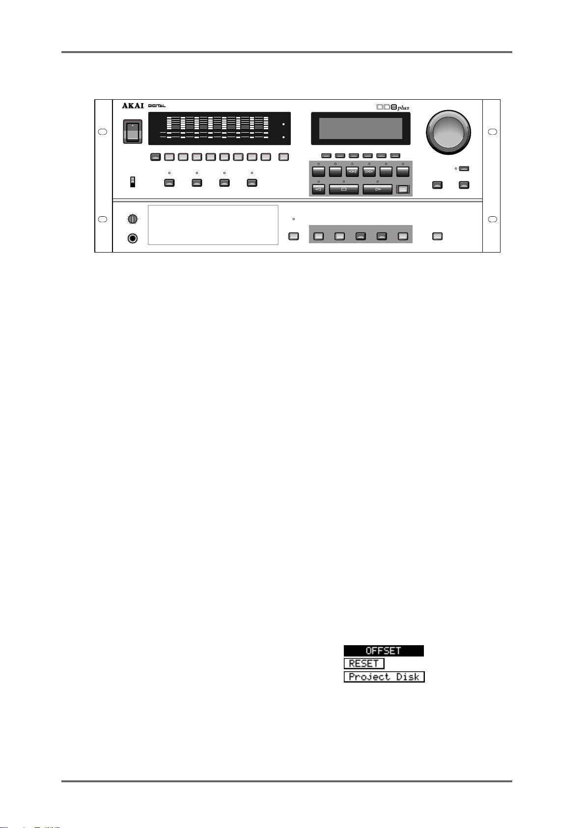
FRONT PANEL
DATA
SYSTEMSTOREGO TO ENTER ESCAPE UNDO
JOG / SPOOL
–
JOG /SPOOL
DATA
+
POWER
PANEL
ENABLED
DISABLED
LEVEL
MIN
PHONES
F 1F 2F
->
IN
OUT
DIGITAL DUBBER
F
3
START
END
4
F 5F
6
REC
ON
OFF
CLIP
REF
ACTIVE
TRK SLIP
12345678
1 2 3 4 5 6 7 8 9 /SYNCALL/ 0
PLAY RECORD NUDGE TRACK SLIP
MAX
CLIP
W/C
RCV
REF
T/C
RCV
CYCLE TO FROM
DISK BUSY
DISK
Next to the Power Switch, the 8 LED barmeter displays are used as peak level meters as well as
indicating the track’s status:
ACTIVE Audio data being played from disk.
TRK SLIP Audio track slipped in time from its original location.
The W/C RCV LED is used to indicate the status of the external word clock input. When external
sync is selected, this indicator will light steadily when the correct word clock signal is being
received. If there is a problem with the word clock signal, this LED will flash.
Similarly, the T/C RCV LED is used to indicate the status of the external timecode input. When
external timecode is being received successfully , the DD8 will play synchronised to that timecode
and the T/C RCV LED will be steadily lit. If at any time, the T/C RCV LED flickers, this indicates
a problem with the external timecode such as dropout. The DD8 will ‘flywheel’ for a short while in
the event of timecode dropout but, if the dropout is too long, the DD8 will stop playing.
Under the power switch, the P ANEL ENABLE/DISABLED switch is used to lock the keys on the
front panel to prevent accidental operation.
The PLAY, RECORD, NUDGE and TRACK SLIP keys are used to select one of the DD8’s
‘PROJECT’ modes, and also determine the current function of the track select keys (1~8 and
ALL).
In the ‘PROJECT’ modes, the track select keys (1~8, ALL) are used for selecting tracks. They
can also be used in some of the setup pages as a numeric keypad. In this situation, the ALL key
is used as ‘0’ and the SYNC key is used as ‘9’.
Under the LCD display are 6 soft keys (F1 ~ F6) used to select items on the LCD.
The type of action performed when one of the soft keys is pressed is indicated by the style of the
soft key display shown on the bottom line of the LCD:
• Accessing another page
• Executing a function
• Moving the cursor to the indicated field
Page 6 DD8
plus
Version 2.20 - September 1998
Page 17
INTRODUCTION - 1
Under the soft keys are the transport keys which are designed to emulate those on an MTR as
closely as possible. The keys are:
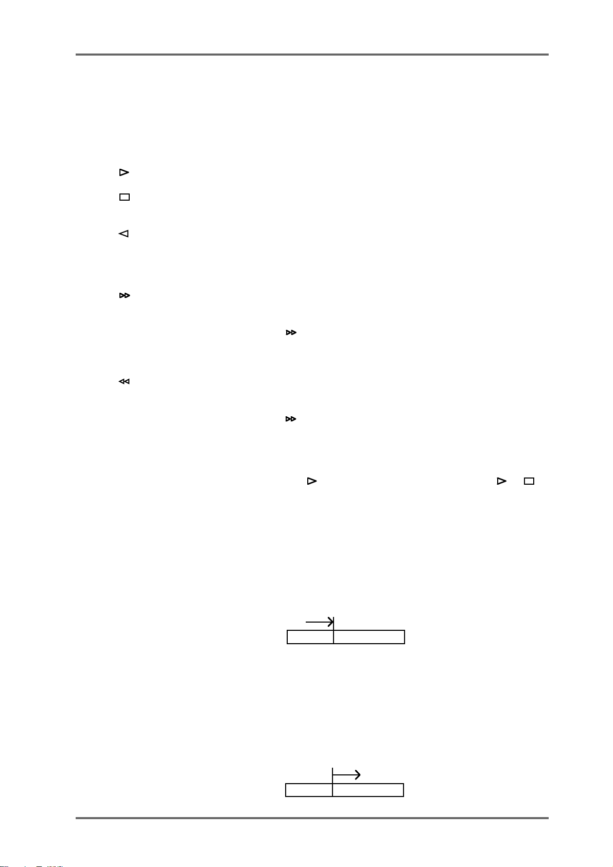
CYCLE When the CYCLE key is pressed, the DD8 will start playback from
the current time and then continue to repeat between the IN and
OUT times previously stored.
This is the PLAY key.
This is the STOP key and will stop playback, recording, rewind and
fast forward.
This is the REVERSE PLA Y key . Pressing it will cause the DD8 to
play backwards. This is a technique used a lot in film applications
where mixing engineers actually mix down backwards in order to
save time. However, please note that you cannot record backwards.
This is fast forward. Pressing it once gives x 10 play speed; pressing it again gives x 100 play speed.
When is pressed during play, the DD8 will fast forward with
‘tape chatter’ just like a standard MTR. In this case, only x 5 play
speed is possible.
This is rewind. Pressing it once gives x 10 play speed; pressing it
again gives x 100 play speed.
When is pressed during play, the DD8 will rewind with ‘tape
chatter’ just like a standard MTR. In this case, only x 5 play speed
is possible.
REC This key allows you to drop in and out of record just like a normal
MTR. Press plus REC together to drop in and press (or ) to
drop out of record.
IN > OUT This will play from the IN point to the OUT point. I.e.:
Because the DD8 automatically places the IN and OUT times at
the start and end of a new recording, you may use PLAY IN>OUT
to check it immediately after recording.
TO This will play up to the NOW time. I.e.:
NOW
PLAY TO
This is useful for checking things prior to editing (i.e. to find a good
edit point) but may also be used for checking things on the NOW
time generally.
FROM This plays from the NOW time for a specified duration. I.e.:
NOW
PLAY FROM
plus
Version 2.20 - September 1998
Page 7DD8
Page 18

INTRODUCTION - 1
Next to the LCD is the JOG/SPOOL wheel. The function of this wheel is selected by the JOG/
SPOOL key. Pressing this once will select the JOG function and the LED will light steadily.
Pressing it again will select the SPOOL function and the LED will flash.
The DATA-/DATA+ keys are used to set or change parameter values.
Next to the disk drive bay is the DISK key. Pressing this enters the DISK mode where you can
select functions which are related to the disk drive(s) attached to the system.
The GOTO and STORE keys access the locator pages which allow you to quickly locate the
transport to the required position.
The ENTER key is used to confirm actions or to complete the entry of names, numbers or
timecode values. The ESCAPE key is used abort or cancel the process without committing it.
This is your ‘escape route’ should you be in a situation where you change your mind. The ESCAPE key can also be used to take you out of the current page and back to the main play/record
mode.
The UNDO key allows you to undo/redo the last thing you did. If you make a mistake and do
something you’re not happy with, press UNDO and the original data will be restored. If you then
find that you preferred the mistake, press UNDO again to restore the previous version.
NOTE 1: The UNDO function only refers to recording and editing. Y ou cannot undo anything
else. For example, if you load a project and change your mind, you cannot undo that. If you
select some tracks for edit when you really meant to select them for record, you cannot undo
that.
NOTE 2: IT IS NOT POSSIBLE TO USE UNDO IF YOU DELETE A FILE (I.E. A PROJECT)
BY MISTAKE. PLEASE TAKE CARE WHEN DELETING FILES.
The SYSTEM key is used to select pages where you can set many parameters to select the
current operational state of the DD8.
Finally, on the other side of disk drive bay, the PHONES connector outputs a mix of all tracks
selected for playback. The headphone level is adjusted by the LEVEL control above the connector.
Page 8 DD8
plus
Version 2.20 - September 1998
Page 19
FRONT PANEL - INSERTING AN MO DISK
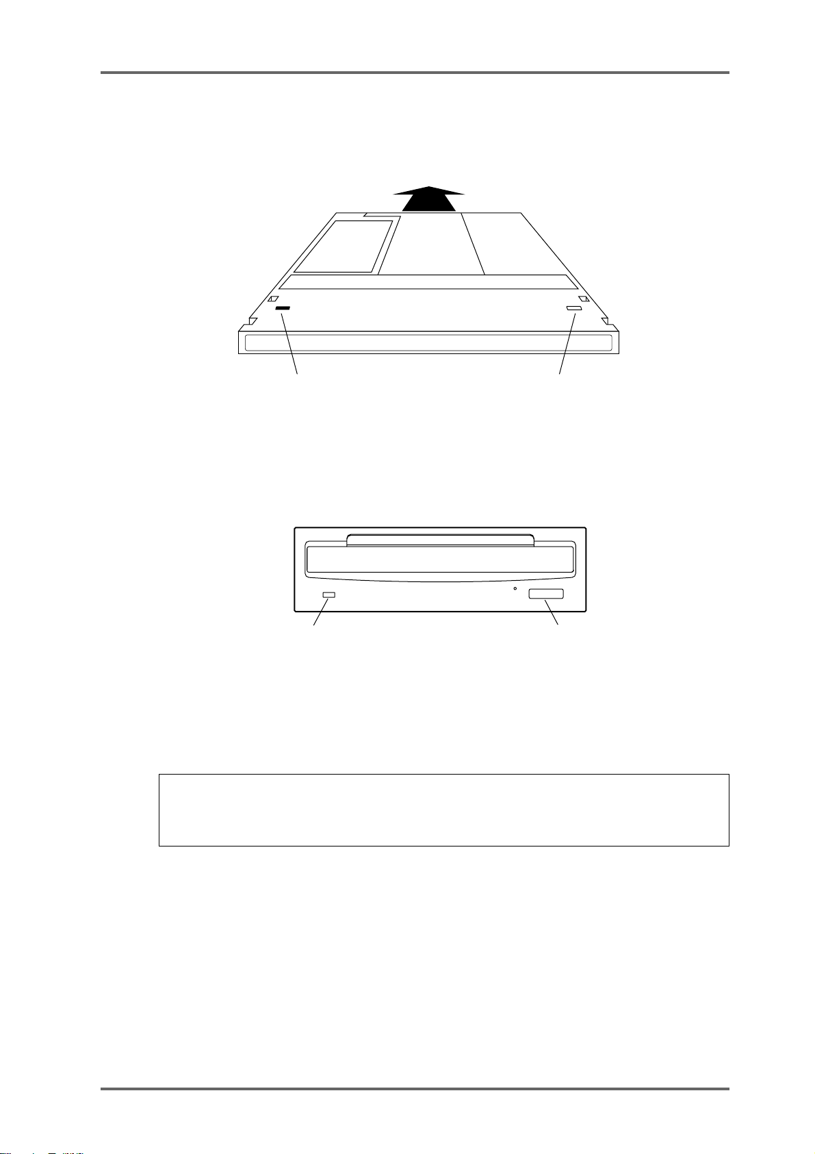
Assuming you have an MO drive installed, the disk is inserted thus:
INTRODUCTION - 1
WRITE PROTECT SWITCH
(This side)
WRITE PROTECT SWITCH
(Other side)
The side you wish to use is inserted face up. Power must be on for the disk to be accepted as the
load mechanism is motorised.
Disk Activity Led Eject switch
When the disk is in use (i.e. playing back, recording, saving, loading, etc.), the DISK ACTIVITY
LED will flash.
To eject the disk, press the DISK EJECT button. Power must be on for the disk to be ejected as
the mechanism is motorised.
NOTE: If there is some problem ejecting the disk and/or power is not applied to the drive, you
can eject the disk by inserting a small metal tool in the small hole alongside the disk eject
button. Something like a rolled out paper clip will do it but a special tool is recommended. This
tool may accompany the drive unit.
It is possible to write protect MO disks to prevent accidental erasure, editing, formatting, etc.. To
do this, slide the WRITE PROTECT switch to the PROTECT position. If you only intend to
playback from the disk, it is a wise precaution to write protect the disk to prevent accidental
damage to a project.
plus
Version 2.20 - September 1998
Page 9DD8
Page 20
INTRODUCTION - 1
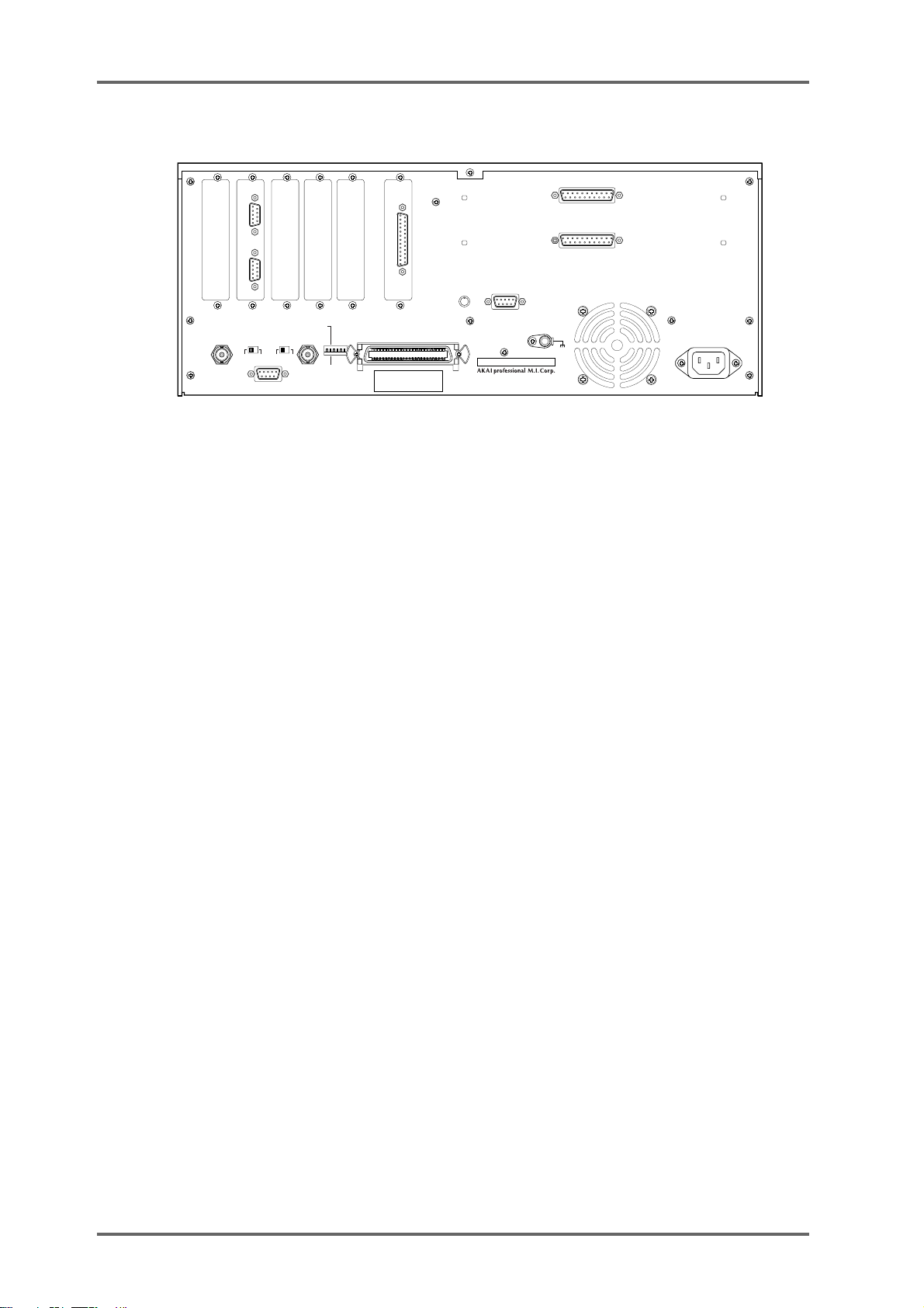
REAR PANEL
ANALOG INPUT
ANALOG OUTPUT
GND
AKAI NET.
BIPHASE
IN
OUT
ON OFF
SYNC
TERM
EXPANSION
TERM
ON OFF
SYNC
IN/ OUT
MASTER
AES/EBU
DIGITAL I/O
PRE-READ
LEVEL
MAX
MIN
SCSI-B ID
T421
NC
OFF
ON
SLAVE
SCSI-A
MODEL NUMBER DD8pl us
1-3
, HIRANUMA 1-CHOME, NISHI-KU,
YOKOHAMA, JA PAN
MADE IN JAPAN
OPTION SLOTS
There are six slots on the rear panel for installing option cards. The first four slots from the left hand
side are for general purpose interface cards such as the IB-805R (RS422 interface) or the IB-806B
(Biphase interface). The fifth slot is for a digital audio interface card such as the IB-D8TIF (TDIF
interface), IB-D8MA24 (AES/EBU interface) or IB-804A (ADAT interface). The final slot is for the
connector to the Tascam MU-8824 Meter Bridge (this is part of the IB-D8TIF option card).
There are two more slots available for installing the analog option cards IB-D8AD (8-channel analog
input) and IB-D8DA (8-channel analog output).
AKAINET CONNECTOR
This connector is used to connect the DD8 to the DL1500 Remote Controller
TERMINATOR SWITCHES
These switch selects 75Ω termination for the SYNC connector for use with video sync signals
and 50Ω termination for the AKAINET connector.
SYNC CONNECTOR
This BNC can accept either TTL wordclock or video sync signals (such as ‘black and burst’
house sync signals) and is used to synchronise the DD8 to an external clock source.
EXPANSION CONNECTOR
This connector is used to attach the optional RC15 User Assignable Remote Controller.
SCSI-B ID SWITCHES
These DIP switches are not in use at the moment (Note that this switch has no effect on the
SCSI-A bus).
SCSI-A CONNECTOR
This 50-pin Amphenol connector is used to connect external SCSI drives to the DD8.
GROUND TERMINAL
This terminal is provided to allow you to earth the DD8 in the event of ground loops.
MAINS INPUT
Mains power is connected here.
PRE-READ LEVEL
This control is used to adjust the level of the oscillator signal that will be generated at the preread output connector.
Page 10 DD8
plus
Version 2.20 - September 1998
Page 21

INTRODUCTION - 1
PRE-READ CONNECTOR
This connector can be used to replace the ‘pre-read’ output generated by some dubbers that
have a second playback head mounted before the main playback head. Note that the DD8 does
not generate an audio signal here. Instead, it uses an oscillator which is switched on and off as
the playback signal reaches a preset threshold.
plus
Version 2.20 - September 1998
Page 11DD8
Page 22
INTRODUCTION - 1
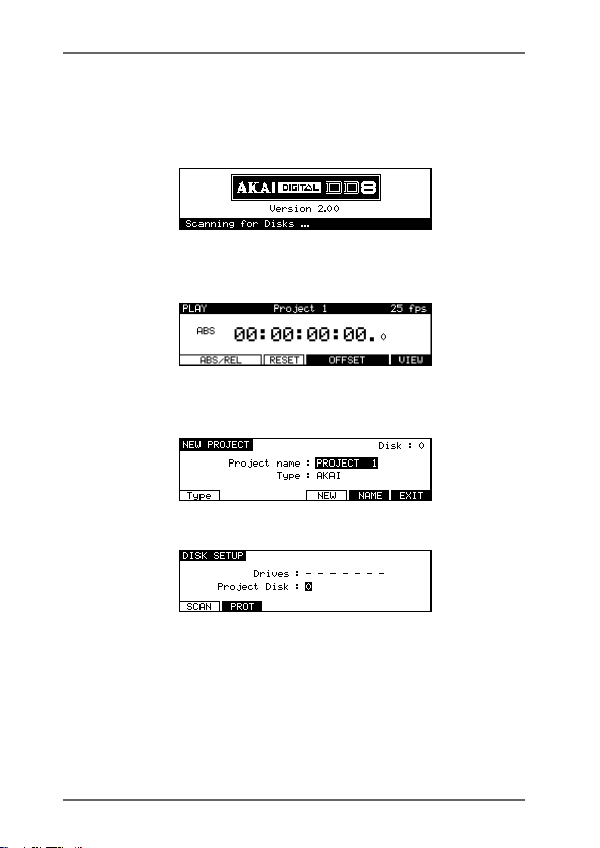
POWERING UP THE DD8
It is recommended that the following power up procedure is observed when turning the system
on:
First, turn on any disk drives that may be connected to the system. Next, turn on the DD8. You
will see this screen display momentarily:
The DD8 will look at the disk drives attached to the system. If a disk containing a valid PROJECT
is found, it will be loaded automatically and you will see the main playback screen:
If no projects are found, the DD8 will enter the NEW PROJECT page in DISK mode, which will
be explained later in Disk mode, to allow you to setup the disks attached to the system and
create a new PROJECT:
If no disk is found, it goes directly to the DISK SETUP page in DISK mode:
In this case, check the connections to the disk drive (and SCSI termination) and then press
the SCAN key to search the SCSI bus again.
Page 12 DD8
plus
Version 2.20 - September 1998
Page 23
PLAY MODE - 2
PLAY MODE
The PLAY mode is the default mode when a Project is loaded. It can also be accessed at any
time by pressing the PLAY key under the barmeters. Pressing the track keys 1-8 located under
the barmeters select the playback tracks to be muted. The tracks with lit LEDs indicate muted
tracks. Pressing the track key again disables the mute.
The Soft Keys’ functions depend on the External Time Source selected in the SYSTEM/SYNC
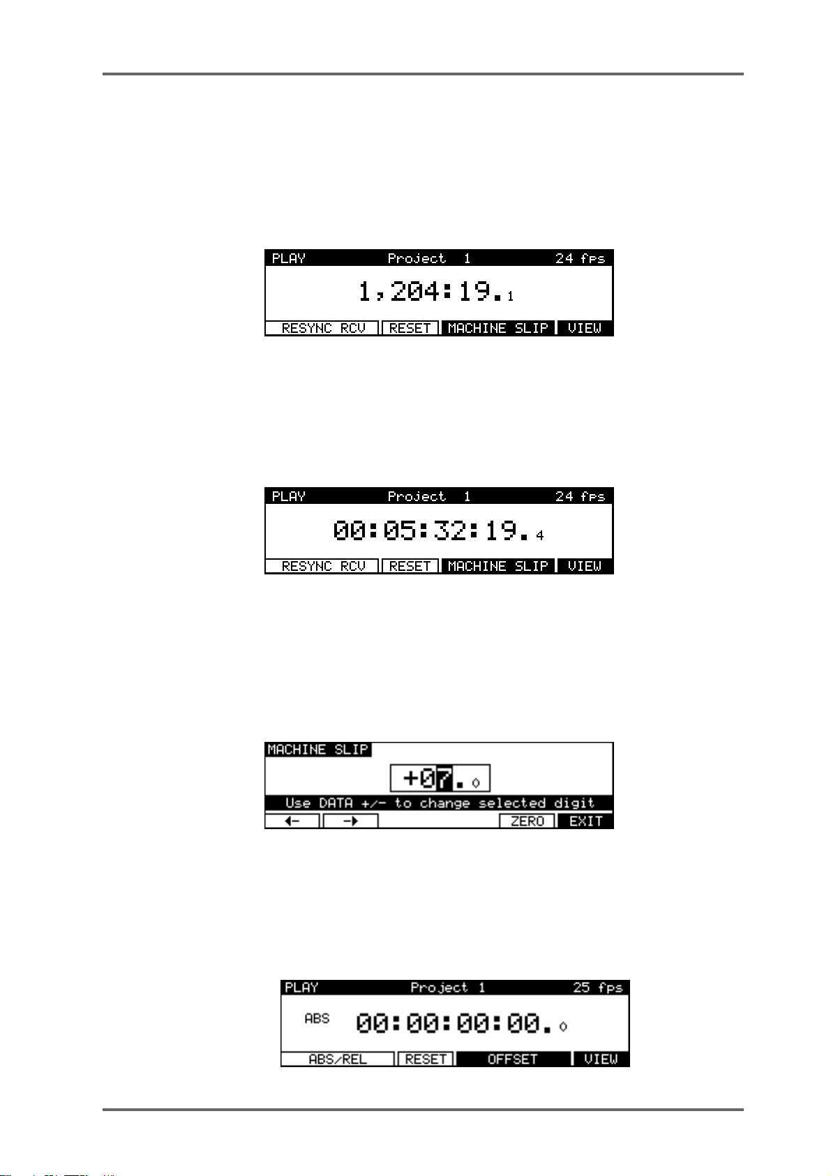
menu. When a Biphase time source is selected, the PLAY screen will look similar to this:
The top line of the screen shows the name of the current Project, as well as the current frame
rate of the timecode display.
The time display style and sub-frame display depend on the parameters set in the SYSTEM/
DISPLAY menu. In the example shown above, the timecode display style has been set to display
footage. However, it is also possible to select ‘conventional’ timecode formats in which case the
display will look something like this:
The top line of the screen shows the name of the current Project, as well as the current frame
rate.
Pressing the RESYNC RCV key (F1/F2) resets the biphase reader to the current position.
The RESET key (F3) resets the time counter to zero at the current position.
Pressing MACHINE SLIP (F4/F5) takes you to the MACHINE SLIP page :
This page allows you to slip the DD8’s time with respect to the biphase machine. F1 and F2 are
used to move the cursor to the correct position (frames or sub-frames), and the DATA +/- keys
are used to adjust the value. Note that the Sub-Frame value (1/10th frame, 1/4th frame, 1/2
frame) depends on the setting in SYSTEM/DISPLA Y (10th Frame, Film Perfo, V ideo Field). The
ZERO key (F5) resets the offset to zero.
When an external time source other than biphase is selected, the PLAY screen will look like this:
plus
Version 2.20 - September 1998
Page 13DD8
Page 24
PLAY MODE - 2
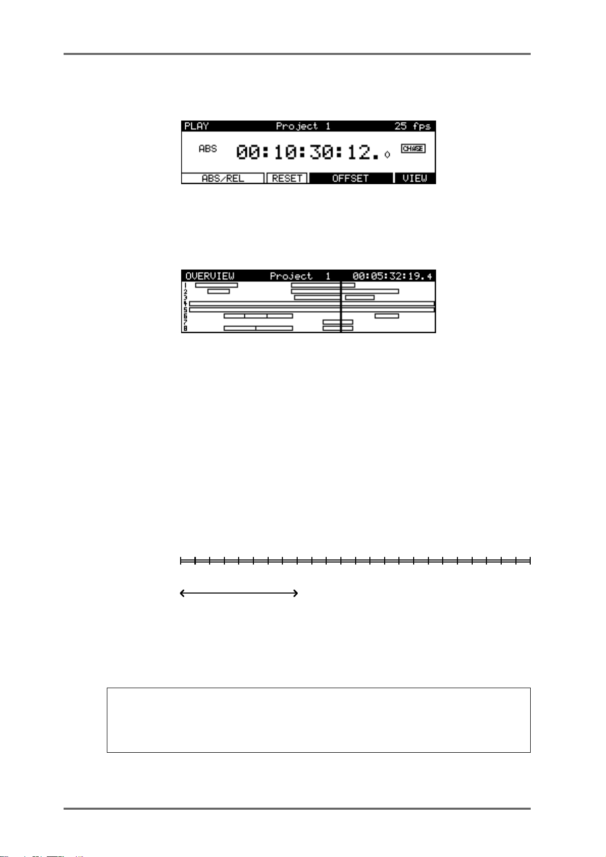
When an External Time Source is selected and the SYNC key is switched on, an additional
display on the main PLAY screen indicates when the DD8 is chasing the external time:
When the DD8’s internal time is at the same position as the external time (and the sample rate is
synchronised to the speed of the external time source), the CHASE display will change to LOCK.
Pressing the VIEW key (F6) switches to the OverView display :
This page shows a static view of the entire Project, with the NOW time scrolling across the
screen. The ESCAPE key (or any mode key) is used to exit this display.
Returning to the main PLAY screen, sometimes, you may prefer to set an offset between the
DD8’s timecode display and the timecode position of an external machine. For example, your
project may start at 00:00:00:00 but the visuals start at 10:00:00:00. Using the soft keys on this
page, you may set offsets so that the two machines play in sync without having to extensively
modify the project’s start time.
Pressing the ABS/REL (F1/F2) key sets the time display in absolute mode.
Pressing the ABS/REL (F1/F2) key again sets the time display in relative mode which allows the
00:00:00:00.0 reference time to be placed at a time other than absolute zero. For example:
ABS(solute)
REL(ative)
0 23.59
-8
ZERO IS AT : + 08:00:00:00.0
8
0
15.59
Pressing the RESET (F3) key resets the relative time to zero at the current position.
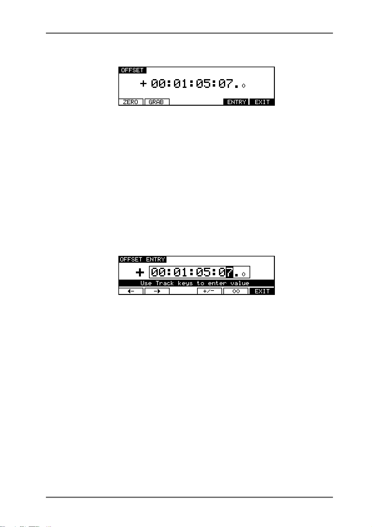
Pressing the OFFSET key (F4/F5) takes you to the Offset page where you can manually enter
the time offset between ABS time and REL time.
NOTE: You may find it useful when starting a project from scratch to always start at, say,
1 hour and use the relative time display so that the project effectively still starts at zero. In this
way , if you suddenly find you need to add cues before 00:00:00:00, you can. If you use absolute and start at zero, you will first have to slip all cues in the project forward to accommodate
the new cues.
Page 14 DD8
plus
Version 2.20 - September 1998
Page 25
PLAY MODE - 2
SETTING TIMECODE OFFSETS
Pressing the ZERO (F1) key resets the offset to zero. When following timecode from an external
machine, pressing the GRAB (F2) key grabs the offset between the current NOW time (internal)
and the current External Time value.
If the project starts at 00:00:00:00.0 but the incoming timecode starts at 1 hour, you should set
an OFFSET of -01:00:00:00.0. This will subtract 1 hour from the incoming timecode, thereby
effectively providing the DD8 with timecode starting at 00:00:00:00.0. Conversely, if the project
starts at, say, 10 hours but the incoming timecode starts at 1 hour, you would need to set an
offset of +09:00:00:00.0 , adding 9 hours to the incoming timecode so that it plays from 10 hours.
In cases where the project and the incoming timecode both start at odd times (for example,
when the project starts at 02:23:45:23.0 and the incoming timecode starts at, say, 09:12:12:14.0),
your best bet is to use the GRAB softkey. Locate the project and the incoming timecode to their
respective start times and press GRAB. The offset will be calculated automatically.
Pressing ENTRY (F5) enters the Offset Entry page which allows you to manually enter an offset
value or nudge the current offset value:
Soft keys F1 and F2 can be used to move the cursor to the sub-frame field, or any of the other
fields. The offset time is then entered using the track keys as a numeric keypad or the current
digit can be nudged using the DATA +/- keys.
The offset sign (plus or minus) can be toggled by pressing the +/- key (F4).
plus
Version 2.20 - September 1998
Page 15DD8
Page 26
RECORD MODE - 3
RECORD MODE
The RECORD mode is the default mode when a New Project is created. It can also be selected
by pressing the RECORD key below the barmeters. In this mode, the track select keys (1~8) are
used for selecting tracks to record onto.
The Time Display Style and Sub-Frame display depend on the according parameters in the
SYSTEM/DISPLAY menu. However, “Free on Disk” is always shown in real time (hh:mm:ss).
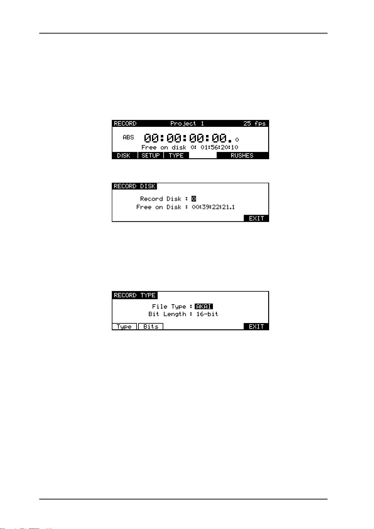
When not recording, the following display is shown:
The top line of the screen shows the name of the current Project, as well as the current frame
rate. Pressing DISK (F1) takes you to the Record Disk page :
Here you may select the SCSI ID of the disk onto which new audio will be recorded. This page
also shows you how much available recording time there is on tracks enabled for record.
Pressing SETUP (F2) takes you directly to the RECORD SETUP screen which is described later
in this manual in the System Section.
Pressing TYPE (F3) takes you to the RECORD TYPE page where you can select certain options
for new recordings:
The TYPE key (F1) is used to move the cursor to the FILE TYPE field. The BITS key (F2) is used
to move the cursor to the BIT LENGTH field.
FILE TYPE This selects the type of audio file that will be created when new recordings
are made. The options available in this field depend on the format of the
selected Record Disk.
• AKAI: This is the DD’s native audio file format and is only available when
the selected Record Disk is an AKAI format
• AIFF:This is Apple’s “Audio Interchange File Format” that is used by many
Macintosh software applications. The AIFF option is only available when the
selected Record Disk is Macintosh format
• SD-II: This is the native audio file format used by Digidesign Pro Tools and
some other Macintosh software applications. The SD-II option is only available when the selected Record Disk is Macintosh format
• AKAI->FAIRLIGHT: This allows special Akai audio files to be created which
are intended for playback on a Fairlight MFX3plus system fitted with Akai
File Exchange support. This option is only available when the selected Record
Disk is an AKAI format
Page 16 DD8
plus
Version 2.20 - September 1998
Page 27
BIT LENGTH This selects the audio bit length for new recordings.
• 16-bit: This is the compact Disc standard.
• 20-bit: This option allows 20-bit audio to be recorded, giving greater resolution and headroom.
• 24-bit: This option allows 24-bit audio to be recorded, giving even greater
resolution and headroom.
• 20-bit (packed): This is a special option that is only available when recording AKAI format audio files. Typically, 20-bit audio occupies the same space
on disk as 24-bit audio (the extra 4-bits of storage space in each sample
being wasted). The 20-bit ‘packed’ mode avoids this waste of space by writing the audio to disk in a special pattern.
RECORD MODE - 3
24-BIT :
20-BIT :
20-BIT PACKED :
Note that this mode does
not
involve any ‘audio compression’. It just places
Sample 3Sample 1 Sample 2
Sample 3Sample 1 Sample 2
Sample 3Sample 1 Sample 2
the data on disk in an optimal manner to maximum disk storage space and
bandwith.
Once you have selected your recording tracks, to record, simply press PLA Y (to start playback)
and then press PLAY and the RECORD key together. The track key(s) will be steadily lit as will
the transport RECORD key.
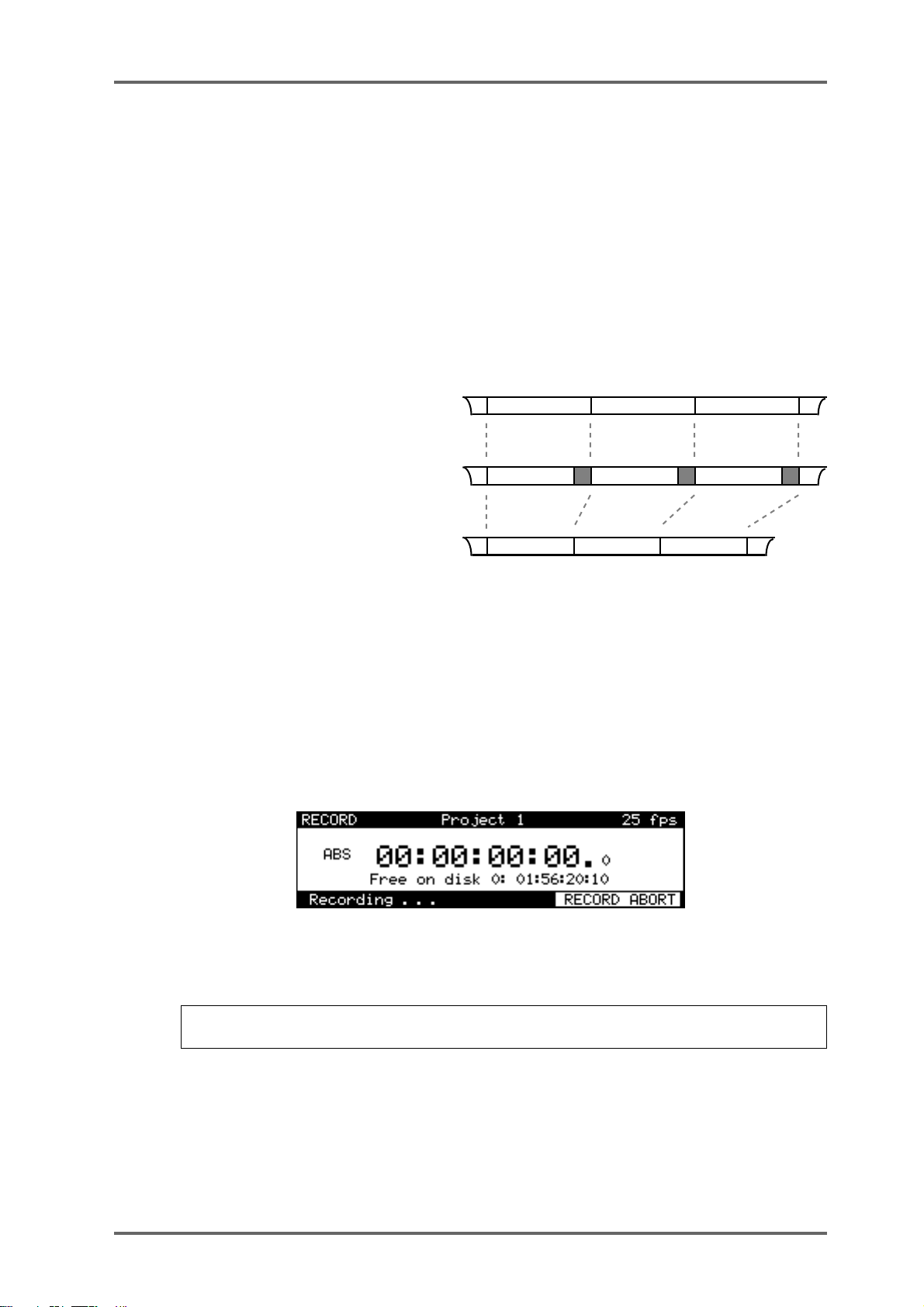
During recording, the screen changes as follows :
Pressing RECORD ABOR T (F5/F6) aborts the recording process.T o stop recording, press STOP.
To drop out of record (i.e. stop recording but keep playing), simply press PLAY - the DD8 will
drop out of record and keep playing.
NOTE: There is a minimum time before you can punch in to record again after punching out.
This is due to disk speed and will depend on the drive you are using.
It is also possible to start recording from stop by pressing the REC key first and
then
PLAY. You can stop recording by pressing PLAY again or by pressing STOP.
plus
Version 2.20 - September 1998
pressing
Page 17DD8
Page 28
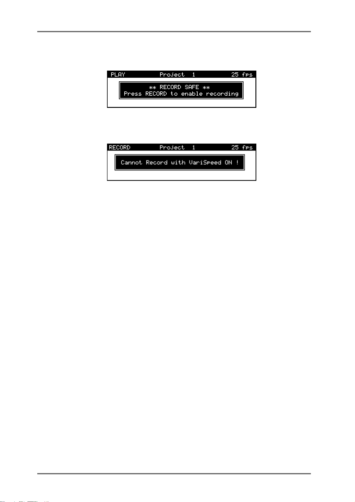
RECORD MODE - 3
If the DD8 is in a mode other than RECORD (i.e PLAY, NUDGE or TRACK SLIP), the following
message will appear when you try to start recording:
If V ariSpeed is ON (and different from 0 %), the following prompt will appear when you try to start
recording:
UNDOING A RECORDING
If you don’t like the recording you just made, the simplest way to repair it is probably to record
over it just like tape. Another way out of a recording disaster is to undo the last recording you
made by pressing the UNDO key (the key’s LED will light). Of course, should you change your
mind, you can redo the recording by pressing the UNDO key again (the LED will switch off).
Page 18 DD8
plus
Version 2.20 - September 1998
Page 29
RECORD MODE - 3
RECORD RUSHES
When recording ‘dailies’ at a film or video shoot, recordings are made referenced to ‘time of day’
timecode on a portable recorder of some kind. However, due to the nature of dropping in and out
of record, the timecode becomes discontinuous. For example, the first recording may start at
10am and finish a minute later. As the scene is reset, the next recording may start at 10:15:13am
and last 2 minutes. However, on the recording device used at the shoot, the two recordings will
be adjacent, separated by a gap of a few seconds and there will be a break in the recorded
timecode.
While making ‘normal’ recordings, the DD8 will drop out of recording if it detects a dropout in the
received timecode. Hence, it would be necessary to manually put the DD8 back into record to
transfer the audio in the example above. The Record Rushes function overcomes this and
allows continuous recording on the DD8 despite breaks in the source reel’s timecode. When the
transfer is made, the rushes will be placed at their actual (original) timecode positions. For
example:
10:15:13
Source Reel 'rushes'
10:00:00 10:32:45
Rushes transferred to DD8
10:00:00 10:15:13 10:32:45
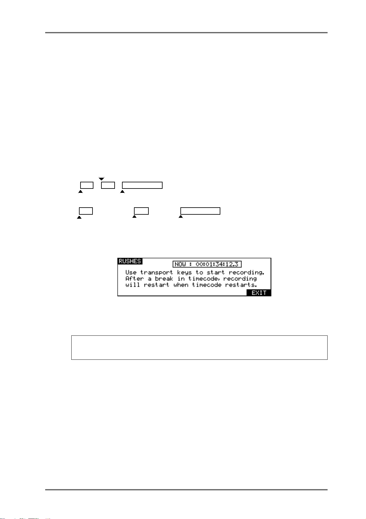
T o use the rushes function, press RECORD RUSHES (F5/F6) on the main record page. You will
see this screen:
You should start the source machine playing and drop into record as normal on the DD8. When
a recording is started from this page, the normal recording behaviour is modified so that recording will restart after a break in timecode.
NOTE: Of course, as you are recording to external timecode, the correct parameters should
be selected in the SYSTEM pages to enable the appropriate time source. Y ou will receive an
error message if these settings are not correct.
plus
Version 2.20 - September 1998
Page 19DD8
Page 30

NUDGE - 4
NUDGE
The NUDGE function is used to adjust the position of a region (defined by the IN and OUT
points), by small increments (frames or sub-frames) using DATA +/- keys. The selected region
can be auditioned using the play IN->OUT key.
Pressing the NUDGE key will show the following prompt:
After the appropriate tracks are selected and ENTER is pressed, the following screen will appear:
It is not possible to select different tracks once the Nudge mode has been entered. When entering the Nudge mode, the displayed amount is always zero. The final amount is committed when
exiting the NUDGE mode.
Pressing SELECT CUE (F3/F4) selects all of the cues at the current time on the track(s) selected for Nudge. (i.e. it sets the IN time at the beginning of the first Cue and the OUT time at the
end of the last cue).
The cursor keys (F1/F2) are used to select the digit to be adjusted. The Sub-Frame value (1/10
frame, 1/4th frame, 1/2 frame) depends on the setting in SYSTEM/DISPLA Y (10th Frame, Film
Perfo, Video Field).
Pressing SOLO (F6) toggles the SOLO function ON/OFF. When SOLO is activated, only the
track(s) selected for Nudge are heard on the headphone output.
Page 20 DD8
plus
Version 2.20 - September 1998
Page 31

TRACK SLIP - 5
TRACK SLIP
The Track Slip function is used to adjust the position of a whole track by small increments
(frames or sub-frames) using DATA +/- keys.
Pressing the TRACK SLIP key will show the following screen :
Pressing FRAMES (F4) or SUB-FRAMES (F5) toggles between Frames and Sub-frames. The
Sub-Frame value (1/10th frame, 1/4th frame, 1/2 frame) depends on the setting in SYSTEM/
DISPLAY (10th Frame, Film Perf, Video Fields).
Pressing SOLO (F6) will toggle the SOLO function ON/OFF. When SOLO is activated, only the
track(s) selected for slipping will be heard at the headphone output.
It is possible to select multiple tracks for slipping, but each track will retain its own amount :
The Slip amount of each track is memorised, and displayed when entering the SLIP page. When
the Slip amount of a track is different from zero, the according TRK SLIP LED (under the Meters)
will be steadily lit, even when returning to another mode. This condition can be thought of as a
‘Track slip preview’ - the track’s playback start time will be adjusted by the appropriate amount
but the track’s data is not actually edited.
Pressing ZERO (F2) will slip the selected tracks back to their original position and reset the
display to zero.
Pressing COMMIT (F1) permanently slips the selected tracks and resets the display to zero.
NOTE 1: When a TRACK SLIP amount is non-zero (i.e. while a TRACK SLIP is being previewed), it is not possible to record or edit on this track. The slip time must be COMMITed to
allow these operations to be used.
NOTE 2: The TRACK SLIP function is not recognised by the DR8/DR16 (or DD1500 prior to
V2.30). When a disk with TRACK SLIP is loaded into these machines, the audio will playback
at its original time. To overcome this, the TRACK SLIP should be COMMITed while the disk
is connected to the DD8.
plus
Version 2.20 - September 1998
Page 21DD8
Page 32

LOCA TOR - 6
LOCATOR
Once you start to build up a project, you need a convenient way of getting around it. Perhaps the
simplest way is to use the rewind and fast forward keys.
However, you often need to go to very specific points in a project. To facilitate this, the DD8 has
a powerful autolocator that allows you to store up to 100 numbered locate memories as well as
being able to locate to the start, the end and the IN, MARK and OUT points. You may also locate
directly to timecode values.
IN / OUT are used for the CYCLE Play function, as well as for marking a region for the NUDGE
function.
MARK is a dedicated memory for Biphase synchronisation. It is set to define a sync point between audio and film picture (usually a cross before the first frame).
STORE
Pressing the STORE key will show the following screen :
• Pressing IN (F1) stores the current NOW time as the IN point.
• Pressing OUT (F2) stores the current NOW time as the OUT point.
• Pressing MARK (F3) stores the current NOW time as the MARK point.
Pressing MEMORY (F6) goes to the STORE MEMORY page :
This page allows the current time to be stored in one of the locator memories (numbered 00 to
99). The memory number is entered via the Track keys (ALL/0, 1-8, SYNC/9). Y ou can also store
a series of locate points using the STORE NEXT key. Each time you press this key, the current
time will be stored and the memory number will be incremented.
GOTO
Pressing the GOTO key will show the following screen :
• Pressing IN (F1) locates to the previously stored IN point.
• Pressing OUT (F2) locates to the previously stored OUT point.
• Pressing MARK (F3) locates to the previously stored MARK point.
Page 22 DD8
plus
Version 2.20 - September 1998
Page 33

LOCATOR - 6
LOCATING TO TIMECODE POSITIONS
You may locate to a timecode position by pressing GOTO followed by F5 (LOCATE). Use the
track keys as a numeric keypad to enter the required time. Values enter from the right and time
divisions (i.e. hours, minutes, seconds and frames) are confirmed using the 00 ‘double zero’ soft
key (F5).
For example, to enter a value of 1 hour, 23 minutes, 12 seconds, 12 frames, type the following:
1, 00, 2, 3, 00, 1, 2, 00, 1, 2, ENTER
You will see the following display in the selected timecode field as you enter the numbers:
The important thing to remember is to ‘confirm’ the time division using the numeric keypad’s 00
‘double zero’ key.
If you wish to enter a timecode value with a sub-frame, use the procedure described above but
press the <- (F1) or -> (F2) keys to move the cursor to the sub-frame field.
LOCATING TO LOCATOR MEMORIES
To locate to a previously stored locate memory, press GOTO, F6 (MEMORY) and enter the
appropriate memory number 0-99 using the track keys (ALL/0, 1-8, SYNC/9) as a numeric keypad. Finally, press ENTER (see STORING LOCATE MEMORIES).
LOCATING TO THE START OR END OF A PROJECT
T o locate to the ST ART or END of a project, simply press GOTO, ST ART (Rewind key) or GOTO,
END (Fast Forward key) and you will be taken directly to these positions.
plus
Version 2.20 - September 1998
Page 23DD8
Page 34

DISK P AGES - 7
DISK PAGES
The DISK key allows access to the pages which are used for general disk management such as
renaming and deleting files, formatting disks, copying disks, etc..
The Disk management has some ‘intelligence’ of its own, so the action of this key depends on
the State of the DD8, and on the contents of the Project Disk.
If no project has been loaded, pressing the disk key will take you to the following screen:
On this screen, the ‘Drives’ field shows the SCSI IDs of all drives that have been detected.
0-6 ... there is a formatted disk drive on this ID
F ... there is an unformatted disk drive on this ID
T ... there is a SCSI Tape drive on this ID
- ... there is no drive recognised on this ID
Pressing the SCAN key (F1) will re-scan the SCSI bus for drives. This can be used to allow the
DD8 to detect an MO disk that is inserted into the drive after entering this page.
When a formatted project disk containing one or more projects is selected, pressing the SELECT key (F5/F6) will take you to the LOAD PROJECT page. If the disk is formatted but does
not contain any projects, pressing this key will take you to the NEW PROJECT page allowing
you to create one. As well as disks created on other Akai DD-series products, the DD8 is also
able to recogise disks formatted on other systems including Apple Macintosh, Waveframe and
Timeline MMR-8.
If the selected project disk is not formatted for the DD8, the screen will change to show:
Pressing FORMAT DISK (F5/F6) will take you to the format page to initialise the disk.
WRITE PROTECT PAGE
Pressing the PROT key (F2) on the DISK SETUP page will take you to the WRITE PROTECT
page:
When the WRITE PROTECT parameter is set to ON, the machine is prevented from writing any
data to disk. This can be used to designate a machine as a ‘player’ as when write protection is
enabled, all record and editing functions are prohibited. This is also useful as a safety feature
when working with drives that do not have their own write protection.
Page 24 DD8
plus
Version 2.20 - September 1998
Page 35

DISK P AGES - 7
NEW PROJECT PAGE
This page can be accessed either from the DISK SETUP page (as described previously) or by
pressing NEW (F5) on the LOAD PROJECT page.
Pressing NEW (F4) will create a new Project (using Flash ROM settings), with the name shown
in the Project Name field. After creating a new project, the DD8 will go to Record Mode ready to
make new recordings.
The TYPE field is used to select the type of project that will be created. The options available will
depend on the format of the selected disk.
The options available are:
AKAI To create a new AKAI project on an Akai format disk
PT 4 To create a new “Protools 4” Session on a Macintosh format disk
PT 24 To create a new “Protools 24” Session on a Macintosh format disk.
If you do not like the default project name, pressing NAME (F5) enters the Project naming process :
Use the F1 (<-) and F2 (->) keys to move the cursor to the left/right. Use the DATA+/- keys to
scroll through the available characters in order to set the name for the new project. When you
are finished, press ENTER to set the new project name.
LOAD PROJECT PAGE
This page is accessed from the DISK SETUP page described previously. The layout of this
screen changes slightly depending on the format of the seleced disk. When an Akai format disk
is selected, you will see the following page:
The Disk field is for information only and shows the ID that was selected on the DISK SETUP
page. On the right of the screen, the list of the Projects is displayed. If the disk contains more
than four Projects, arrows will appear to show that there are more Projects above or below.
The DATA +/- keys are used to scroll through the list of Projects.
Pressing DIR (F1) goes to the DIRECTORY page
(see below)
where you can view all the files
on the currently selected disk.
Pressing SAVE (F2) goes to the SAVE PROJECT page where you can manually save the
current project or convert it to another format.
plus
Version 2.20 - September 1998
Page 25DD8
Page 36

DISK P AGES - 7
Pressing UTILITIES (F3/F4) goes to the UTILITIES page
(see below)
where you can select
various disk functions such as backup and copy.
Pressing NEW (F5) goes to the NEW PROJECT page where you can create a new project.
Pressing LOAD (F6) loads the Project currently selected by the highlighted cursor. After a project
is loaded, the DD8 goes directly to the PLAY mode. If the Project has been saved with SYNC
enabled, the DD8 will set itself into CHASE mode (waiting for external time source)
Page 26 DD8
plus
Version 2.20 - September 1998
Page 37
DISK P AGES - 7
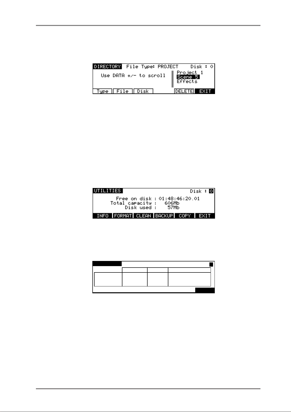
DIRECTORY PAGE
The Directory page allows you to view all files on a selected disk. The default is to show Project
files on the disks, but there are other files as well.
Pressing T ype (F1) moves the cursor to the File T ype field which allows you to select which type
of file will be displayed.
Pressing File (F2) moves the cursor into the list of files and allows you to scroll through the list
using the DATA +/- keys.
Pressing Disk (F3) moves the cursor to the Disk field which allows you to select the SCSI ID of
the drive you wish to view.
Pressing DELETE (F5) deletes the Project selected by the cursor.
UTILITIES PAGE
Pressing UTILITIES on the LOAD PROJECT page will take you to the following screen.
Here you may perform certain disk utility routines. These are:
DISK INFO
Pressing INFO (F1) will display the following screen:
DISK INFO
MEDIA
DATA
AUDIO
SONY SMO-F521-()() 1.()4
Format: Normal
total used available
622Mb
612Mb
9Mb
91Mb
()Mb
91Mb
53()Mb
512Mb
ID:()()
9Mb
EXIT
This screen gives more information about the type and size of the disk, how much of the disk is
used and how much is free. These values are expressed in Megabytes.
The only field accessible in this page is the ID field in the top right hand corner. Here, you may
select to view other disks that may be connected to the system.
plus
Version 2.20 - September 1998
Page 27DD8
Page 38

DISK P AGES - 7
FORMATTING DISKS
Pressing the FORMAT key (F2) in the UTILITIES screen will take you to the disk format page :
By pressing Operation (F2/F3), you may select whether to just format the disk or format the disk
and certify it afterwards. Formatting is very fast but if you select FORMA T & CER TIFY, this may
take a while depending on the size of the disk. However, if this is the first time the disk is being
formatted, it is recommended you run the certify process as well. This will mark out any bad
blocks on the disk and prevent them from being used which will make the disk more reliable and
not prone to read errors.
Pressing T ype (F1) moves the cursor to the FORMAT TYPE field that is used to select the type
of the directory that will be created on the disk when it is formatted. The options are:
DD-PLUS This is the current Akai DD-series disk format which allows 4000 files to be
saved to a single disk and will give the best performance for real-time recording
and playback of audio.
MACINTOSH This allows the disk to be formatted in Macintosh HFS format. Note that this
option will create a single volume, erasing all existing partitions on the disk. If
you want to create multiple partitions, it will be necessary to use a third-party
Macintosh disk formatting application.
When the MACINTOSH format option is used, the disk may later be read on
any Macintosh subject to the following limitations in various versions of the Mac
OS:
• System 7.1 can only support volumes up to a maximum size of 2 gigabytes
• System 7.5 can recognise volumes up to a maximum size of 4 gigabytes
(which is currently the maximum size supported by Protools and many other
products)
• System 7.5.3 and above can recognise volumes up to a maximum size of 2
Terrabytes
NOTE: While the DD8 can properly format a Macintosh hard disk or MO, it does not install any
type of Macintosh driver software on the disk. Therefore, disks formatted on the DD8 will
require third-party mounting software in order to appear on the Macintosh desktop.
COMP A TIBILITY NOTE: Disks made on DD1500s or DR8/DR16s using software earlier than
V2.1 can be used on the DD8. However, please be aware that disks formatted with the
extended directory cannot be used on DD1500s running software earlier than V2.1.
Once you have set everything as you want, pressing FORMAT DISK (F4/F5) will show the following prompt :
Page 28 DD8
plus
Version 2.20 - September 1998
Page 39

DISK P AGES - 7
If you press ENTER, you will receive this screen:
During the formatting process, you may press the ESCAPE key to abort
If the disk is write protected, you will receive the prompt:
After a few seconds, the prompt will disappear and you will be returned to the main FORMAT
DISK page. You should eject the disk and take the write protect off. However, there may be a
reason the disk is write protected so it may be wise to leave the format page and check the
contents before proceeding as there may be important data on it that needs to be kept.
NOTES ON FORMATTING DISKS
The full format and certify procedure takes between 20 minutes and an hour, depending on
the size of the disk. During this time, the DD8 writes a new, empty directory to the disk after
which, if FORMAT & CERTIFY is selected as the format operation, it goes through the disk
searching for bad blocks and marking them so that they won’t be used.
We recommend that you do a full format to prevent the possibility of disk errors later on.
However, if you wish, you can either select FORMAT ONLY as the format operation or you
can just let the format run for 30 seconds or so (enough time to write the directory) and press
ESCAPE to abort. In most cases, FORMAT ONLY should be sufficient but please note that
AKAI professional cannot accept responsibility for disks that have not been fully formatted
that show errors later on. It is recommended that you do a full format for brand new disks. If
there are no bad blocks shown, there should be no need to do a full format again should you
wish to re-format the disk for re-use at a later date.
As a final reminder...
FORMATTING THE DISK WILL ERASE THE CONTENTS COMPLETELY AND YOU WILL
NOT BE ABLE TO RETRIEVE THEM.
plus
Version 2.20 - September 1998
Page 29DD8
Page 40
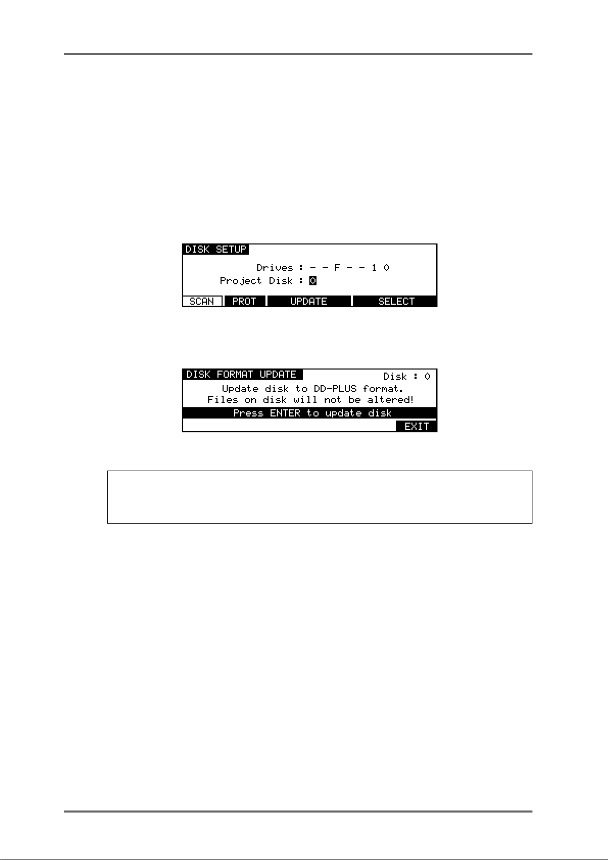
DISK P AGES - 7
NORMAL AND EXTENDED FORMAT DISKS
T o prevent compatibility problems with many of the new features introduced in DD8 Version 2.0,
this version of software no longer directly supports writing to NORMAL or EXTENDED format
disks created on earlier versions of software. Although both these disk formats are still recognised
and fully supported for playback compatibility, any attempt to write to these disks will give an
error message saying “Disk Format Is Read-Only!”. EXTENDED format disks can be easily
updated to DD-PLUS format as described in the next section.
UPDATING EXTENDED FORMAT DISKS
When an EXTENDED format disk is selected on the DISK SETUP page, an extra UPDATE
softkey will appear:
Pressing UPDA TE will take you to the DISK FORMA T UPDA TE page which allows you to update
the current disk’s format from EXTENDED to DD-PLUS format.
To update the selected disk’s format, press the ENTER key.
NOTE : ALTHOUGH THIS PROCESS IS NON-DESTRUCTIVE (EXISTING FILES ON THE
DISK WILL NOT BE ALTERED), ONCE THE DISK IS UPDATED, IT CANNOT BE READ ON
EARLIER VERSIONS OF DD-SERIES SOFTWARE THAT DO NOT RECOGNISE THE DDPLUS FORMAT!
Page 30 DD8
plus
Version 2.20 - September 1998
Page 41

DISK P AGES - 7
CLEANUP DISK
Pressing CLEAN (F3) in the main UTILITIES page will take you to the CLEANUP DISK page
which allows you to clear out redundant recordings and so save valuable disk space. Pressing
F3/CLEAN shows this screen:
It is possible to have a disk full of unreferenced audio files. These are pieces of audio that have
no association with any project. These are usually created when recording. For example, you
make one recording and make a mistake. You drop in again over that, recording a new piece of
audio. If the original recording is not in another project, the audio associated with the original cue
you recorded of it has become ‘unreferenced’ and is taking up disk space needlessly . Of course,
if you keep recording over and over again on the same spot, you can fill your disk up fairly
quickly. Also, if you delete a cue from a project via an appropriate remote, you can end up with
unreferenced audio. The functions in the CLEANUP page allow you to deal with this.
The CLEANUP functions are:
CLEANUP
This will only erase unreferenced audio but will not ‘top and tail’ the cues that are valid. However ,
because CLEANUP keeps all the audio that may be being referenced (no matter how small),
you may see no change or only a small change in the FREE ON DISK field because unlike
MINIMISE, if just one cue in one project uses one second of a ten minute recording, the whole
ten minutes will be kept. If you need to free up a further nine minutes and 59 seconds, use
MINIMISE.
Pressing CLEANUP will give this message:
Because audio may be being referenced by an EDIT CLIPBOARD (if the disk has been edited
via an appropriate remote or used by DD1500/DR8/DR16), you could try a cleanup and end up
with no appreciable increase in available disk space. This option allows you to select whether
you want the clipboard to be deleted as well. You should make your choice using F5 or F6 as
appropriate.
Next, you will be given a final safeguard prompt:
When performing a cleanup, you should be aware that it is possible to have a project on a
removable disk but for the audio for that project to exist on another disk (maybe the project is on
an MO but the audio associated with it is all on a fixed hard disk). If the removable ‘project’ disk
is not present on the system when you perform a cleanup, you run the risk of losing all the audio
for that project. The reason is simple...
The CLEANUP function works by searching all the projects on all the disks currently attached to
the system and it establishes what audio is being used by those projects and what is not. It then
deletes any audio NOT being referenced by those projects from the disks.
plus
Version 2.20 - September 1998
Page 31DD8
Page 42

DISK P AGES - 7
If the audio associated with a project on a removable disk is on another hard disk and the
removable disk is not in the system when you run CLEANUP, what will happen is that the DD8
will search through all the projects it can find on the system in order to establish what audio
should be kept and what should be deleted. Of course, it won’t find the removable disk because
it is missing and so assumes that all the audio that it has found on the hard disk(s) related to the
project on the removable (which is missing, of course) is unreferenced and will therefore delete
it. When you come to insert the removable disk and try to play it, it will show that all the audio
associated with it is missing and the project will be rendered unplayable.
Press EXIT (F6) to abort or , if you are sure you can proceed safely and no disks are missing from
the system, press ENTER but...
BE VERY CAREFUL BEFORE PROCEEDING AS YOU MAY IRRETRIEVABLY DESTROY
During the cleanup process, the bottom of the LCD will show:
The cleanup process will delete all unused audio on any disk connected to the system. Depending on the amount of unused audio, this could take a while so do this is in a quiet moment!
A PROJECT ON A REMOVABLE DISK MISSING FROM THE SYSTEM.
NOTE: If all this looks a bit worrying, our apologies but these prompts are provided to safe-
guard against you accidentally losing valuable data. The fact is that there is no good reason
why you should have your project on one removable disk and all the audio associated with it
on another and it is a practice that should be avoided. Presumably, the reason a removable
disk is used is so that it can be taken elsewhere for playback. If all the audio exists on another
disk, then it won’t play anywhere else successfully.
MINIMISE
This will also erase any unreferenced audio on the disk but will also ‘top and tail’ the recordings,
discarding any audio that is not actively referenced to any project and/or library . This is the most
efficient cleanup routine as it gets rid of ANY audio not being used leaving you only with the
audio that is actually relevant to any projects and/or libraries on disk(s). Pressing MINIMISE will
give this prompt:
Because the DD8 has to go round and top and tail every piece of audio affected by the MINIMISE
function, it can take a long time. After that, it has to ‘fix up’ all the cues that have been affected
in all the projects/libraries and this will also take time. The exact length of time, of course, depends on the amount of audio being minimised but it is recommended you do this at the end of
the day, maybe even leaving it to run overnight!
** IMPORTANT **
The MINIMISE function cannot be aborted once you have started it.
* DO NOT, UNDER ANY CIRCUMSTANCES, SWITCH THE DD8 OFF DURING MINIMISE
*
IN THE EVENT OF ACCIDENTALLY PROCEEDING WITH THE MINIMISE FUNCTION
AND THEN CHANGING YOUR MIND, ONCE THE PROCESS HAS STARTED, IT WILL
HAVE TO BE LEFT TO CONTINUE THROUGH TO THE END.
SWITCHING THE DD8 OFF DURING THE MINIMISE PROCESS WILL CAUSE IRREPA-
RABLE DAMAGE TO YOUR DATA!!
Page 32 DD8
plus
Version 2.20 - September 1998
Page 43

DISK P AGES - 7
Pressing ENTER will cause this prompt to be displayed:
As described above, because it is possible for projects and audio to exist on separate disks, if a
project disk is missing from the system, you may cause data to be lost if a disk is missing from
the system. Please see the explanation given in CLEANUP regarding this and please proceed
with caution.
plus
Version 2.20 - September 1998
Page 33DD8
Page 44

DISK P AGES - 7
BACKING UP TO SCSI TAPE DRIVES
As disks become full or projects get finished, you need some way to backup the material for safe
keeping so that, if needs be, you can come back to it at a later date. Y ou could, of course, simply
copy it all off to another disk of some form but this can be an expensive way of doing it.
A more cost ef fective method is to backup to some form of tape medium and the DD8 allows you
to backup the contents of your disk(s) to SCSI tape drives via the SCSI-A connection. This
function is accessed by pressing BACKUP (F4) in the DISK UTILITIES page.
In the main UTILITIES page, when you press BACKUP (F4), you will see this screen::
The Disk key (F1) is used to move the cursor to the DISK ID field. The Tape key (F2) is used to
move the cursor to the SCSI Tape ID field.
Disk ID This selects the disk that will be backed up to the SCSI tape drive.
SCSI Tape ID This selects the SCSI ID of the tape drive.
The RESTORE key (F4 or F5) will take you to pages where you can reload data previously
backed up to SCSI tapes.
When you press the BACKUP key (F3), you will be taken to this screen:
Before we look at the actual functions, an understanding of SCSI tape drives is in order.
SCSI tape drives can be regarded as slow, linear disk drives. A single tape can contain several
backups. However, whereas a disk drive has just the one directory where information relating to
the data on the tape is stored, a tape drive has a directory for each backup on the tape.
Of course, you may find it easier to keep track of backups by backing up each disk/project to its
own SCSI tape (i.e. one tape will contain only the contents for one backup) but you may, if you
wish, make several backups to one tape and then restore them individually by name if you
prefer.
FORMATTING A TAPE FOR BACKUP
Before you can perform a backup, you must first format the tape so that the tape is set up to
receive files and digital audio data. This is done using the FORMAT key.
To format the tape, first select the appropriate SCSI ID for the tape drive in the SCSI BACKUP
FUNCTION page. As with disk drives, the tape drive must not share the same SCSI ID as any
other SCSI device on the buss. Once selected, go to the SCSI BACKUP page and press the
format key(F3). You will see this screen:
Page 34 DD8
plus
Version 2.20 - September 1998
Page 45

DISK P AGES - 7
** FORMATTING THE TAPE WILL PERMANENTLY DESTROY ITS CONTENTS **
PLEASE BE CAREFUL BEFORE PROCEEDING
Because of the potential danger of accidentally formatting an existing tape, you must press YES
(F5) to proceed. During the format, you will see the message “FORMATTING TAPE. PLEASE
WAIT” pop up on the screen during the process. Once the process is complete, you will see the
message “FORMAT COMPLETE”. The tape is now ready for use.
NOTE 1: The format should not take long under normal circumstances (15 seconds or so) but
if the tape has been used several times before, you may find it takes longer as the DD8 may
need to check the tape to make sure it is suitable for use. Under extreme circumstances, it
may need to check the entire tape and so could take some time. If this is the case and the
formatting seems to be taking a long time, you can press ESCAPE to abort the formatting
process.
T o avoid this, it is recommended you always use new , unused tapes. It is also not a good idea
to use tapes that may have been used to backup material from some other system (for example, a PC or a Macintosh™ computer or (heaven forbid!) some other disk recorder.
NOTE 2: If you receive other messages such as DRIVE NOT READY or DRIVE BUSY, then
there is a problem with the cable and/or the drive. Please check both. Is the drive switched
on? Is there a tape in the drive? Are the cables connected securely? Is the SCSI buss terminated correctly? If everything seems correct but the problem persists, try moving the tape
drive elsewhere in the buss (i.e. move from the end of the chain to the middle or vice versa).
If the problem still persists, contact your AKAI professional dealer.
If a message such as THE SELECTED SCSI ID IS A DISK DRIVE is shown, this indicates you
have selected the wrong SCSI ID in the SCSI T APE field. Please take the appropriate steps.
plus
Version 2.20 - September 1998
Page 35DD8
Page 46

DISK P AGES - 7
The fields on the SCSI BACKUP page are:
TITLE Y ou may give the backup a title of up to ten characters. This will be stored
NOTE: As with any SCSI device, the tape’s SCSI ID should be unique and should not share
the same ID as another device on the SCSI buss.
BACKUP TYPE This selects what will be backed up to the SCSI tape. You may select:
in the SCSI tape’s directory and you will be able to use this name to
selectively restore the backup in future if you have archived several different backups to the same tape. When you move the cursor to this field
by pressing the Title key (F1) the screen will change to allow a new name
to be entered. If you do not specifically give it a name, the default name
BACKUP will be used.
SELECTED FILES Y ou may , via F5 (SELECT), select specific files
to backup.
ALL PROJECTS Y ou may backup all the projects on the selected
disk.
ALL LIBRARIES Y ou may backup all the libraries on the selected
disk.
ALL PROJS & LIBS You may backup all the projects and all the li-
braries on the selected disk.
ENTIRE DISK You may backup everything on the disk.
BACKING UP SELECTED FILES
Choosing SELECTED FILES in the BACKUP TYPE field will show this screen:
To actually select the files, press SELECT (F5). You will see something like this screen:
Y ou can select PROJECT or LIBRARY in the TYPE field, You may select a disk to backup in the
DISK field.
Press the File key (F2) to move the cursor to the list of files. To select the file you wish to backup,
move the cursor to the file name and press the SELECT key (F4/F5). A small block appears to
the left of the file name to indicate it is selected for archiving. For example:
Page 36 DD8
plus
Version 2.20 - September 1998
Page 47

DISK P AGES - 7
In this case, PROJECT 1 is selected for backup. The left hand side of the LCD will show how
many files are selected. In this case, just one.
Y ou may also select several files for backup in this way . As in other disk pages, arrows appear to
indicate files that are ‘off-screen’. Use the DATA +/- keys to scroll through the list.
Files selected by mistake can be de-selected by pressing the SELECT key (F4/F5) a second
time.
Once you have selected the file(s) you want to backup, press EXIT (F6) to return to the main
SCSI BACKUP page and proceed with the backup.
BACKING UP ALL PROJECTS AND/OR LIBRARIES
If you have selected ALL PROJECTS, ALL LIBRARIES or ALL PROJS & LIBS, all you need to do
is press the ENTER key. All the projects and/or libraries on the disk selected in the DISK ID field
will be backed up. If any projects and/or libraries use audio from any other connected disks,
these too will be backed up to the destination SCSI tape.
The exact amount of time the backup will take depends on the amount of material being backed
up. Backup speed is approximately five times real-time (i.e. ten minutes of audio will take approximately 2 minutes to backup).
BACKING UP AN ENTIRE DISK
As well as selectively backing up chosen files or backing up all projects and/or libraries, you may
also make a duplication of the disk by selecting ENTIRE DISK in the BACKUP TYPE field.
NOTE: Although ENTIRE DISK may seem the same as ALL PROJS & LIBS, there is a difference. ALL PROJS & LIBS will backup everything from the selected disk but it will also backup
any audio from other disks that are used in the projects and/or libraries being backed up. ENTIRE DISK, on the other hand, only backs up the audio on the selected disk, not any audio
referenced on other disks. ALL PROJS & LIBS, therefore, is more suitable for backing up your
work whilst ENTIRE DISK is a better selection to make if you just want to make a safety copy of
a disk.
PERFORMING THE BACKUP
Regardless of the backup type you have selected, to actually perform the backup, simply press
the ENTER key. You will then see this screen:
Here, the DD8 is getting the tape ready for the backup. First of all, it will look at the tape’s
directory to make sure that there is no backup of the same name. If a backup of the same name
exists on the tape, you will receive this message:
In this case, press ABOR T and give the backup a new name and try again (i.e. press ENTER) or
insert a new tape and press CONTINUE.
NOTE: You will need to specifically go to your tape drive and use the front panel EJECT key
to eject the current tape and insert a new one.
plus
Version 2.20 - September 1998
Page 37DD8
Page 48

DISK P AGES - 7
Assuming everything is OK, the DD8 will then wind the tape to the first available space where it
can write data. If the tape is a new, freshly formatted tape, this will be quite quick but if the tape
contains several backups already and these contain a lot of data, it may take a while to wind to
the first available area of the tape suitable for backing up to.
NOTE: You may see other messages pop up. These will be momentary - don’t worry about
these.
Once a suitable position on the tape has been located, the backup will begin and you will see
something like this screen as the backup takes place:
The screen shows the progress of the backup as it takes place and this is expressed as a
percentage and as a highlighting bar. The percentage in the top line shows how much of the
individual file has been backed up whilst the percentage in the bottom line shows how much of
the entire backup has been done.
If any of the selected files use audio from any other connected disks, these too will be backed up
to the destination SCSI tape (except in the case where ENTIRE DISK is selected). During the
process, you may abort the backup by pressing the ESCAPE key at any time.
The exact amount of time the backup will take depends on the amount of material being backed
up. Backup speed is approximately five times real-time (i.e. ten minutes of audio will take approximately 2 minutes to backup).
At the end of the backup, you will see this screen:
The DD8 will rewind the tape to the start in readiness for the next backup. Exactly how long this
takes depends on the amount of data on the tape.
Finally, you will see this screen display:
Press any key to continue.
Page 38 DD8
plus
Version 2.20 - September 1998
Page 49

DISK P AGES - 7
VERIFYING A BACKUP
Once you have performed a backup, you may like to verify it to check that everything has backed
up correctly. This is done by pressing the VERIFY key. You will see this screen:
Y ou should press YES (F5) to continue, NO (F6) to abort. As the verification takes place, you will
see this screen:
You may abort the process at any time by pressing the ESCAPE key.
NOTE: The VERIFY process does a comparison of what is on the source disk and what is on
tape and the idea is that the disk contents and the tape contents must be identical for the
verification to be successful. Because of this, the VERIFY process is best done immediately
after a backup. In this case, you should have no problems as the two media should have
identical contents. If, however, you make a new recording on the source disk or delete anything from the source disk after the backup, the contents of both media will not be the same
and so you will receive messages such as “FILE XXXX MA TCH NOT FOUND”. This is telling
you that either it has found something on the disk which does not correspond to what is on
tape (i.e. you may have made a new recording) or it has found something on tape which it
cannot find on the disk (i.e. you have maybe deleted something off disk).
It is not essential that you run the VERIFY process after a backup but, bearing in mind the
potentially serious implications of a faulty backup, it is highly recommended. However, you will
please note that the VERIFY process will take about two or three times as long as the backup
took so whilst it’s recommended you verify your backups, you might like to do it during a ‘quiet
moment’.
plus
Version 2.20 - September 1998
Page 39DD8
Page 50
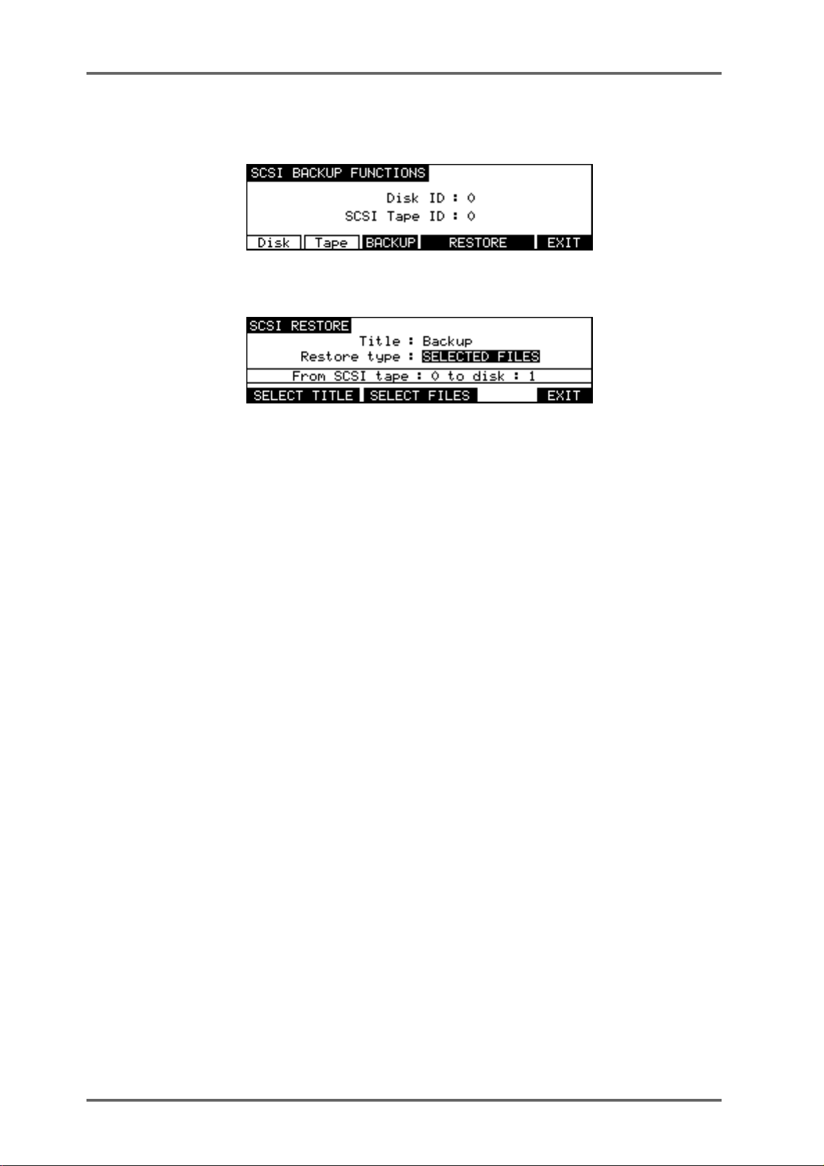
DISK P AGES - 7
RESTORING A BACKUP
To restore data, in the DISK UTILITY page press BACKUP. You will see this screen:
Select RESTORE (F5/6). You will see this screen:
As you can see, this is basically the reverse of the SCSI BACKUP page. The fields are:
TITLE Shows the name of the backup you wish to restore.
RESTORE TYPE Selects what will be restored to the disk.
FROM SCSI TAPE Shows the tape drive the data will be restored from.
TO DISK Shows the disk the data will be restored to.
Page 40 DD8
plus
Version 2.20 - September 1998
Page 51

DISK P AGES - 7
PERFORMING A RESTORE
To perform the restore, first select the disk you wish to restore to and the SCSI ID for the tape
drive in the SCSI BACKUP FUNCTIONS page.
Y ou need to enter the name of the backup you wish to restore. In the simplest example, the tape
you are restoring from may contain just one backup that uses the default name BACKUP. In this
case, you can just press ENTER to start the restore. If a name other than the default was used,
press SELECT TITLE (F1/F2) to see the names of the backups on the tape. Pressing SELECT
TITLE will show this screen:
Depending on the number of backups on the tape, it could take a while to search the tape for the
different titles. If it contains only one backup, the search should not take long but search time will
increase according to the number of backups on the tape. Press YES (F5) to continue. You will
see this screen:
After a while, you will see this screen:
Here, you see a list of all the backups on the tape and the number of files (cues/clips) contained
within them. In this case, there are just three backups. If more than five backups exist on the
tape, up/down arrows will appear to indicate that there are items ‘off screen’ that you may select.
Use the DATA +/- keys to move the cursor to the one you want to restore and press ENTER. The
backup will be selected and you will be taken back to the main SCSI RESTORE page:
The easiest restore to perform is when a tape has just one backup on it. In this case, simply
select ALL PROJS & LIBS and press ENTER. Regardless of the type of backup you performed
on this tape, any projects and libraries found on the tape will be restored.
Similarly , if the tape contains just one backup of only libraries, you can still use the ALL PROJS
& LIBS selection - if the DD8 doesn’t find any projects, it will ignore this and will restore only the
libraries it finds. The same would be true of projects. If the tape only contains projects, even
though ALL PROJS & LIBS is selected as the restore type, if it can’t find any libraries, it will just
continue, restoring only the projects.
plus
Version 2.20 - September 1998
Page 41DD8
Page 52

DISK P AGES - 7
You can also select ENTIRE BACKUP as the restore type and this will restore everything in the
selected backup.
Y ou may also select to restore only libraries by selecting ALL LIBRARIES. In this case, even if a
backup contains projects, these will be ignored. Likewise, if you select ALL PROJECTS, only
projects found will be restored and any libraries in the backup will be ignored.
Y ou may also specifically select the files you want to restore by selecting SELECTED FILES. To
actually select the files for restore, press SELECT FILES (F3/4). First, you will see this screen:
The DD8 needs to read the directory on the tape to know what files are contained in it. Press
YES (F5)to proceed (or F6/NO to cancel). You will see this screen:
Depending on the complexity of the backup, after a short while, you will be taken to something
like this screen:
Here, you may select the files in the backup you wish to restore (if you have used SELECTED
FILES as the backup type, you will already be familiar with this and operation is the same). Move
the cursor to the file you wish to restore and press the SELECT key. A small block will appear
alongside the filename to indicate that it has been selected:
The number of files selected for restore will be shown. Continue to mark the files you wish to
select in this way. Press EXIT (F6) to return to the main SCSI RESTORE page.
Page 42 DD8
plus
Version 2.20 - September 1998
Page 53

DISK P AGES - 7
Regardless of the type of restore you have selected1, the process is initiated by pressing the
ENTER key. You will see this screen display:
Followed by this screen:
After a short while (depending on how many cues are in the backup), you will see this screen:
Y ou will see the backup being restored onto the selected disk. The percentage figures will change
as the restore progresses and highlighted bar will move across the bottom of the LCD to further
indicate progress.
You will then see this display:
What the DD8 is doing here is ‘fixing up’ all references to the audio data that has just been
restored so that any projects and/or libraries that may use the cues/clips that have just been
restored will play correctly . The percentage will change to indicate progress and the exact length
of time it takes depends on the mount of ‘fixing up’ the DD8 has to do (i.e. how many different
places the audio you have restored is used).
Finally, you will see this screen display:
1 There is a difference when ENTIRE BACKUP is selected. This will be explained later.
plus
Version 2.20 - September 1998
Page 43DD8
Page 54

DISK P AGES - 7
If, when you perform the restore, a library or project on the disk you are restoring to shares the
same name as one being restored, you will see this prompt:
If you press NO (F4), the restore will proceed as described on the preceding page but a new
project or library will be created with a new automatically numbered name. Using the above
example, pressing NO at the OVERWRITE prompt would create a new library called ANIMALS
1 (or some other suitably numbered library of that name).
Pressing YES (F5/6) will cause the restore to proceed as normal and as described on the previous page and the selected library on disk will be overwritten.
**Be careful that you don’t overwrite a valuable project **
There is no means to retrieve it once it has been overwritten.
Pressing ABORT (F3) will abort the whole restore process. You will see this screen:
Page 44 DD8
plus
Version 2.20 - September 1998
Page 55

DISK P AGES - 7
RESTORING THE ENTIRE BACKUP
Restoring an entire backup is essentially the same as the other types of restore except that
when you press ENTER, you are prompted thus:
You have the option to completely wipe the selected disk prior to restoring data back onto it.
Respond by pressing NO or YES as appropriate (or ESCAPE to abort).
*** BE VERY CAREFUL WITH YOUR SELECTION ***
If you select YES, the data you erase cannot be retrieved or salvaged.
plus
Version 2.20 - September 1998
Page 45DD8
Page 56

DISK P AGES - 7
NOTES ABOUT BACKUP/RESTORE
When backing up data to disk, there are a few things you should be aware of.
• When ALL PROJECTS, ALL LIBRARIES, ALL PROJS & LIBS, SELECTED FILES and ENTIRE DISK are selected as the BACKUP TYPE, if any projects and/or libraries use audio
from other disks, this audio will also be backed up. However, when you come to restore this
data, the material from the other disks will be restored to the single ‘destination’ disk selected in the TO DISK field. For example:
ID#0
ID#1
ID#2
ID#1
ID#2
SFX
MUSIC
DIALOGUE
Tape Drive
DD8
BACKUP
SFX, MUSIC and DIALOGUEID#0
Tape Drive
DD8
RESTORE
In the above example, SFX, music and dialogue from disk IDs 0, 1 and 2 are backed up to
tape but these will be restored to the disk selected in the RESTORE TO field (in this example, Disk ID#0)
In other words, you should ensure that the destination disk for the restore is large enough to
accommodate all the material (the DD8 will inform you if it isn’t).
• If the data you are trying to backup to tape is larger than that which the tape can hold (or if
there is already quite a bit of data on the tape), the backup will be done across two or more
tapes. The DD8 will prompt you if this is the case and will tell you to insert another tape. If
the tape is unformatted and unsuitable for use, you will be prompted to format the tape
whereupon the backup will continue.
Of course, there is nothing wrong with this practice but it may get awkward trying to keep
track of your backups and so, in view of this, to avoid this situation, you might prefer to use
new, freshly formatted tapes when attempting a backup.
Page 46 DD8
plus
Version 2.20 - September 1998
Page 57

DISK P AGES - 7
SUGGESTIONS FOR BACKUP/RESTORE
• Try not to re-use tapes. They are relatively inexpensive to buy and potentially carry very
expensive data so it is not wise to economise.
• Do not use ordinary audio tapes unless you’re really stuck as tapes made specifically for
backup will be more reliable.
• Try to organise your backups sensibly to make restoring them easier.
• In much the same as in ‘the old days’ of 1/4 inch and multi-track tapes, try to ensure that the
tape box is well labelled. Include any relevant information regarding the data stored on it.
Include dates, client names and anything else you think appropriate that will make recognition of the material and the restore that much easier. Remember! It might not be you who
restores it but somebody completely unfamiliar with the data.
• Store and treat the tapes carefully. Just because the media is small doesn’t mean it doesn’t
deserve the same respect as a hefty 10” reel of master tape.
• Naturally, keep backup tapes away from magnetic sources such as monitor speakers, etc..
• If you have to send the backups anywhere, make a copy of them first.
• When sending tapes anywhere, package them well in a suitable padded envelope or box
and wrap the tape in aluminium foil to help prevent damage from stray magnetic interference.
• Always write protect the tape. It may be a nuisance should you try to backup to it and get an
error message but this is better than accidentally formatting it or overwriting existing backups.
• If you are travelling abroad with your backups, take them as hand luggage. Although the Xray machines are supposed to be safe, you may be able to persuade airport security to have
them manually inspected (normal luggage is often subjected to high power X-ray inspection
that may not be too kind on the tape). Leave a copy at home just in case.
• Keep backups away from liquids, etc..
• Do not leave tapes lying around in vehicles, especially on hot days.
plus
Version 2.20 - September 1998
Page 47DD8
Page 58

DISK P AGES - 7
TAKING CARE OF YOUR TAPE DRIVE
Tape drives need to be taken care of quite carefully. You should refer to your drive’s operator ’s
manual for more details on this but some general guidelines are:
• As routine maintenance, the heads should be cleaned after every 25 hours or so of use.
Basically, clean the heads regularly.
• To clean the heads of your drive, only use the head cleaner recommended in your drive’s
documentation.
• If your drive is a SCSI DAT drive, do not use standard audio DAT head cleaners.
• If you are using a SCSI DAT drive, avoid using audio DATs. Use only those tapes recommended by your drive’s manufacturer.
• Keep the drive in a dust free environment. Dust on the heads could lead to a loss of data
integrity and failed backups/restores.
• Don’t smoke near the tape drive. This can really clog the heads!
• Do not try to use the tape drive if you move it from environments of differing temperatures
and humidity. Moisture on the head as a result of condensation could damage the tape. If
you must move the drive from one place to another, turn it on and leave it for a while before
attempting to use it to give any condensation a chance to evaporate. Consult your drive’s
operator’s manual for details on this.
• If you must manually eject the tape, there can be a few seconds delay before the tape is
ejected. Do not power down the drive in this period as you may damage the heads and/or
the tape.
Also, don’t forget to pay attention to the normal considerations of SCSI:
• Make sure the total length of the buss doesn’t exceed 6 metres.
• Make sure the correct devices are terminated (this should be the first and last in the chain
with all other being unterminated).
• Make sure that no devices on the buss share the same SCSI ID.
Etc..
Page 48 DD8
plus
Version 2.20 - September 1998
Page 59

DISK P AGES - 7
COPYING DISKS
Selecting COPY (F5) on the DISK UTILITIES page goes to the Disk Copy screen which allows
files to be copied from one disk to another.
The parameters are:
FROM DISK Pressing F1 (From) will move the cursor to the ‘From disk’ field where you
may select the ‘source’ disk you are copying from.
TO DISK Pressing F2 (T o) will move the cursor to the ‘to disk’ field where you may
select the ‘destination’ or ‘target’ disk you are copying to.
COPY TYPE Pressing F3 (Type) will move the cursor to the ‘copy type’ field where you
may select the type of copy operation. You may select:
SINGLE FILE - this will copy a specific file as selected on the COPY FILE
page.
ALL PROJECTS - This will copy all projects on the source disk to the
destination disk.
ALL LIBRARIES - This will copy all the libraries on the source disk to the
destinations disk.
DUPLICA TE DISK - This will copy everything from the source disk to the
destination disk.
IMPORTANT NOTE: DUPLICATE WILL FIRST ERASE THE DESTINATION DISK BEFORE
DUPLICATING THE SOURCE DISK TO IT.
NOTE: It is not possible to copy from a disk to itself (i.e. from disk 0 to disk 0). Y ou will receive
the prompt: DISK CAN’T BE COPIED TO ITSELF!
If SINGLE FILE is selected as the copy type, soft keys F4/F5 will change to show SELECT FILE.
Pressing either of these keys will take you to the COPY FILE screen where you can select the
file to copy.
Press Type (F1) to select the type of file you wish to copy (PROJECT or LIBRARY). Press File
(F2) to move the cursor to the file list to and the file you want to copy using the DATA+/- keys.
Pressing COPY (F4/F5) on the COPY DISK page, or COPY FILE (F4/F5) on the COPY FILE
page, initiates the COPY process. During the copying process, the bottom line of the LCD will
show something like this display:
plus
Version 2.20 - September 1998
Page 49DD8
Page 60

DISK P AGES - 7
A highlighting display will move across the bottom of the LCD as the file is copied. The copying
process is approximately 2-4 times faster than real-time (i.e. a 12 minute piece of audio will take
between 6 and 3 minutes to copy). The time it takes to copy depends on the speed of the disks
you are using (i.e. MO to MO is going to take longer than a hard disk to hard disk copy) and the
nature of the files you are copying (e.g. one single 12 minute piece of audio is likely to get copied
faster than 48 x 15 second cues).
At any time, you may press the ESCAPE key to abort the copy and the whole process will be
cancelled.
NOTE: In order to prevent you having an incomplete project on the destination disk, the
project selected for copying is erased from the destination disk along with all associated audio
when you press ESCAPE. This may take a second or two.
The same process is used for disk duplication.
You may leave the COPY DISK page at any time by pressing EXIT (F6).
The COPY process copies the project/library and all referenced audio across to the target
disk. This is to prevent audio becoming detached from the project or library with which it is
associated. However, the copying process only copies across the audio associated with the
cues plus a 10% ‘handle’ either side of the cue.
**IMPORTANT NOTES REGARDING COPY **
For example, imagine that you have a 5 minute continuous recording of assorted sound effects and you have used a mere 30 seconds of it in a project you have chosen to copy . On the
source disk, that cue is referencing the full 5 minutes of audio (but only playing the relevant 30
seconds of it in the project). When you copy the project across, it will only copy the 30 second
section you are using in the project (plus a 3 second ‘handle’ either side) NOT the full five
minute piece of audio it originally came from. You may find therefore, that when you copy a
project from one disk to another, the project on the target disk will use less disk space than the
one on the source disk.
owever , please note one important restriction regarding copying individual projects and libraries separately to another disk. Because the audio is copied each time you individually copy a
project or a library , this will take up extra disk space on the destination disk. This will happen
even when you copy two similar projects that reference the same audio.
For example, imagine you have two projects PROJECT 1 and PROJECT 2 on DISK 0 and
both projects use exactly the same audio (PROJECT 2 being just a slight variation on PROJECT
1). If you were to select SINGLE FILE as the file type and individually copy each project to
DISK 1 separately , you will find that the audio is duplicated, using up disk space. In this case,
you should use ALL PROJECTS - this would copy both projects but would only copy the audio
once.
In the event of you having, say , five projects on DISK 0 all using the same audio but you only
want to copy PROJECT 1, 2 and 5 to DISK 1, select ALL PROJECTS and copy all five projects
across in one operation (and hence only one version of the audio) and then, on DISK 1, delete
projects 3 and 4.
If the destination disk has a file of the same name as the source disk when copying, it will
prompt you to overwrite the existing file or not.
The same is true when copying libraries.
Page 50 DD8
plus
Version 2.20 - September 1998
Page 61

DISK P AGES - 7
MACINTOSH DISK COMPATIBILITY
The DD8 is able to read and write certain files to Macintosh HFS format disks. When a Macintosh
HFS format disk is selected from the DISK SETUP page, you will see the following screen:
Pressing TYPE (F1) will move the cursor to the file type field where you can select the type of file
you want to load. The current options are:
OMF To load an OMF (Open Media Framework) file allowing playback of audio created
with systems such as Avid AudioVision or MediaComposer
PT 3.2 To load a 16-bit Session file created on a Digidesign “Protools 3.2” system.
PT 4 To load a 16-bit Session file created on a Digidesign “Protools 4” system.
PT 24 To load a 24-bit Session file created on a Digidesign “Protools 24” system.
ALL FILES To view all files on the selected disk. This may be used to select any OMF files
that are not recognised by the DD8. This may occur if the OMF file was created
on a non-Macintosh system.
NOTE: Due to the limited screen size, the DD8’s LCD does not show the individual folders on
the disk that would normally be shown on a Macintosh screen. Instead, the display shows a
list of all files of the selected type on the disk. In practice, most disks will only contain a few
‘project’ files and a large amount of audio, so it should be relatively easy to find the required
file.
Pressing NEW (F5) will take you to the NEW PROJECT page where you can create new Protools
Session files on the Macintosh disk. When a new Session file is created, a folder with the new
Session’s name will be created at the root level of the selected disk. The new Session file is
placed inside this folder together with folders for Audio Files and Fade Files. All SD-II or AIFF
files recorded into this Session will be placed into the folder labeled ‘Audio Files’.
plus
Version 2.20 - September 1998
Page 51DD8
Page 62
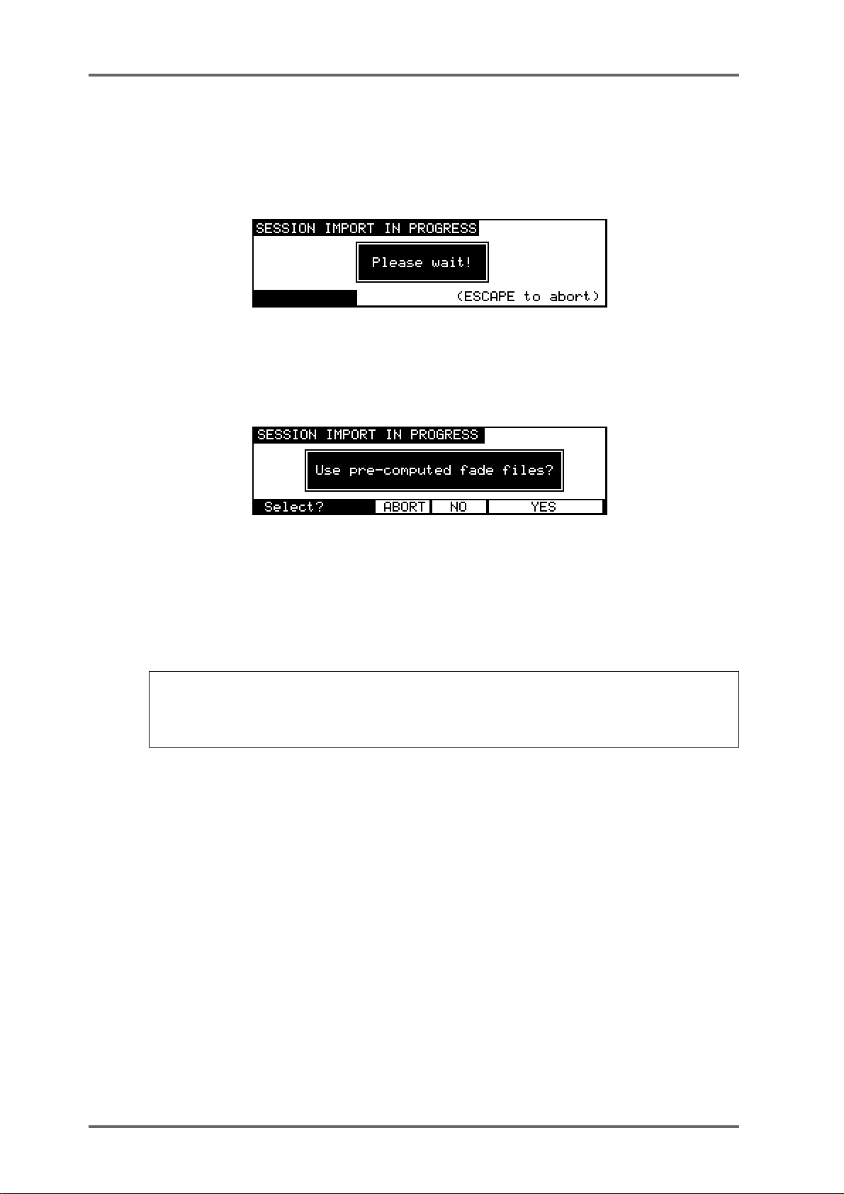
DISK P AGES - 7
PROTOOLS IMPORT
After moving the cursor to the required Session file, press the LOAD soft key (F6) to import the
file. The display will change to show the following screen and the progress bar at the bottom of
the screen will indicate that the file is being imported.
As part of its normal operation, Protools renders all fade files as separate audio files on disk.
When a Protools Session containing fades is loaded into the DD8, you will be given the option to
use the precomputed files or replace them by real-time fades for playback:
If you select YES, the DD8 will load and playback all fade-regions from the rendered fade files on
disk. If you have created any custom fades in Protools, you should choose this option to ensure
the DD8 plays back the file correctly.
If you select NO, the DD8 will perform real-time fades in each fade region. This option will give
the best performance from the DD8 (as there will be less disk activity) and will also allow easier
editing of the Session if you are using a DL1500 remote controller.
NOTE: Some systems that create Protools Session files (including Digidesign’s “OMF Tool”.
and the DD8 itself) do not actually render fade files. If Session files from these systems are
loaded into the DD8 with the ‘use pre-computed fades’ option, the fade regions will not
contain any audio (and will be shown in yellow on the DL1500 ‘s VGA).
Page 52 DD8
plus
Version 2.20 - September 1998
Page 63
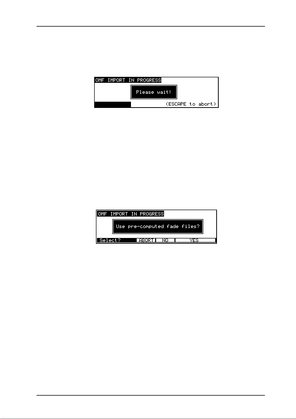
DISK P AGES - 7
OMF IMPORT
After moving the cursor to the required OMF file, press the LOAD soft key (F6) to import the file.
The display will change to show the following screen and the progress bar at the bottom of the
screen will indicate that the file is being imported.
NOTES CONCERNING OMF IMPORT
If you are controlling the DD8 from a DL1500, you will notice that no envelopes (waveforms) are
shown on the VGA after an OMF import. This is normal as there are no envelope files on the
Macintosh disk! You can use the DL1500’s COMPILE function to copy all used audio from the
Macintosh disk to the Akai disk. During this process, envelope files will automatically be generated. Note that the PRE-READ function is driven from the envelope files, so it will not function
with projects imported from OMF files.
Some OMF files contain pre-computed (rendered) fades. If these are found while an OMF file is
being imported, you will see the following prompt which allows you to select if the pre-computed
fades are loaded as separate cues (by pressing YES), or if the fades should be replaced by realtime fades (by pressing NO):
AVID MEDIA-COMPOSER AND AUDIOVISION
Avid Media Composer and Audiovision provide options to allow several types of OMF files to be
created. When preparing OMF files for use on the DD8, you need to select the options for OMF
Version 1 and for “OMFI Composition with audio media”. This will create an OMFI file that contains the edit information as well as all copies of all of the associated audio in AIFF format within
the OMFI file.
plus
Version 2.20 - September 1998
Page 53DD8
Page 64

DISK P AGES - 7
UTILITIES PAGE
Pressing UTILS (F4) on the LOAD (FROM MAC DISK) page will take you to the UTILITIES
page for non-Akai disks:
Some files created by Macintosh applications may contain more than 8 tracks of audio. In this
case, you may which to use several DD8s to playback the audio with up to 8 tracks playing from
each machine. Pressing the TRACKS key (F3) on the UTILITIES page will take you to the
IMPORT TRACKS page which can be used to select the 8 tracks that will be imported:
Soft keys F1,F2 and F3 can be used to quickly select tracks 1-8, 9-16 or 17-24. Alternatively, you
can select an alternative combination of tracks to import by moving the cursor to the required
playback track field (using the track keys, 1..8) and using the DATA +/- keys to select the audio
track that will be imported from the OMF file. Press EXIT (F6) to return to the LOAD (FROM MAC
DISK) page.
Finally , on the UTILITIES page, if you want to select a different disk, press SETUP (F4). This will
take you back to the DISK SETUP page:
Page 54 DD8
plus
Version 2.20 - September 1998
Page 65

DISK P AGES - 7
WAVEFRAME DISK COMPATIBILITY
The DD8 is able to read project files created on Waveframe disks including those from the
Timeline MMR-8. When a Waveframe format disk is selected from the DISK SETUP page, you
will see the following screen:
Pressing TYPE (F1) will move the cursor to the file type field where you can select the type of file
you want to load. Normally , this should be left on PROJECT to view the available projects on the
disk. ALL FILES can also be selected to view a list of all the files on the disk.
As with Macintosh disks, you can select which tracks you want to load from the PROJECT using
the IMPORT TRACKS page (accessible via the UTILS on F4).
After selecting the project you wish to load, pressing LOAD (F5/F6) will start the import process
and the following screen will be shown:
plus
Version 2.20 - September 1998
Page 55DD8
Page 66

DISK P AGES - 7
FAIRLIGHT DISK COMPATIBILITY
The DD8 is able to read project files created on Fairlight MFX3-plus disks in RBF format (The
Fairlight MFX3-plus supports two types of native disk format, RBF and FLFS. Currently , the DD8
is only able to recognise RBF formatted disks). When a Fairlight RBF format disk is selected
from the DISK SETUP page, you will see the following screen:
Pressing TYPE (F1) will move the cursor to the file type field where you can select the type of file
you want to load. The Fairlight MFX3plus stores all the the information necessary to play a
complete project (including all audio and edit information) in a file with the suffix ‘.MT’. The
Fairlight MFX3-plus also allows a separate MDL (Media Description Language) file to be created
which contains all the information to play the audio in the current project. This is identified with
a ‘.DL’ suffix.
The DD8 always reads the MDL file rather than the Fairlight native project file, so it is necessary
to ensure that this file is always created before the disk is removed from the MFX3-plus system.
Normally , the TYPE field on the LOAD (FROM F AIRLIGHT DISK) page should be left on MDL to
view the available MDL files on the disk. ALL FILES can also be selected to view a list of all the
files on the disk..
As with other non-Akai disks, you can select which tracks you want to load using the IMPORT
TRACKS page (accessible via the UTILS on F4).
After selecting the MDL file for the project you wish to load, pressing LOAD (F5/F6) will start the
import process and the following screen will be shown:
Page 56 DD8
plus
Version 2.20 - September 1998
Page 67

DISK P AGES - 7
EXPORT PROJECT PAGE
The DD8 is able to convert projects created on one system into files playable on a different
system. Currently, the DD8 can export from any of the readable project types (i.e Akai, OMF,
Waveframe, Fairlight or Protools) to Akai or Protools files. As well as conversion of the project
file itself, this process includes conversion of all audio files into a suitable format (e.g from Akai
format referenced by an Akai Project to Sound Designer II files referenced by a Protools Session).
The Export function can also be used to create an Akai project on an Akai disk that references
special “Akai->Fairlight” audio files. These projects are intended for playback on Fairlight MFX3plus
systems that include Akai File Exchange support.
The EXPORT PROJECT page is accessed by pressing EXPORT (F3/F4) on the SA VE PROJECT
page.
The project to be exported will be the one that is currently loaded into memory.
Pressing DISK (F1) will move the cursor to the TO DISK field where you can select the SCSI ID
of the drive to which the project will be exported.
NOTE: The selected drive must have been previously formatted appropriately for the export
you wish to perform (e.g An export to a Protools Session must be made to a Macintosh HFS
format disk).
Pressing TYPE (F2) will move the cursor to the file type field where you can select the type of
project you want to export to. The current options are:
AKAI To export to an Akai project on an Akai disk referencing Akai audio files.
AKAI -> FAIRLIGHT T o export to an Akai project on an Akai disk referencing special Akai audio
files intended for playback on a Fairlight MFX3plus system.
PT 4 To export to a “Protools 4” Session file on a Macintosh HFS disk refer-
encing 16-bit Sound Designer II files.
PT 24 To export to a “Protools 24” Session file on a Macintosh HFS disk refer-
encing 24-bit Sound Designer II files.
plus
Version 2.20 - September 1998
Page 57DD8
Page 68

DISK P AGES - 7
During the export process, portions of audio will be discarded so that only audio that is actually
needed will be copied and converted. If you are familiar with the DL1500, you will notice the
similarity to the COMPILE function. In fact, you can use the DD8’s EXPORT function to export
an AKAI project to another AKAI project on a different disk! During this process, audio files will
be minimised - unused top and tails will be discarded and additionally, unused audio in the
middle of the source file will not be copied, thus creating multiple files:
Pressing HANDLE (F3/F4) will move the cursor to the Handle field where you can select how
much extra audio will be copied before and after the audio that is actually referenced in the
project. If the Handle is very large, it is likely that the source audio files will be copied intact
without being minimised.
SOURCE FILE
Cue 1 Cue 2
Cue 3
FILE 1 FILE 2
DD1000 DISK COMPATIBILITY
The DD8 uses the same disk format as the Akai DD1500, DR8 and DR16. Disks can be interchanged directly between any of these machines. Additionally, the DD8 can read and use disks
made on the Akai DD1000 and it is possible to play Qlists created on a DD1000 directly on the
DD81.
LOADING DD1000 QLISTS
When you select a drive that has a DD1000 disk in it, an extra soft key will be shown on the
DISK SETUP page when you press the DISK key.
To load a DD1000 Qlist, you should press the DD1000 LOAD key (F3/F4) to go to the LOAD
DD1000 QLIST page. The screen will show a list of DD1000 Qlists which you may load as
normal.
When the Qlist is loaded, the DD8’s project deals with overlapping cuts and track output assignments using two schemes. If cuts use different outputs (for example, a mixture of outputs A, B or
AB, the following track assignments will be used:
Page 58 DD8
plus
Version 2.20 - September 1998
Page 69

,
DISK P AGES - 7
DD1000
OUT A CUTS
OUT AB CUTS
OUT B CUTS
track 1 +2 (track 1 if mono)
track 1 + 2 (track 1 if mono)
track 3 + 4 (track 3 if mono)
DD8
If all the cuts use the same outputs (for example, all cuts are assigned to output A), the following
track assignments will be used on the DD8’s project. For example:
Track 1
Track 2
Track 3
Track 4
Mono cut
Stereo cut 1
Stereo cut 2 Stereo cut 3
New cut is played back overlapped
The cuts are assigned to tracks 1+2/3+4 in a similar way to the manner in which the DD1000
assigns cuts to voices. In other words, where cuts in a DD1000 Qlist overlap, whereas on the
DD1000 they will play correctly (owing to the DD1000’s ‘voice’ assignment), on the DD8, they
will be placed on adjacent tracks so as to play correctly.
SAVING PROJECTS TO DD1000 DISKS
When a DD8 project is saved to a DD1000 disk, a DD1000 Qlist of the same name is automatically created and saved to the disk in addition to the DD8 project itself. This allows you to play
simple projects created on a DD8 on a DD1000. The DD8 makes its best attempt to store cues
for playback on the DD1000. It starts at track 1 and then continues until all the tracks are stored
or all 256 DD1000 cues have been used up. After saving a project to a DD1000 disk from the
DD8, the next time this disk is used you can choose to load the DD8 project rather than the
DD1000 Qlist by pressing the SELECT key (F5/F6) on the DISK SETUP page.
WARNING: If you load a DD1000 Qlist into a DD8, work on it and then save it again on the
DD8 you will lose any FADE and MIDI events that may have been on the original and you will
lose all cut names.
PLAYING DD1000 DISKS CREATED ON A DD8 ON A DD1000
Some degree of backwards compatibility is also possible between the DD8 and DD1000 and
any DD1000 disks you have worked with on the DD8 may still be used on a DD1000.
Recordings can be made on the DD8 to a DD1000 disk in the usual manner (i.e. select a track
for record, press PLAY+RECORD) but the DD8 uses the following rules to decide whether a
recording is mono or stereo when recorded on a DD1000 format disk.
• Adjacent channel pairs of tracks enabled for record are recorded as DD1000 stereo takes.
• Non-adjacent and remaining channels are recorded as DD1000 mono takes.
REC ENABLE track = 2
1
REC ENABLE tracks = 2+3
2
REC ENABLE tracks = 2+4
3
REC ENABLE tracks = 2+3+4+5
4
2 = MONO
2 + 3 =STEREO
2 = MONO, 4 = MONO
2 + 3 = STEREO
4 + 5 = STEREO
NOTE 1: When recording in stereo, the first track of the pair is always assigned to the left
channel of the DD1000. For example, in example number 2 above, track 2 would be assigned
to the left channel and track 3 to the right.
plus
Version 2.20 - September 1998
Page 59DD8
Page 70
DISK P AGES - 7
NOTE 2: If two mono recordings are assigned to a stereo pair, it will not be phase coherent on
the DD1000.
When recording on the DD8 is finished, the DD8 stores extra cuts files and record settings to
allow this backwards compatibility.
You will also note the way DD1000 take names are created by the DD8. The ten-character take
names are formed as follows:
A The first four characters are the recording name
B These show the track number the recording was made on
C This is a unique identifier to create a totally unique take name
MULTIPLE DISK DRIVE SYSTEMS
The DD8 works with multiple disk drives very differently from the DD1000 (much better in fact!).
A problem with the DD1000 was that you had to make sure that a disk was in its original drive
before it would playback properly. This is because the SCSI ID is a part of the Qlist cue. For
example, if a cue is specified to play from drive ID#3 but the disk is placed in drive ID#5, it will not
play .
The DD8 uses a method based on each disk’s unique label. This means that the DD8 ‘learns’ the
actual SCSI ID when the project is loaded. Therefore, a disk can be placed in any drive and the
project will still playback correctly regardless of the SCSI IDs the drives may be. The following
illustrates the difference between the two methods.
A cue in a DD1000 Qlist says:
“Play [TAKE N] from the disk in the drive with the SCSI ID#X”
If it can find that take on the disk in the drive with ID#X, it will play the cue. If it doesn’t find that
cue on the disk in drive #X, it will not play it. Neither will it try to look for it on another drive
because it is specifically looking for it on that ID and no other.
The DD8, however, says:
“Play [TAKE N] from the disk with the unique label #XXXXXXXX”
DD1000 disks, however, do not have the concept of disk labels and so to overcome this, the
DD8 will automatically write a label to the DD1000 disk, thereby giving it something it can work
from given the above statement. In this way , it doesn’t matter which drive the disk is in - the DD8
is looking for the disk label, not the SCSI ID. It will find this and so it will playback correctly
regardless of the drive the disk is in.
NOTE: Please note that for the label to be written to the DD1000 disk, the write protect switch
must be off. If the disk is write protected, the label can’t be written. In this case, the DD8 uses
the same logic as the DD1000 (i.e. Play [TAKE N] from the disk in the drive with the SCSI
ID#X) and you will have to make sure that the disk is in the correct drive.
Furthermore, if a DD1000 Qlist has audio that exists on one disk only (as is invariably the case),
the DD8 assumes that the audio is on the same disk as the Qlist and so it will also playback
properly.
Page 60 DD8
plus
Version 2.20 - September 1998
Page 71

DISK P AGES - 7
However, please note the following restrictions when taking a DD1000 disk from a DD8 back to
a DD1000:
• When a converted DD1000 Qlist is saved as a project on the DD8, in the DD1000 Qlist that
is also created, the DD8 resets all the cues’ SCSI IDs to be the same as the drive it was
played from on the DD8 (i.e. if you played the project on drive #4, all the cues will be reset
to have a SCSI ID of #4). This means that the disk must be either be saved on an appropriately numbered drive on the DD8 or the disk must be used in a drive with the correct SCSI
ID when you take it back to the DD1000 or you must edit each cue separately in the DD1000.
• If the DD1000 Qlist’s audio comes from more than one disk, then the original situation
remains and the disks must be placed in the correct drive in order to playback correctly.
It must be said that this all sounds terribly complicated. The fact is, it is! However, this is included
to make the transfer of disks between the two machines as easy as possible. In the majority of
cases, you will have a simple 2- or 4-track Qlist on one DD1000 disk which you can take to the
DD8, work on it there and (assuming you don’t try to add a further 6 tracks of material!!) you can
take it back to the DD1000 and play it there. Only in the case where you may bring multiple disks
from a multiple drive DD1000 system to a multiple drive DD8 system should you need to concern yourself with the above.
plus
Version 2.20 - September 1998
Page 61DD8
Page 72

SYSTEM - 8
SYSTEM SETTINGS
Pressing the SYSTEM key takes you to the SYSTEM menus. These pages contain parameters
which set up the basic operation of the DD8.
As there are more menus than soft keys, F6 is used as a “MORE” key to scroll through the list of
Menus in groups of five.
In all the SYSTEM menus, soft key EXIT (F6) returns to the previous level.
When you leave the system pages after changing parameters you will see the following screen:
If you don’t want to save your changes, press DON’T SAVE (F5/F6). You can always save your
settings later by going back to the SYSTEM pages and pressing the SAVE soft key.
If you want to save the settings to disk with the current project, select WITH PROJECT (F3/F4).
If you want to save the settings to flash ROM (where they will become the default settings for
new projects created), select FLASH ROM (F1/F2).
DIGITAL SETTINGS
The DIGI key (F1) takes you to the Digital Settings menu :
SAMPLE RATE Pressing Rate (F1) moves the cursor to the Sample Rate field.
This sets the system’s sample rate. You may select 32kHz, 44.1kHz and
48kHz or any of the associated pull-up and pull-down frequencies (i.e.
44,056Hz):
Page 62 DD8
plus
Version 2.20 - September 1998
Page 73

SYSTEM - 8
48kHz
44.1kHz
32kHz
44.056kHz (-0.1%)
44.144kHz (+0.1%)
47.952kHz (-0.1%)
48.048kHz (+0.1%)
31.968kHz (-0.1%)
32.032kHz (+0.1%)
88.2kHz (2-ch)
96kHz (2-ch)
NOTE 1: Recordings made at a sample rate other than the selected sample rate will play
back at the wrong speed. For example, if the sample rate is set to 44.1kHz and you try to play
back a recording made at 48kHz, the recording will play back slow. Therefore, please make
sure that your recordings are made at the correct sampling rate. Recordings made at different
sample rates cannot be used in the same project.
NOTE 2: 88.2kHz and 96kHz sample rates are only available via digital outputs in a special
‘dual-channel’ format. Please refer to the separate section for further information concerning
operation at these sample rates.
DIGITAL SYNC Pressing Sync (F2) moves the cursor to the Digital Sync field.
This allows you to synchronise the DD8 to a variety of video and
wordclock synchronisation sources for precise system
synchronisation. The options available are:
INTERNAL CLOCK This selection uses the DD8’s internal crystal as its sync source
and so the system is ‘free running’. This is the selection used when
using the DD8 on its own - when using it with external video equipment, to prevent drift of audio to picture, it is recommended to sync
the entire system (i.e. VTR, DD8, etc.) to one of the external
wordclock or video sync sources described below.
DIGITAL INPUT This synchronises the DD8 to the digital wordclock signal being
received from the optional digital audio interface (TDIF, ADAT or
AES/EBU).
NOTE 1: When recording through multiple digital inputs, these signals MUST ALL BE AT
THE SAME SAMPLING FREQUENCY .
PAL/SECAM Video This synchronises the DD8 to a video sync signal through the
SYNC BNC connector on the rear panel. T ypically , this will be used
in Europe to sync to a common PAL/SECAM house sync source.
NTSC 29.97Hz Video This synchronises the DD8 to an NTSC 29.97Hz house sync sig-
nal through the SYNC BNC connector. This would normally be used
in Japan or America when 29.97 frames per second timecode is
being used.
NTSC 30Hz Video This synchronises the DD8 to an NTSC 30Hz house sync signal
WORDCLOCK This allows you to sync the DD8 to a wordclock signal through the
plus
Version 2.20 - September 1998
through the SYNC BNC connector. This would usually be used in
Japan or America when 30 frames per second timecode is being
used.
SYNC BNC connector. This is used with a Sony PCM1630, etc.
that has a separate SDIF wordclock output.
Page 63DD8
Page 74

SYSTEM - 8
NOTE 1: If a wordclock sync source is selected and is being successfully received, the W/C
RCV LED next to the DD8’s barmeter display will illuminate. If this LED flashes, this indicates
that there is some kind of problem with the wordclock (i.e. it is not connected or the cable is
faulty, whatever). Please check your connections.
NOTE 2: Recordings made at a sample rate other than the rate of the external wordclock
source will play back at the wrong speed. For example, if the wordclock being received is
44.1kHz and you try to play back a recording made at 48kHz, the recording will play back
slow. Please make sure that you are receiving the correct wordclock rate.
AUTO DIGITAL INPUT Pressing Auto (F3) moves the cursor to the Auto Digital Input field.
EMPHASIS Pressing Emph (F4) moves the cursor to the Emphasis field.
If this field is ON, the Digital Sync automatically switches to the
selected Digital input when tracks are enabled for recording.
This selects if the emphasis flag will be set on the digital outputs,
and also controls the de-emphasis filter on the DA option board.
Page 64 DD8
plus
Version 2.20 - September 1998
Page 75

SYSTEM - 8
88.2KHZ AND 96KHZ SAMPLE RATES
These high-resolution sample rates are available for applications such as DVD authoring. These
options are intended for use when connected to external equipment using the IB-D8MA24
(8-channel AES/EBU digital input/output board). When either of the “88.2kHz (2-ch)” or “96kHz
(2-ch)” options are selected on the DIGITAL SETTINGS page, the DD8 enters a special ‘dualchannel’ mode where inputs and outputs are paired:
IN 1 IN 2 IN 3 IN 4
12345678
INPUTS
OUTPUTS
12345678
OUT 1 OUT 2 OUT 3 OUT 4
This is similar to the high sample rate support provided by the Nagra-D and several external AD/
DA convertors. When this mode is selected, the INPUT ROUTING page will change to show you
the pairs of inputs that are assigned to each track:
DIGITAL OUTPUT FORMAT
When the IB-D8MA24 (Multi-AES/EBU digital audio option board) is installed, an extra soft key
will apppear on the DIGITAL SETTINGS page:
Pressing FORMAT (F5) takes you to the DIGITAL OUTPUT FORMAT page:
plus
Version 2.20 - September 1998
Page 65DD8
Page 76

SYSTEM - 8
In this page, the OUTPUT FORMA T field allows you to set the format for the digital outputs of the
IB-D8MA24 board and you may choose PROFESSIONAL or CONSUMER. PROFESSIONAL
would be the choice to make when interfacing with AES/EBU digital audio equipment whilst
CONSUMER would be the choice when connecting to DA T machines that use the SPDIF format
of digital inputs.
NOTE: There is no equivalent page for the digital inputs because the DD8’s digital audio
receivers can automatically detect the format and adjust accordingly.
SYNC
Pressing SYNC (F2) on the main System Settings page takes you to the synchronisation menu:
Pressing Source (F1) moves the cursor to the External Time Source field.
Here, you may choose the type of external timecode synchronisation you are using. When the
SYNC key is switched on, the DD8 will not playback or record unless it is receiving the timecode
type selected here. The available options depend on which option boards are installed.
NONE - This options turns off the DD8’s timecode synchronisation.
SMPTE 24 fps - This selects that the DD8 will synchronise to timecode running
at 24 frames per second. This would be a typical selection to make when
synchronising to film equipment.
EBU 25 fps - This selects that the DD8 will synchronise to timecode running at
25 frames per second. This would normally be selected when sync’ing to EBU
timecode in Europe.
SMPTE 29.97 nd - This selects that the DD8 will synchronise to non-drop
timecode running at 29.97 frames per second. This would typically be used in
America and Japan when working with NTSC colour.
SMPTE 29.97 drop - This will synchronise the DD8 to 29.97 drop timecode NTSC colour. This would normally be used in America or Japan.
SMPTE 30 nd - This selects that the DD8 will synchronise to non-drop timecode
running at 30 frames per second. This is the standard for NTSC black and white
television and would typically be used in America, Canada and Japan. Many
American and Japanese music studios use this frame rate.
SMPTE 30d NTSC BW - This will synchronise the DD8 to 30 drop frame timecode.
This is the standard for NTSC black and white television and would occasionally
be used in America, Canada or Japan.
NOTE: On many synchronisers and some pieces of video equipment, what they display as
30fps drop is actually 29.97fps drop. On the DD8, 30d NTSC BW is actually 30 frames per
second, dropping a frame every now and then and so runs a little under 1% faster than true
29.97fps drop. You should select 29.97 drop when working with NTSC colour in America,
Japan or Canada and 30 drop when working with black and white. 30d NTSC BW is unlikely
to be used very often but please do not confuse the DD8s 30 drop-frame with other equipment’s
which may actually be 29.97fps drop.
Page 66 DD8
plus
Version 2.20 - September 1998
Page 77

SYSTEM - 8
Biphase 24fps x 2 - This selects that the DD8 will sync to bi-phase at 24 frames
per second with 2 cycles per frame. This is used when synchronising the DD8 to
film equipment.
Biphase 25fps x 2 - This selects that the DD8 will sync to bi-phase at 25 frames
per second with 2 cycles per frame. This is used when synchronising the DD8 to
film equipment.
Biphase 24fps x 4 - This selects that the DD8 will sync to bi-phase at 24 frames
per second with 4 cycles per frame. This is used when synchronising the DD8 to
film equipment.
Biphase 25fps x 4 - This selects that the DD8 will sync to bi-phase at 25 frames
per second with 4 cycles per frame. This is used when synchronising the DD8 to
film equipment.
Biphase 24fps x 10 - This selects that the DD8 will sync to bi-phase at 24 frames
per second with 10 cycles per frame. This is used when synchronising the DD8
to film equipment.
Biphase 25fps x 10 - This selects that the DD8 will sync to bi-phase at 25 frames
per second with 10 cycles per frame. This is used when synchronising the DD8
to film equipment.
EBU 25fps (+4%) - This special selection should be made when working with
video material that has been derived from a frame-by-frame transfer from 24 fps
film to 25 fps video. When material is transferred in this way, the visuals will
actually run 4.1% faster when played from the video. As a result, the DD8 needs
to playback audio with the same speed offset in order to maintain sync.
This selection should be used when working with material that has been transferred from film in this way. Whilst working with the video, the audio will play
back slightly faster and may sound unnatural but this is not a problem as, ultimately , the audio will be played back sync’ed to the master film at 24fps at which
point, correct playback speed will be restored.
NOTE 1: It is not possible to record audio when synchronised to this selection.
NOTE 2: You must select 25fps (+4.1%) as the time display style - see below.
SMPTE 24fps (-4%) - This special selection should be made when working with
video material that has been derived from a frame-by-frame transfer from 24 fps
film to 25 fps video. Whilst working with the audio in the DD, it is referenced to
the EBU 25fps timecode at nominal speed from the video. The audio is finally
mastered referenced to 24fps film and hence must be slowed down by 4% to
remain in sync with the film. The SMPTE 24fps -4% setting is used during mastering to achieve this -4% varispeed.
NOTE 1: It is not possible to record audio when synchronised to this selection.
NOTE 2: You must select 24fps (-4%) as the time display style - see below.
SMPTE/EBU+RS422 - These options are available at all frame rates and are for
use with RS422 equipped VTRs when the DD8 is acting as an RS422 master
controller (i.e. when all playback, locating, jogging, etc., of both the DD8 and
VTR are controlled from the DD8). SMPTE/EBU from the VTR is still connected
as usual via the L TC (SMPTE IN) input and the SYNC key must be switched on.
The DD8 will receive timecode information in playback from the L TC connection
but, when working in slow motion, it receives timecode over RS422 making
locking of the two machines tighter.
plus
Version 2.20 - September 1998
Page 67DD8
Page 78
SYSTEM - 8
NOTE: The SMPTE+RS422 selection described above MUST be used when using the DD8
as an RS422 master.
Pressing T.Gen (F2) moves the cursor to the Time Generator field.
Here you may select the type of timecode the DD8 will generate. The options are:
NOTE: The DD8 cannot generate and receive LTC at the same time.
RS422 - It is also possible to synchronise the DD8 to timecode over RS422 only
and all frame rates are supported. However, you will note that this is primarily of
use when using the DD8 with a non-linear video recorder (see the section that
explains the RS422 functions for more details on this).
NONE - This will stop the DD8 generating timecode.
SMPTE/EBU selection - These will generate timecode at the selected frame
rate.
BI-PHASE selection - All of the bi-phase selections will generate bi-phase at the
selected frame rate and cycle rate regardless of what the EXT. TIME source is.
NOTE: The DD8 can read one type of timecode and generate another . For example, the DD8
can receive SMPTE/EBU and generate Bi-Phase at any of the rates available (or vice versa).
In this way, the DD8 can be used as a very comprehensive timecode converter to help you
overcome many of the awkward situations one can be faced with when receiving work done at
different (or wrong!) timecode rates.
Page 68 DD8
plus
Version 2.20 - September 1998
Page 79

SYSTEM - 8
TIMECODE OFFSETS
New pages have been added which allow an offset to be set on the timecode generator and/or
receiver. These options were previously available when the DD8 was controlled from the DL1500,
but were not available from the DD8’s front panel.
On the SYSTEM ‘SYNC’ page, press the OFFSET key (F5) to go to the timecode receive offset
page:
When the TIMECODE RCV OFFSET is set to ON, the offset value shown will be added to/
subtracted from the incoming timecode to produce the time value that the DD8 will lock to.
When the TIMEODE RCV OFFSET is set to OFF, the offset will not be added/subtracted to the
incoming timecode.
T o enter a specific TIMECODE RCV OFFSET, press the ENTRY key (F5). The screen will change
to allow you to enter the required offset time:
Soft keys F1 and F2 can be used to move the cursor to the sub-frame field, or any of the other
fields. The offset time is then entered using the track keys as a numeric keypad or the current
digit can be nudged using the DATA +/- keys.
The offset sign (plus or minus) can be toggled by pressing the +/- key (F4).
For example, if the project starts at 00:00:00:00.0 but the incoming timecode starts at 1 hour,
you should set a TIMECODE RCV OFFSET of -01:00:00:00.0. This will subtract 1 hour from the
incoming timecode, effectively providing the DD8 with timecode starting at 00:00:00:00.0. Conversely, if the project starts at 10 hours but the incoming timecode starts at 1 hour, you would
need to set a TIMECODE RCV OFFSET of +09:00:00:00.0 which would add 9 hours to the
incoming timecode so that it starts from 10 hours.
Press EXIT (F6) to return to the TIMECODE RCV OFFSET page.
plus
Version 2.20 - September 1998
Page 69DD8
Page 80
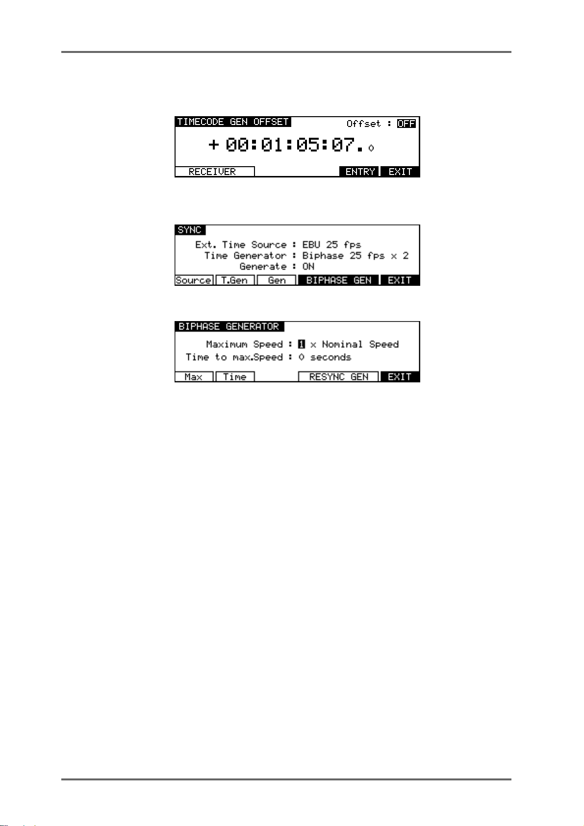
SYSTEM - 8
A similar of fset can be applied to the output of the timecode generator. Press the GENERATOR
softkey (F1/F2) on the TIMECODE RCV OFFSET page to goto the TIMECODE GEN OFFSET
page:
BIPHASE GENERATOR
If Time Generator is set to one of the Biphase options, an additional soft key appears :
Pressing BIPHASE GEN (F4/F5) accesses the Biphase generator settings page :
In this page, you can set certain parameters that affect the biphase generator. The parameters
are:
MAXIMUM SPEED Different pieces of bi-phase film equipment are capable of different
rewind and fast forward speeds. This parameter should be set to
allow for the connected machine’s maximum rewind/fast forward
speeds. The parameter can be set from 1-30 times normal play
speed. Please check your film equipment when setting this as incorrect setting may result in damage to the equipment or to the film
or tape. Pressing Max (F1) moves the cursor to this field.
TIME TO MAX SPEED This allows you to set how long it will take for the connected equip-
ment to reach its maximum rewind or fast forward speed. The range
is 0-10 seconds. Please check your film equipment and ensure
that a sensible value is set here as damage to your film equipment
could result. Pressing Time (F2) moves the cursor to this field.
When the DD8 is acting as a biphase master, pressing RESYNC GEN will reset the DD8’s
biphase generator to zero and from then on, the film player will count the biphase pulses and all
sync will be relative to that start point.
To leave the BIPHASE GENERATOR page, press EXIT. You will return to the SYNC page.
Going back to SYNC page, pressing Gen (F3) moves the cursor to the Generate field.
Here, you may choose the type of timecode generate mode. The available options are:
OFF - This options turns off the DD8’s timecode generation.
ON - This selects that the DD8 will generate the timecode at the selected frame
rate at all times.
Page 70 DD8
plus
Version 2.20 - September 1998
Page 81

SYSTEM - 8
via SYNC key - This selects that the DD8 will generate the timecode at the
selected frame rate when the SYNC key is ON.
ADVANCED TIMECODE OPTIONS
A new page has been added with options to control subtle features concerning the DD8’s response when chasing timecode.
The ADVANCED TIMECODE OPTIONS page is a new ‘hidden’ page accessed by pressing
ENTER + F1 on the SYSTEM SYNC page.
Filter EXITDelayChase
The REVERSE CHASE field allows playback audio to be muted while the transport is chasing
reverse timecode. This can be useful when the DD8 is being controlled from an older synchroniser
that does not support random access machines. Often, these devices spool to locate to a new
position which can result in annoying bursts of audio from random access machines
The options for the REVERSE CHASE field are:
UNMUTED The DD8 will attempt to play audio while chasing reverse timecode.
MUTED The DD8 will mute playback while chasing reverse timecode.
The MUTE DELA Y field determines the delay after locking to incoming timecode until the audio
outputs are unmuted. In multi-machine systems, this field can be set to allow an adequate delay
to allow the playback on all machines to start virtually simultaneously. Note that MUTE DELAY
only affects playback in the forward direction.
The DROP OUT FILTER field determines the approximate drop-out length (in frames) which will
cause the DD8 to stop playback or drop out of record. The recommended value is 15. A shorter
length is useful for forcing playback to stop more abruptly when the timecode source is stopped.
Note however that a short length may prevent the machine locking to very slow-moving timecode.
plus
Version 2.20 - September 1998
Page 71DD8
Page 82

SYSTEM - 8
DISPLAY
Pressing DISP (F3) on the first System Settings page takes you to the Display menu :
Pressing Style (F1) moves the cursor to the Style field.
This allows you to set the type of timecode you wish the DD8 to display. Normally, this is the
same as the timecode type selected in the EXT. TIME SOURCE field on the SYNC page (and
the DD8 will take care of this automatically) but you may choose to view another time display if
you wish. The selections are:
AS EXT. TIME SOURCE - The time display style is automatically selected to be the same as the
timecode selected in the EXT. TIME SOURCE field.
23.98 fps - 23.98 frames per second (24 frames per second with a 0.1% pulldown
for use when synchronising film to NTSC video).
24 fps - 24 frames per second.
25 fps - 25 frames per second.
29.97 fps - non-drop 29.97 frames per second.
29.97 fps drop - drop frame 29.97 frames per second.
30 fps - non-drop 30 frames per second.
30 fps drop - drop frame 30 frames per second.
Feet, 24fps 16mm - feet and frames at 24 frames per second as referenced to
16 mm film.
Feet, 24fps 35mm - feet and frames at 24 frames per second as referenced to
35mm film.
Frames, 24fps - frames only at 24 frames per second.
Frames, 25fps - frames only at 25 frames per second.
Frames, 30fps - frames only at 30 frames per second.
Frames, 29.97fps - frames only at 29.97 frames per second.
Hr:Min:Sec:mS - time will be displayed in hours, minutes, seconds and millisec-
onds.
Seconds (Secs.mS) - time will be displayed in seconds and milliseconds only.
25fps film (+4.1%) - display 25 frames per second but with a 4.1% playback
speed offset for use when working with material that has been transferred from
film to video.
24fps film (-4%) - display 25 frames per second but with a 4% playback speed
offset for use in European film applications when working with material that has
been transferred frame-by-frame from 24fps film to 25fps video.
Page 72 DD8
plus
Version 2.20 - September 1998
Page 83

SYSTEM - 8
NOTE 1: It must be said that some of the latter options are for use in very specialised applica-
tions. You will know if they are useful for you. The normal selection made is 24, 25, 29.97 or
30fps. Those working in film or cartoons may like to use other display styles.
Pressing Sub-F (F2) moves the cursor to the Sub-Frames field. This selects how many subframes will be displayed per frame. Available selections are :
OFF The sub-frame display is switched off
10th Frames Normal display with 10 sub-frames per frame
Film Perfs This counts film perforations at 4 perforations per frame.
Video Fields This counts video fields at 2 fields per frame.
Pressing Meters (F3) moves the cursor to the Meter Mode field. This controls the meter’s peak
hold function. Available selections are :
NORMAL Peak level is displayed momentarily
HOLD Peak level is displayed indefinitely on the meters
Pressing LCD (F4) moves the cursor to the LCD Contrast field. This allows the contrast of the
LCD display to be changed for better visibility by using the DATA +/- keys.
DISPLAY OFFSET
Pressing OFFSET (F5) takes you to the DISPLAY OFFSET page:
When the OFFSET field is OFF, the timecode displays will show either absolute or relative time
as selected. When the OFFSET field is ON, the timecode displays will show be adjusted according to the offset shown on this page.
To enter a new offset value press the ENTRY key (F5):
Soft keys F1 and F2 can be used to move the cursor to the sub-frame field, or any of the other
fields. The offset time is then entered using the track keys as a numeric keypad or the current
digit can be nudged using the DATA +/- keys.
The offset sign (plus or minus) can be toggled by pressing the +/- key (F4).
FOOTAGE DISPLAY
When footage (Feet/Frames) display styles are selected on the SYSTEM ‘DISPLAY’ page, the
current position is calculated using the MARK time as zero footage. Other timecode offsets are
ignored. This allows a project to be setup with a TIMECODE RCV OFFSET for use when the
project is loaded into a machine chasing LTC as well as a separate and unrelated footage zero.
plus
Version 2.20 - September 1998
Page 73DD8
Page 84

SYSTEM - 8
RECORD SETUP
Pressing RECORD (F4) on the first System Settings page takes you to the Record Setup
menu :
Pressing the XFade key (F2) moves the cursor to the CrossFade Time field. This allows a
record crossfade of 0 to 80ms to be set.
Pressing Monitr (F3) moves the cursor to the Record Monitor field.
Here you may select how you will monitor the input signal. The default selection is RECORD
AND STOP. With this selected, you will hear the input signal under the following conditions:
HEAR INPUT?
RECORDSTOP PLAYBACK
YES NOYES
RECORD TRACK'S PLAY SELECT KEY ON
RECORDSTOP PLAYBACK
HEAR INPUT?
RECORD TRACK'S PLAY SELECT KEY OFF
YESYES
YES
The other selection you may make is RECORD ONL Y. With this selected, you will only hear the
input signal whilst actually recording, regardless of the status of the record track’s PLAY select
key. I.e.:
RECORDSTOP PLAYBACK
HEAR INPUT?
RECORD TRACK'S PLAY SELECT KEY ON OR OFF
YESNO
NO
RECORD ONLY is useful when you only ever want to hear the input signal during record and at
no other time. The DD8 will take care of the switching automatically.
Page 74 DD8
plus
Version 2.20 - September 1998
Page 85

SYSTEM - 8
** IMPORTANT NOTES REGARDING TRACK MONITORING DURING RECORDING **
On analogue multi-track tape recorders, we take seamless punch-in/out for granted. However, this is much more difficult to achieve on hard disk recorders.
The DD8 has seamless punch-in/out and to achieve this, the DD8 plays previously recorded
material in the background so that, when you punch-out manually, the track is ready to play
back immediately with no gap at the punch-out. I.e.:
PUNCH-IN PUNCH-OUT
NEW RECORDING
PLAY PLAYMUTED
ORIGINAL RECORDING
This means that in most cases, the DD8 will drop in and out of record pretty much like a
normal MTR. Usually, on most hard disk recorders, due to disk speed restrictions and SCSI
bandwidth, there is a gap of several seconds or more at the point of drop-out. This is not so on
the DD8 and it is possible to punch in and out seamlessly on mono and stereo tracks.
However, when using an MO, because these are slower than hard disks, you may notice
tracks dropping. Also, when recording four tracks, there may be gap in monitoring when you
drop out of record. The actual recording will be fine - only the monitoring at the point of punchout will be momentarily affected.
As mentioned, though, under normal circumstances, when recording stereo or mono cues
onto either a hard disk or MO, you should not notice this.
Pressing Mode (F4) moves the cursor to the Record Mode field. The available selections are :
NORMAL This is the default mode where new recordings are made onto an unused
area of the disk. Note that recording in this mode is non-destructive (existing audio on the disk is not overwritten and it is possible to recover the
original audio using the UNDO function).
DESTRUCTIVE This is a special type of record mode that behaves more like traditional
tape.
As mentioned, recording on the DD8 is non-destructive by default but,
sometimes when recording, it is possible to build up a lot of redundant
audio on your disk, especially if you are dropping in and out over the
same point time and time again (for example, when recording dialogue).
As a result, your disk can soon become full of audio you cannot access or
use. The DESTRUCTIVE record mode goes some way to overcome this.
plus
Version 2.20 - September 1998
Page 75DD8
Page 86

SYSTEM - 8
When DESTRUCTIVE recording mode is on, if you record over an entire
cue, the audio associated with the original cue will be erased from disk.
However, you must record over the original cue completely - dropping in
and/or out half way through the cue will not cause the original cue’s to be
deleted from disk. For example:
DROP IN DROP OUT
Will not erase original recording
DROP IN DROP OUT
Will not erase original recording
DROP IN DROP OUT
Will not erase original recording
DROP IN DROP OUT
Will erase original recording
DROP IN DROP OUT
Will erase original recording
When recordings are made in DESTRUCTIVE mode, the ends of overwritten files are deleted to
recover disk blocks (similar to the process during disk MINIMISE).
Page 76 DD8
plus
Version 2.20 - September 1998
Page 87

First Recording:
Second Recording:
RECORDING 1
The area marked
from RECORDING 1 will be deleted to
recover disk space.
SYSTEM - 8
RECORDING 1
RECORDING 2
NOTE: There are certain considerations regarding destructive recording that you should be
aware of.
• THERE IS NO UNDO FOR RECORDINGS WHEN DESTRUCTIVE MODE IS USED.
• After you have just loaded a new project, as a safety factor, recording over cues in that
project will not delete their audio from disk and the original project cannot be damaged.
If, however, you record over cues recorded since the project was loaded, newly recorded
cues’ audio will be deleted from disk.
The destructive record mode will go some way to avoiding the build up of
unnecessary audio on your disk but, given the above points, there may
be times when you will need to perform a manual cleanup or minimise.
plus
Version 2.20 - September 1998
Page 77DD8
Page 88

SYSTEM - 8
SURE IT IS NOT INADVERTENTLY SELECTED WHEN RECORDING AS YOU RUN THE
For example, if you are used to using non-destructive recording but receive a disk where
DESTRUCTIVE record mode is enabled, you may be working in your usual way, thinking
that new recordings are recoverable when, in fact, they are being deleted from disk every
time you record over them. A good example may be where you are repeatedly dropping in
over dialogue recordings, unaware that DESTRUCTIVE mode is set. You may think that
Pressing Punch (F5) moves the cursor to the Punch Mode field. This selects how the DD8 will
respond if the record track selection is changed while the transport is in record.
Available selections are :
** WARNING **
BECAUSE OF THE DESTRUCTIVE NATURE OF THIS FUNCTION, PLEASE MAKE
RISK OF LOSING VALUABLE DATA.
you can retrieve ‘out-takes’ after the talent has left only to find that only the very latest
recordings you made are available on disk. In this case, before recording over existing
cues, please check that DESTRUCTIVE record mode has not been selected.
** THERE IS NO UNDO WHEN DESTRUCTIVE RECORD IS USED **
NORMAL This is the default setting. The record track selection can not be changed
while the transport is in record.
TRACK KEYS In this mode, the transport responds in the same manner as a conven-
tional MTR. Pressing the REC and PLAY keys will put the DD8 into a
‘record-ready’ condition waiting for tracks to be punched in from the track
select keys. If no tracks are selected at the time the REC and PLA Y keys
are pressed, the REC key will flash. In this situation, when any of the
track select keys are pressed the DD8 will punch into record on the selected track(s) and the REC key will light steadily. When the track select
key is pressed again, that track will be punched out of record.
PRIMED In this mode, recording will start immediately on selected tracks when the
REC and PLA Y keys are first pressed. After this, if new record tracks are
selected, the appropriate track select key(s) will flash indicating that the
track is in ‘record-ready’, but recording will not actually start until the PLA Y
key is pressed again while holding down the REC key. While in record,
pressing the track select key of a track that is actually recording will punch
that track out of record and back into the ‘record-ready’ state.
Page 78 DD8
plus
Version 2.20 - September 1998
Page 89

SYSTEM - 8
ROUTING INPUTS
Pressing INPUTS (F1) accesses the Input Routing page :
This shows the default assignment for a system with eight analogue inputs with each input being
routed to the 8 tracks.
Pressing Type (F1) moves the cursor to the Input Type field which allows you to select between
ANALOG or DIGITAL inputs (depending on the option boards fitted).
Pressing MONO (F3) recalls the MONO preset (Input 1 to all tracks)
Pressing STEREO (F4) recalls the STEREO preset (Inputs 1&2 to all pairs of tracks)
Pressing RESET (F5) recalls the default assignment (Inputs 1-8 to tracks 1-8)
Other Input assignments are made by pressing the Track Key (1-8) to select a track and then
using the DATA +/- keys to select the required input.
SPEED
Pressing SPEED (F5) on the first System Settings page takes you to two pages depending on
the SYNC status of the DD8.
If the SYNC key is switched OFF (Internal Time Source), pressing SPEED (F5) takes you to
the VariSpeed menu :
F1/F2 (</>) moves the cursor from one digit to another in the SPEED field and F3 (Vari ?)
toggles VariSpeed ON/OFF.
If SYNC is ON (Chasing External Time Source), the SPEED key takes you to the External Source
Speed page:
In this page, there are no user parameters. This is used only as a Time Source analyser , in order
to check the Source format and quality (speed and stability).
plus
Version 2.20 - September 1998
Page 79DD8
Page 90

SYSTEM - 8
SECOND SYSTEM SETTING PAGE
Pressing MORE (F6) on the first SYSTEM SETTINGS page will show this screen:
The functions are:
OPERATING LEVEL
Pressing LEVEL (F1) on the second System Settings page takes you to the Operating Level
page:
Reference Level (F1) The Reference Level : is used to set the 0 VU of the A/D and D/A converters.
Available selections are -12 dB , -16 dB, -18 dB and -20 dB.
Meter Ref Flash (F2) This function may to used to allow accurate calibration of operating lev-
els to and from the DD8. When the METER REF FLASH mode is switched on, the REF light on
the barmeters will flash when the input signal is within approximately 0.4dB of the current operating level setting.
PRE-READ
Pressing P-READ (F3) on the second System Settings page takes you to the Pre-Read menu :
PRead (F1) Moves the cursor to the Pre-Read On/OFF field. This enables the Pre-
Read function and causes the DD8 to load pre-read data into memory.
NOTE: The Pre-Read function requires an area of memory to store information about the
audio files on disk. The DD8 also requires memory for storing large items such as disk directories. In some circumstances, you may receive an “OUT OF MEMORY” error message
when trying to enable the Pre-Read function. This indicates that the DD8 is unable to allocate
sufficient memory to allow this function to be used. This can be overcome by installing CPU
expansion RAM in the DD8.
Pre-Delay (F2/F3) Moves the cursor to the Pre-Delay field (F2 (<) for the units, F3 (>) for the
decimal). This is the time before the current NOW time at which the track’s
Pre-Read output will be activated.
Threshold (F4/F5) Moves the cursor to the Threshold field. This sets the detection threshold
of the selected track. Select the required track using the Track Keys (1-8)
or the ALL key (to set all the same threshold on all tracks).
Page 80 DD8
plus
Version 2.20 - September 1998
Page 91

SYSTEM - 8
TIMES
Pressing TIMES (F4) on the second System Settings page takes you to the Times menu :
To (F1) Moves the cursor to the Play To field. This sets the amount of audio (be-
fore the NOW time) that will be played when the TO key is pressed.
From (F2) Moves the cursor to the Play From field. This sets the amount of audio
(after the NOW time) that will be played when the FROM key is pressed.
JOG
Pressing JOG (F5) on the second System Settings page takes you to the Jog menu :
Pressing Jg Res (F1) move the cursor to the JOG Resolution field.
Available values are :
NORMAL Normal Jog wheel response
FINE Fine jog wheel response
Pressing Jg Max (F2) moves the cursor to the Maximum JOG Speed field. This may be set to
a maximum of 5 x play speed.
Pressing Sp Max (F3) moves the cursor to the Maximum Spool Speed field. This may be set
to a maximum of 5 x play speed.
plus
Version 2.20 - September 1998
Page 81DD8
Page 92

SYSTEM - 8
REMOTE
Pressing REMOTE (F2) on the second System Settings page takes you to the Remote menu :
Soft keys are only shown for the installed option boards. If certain boards are not installed,
they will not be detected by the DD8 and their keys will not be shown here.
Pressing the AKNET key takes you to a page which shows the Ethernet ID number assigned to
the machine. This number is programmed during production.
The other parameters on this page are described later in the section on MULTI-MACHINE OPERATION.
The pages available from the GPIO and RS422 keys are described later in the sections on GPIO
and RS422.
Pressing the MIDI key takes you to the following page:
This allows you to setup the DD8 as a SLAVE for MIDI MACHINE CONTROL when the MIDI
option board is installed.
Page 82 DD8
plus
Version 2.20 - September 1998
Page 93
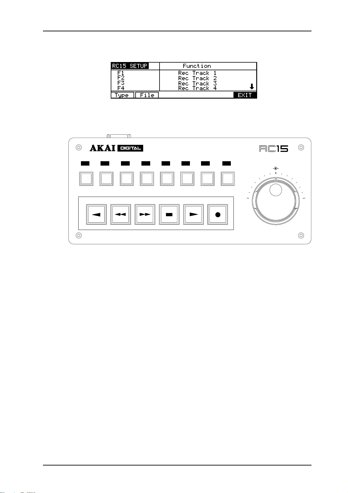
SYSTEM - 8
If an RC15 Remote Controller is attached to the DD8, a soft key labelled “RC15” will be shown
on the REMOTE page. Pressing the RC15 key takes you to the following page:
The RC15 is a small optional remote controller that connects to the EXPANSION connector on
the rear-panel of the DD8. As well as a jog/shuttle wheel, it has 8 function keys (F1..F8) and 6
transport keys, each of which can be assigned to a variety of functions:
USER ASSIGNABLE
REMOTE CONTROLLER
F1 F2 F3 F4 F5 F6 F7 F8
JOG
SHUTTLE
The RC15 keys are listed in the column on the left hand side of the RC15 SETUP screen. The 8
transport keys are listed as F1..F8, and the transport keys are listed as TRANSPORT 1 .. TRANSPORT6.
The DATA+/- keys are used to select the function for each key and the PREV/NEXT keys (F1/
F2) are used to scroll up and down through the list of RC15 keys.
The options available are:
REWIND Rewind transport
FAST FORWARD Fast Forward transport
STOP Stop transport
PLAY Put transport into play
RECORD Send record command when PLAY is also pressed
REC (PUNCH-IN) Drop into record
REC (TOGGLE) Drop in/out of record
PLAY REVERSE Play backwards
STORE IN Grab IN time
STORE OUT Grab OUT time
plus
Version 2.20 - September 1998
Page 83DD8
Page 94

SYSTEM - 8
STORE MARK Grab MARK time
SYNC (ON-LINE) Switch EXT.TIME on/off
REHEARSE Switch REHEARSE on/off
AUTO-PUNCH Switch AUT O-PUNCH on/off
REC TRACK 1-8 Switch selected record track on/off
BPH RCV RESYNC Resync biphase receiver
BPH GEN RESYNC Resync biphase generator
Page 84 DD8
plus
Version 2.20 - September 1998
Page 95

SYSTEM - 8
THIRD SYSTEM SETTING PAGE
Pressing MORE (F6) on the second SYSTEM SETTINGS page will show this screen:
The functions are:
TRACK MAPPING
Pressing TRACKS (F1) on the third System Settings page takes you to the T rack Mapping page:
This page is used to assign ‘virtual’ tracks from the current project to the 8 playback tracks. For
example, if you are using a project created on the DD1500 or DR16 with 16 tracks, you can
choose which 8 of these tracks you want to play on the DD8. The soft keys ‘1-8’ (F1) and ‘9-16’
(F2) can be used to quickly select tracks 1-8 or 9-16 for playback. You can also select individual
tracks by using the track keys (1-8) to select a playback track and using the DATA +/- keys to
select the required source. After changing the mapping for individual tracks a new soft key, SET
MAPPING, will appear. Press this key (F4/F5) to confirm your selection.
SAVE SETTINGS
Pressing SA VE (F2) on the third System Settings page takes you to a page which allows you to
save the current system parameter settings:
If you want to save the settings to disk with the current project, select WITH PROJECT (F3/F4).
If you want to save the settings to flash ROM (where they will become the default settings for
new projects created), select FLASH ROM (F1/F2).
LOAD SETTINGS
Pressing LOAD (F3) on the third System Settings page takes you to a page which allows you to
load the current system parameter settings:
Pressing LOAD (F1/F2) will replace the current system settings with those stored in Flash-ROM.
plus
Version 2.20 - September 1998
Page 85DD8
Page 96

SYSTEM - 8
CLEAR SETTINGS
Pressing CLEAR (F4) on the third System Settings page takes you to a page which allows you
to clear the current system parameter settings from the Flash ROM:
Pressing CLEAR FLASH (F1/F2) will clear the Flash ROM parameter settings.
REAL-TIME CLOCK
Pressing CLOCK (F5) on the third System Settings page takes you to the SYSTEM CLOCK
SETUP page:
To change the current time, press HOURS (F1), MINS (F2) or SECS (F3) to move the cursor to
the required field and use the DA TA+/- keys to adjust the time. Pressing SET DATE (F4/F5) will
change the soft-key selections to allow you to move the cursor to the date fields:
The Real-time clock is used to timestamp new files and recordings as they are saved to disk.
Page 86 DD8
plus
Version 2.20 - September 1998
Page 97

MULTI-MACHINE OPERATION
It is possible to connect up to 16 DD8s for control from a single DL1500.
TERMINATOR OFF
TERMINATOR OFF
TERMINATOR ON
SYSTEM - 8
The units are chained together by the AKNET BNC connector on each machine using standard
Ethernet BNC cables and ‘T’ pieces. It is essential that the TERMINATOR switch is switched to
the ON position on first and last units in the chain. Failure to do so will prevent correct communications and the system will not work..ii.AKAINET Termination;
NOTE: The AKNET interface used in the DD system is 10-Base-2 Ethernet. There are cer tain rules that must be adhered to when setting up the system to ensure reliable operation:
• All cables should be 50 ohm impedance.
• There should be a maximum of 185m of cable in the system between the first and last
nodes.
• There should be at least 0.5m of cable between each node.
Before the system is used for the first time, each DD8 must be assigned a unique machine
number which is used to identify it. This is set on the AKNET INFO page which is accessed from
REMOTE page in the SYSTEM menus:
NOTE: The MACHINE NAME field can not be edited from the DD8 front panel. This can be
changed from the DL1500.
plus
Version 2.20 - September 1998
Page 87DD8
Page 98

SYSTEM - 8
DD8 AS AN RS422 MASTER
The DD8 can be used as an RS422 master using the Sony™ P2 protocol. This means that all
play, jog, shuttle and locate commands are issued from the DD8 allowing you to control a VTR
equipped with RS422 and the DD8 together. Connections should be made as shown below with
the DD8’s RS422 option board output connected to the VTR and the timecode output from the
VTR connected to the DD8’s LTC option board timecode input.
VIDEO
MONITOR
House Sync Source
Audio inputs
Audio outputs
T/C out
RS422 equipped VTR
To DD8 SMPTE input
RS422
DD8 (with RS422 and LTC option boards)
RS422 SETUP PAGE
Pressing the SYSTEM key followed by REMOTE and RS422 takes you to the RS422 SETUP
page where you can setup functions to cater for the VTR’s transport mechanism.
If RS422 MASTER is selected in the RS422 MODE field. You will see this screen:
The parameters are:
VTR PRE-ROLL Most VTRs require a certain amount of ‘run up’ time when sync’ed to
external equipment. This field sets that time. When a value is set here,
locating to any position will automatically cause the system to locate to a
point slightly earlier than actually specified. In the above example, if you
locate to 1 minute, the DD8 will actually locate to 55 seconds.
Page 88 DD8
plus
Version 2.20 - September 1998
Page 99

SYSTEM - 8
NOTE: YOU MUST SELECT ONE OF THE SMPTE/EBU+RS422 OPTIONS AT A FRAME
RATE APPLICABLE TO YOUR AREA WHEN USING RS422 MASTER.
These options are available at all frame rates. SMPTE/EBU from the VTR is still connected as
usual to the LTC option board’s input and the SYNC key must be switched on. The DD8 will
receive timecode information in playback from the L TC connection but, when working in slow
motion, it receives timecode over RS422 making locking of the two machines tighter.
Switching on the SYNC key engages the RS422 function. Because of the frame accuracy limit
imposed on the DD8 by the VTR over RS422, it is sometimes necessary to ‘isolate’ the DD8 for
greater editing accuracy. T o do this, simply switch of f the SYNC key - this will allow the DD8 to be
used ‘stand alone’.
As a practical example, let’s say you are trying to sync a door slam sound effect in the DD’s
project with the picture on video. You could, of course, do everything referenced to frame accurate picture but, you just cannot get the door slam precisely in sync. By switching off the SYNC
key , you can momentarily disengage the VTR, ‘isolating’ the DD8 and you can place the sound
effect, nudging it backwards or forwards in sub-frame increments on the DD8 until you think it’s
at the right position. You can then re-engage the VTR by switching on the SYNC key again and
trying it out against picture. You can repeat this process until it’s perfectly in sync.
LAYBACK FUNCTION IN RS422 MASTER
LAYBACK is a process where you have material on the DD8 that you wish to ‘master’ onto a
VTR or other such RS422 equipped machine (such as an RS422 DAT machine). For example,
you may receive a video tape with just dialogue on it. This is sync-transferred to the DD8 where
it may be edited and tidied up if necessary and sound effects, music and other ‘sweeteners’ can
be added using the DD8’s multi-track capabilities. Finally, the whole thing is transferred back to
the VTR.
To use the LAYBACK function, press LAYBACK (F4/F5). You will see this screen:
The parameters are:
LA YBACK T O TRACKS Here you may select which of the VTR’s tracks the material will be
recorded to. Y ou may select VTR tracks 1, 2, 3, 4, 5, 6, 7, 8 (mono)
or 1+2, 3+4, 5+6, 7+8 (stereo) or 1-4, 5-8 or 1-8.
TRACKS ENABLED Here you may select whether the layback (i.e. the mixdown) will be
to the VTR’s analogue tracks or its digital tracks. You may also
select ANALOG+DIGITAL which will cause the layback to be recorded to both the analogue and the digital audio tracks of the
VTR.
plus
Version 2.20 - September 1998
Page 89DD8
Page 100

SYSTEM - 8
The soft key functions are:
PVIEW This allows you to ‘rehearse’ (preview) the layback (i.e. it will go
LA YBACK Pressing this will initiate the layback process (i.e. the VTR will play
NOTE: If tracks are accidentally enabled for record on the DD8 they will be ignored when
using the LAYBACK function.
USING THE LAYBACK FUNCTION
The DD8’s IN and OUT markers set the record in/out points for the VTR. Assuming the functions
described above are set as appropriate, press LA YBACK and the VTR will drop in/out of record
at the IN/OUT points marked.
Y ou may ‘build’ the final transfer in sections (in this way, you can obtain the optimum mix sectionby-section) and set IN/OUT points as appropriate. You may rehearse the drop in/out using PREVIEW and, when you’re happy with the results, press LA YBACK to actually ‘commit’ the recording.
into E-E mode at the IN point and will then stop at the OUT point).
This function allows you to check whether the edit will be successful or not.
to the IN point and will drop into record on the VTR. When the OUT
point is reached, it will stop).
It may be that you want to transfer the whole project back to the video tape in one go. In this
case, set the IN at the start of the project and the OUT at the end of the project and press
LAYBACK (F3/F4) to transfer the whole project back to the master video tape in one pass.
Another use of this may be to receive a video tape as described above but the ‘sweetened’
version on the DD8 may be laid back to an RS422 equipped DAT machine thus preserving the
dialogue on the original video with a synchronised ‘master’ on DAT.
RS422 MASTER CONTROL OF NON-LINEAR VIDEO RECORDERS
Using the ‘RS422 only’ external timecode selection, it is possible to take full advantage of nonlinear hard disk video recorders such as the AKAI DV1500 or FED V-MOD 100.
When using any of the SMPTE+RS422 external timecode options, although locate/lock times in
this case are virtually immediate, when jogging at slow speeds, there is no significant performance improvement over a VTR and the non-linear video recorder will ‘stutter’ frame by frame
much like a normal VTR. However, using the ‘RS422 only’ selection, slow speed jogging is
exceptionally smooth and very tightly locked to the DD8’s audio jogging and so is ideal for
spotting audio to picture.
However, please note that because of inaccuracies in the timecode sent via RS422, when playing at nominal speed, there may be instances where there is a ±1 frame offset. This can be
overcome by switching to SMPTE+RS422 for playback and using RS422 only for jogging and
spotting. Of course, in the RS422 SETUP page, RS422 MODE must be set to MASTER and the
SYNC key must be switched to ON.
Page 90 DD8
plus
Version 2.20 - September 1998
 Loading...