Akai AMU-4 Schematic

V I I . A M P L I F I E R A D J U S T M E N T
AKAI AMU-04
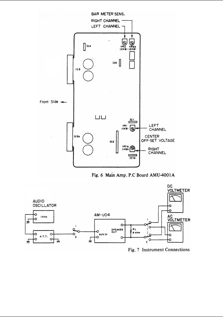
1. CENTER OFF-SET VOLTAGE
ADJUSTMENT (Refer to Figs. 5, 6)
Connect the Digital Voltmeter or DC Voltmeter to the Speaker terminal. Adjust the VR1 (1 kB) on the Main Amp P.C Board, so that the Voltmeter reading is 0 ±10mV.
2. BAR METER SENSITIVITY ADJUSTMENT (Refer to Figs. 5, 6)
The Meter Switch should be set to “x1”.
Connect a load resistor (RL: 8 ohms) to the Speaker terminal, and input 1 kHz through the AUX terminal. Adjust the VR2 (2 kB) on the Main Amp P.C Board until the voltage at both ends of the load resistor is 10.95 V (AC voltmeter) where the Power Meter indicate 15 watts.
10

V I I I . C L A S S I F I C A T I O N O F V A R I O U S P . C B O A R D S
AKAI AMU-04
1. P.C BOARD TITLES AND IDENTIFICATION NUMBERS
P.C Board title |
P.C Board Number |
|
|
|
|
Main Amp P.C Board |
AMU-4001 A |
|
|
Push Switch P.C Board |
AMU-4001 B |
|
|
LED P.C Board (B) |
AMU-4001C |
|
|
Selector P.C Board |
AMU-4002 |
|
|
Tone Control P.C Board |
AMU-4003 |
|
|
Pin Jack P.C Board |
AMU-4005 |
|
|
Fuse P.C Board (U/T) |
AMU-4006 |
|
|
Fuse P.C Board (CSA, AAL) |
AMU-4058 |
|
|
Fuse P.C Board (JPN) |
AMU-4060 |
|
|
Fuse P.C Board (CEE, UK, SAA) |
AMU-4059 |
|
|
LED P.C Board (A) |
AMU-4007 |
|
|
Slide Volume P.C Board |
AMU-4008 |
|
|
Loudness P.C Board |
AMU-2003 |
|
|
Bar Meter P.C Board |
AMU-2006 |
|
|
Chart-1
11
 Loading...