

Page 1
AKAI CT 2867 UNT
1
General Information
Also Covers
CT 2567 UNT
CT 2865 UNT
CT 2161 UNT
CT 2565 UNT
Specifications
Mains power ........................................................................................................... 176-264 V
Power consumption ................................................................................................ ca. 90 W
Stand by .........................................................................................................................0,1 W
...................................................................................................................... 28”/71 cm (110°)
Programme memory loc. ................................................................................................... 99
AV memory locations........................................................................................................... 2
AV memory locations
(CT-25/2867 UNT, CT-2867 UNT DPL) ................................................................................. 3
Sound output ........................................................................................ 2 x 6,5 W RMS (8 Ω)
Dolby Surround:
Surround channel
Centre channel
Chassis:
mains isolated
Connections: on the front panel
...................................................................................................................... ≥16 Ω 3,5 mm
................................................................................................................ AV (Cinch/Hosiden)
Connections: on the rear panel
Audio out: 0,5 V/1 kΩ
Scart 1/ Scart 2 ................................................................................... Audio in: 0,5 V/10 kΩ
.................................................................................................................Video out: 1 V/75 Ω
................................................................................................................... Video in: 1 V/75 Ω
................................................................................................................ SVHS: Y/C (Scart 1)
...................................................................................................... RGB: 0,7 V/75 Ω (Scart 1)
OSCAR 5 Commander
Aerial................................................................................................................................ 75 Ω
Service Adjustments
Note! Before other adjustments U1 voltage must be adjusted.
Display Note
V.MID-POS. ............................. Adjust centre of the test picture vertical to
................................................. a centred pos. (bottom half is black).
V.TOP-POS. ............................ Adjust top edge (bottom half is black).
V.AMPL. .................................. Adjust bottom edge.
H.SHIFT................................... Adjust centre of the test picture horizontal
................................................. to a centred position.
H.AMPL. .................................. Horizontal amplitude
P.AMPL.................................... Horizontal cushion
P.TILT ....................................... Horizontal trapeze
R.CORN................................... Corner correction (starting SPL21 R 02)
S.COR. .................................... Vertical linearität (starting SPL21 R 02)
GREEN .................................... See adj. “G2- and colour temperature”
BLUE ....................................... See adj. “G2- and colour temperature”
RED ......................................... See adj. “G2- and colour temperature”
ACl........................................... (ON/OFF)SPL70
EQUALIZER ............................ (ON/OFF)SPL70
OSD SHIFT
IN VAR:.................................... (ON/OFF) starting SPL50 R 01
FRONT AV :.............................. (ON/OFF)
LOUDNESS: ........................... (ON)
C4 BIT CHECK: ...................... (ON)
NICAM:.................................... (ON/OFF)
CARRIER-MUTE:.................... (OFF)
VT CHAR: ............................... West / East1 / West Turkey / East2
FLYB MODE:........................... (ON=NTSC) as from SPL21 R02
AGC ......................................... See adjustment “AGC”.
ZOOM ...................................... (ON/OFF)
CORING .................................. (ON/OFF)
Warning!
Service and repair work to be performed only in
accordance with existing safety regulations.
X-ray regulations
The picture tube type and the maximum
permissible high-voltage ensure that the X-ray
intensity within the set remains far below the
permissible value.
The high-voltage must not exceed 28 kV. The
high voltage is within the permissible limits when
the operating voltage of the horizontal deflection
stage equals 150 V ± 0.5 V (110° 25”/28”),
130 V± 0.5V (90° 21”) or 120 V± 0.5V (90° 17”)
at minimum beam current. During servicing,
check and adjust this U1 voltage to the nominal
value. By following the service adjustments,
check and adjust this voltage to the nominal
value with R080.
Service mode
Select the service mode by pressing the Mute,
OK and TV buttons on the remote control unit.
Use the cursor button ▲ or ▼ to select required
adjustment and adjust it by using the cursor
buttons and .
Store into memory by pressing the red OK
button.
Return to normal TV mode by pressing the TV
button.
G2 - and colour temperature
1. Set the TV set to the service mode (see
“Service mode”).
2. Adjust the green, blue and red OSD values to
60 with the cursor button or
3. Set the G2 trimmer (RK60) to its centre
position.
4. Adjust the brightness to normal level (black
bar of the grey scale is black).
5. By using an oscilloscope (Probe 100:1)
determine the highest black value at the
picture-tube cathodes (R, G, B).
6. Adjust with G2 (RK60) the highest black value
to 150 V.
▲
▲
▲
▲
7. Use a colour neutral picture and adjust the
light areas in green, blue and red drives to
white (lower the OSD valuel with the cursor
button or . At least one of the level
controls should be remain at 60.
8. Store by pressing the OK button.
9. Return to normal TV mode by pressing the TV
button.
AGC
1. Feed in a RF signal (70 dBµV) tuned on a mid
range UHF channel and without sound carrier
via the aerial input.
2. Set the TV set to the service mode (see
“Service mode”).
3. Select the AGC-adjustment with the cursor
button ▲ or ▼.
4. Connect an oscilloscope (bandwidth > 50
MHz) to the IF output on the tuner (TL01 or
TL02).
5. Press the yellow button on the remote control
unit (OSD = OKAY).
6. Adjust the signal to 450 mVpp ± 50 mV. (with
reference to the signals synchronizing peaks)
with the cursor button or .
7. Store the value in the memory by pressing the
red OK button.
8. Return to normal TV mode by pressing the TV
button.
U1 voltage
1. Set the contrast and brigthness to minimum.
2. Connect an universal voltmeter to the
capacitor C043.
3. Adjust the U1 voltage to 150 V ± 0.5 V (110°
25”/28”), 130 V ± 0.5V (90° 21”) or 120 V ±
0.5V (90° 17”) with the trimmer R080 by black
picture.
Focus
Adjust the focus to optimum with the focus
trimmer (RK60).
Other service adjustments
Picture reference calibration
▲
▲
1. Press the blue MENU button twice.
2. Activate TV-PROGR option by pressing the
cursor button ▲ or ▼ .
3. Enter one of the mid range UHF channels by
using the number buttons, e.g. ch. 38 (607.25
MHz).
4. Select the frequency tuning menu by pressing
the green button.
5. Select AFC option and change it to ON by
using the cursor buttons or .
6. Adjust the frequency to 607.25 MHz with
▲
▲
ZL22 (even with other channels, always set to
xxx.25 MHz).
7. Return to normal TV mode by pressing the TV
button.
Audio IF calibration
1. Feed in a test picture.
2. Connect an oscilloscope to pin 12 of TDA
2545.
3. Adjust for minimum picture content with the
ZL02.
Recommended Safety Parts
Item Part No. Description
RK 55 3151 4519 SRES 1 K 0,25WW
RK 56 3151 4511 SRES 2,2E 0,25W
RK 60 3722 2010 FOCUS G2 REGULATOR
RK 72 3151 4516 ES 100E 0,25W
RK 73 3151 4513 RES 10 E 0,25W
RO 30 3156 0970 RES 8,2M 0,54W
CK 51 3345 0024 SCAP 8,7NF1600V
CK 52 3345 0026 SCAP 1,8 NF1600V
CK 61 3324 0835 SCAP 27NF 400V
CO 01 3345 0004 CAP 0,33MF 275V
CO 07 3324 0822 CAP 0,1 MF 250V
CO 30 3261 0932 SCAP 2,2 NF 4KV
CO 32 3261 0931 SCAP 1 NF 4KV
NE 50 3684 1033 PHOTO COUPLE
FO 01 4375 1251 FUSE 2,5A T
FO 02 4157 0485 FUSE HOLDER
TK 60 8681 7340 ANODENCLIP 4MM
TK 60 (4870,74,76) 4536 0032 DST ELDOR 1192.6002 NO 1/97
TK 60 (4800) 4536 0031 OST ELDOR 1192.6003
TK 60 (4876) 4536 0018 LINE TRANSFORMER
TO 30, 40 4523 1110 TRANSFORMER
NE 50 3684 1033 OPTOTCDT 1020G
SE 01 4121 0002 MAINSWITCH SAVE PUSH
SE 01 4193 0009 CONN CRIPLET
XH 01 4155 4034 CRT SOCKET METALLO
(CT2565/2865)
4) 28” 4362 9071 TUBE VID A66EAS13X01
4) 25” 4364 2511 TUBE VIDAS9EAS13X01
8) 25” 4588 0813 DEGAUSSING COIL
8) 28” 4588 0814 DEGAUSSING COIL
▲
▲
15) 4131 4380 MAINS CORD 2,25M UK
4774 0006 HIGH VOLTAGE CABLE
(CT2567/2867)
14) 25” 4364 2503 PICTURE TUBE A59CCY13X01
14) 28” 4364 2803 PICTURE TUBE A66ECY13X01
18) 25” 4588 0813 DEGAUSSING COIL
18) 28” 4588 0814 DEGAUSSING COIL
4131 4380 MAINS CABLE 2,25M UK
4774 0006 HIGH VOLTAGE CABLE
(CT2161)
15) 21” 4364 2104 TUBE90 Vid A51EFS83X191
19) 21” 4588 0811 DEGAUSSING COIL
4774 0006 HIGH VOLTAGE CABLE 620MM
7000 3707 UK POWER CORD + CONNECTOR 2,25m
Specifications / Adjustments / Variable Components for Picture Tube / Dolby Module / SP BG/DK/I Chassis / SP BG/DK/I Chassis Cont’d
SP BG/DK/I Chassis Waveforms / SP Multinorm Chassis / SP Multinorm Chassis Cont’d / SP Multinorm Chassis Waveforms / Safety Parts List
Page 2
2AKAI CT 2867 UNT
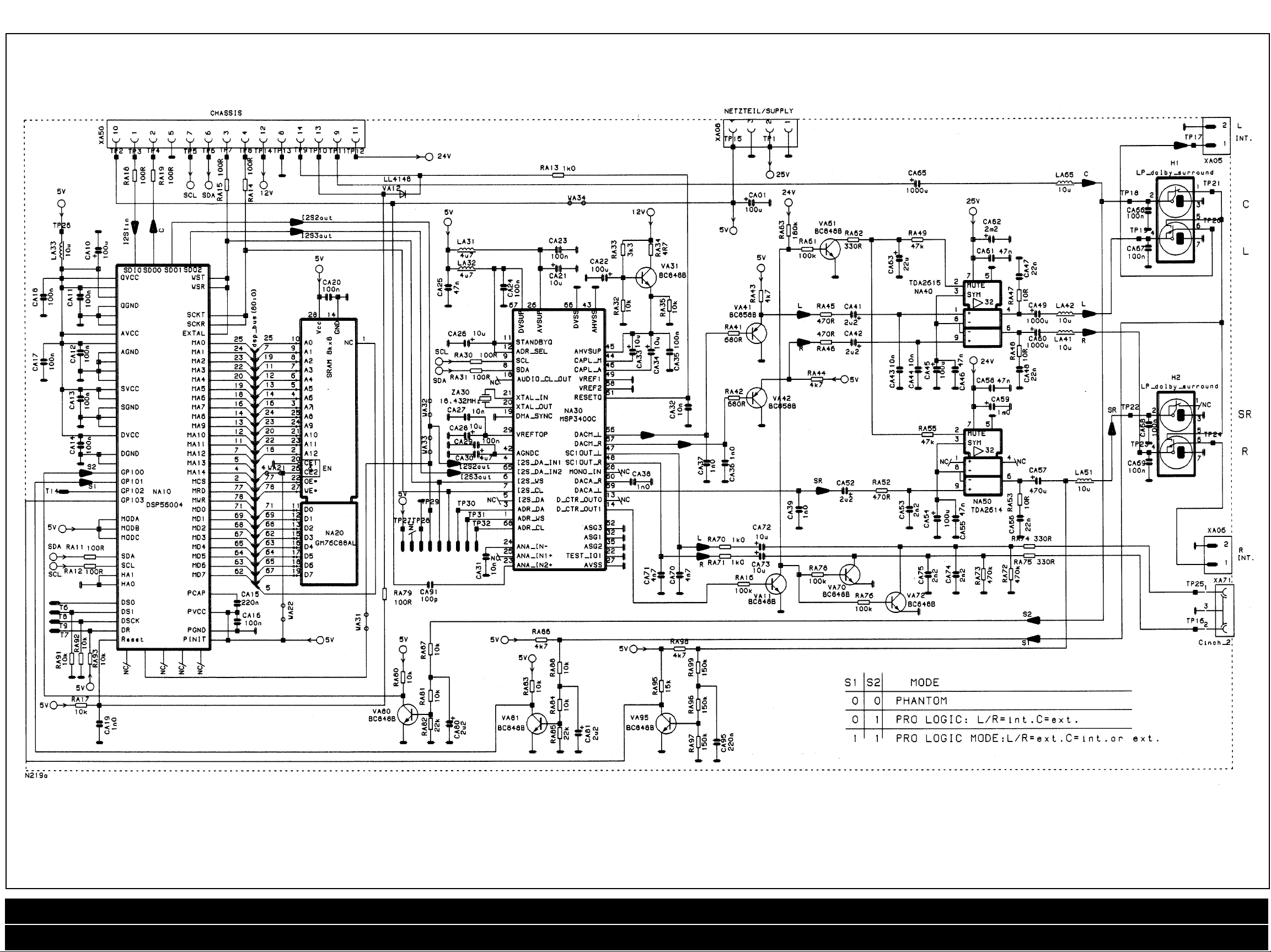
Dolby Module Diagram
Specifications / Adjustments / Variable Components for Picture Tube / Dolby Module / SP BG/DK/I Chassis / SP BG/DK/I Chassis Cont’d
SP BG/DK/I Chassis Waveforms / SP Multinorm Chassis / SP Multinorm Chassis Cont’d / SP Multinorm Chassis Waveforms / Safety Parts List
Page 3

AKAI CT 2867 UNT
Variable Components for Picture Tube
*POS A59/66 A59/66 A59/66 A59/66 A51 A51 A51 A41 A48
EAF10X01 ECY13X01 EAS13X01 ECF20X12 ECQ10X01 EFS43X191 EBV13X01 EAM40X01 EEV13X01
U1 150V 150V 150V 150V 130V 130V 130V 120V 120V
CO09 220U 220U 220U 220U 150U 150U 150U 150U 150U
CS26 33N 15N 33N 33N 1SN 15N 15N 15N 15N
CK51 8N7 8N2 8N7 8N7 6N8 6N2 5N6 4N7 6N2
CK52 1N5 1N5 1N5 1N5 1N5 1N5 1N5 2N2 2N2
CK53 120N 120N 120N 120N 120N 47N 120N 120N 120N
CK55 400N 300N 400N 360N 360N 360N 360N 360N 220N+270N
CKS6 33N 33N 33N 33N - - - 33N 33N
CK61 27N 27N 27N 27N 47N 47N 27N 18N 18N
CK65 4N7 4N7 4N7 4N7 4N7 4N7 4N7 15N 15N
LK5S 227U 227U 227U 227U 227U 227U 227U 227U 227U
LK61 490UH 480UH 490UH 490UH 360UH 360UH 490UH 610UH 610UH
LK65 82U 82U 82U 82U 75U 75U 75U 25U 25U
RK02 383 182 3R3 3R3 2R7 1R2 182 182 R39
RK06 10K 10K 10K 10K 330K 330K 330K 330K 330K
RK50 1R0 1R0 1R0 1R0 1R0 1R0 1R5 1R5 185
RK58 16K 16K 16K 16K 16K 16K 16K 20K 16K
RK63 66K 56K 56K 56K - - - - RK65 39R 39R 39R 39R 22R 22R 22R 62R 628
RK70 1R0 1R0 1R0 1R0 1R0 1R0 0R0 0R0 ORG
RK80 150K 470K 150K 150K 150K 150K 150K 150K 150K
RK85 3M3 2M2 3M3 2M2 3M3 3M3 3M3 3M3 3M3
RK88 100K 100K 220K 100K 100K 100K 100K 220K 100K
RO19 2K7 2K7 2K7 2K7 3K6 3K6 3K6 3K9 3K9
RO21 0K36 0K36 0K36 0K36 0K43 0K43 0K43 0K47 0K47
RO42 15K 15K 15K 15K 15K 15K 15K 12K 12K
RO43 2K2 2K2 2K2 2K2 100K 100K 100K 820K 820K
RO44 - - - - 15K 15K 15K 12K 12K
RO75 18K 18K 18K 18K 3K3 3K3 3K3 - Hotel 27K 27K 27K 12K 12K 12K 2K2 2K2
R078 51K 51K 51K 51K 51K 51K 51K 51K 51K
Hotel 59K 59K 59K 59K 59K 59K 59K 59K
RS11 300R 220R 300R 220R 220R 220R 220R 220R 220R
RS12 300R 220R 270R 220R 220R 220R 220R 220R 220R
RS13 380 4R7 380 2R0 2R0 383 bR - 8514 380 4R7 380 2R0 - - RS20 68K 68K 100K 68K 68K 68K 68K 68K 68K
RS25 560K - 560K 560K 560K 560K 560K 560K 560K
8526 150K 330K 150K 82K 100K 100K 100K 100K 100K
RS28 10K 100K 10K 10K 10K 100K 100K 100K 100K
TK60 M1015 M1015 M1015 M1015 M1009 M1009 M1009 M1016 M1016
C.R.T. board
RH20 2k2 2k2 2k2 2k2 2k2 2k2 2k2 3k0 2k2
RH30 2k2 2k2 2k2 2k2 2k2 2k2 2k2 3k0 2k2
RH40 2k2 2k2 2k2 2k2 2k2 2k2 2k2 3k0 2k2
3
SP BG/DK/I Chassis Diagram
Waveforms
Specifications / Adjustments / Variable Components for Picture Tube / Dolby Module / SP BG/DK/I Chassis / SP BG/DK/I Chassis Cont’d
SP BG/DK/I Chassis Waveforms / SP Multinorm Chassis / SP Multinorm Chassis Cont’d / SP Multinorm Chassis Waveforms / Safety Parts List
Page 4

4AKAI CT 2867 UNT
SP BG/DK/I Chassis
Diagram Cont’d
Specifications / Adjustments / Variable Components for Picture Tube / Dolby Module / SP BG/DK/I Chassis / SP BG/DK/I Chassis Cont’d
SP BG/DK/I Chassis Waveforms / SP Multinorm Chassis / SP Multinorm Chassis Cont’d / SP Multinorm Chassis Waveforms / Safety Parts List
Page 5

AKAI CT 2867 UNT
Variable Components for Picture Tube
*POS A59/66 A59/66 A59/66 A59/66 A51 A51 A51 A41 A48
EAF10X01 ECY13X01 EAS13X01 ECF20X12 ECQ10X01 EFS43X191 EBV13X01 EAM40X01 EEV13X01
U1 150V 150V 150V 150V 130V 130V 130 120V 120V
CO09 220U 220U 220U 220U 150U 150U 150U 150U 150U
CS26 33N 15N 33N 33N 1SN 15N 15N 15N 15N
CK51 8N7 8N2 8N7 8N7 6N8 6N2 5N6 4N7 6N2
CK52 1N5 1N5 1N5 1N5 1N5 1N5 1N5 2N2 2N2
CK53 120N 120N 120N 120N 120N 47N 120N 120N 120N
CKSS 400N 300N 400N 360N 360N 360N 360N 360N 220N+270N
CK56 33N 33N 33N 33N - - - 33N 33N
CK61 27N 27N 27N 27N 47N 47N 27N 18N 18N
CK65 4N7 4N7 4N7 4N7 4N7 4N7 4N7 15N 15N
LK55 227U 227U 227U 227U 227U 227U 227U 227U 227U
LK61 490UH 490UH 490UH 490UH 360UH 360UH 490UH 610UH 610UH
LK65 82U 82U 82U 82U 75U 75U 75U 25U 25U
RK02 383 182 383 383 287 182 182 182 839
RK06 10K 10K 10K 10K 330K 330K 330K 330K 330K
RK50 180 180 1R0 1R0 1R0 180 180 185 185
RK58 16K 16K 16K 16K 16K 16K 16K 20K 16K
RK63 56K 56K 56K 56K - - - - RK70 1R0 1R0 1R0 1R0 1R0 1R0 0R0 0R0 0R0
K80 150K 470K 150K 150K 150K 150K 150K 150K 150K
RK85 3M3 2M2 3M3 2M2 3M3 3M3 3M3 3M3 3M3
RK88 100K 100K 220K 100K 100K 100K 100K 220K 100K
RO19 2K7 2K7 2K7 2K7 3K6 3K6 3K6 3K9 3K9
RO21 0K36 0K36 0K36 0K36 0K43 0K43 0K43 0K47 0K47
RO42 15K 15K 15K 15K 15K 15K 15K 12K 12K
RO43 2K2 2K2 2K2 2K2 100K 100K 100K 820K 820K
RO44 - - - - 15K 15K 15K 12K 12K
RO75 18K 18K 18K 18K 3K3 3K3 3K3 - Hotel 27K 27K 27K 12K 12K 12K 2K2 2K2 RO78 51K 51K 51K 51K 51K 51K 51K 51K 51K
Hotel 59K 59K 59K 59K 59K 59K 59K 59K RS11 300R 220R 300R 220R 220R 220R 220R 220R 220R
RS12 300R 220R 270R 220R 220R 220R 220R 220R 220R
RS13 3R0 4R7 3R0 2R0 2R0 3R3 10R - RS20 68K 68K 100K 68K 68K 68K 68K 68K 68K
RS25 560K - 560K 560K 560K 560K 560K 560K 560K
RS26 150K 330K 150K 82K 100K 100K 100K 100K 100K
RS28 10K 100K 10K 10K 10K 100K 100K 100K 100K
TK60 M1015 M1015 M1015 M1015 M1009 M1009 M1009 M1016 M1016
CRT board
RH20 2k2 2k2 2k2 2k2 2k2 2k2 2k2 3kG 2k2
RH30 2k2 2k2 2k2 2k2 2k2 2k2 2k2 3kG 2k2
RH40 2k2 2k2 2k2 2k2 2k2 2k2 2k2 3kG 2k2
5
SP Multinorm Chassis Diagram
Specifications / Adjustments / Variable Components for Picture Tube / Dolby Module / SP BG/DK/I Chassis / SP BG/DK/I Chassis Cont’d
SP BG/DK/I Chassis Waveforms / SP Multinorm Chassis / SP Multinorm Chassis Cont’d / SP Multinorm Chassis Waveforms / Safety Parts List
Page 6

6AKAI CT 2867 UNT
SP Multinorm Chassis
Diagram Cont’d
Specifications / Adjustments / Variable Components for Picture Tube / Dolby Module / SP BG/DK/I Chassis / SP BG/DK/I Chassis Cont’d
SP BG/DK/I Chassis Waveforms / SP Multinorm Chassis / SP Multinorm Chassis Cont’d / SP Multinorm Chassis Waveforms / Safety Parts List
 Loading...