

Page 1

PLL SYNTHESIZER STEREO RADIO WITH
COMPACT DISC PLAYER DIGITAL
BND
OPEN
Push
SEL
REG
AF TA PTY
REC
DIR
1
PAU
2
SCN
3
RPT
4
SHF
56
ENT/LOU
MOD
IR
D-AUD
AMS
8
MODEL: ACR-24MPU
POWER
EQ
0
DSP
9
Page 2

CONTENTS
Page
Disassembly Instructions....................................................................................................................................... 3
Disassembly Diagram............................................................................................................................................ 4
Operation Check.................................................................................................................................................... 5
Block Diagram ....................................................................................................................................................... 6
Alignment Locations .............................................................................................................................................. 7
Alignment Procedures ........................................................................................................................................... 8
Printed Circuit Boards............................................................................................................................................ 9
Exploded Views (Panel) ...................................................................................................................................... 17
Exploded View Parts Lists (Panel) ...................................................................................................................... 18
Exploded Views (Cabinet) ................................................................................................................................... 19
Exploded View Parts Lists (Cabinet) ................................................................................................................... 20
Exploded Views (Deck) ....................................................................................................................................... 22
Exploded View Parts Lists (Deck) ....................................................................................................................... 23
Schematic Diagram ............................................................................................................................................. 25
Electrical Parts List .............................................................................................................................................. 29
Specifications....................................................................................................................................................... 36
2
Page 3

DISASSEMBLY INSTRUCTIONS
1. Using the unlock key that came with the unit or a similar tool, unlock the Mounting Box and remove toward
the rear of the unit.
2. Remove two screws (A) located on the rear of the top cabinet then remove the Top Cabinet.
3. Remove two screws (B) located on the rear of the bottom cabinet then remove the Bottom Cabinet.
4. Take out the Front Panel and the Ring.
Remove the screws (C) from on the front side of the Base.
5. Remove two screws (D) from on the right side of the side bracket.
Remove two screws (E) from on the left side of the side bracket.
6. Remove two screws (F) from under the deck front bracket then remove the Deck Front Bracket.
Remove two screws (G) from under the deck rear bracket then remove the Deck Rear Bracket and the
Deck.
7. Remove the screw (H) from on the right side of the side bracket then remove the IC Bracket.
8. Remove two screws (I) from on the left side of the heat sink then remove the Spring Sheet.
9. Remove three screws (J) from on the left side of the heat sink then remove the Heat Sink.
10. Remove the screw (K) from on the back of the side bracket and remove two screws (L) from on the main
board then remove the Heat Sink (7809/DB435).
10. Remove two screws (M) from on the back of the side bracket then remove Wire Clip.
11. Remove two screws (N) from each side of the base then remove the Base.
12. Remove three screws (O) from under the main board then remove the Side Bracket and the Main Board.
3
Page 4

DISASSEMBLY DIAGRAM
4
Page 5
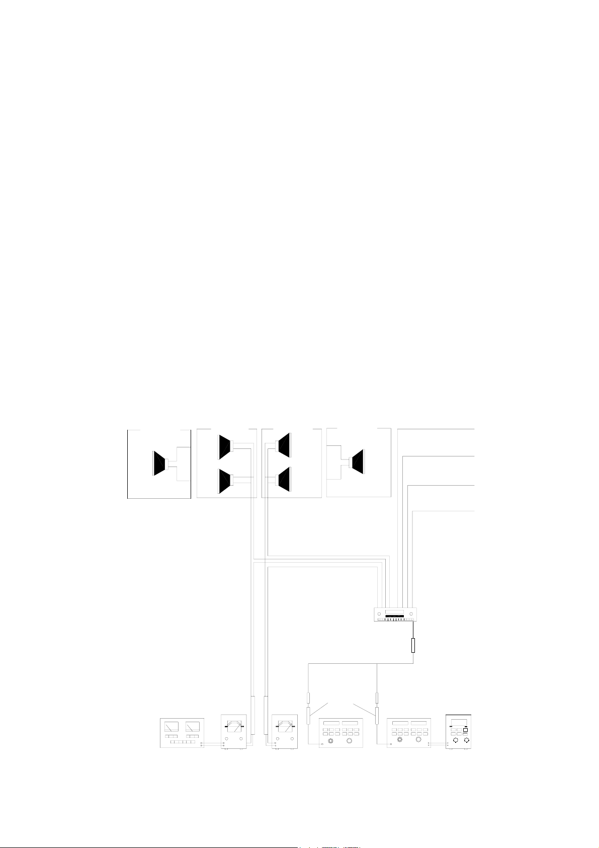
OPERATION CHECK
GENERAL SPECIFICATIONS OF SIGNAL
Standard frequency
Signal output
Modulation
FM
MW
LW
FM
MW
LW
MW
FM Stereo
AF output level FM/MW/LW
Power source voltage DC 14.0V (Backup voltage is the same as this)
AF load impedance 4 ohm pure resistance
Balance Center position of level
Tone Center position
The signal strength read in this section is voltage on the antenna.
Test Diagram
2-SPEAKER
FRONT
SPK.
4-SPEAKER
RL.
SPR.
FL.
SPK.
4-SPEAKER
98.1 MHz (87.5, 108 MHz)
1000 kHz (522, 1620 kHz)
200 kHz (144, 288 kHz)
1mV
5 mV
5 mV
400 Hz 30% MOD.
1 kHz 75kHz DEV.
46% for L only or
R only pilot level 8%
RR.
SPK.
FR.
SPE.
2-SPEAKER
FRONT
SPK.
ACC (DV14.4V)
BACK UP (14.4V)
GROUND
POWER ANTANNA
MAIN UNIT
ANT
DISTORTION
METER
VTVM
VTVM
DUMMY
ANTANNA
AM SG
FM SG
MPX
STEREOS
MODULATOR
5
Page 6

BLOCK DIAGRAM
6
Page 7

FM TUNER BOARD
ALIGNMENT LOCATIONS
7
Page 8

ALIGNMENT PROCEDURES
FM ADJUSTMENT
Equipment Required
z AM IF/RF signal generator
z Solid-state voltmeter (SSVM)
z Regulated DC power supply
z 2-CH voltmeter
z Distortion meter
FM Alignment Using FM Signal Generator
Note: Press the radio power switch to on the radio. Signal generator output must be kept as low as possible
to avoid overload and clipping.
Step Generator
Coupling
Stereo
Separation
FM SNC
Adjustment
Stop
Sens.
Note: The tuner module is well-adjust and adjustment is not recommended.
Signal
Generator
to antenna
receptacle
98.1 MHz
Dev. 75 kHz
L+R=90 %
Int. 1 kHz
60dBµV output
Signal Generator
to antenna
receptacle
Generator Display
98.1 MHz
Int. 1 kHz
Dev. 75 kHz
L+R = 90 %
pilot = 10 %
98.1 MHz
@ 40 dBµ
98.1 MHz
Mod. 1kHz
Dev 75kHz
98.1 MHz VR1
98.1 MHz VR2
98.1 MHz
Setting
Adjustment Remarks
Adjust AF
output power
at maximum
separating
more than 30 dB
Stereo Separation
25 dB (±5 dB)
VR3
Adjust AF to
stop station.
8
Page 9

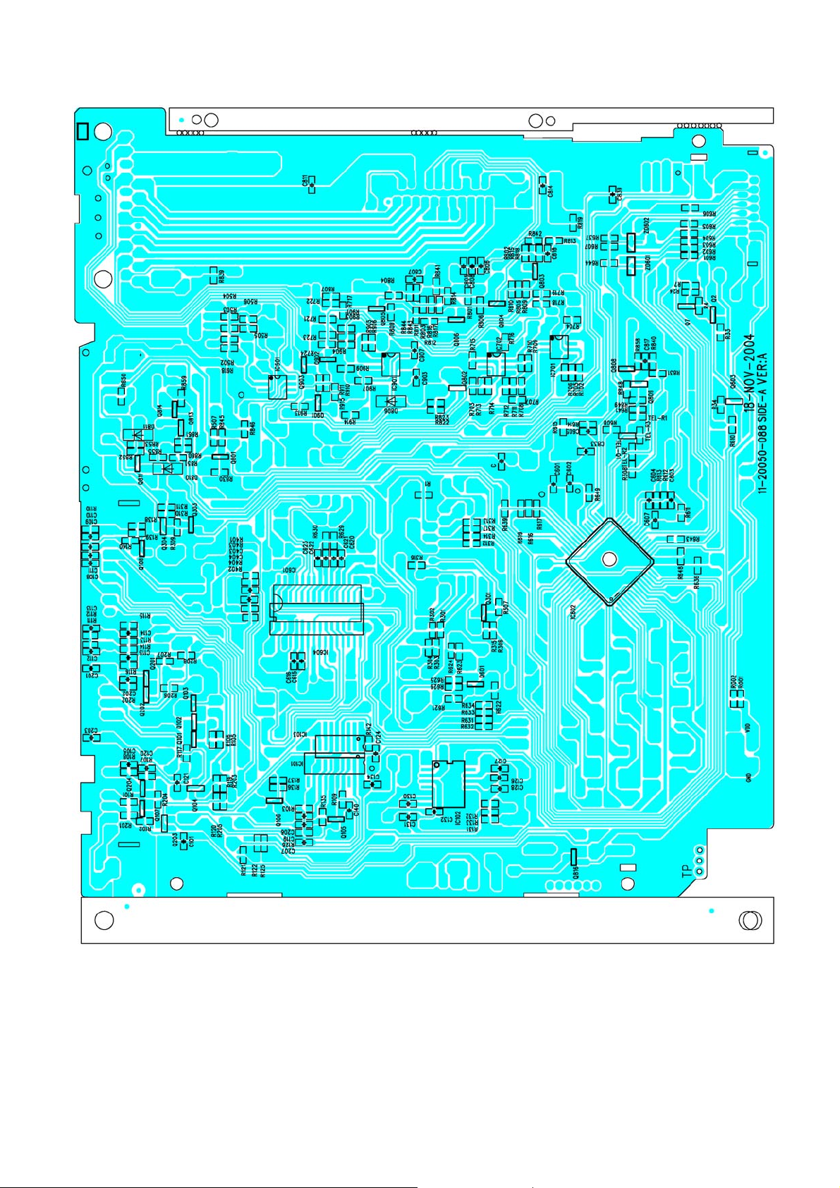
MAIN BOARD
PRINTED CIRCUIT BOARDS
TOP VIEW
9
Page 10
MAIN BOARD
BOTTOM VIEW
10
Page 11
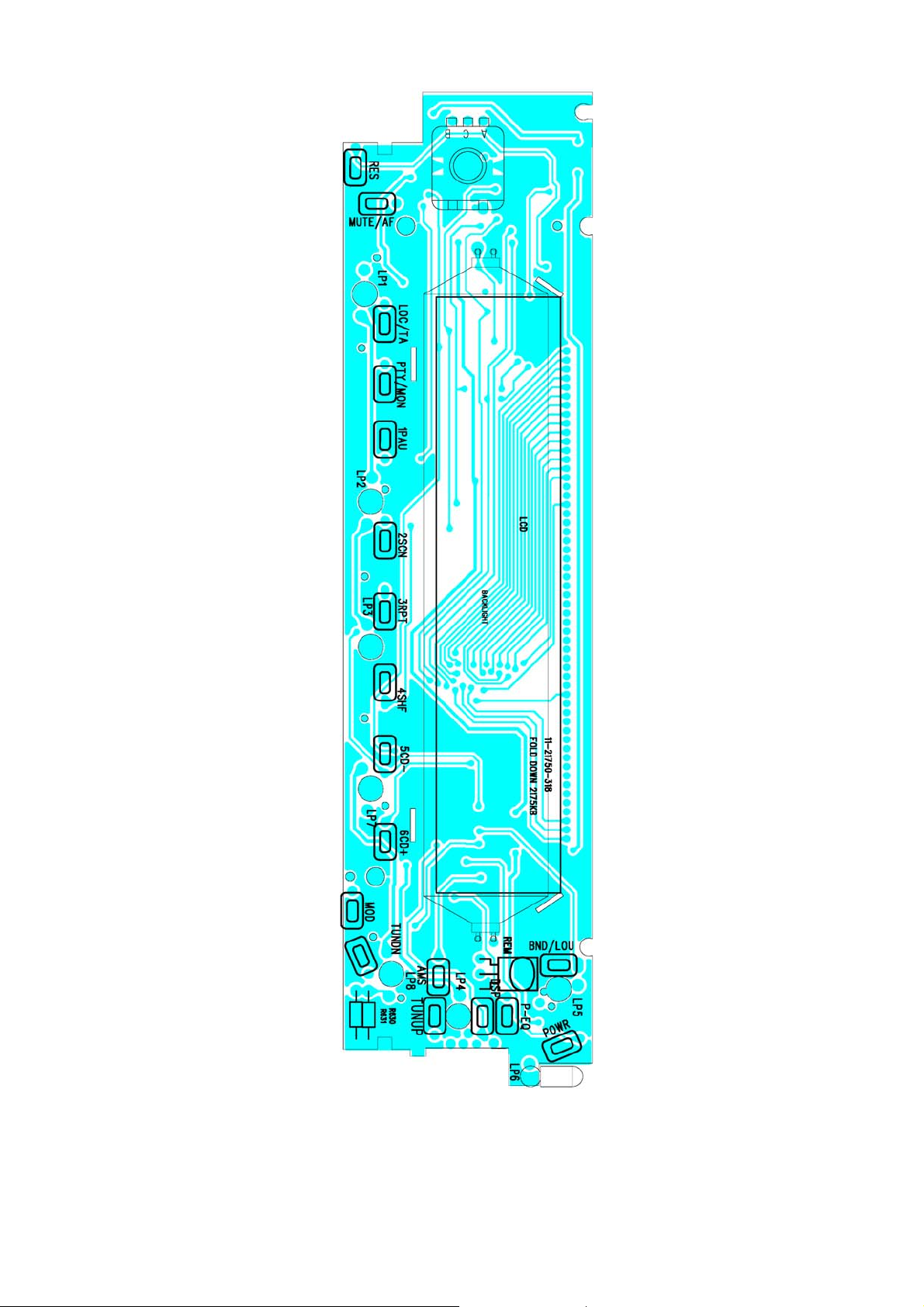
KEY BOARD
TOP VIEW
11
Page 12

KEY BOARD
BOTTOM VIEW
12
Page 13

CD SERVO BOARD
TOP VIEW
13
Page 14

CD SERVO BOARD
BOTTOM VIEW
14
Page 15

REMOTE BOARD
15
Page 16

REMOTE BOARD
16
Page 17

PANEL
EXPLODED VIEW
17
Page 18

EXPLODED VIEW PARTS LIST
PANEL
Ref. No. Description RS Part No. Mfr’s Part No.
1
2
3
4
5
6
7
8
9
10
11
12
13
14
15
16
17
18
19
20
21
22
23
24
25
26
27
28
29
30
31
32
33
34
35
36
37
38
39
Lens; (OPC0000/PMS422C) LCD W/RM X60.16
Panel –F (OP2001/White) LCD X60.16 “USB”
Panel Bottom (F)
VOL Knob (E. Silver)
Round Decoration (E-Silver)
Open Key (L-Up) (OP0000)
RE Knob Spring
Power Knob (L-Up) (OPC0000)
RE Slide Spring
Decoration 01 (OPC0000)
Decoration 02 (OPC0000)
Decoration With USB (S. OPC0000)
USB Cover (Grey)
SET Knob (OPC0000)
AF/TA/PTY Key (L-Up) (OPC0000)
1PAU/3RPT/5 Key (L-Up) (OPC0000)
2SCN/4SHF/6 Key (L-Up) (OPC0000)
MD Key (Crystal/Purple PMS2572C)
Adaptor 01
BND/EQ Key (L-Up) (OPC0000)
0 DSP Key (L-Up) (OPC0000)
8TUNE SKIP/9TUNE SKIP Key (L-Up) (OPC0000)
AMS Key (Crystal/Purple PMS2572C) 2175
Adaptor 02
B-Light 01
B-Light 02
B-Light 03
Key Board
CD115 ROTATE ENCODER VOL
LCD Cover
CD-158USB LCD TN NGE Color Black Mack PIN
LED B.L. QB02002-09 23.5X99 WHT
Axis Post
Right Side Block
Contact Spring
Left Side Block
E-Ring Ø1.5X4X0.4 MM
Screw Ø1.7X4 PH/ST
Screw Ø2X8 BA/ST Black
53-J2122-35Y
51-J2121-31B
51-J2137-00
52-J2130-90E
52-J2131-90E
52-J2147-30
36-11852-00
52-J2135-01
36-11851-00
52-J2133-30
52-J2136-30
52-J2141-31W
52-J2063-01
52-J2134-30
52-J2124-01
52-J2125-01
52-J2126-01
52-C2536-51P
52-J2138-00
52-J2129-01
52-J2128-01
52-J2127-01
52-C2537-52P
52-J2140-00
52-J2142-00
52-J2143-00
52-J2145-00
11-21750-318
18-00115-00
39-E2104-01
27-01581-01Y
02-A1560-09
34-24601-00
52-E2128-00
36-78008-00
52-E2129-00
35-00001-00
40-11704-00
40-12008-21
18
Page 19

CABINET
EXPLODED VIEW
19
Page 20

EXPLODED VIEW PARTS LIST
CABINET
Ref. No. Description RS Part No. Mfr’s Part No.
1
2
3
4
5
6
7
8
9
10
11
12
13
14
15
16
17
18
19
20
21
22
23
24
25
26
27
28
29
30
31
32
33
34
35
36
37
38
39
40
Panel
Ring (S. OP2001)
Base (PC)
Side Bracket (CD200/Wire)
CD MECH. CDM-1683EUK W/O Bracket (143A)
Heat Sink (For Wire)
Top Cabinet
Bottom Cabinet (For Wire)
Main Fiber
Main Board
Mounting Box (072)
Shade
CD Windows Sheet
Hook Shaft
Hook Spring
Hook
Push Out Spring
Panel Pole
Base Back Light
Front Board
20PIN Socket
EJ Knob (L-Up) (S. OPC0000) (L-Up)
Eject Board
Right Bracket
Damper Gear Ass’y /19-24 T/Q
Middle Gear (F)
Left Bracket
Deck Front Bracket
Deck Rear Bracket
MITSUMI TUNER FAE-347-A29
FM Cover
IC Bracket (7805)
Spring Sheet
Heat Sink (7809/DB435) W/O Shaft
Wire Clip 1.0MM
Screw Ø5X18 HH
Spring Washer M5
Hexagon Nut M5
Screw Ø2X3 CH/MA Black
Screw Ø2X4 BH/MS Black
51-G2121-30G
51-E2124-00P
61-E2005-04
94-01683-11
61-E2006-00
61-B0105-01
61-B0114-01
35-B0101-00
11-20050-089
61-07211-03
81-69005-02
43-E2001-00
34-D2101-00
36-E2101-00
52-E2127-00
36-E2102-00
52-E2126-00
52-H2152-00W
11-21740-348
25-F0217-20
52-E2134-01
11-21740-348
39-E2101-01
93-12246-01
52-E2130-00
39-E2102-01
39-E2105-00
39-B0101-00
29-00347-02
39-D0507-00
39-B0115-00
39-B0102-00
39-B0113-01
39-B1415-00
40-05018-04
35-50001-00
35-40005-00
40-12003-09H
40-12004-21
20
Page 21

Ref. No. Description RS Part No. Mfr’s Part No.
41
42
43
44
45
46
47
48
Screw Ø2X6 PA/ST Black
Screw Ø2.6X4 BH/MS
Screw Ø2.6X5 BH/TAPTITE
Screw Ø2.6X6 BH/MS
Screw Ø2.6X6 PH/MS Black
Screw Ø2.6X8 BH/MS
Screw Ø2.6X10 BH/MS
Screw M2.6X20 PH/MS
40-12006-20
40-02604-01
40-02605-03
40-02606-01
40-02606-20
40-02608-01
40-02610-01
40-02620-00
21
Page 22

EXPLODED VIEW (DECK)
22
Page 23

EXPLODED VIEW PARTS LIST (DECK)
Ref. No. Description Parts No. Q’ty
1
2
3
4
5
6
7
8
9
10
11
12
13
14
15
16
17
18
19
20
21
22
23
24
25
26
27
28
29
30
31
32
33
34
35
36
37
38
39
SENSOR
SENSOR PCB
SCREW
COVER-UPPER
LEVER DISC
GUIDE UP
BUSHING ROLLER
ROLLER DISC
SHAFT ROLLER
PIN ROLLER
PVC CAP
B/K ROLLER
PIN PULLEY
PIN IDLE
GEAR IDLE
GEAR PULLEY
BELT PULLEY
GEAR ROLLEY
LOCKER (L)
CAM (L)
S/P CAM (L)
S/P RACK
CAM (R)
LOCKER ®
GEAR RACK
GEAR LOAD ©
GEAR LOAD (D)
GEAR LOAD (B)
GEAR LOAD (A)
PIN LOAD
B/K GEAR
MOTOR
GEAR WORM
SERVO PCB ASSY
SPECIAL SCREW
S/P RO (L)
SUPPORT DAMPER
S/P RO ®
CHASSIS MAIN
ST-23G
FR
CA/H 0” TT 2*3
SECC T1.0
POM (F20-03)
POM (F20-03)
POM (F20-03)
SLICON
SUS 303
SUM24L-NI (PLATE)
PVC
SECC T1.0
SUM24L-NI (PLATE)
SUM24L-NI (PLATE)
POM (F20-03)
POM (F20-03)
CR-WRT
POM (F20-03)
POM (F20-03)
POM (F20-03)
SUS304WPB
SUS304WPB
POM (F20-03)
POM (F20-03)
POM (F20-03)
POM (F20-03)
POM (F20-03)
POM (F20-03)
POM (F20-03)
SUM24L-NI (PLATE)
SECC T1.0
FF-050SH-11190
POM (F20-03)
GLASS EPOXY 1.2T
P/H TTS 2*2
SUS304WPB
POM (F20-03)
SUS304WPB
SEEC T1.0
2
1
12
1
1
1
2
2
1
1
2
1
1
1
1
1
1
1
1
1
1
1
1
1
1
1
1
1
1
4
1
1
1
1
4
1
3
1
1
23
Page 24

EXPLODED VIEW PARTS LIST - CONTINUED (DECK)
Ref. No. Description Parts No. Q’ty
40
41
42
43
44
45
46
47
48
49
50
51
52
53
54
55
56
57
58
59
60
61
62
63
64
65
66
67
68
69
70
71
72
73
CLAMP DISC
HOLD CLAMPER
S/P CLAMPER
TURN TABLE
BASE PU
PIN SIDE (A)
SCREW
PIN SIDE (B)
DAMPER
S/P BASE
MOTOR
GEAR PU (B)
GEAR PU (A)
SCREW
MOTOR
HOUSING GEAR
SHAFT PU
SCREW
4P CONT WIRE
SPRING TENSION
GEAR PU ©
LEAD SCREW
SWITCH
SCREW
PICK UP
FPC WIRE
SPRING PU
FIBER PAPER
S/P CAM ®
TRANSIT SCREW
INSULATOR COVER
SWITCH
WASHER PE
S/P BASE ®
POM (F20-03)
SECC T1.0
SUS304WPB
ABS G/F 20%
POM (F20-03)
SUM24L-NI (PLATE)
CA/H 0” M/S 1.7*2.5
SUM24L-NI(PLATE)
BUTHYL
SUS304WPB
RF-400CA-12265
HYTRELL 5526
POM (F20-03)
CA/H 0” M/S 2*2
FF-050SH-11190
POM (F20-03)
KNN11 (PCD18)
R/H (W/W) TTB2*5
1007 #28
SUS304WPB
POM (F20-03)
BSBM
SW-110
B/H TTB1.7*8
SF-C99
POLY AMIDE
SUS T0.2
0.55
4.5*18
PE
SW-111
PE
SUS304WPB
1
1
1
1
1
2
2
2
1
2
1
1
1
6
1
1
1
1
1
1
1
1
1
1
1
1
1
1
1
2
1
1
2
2
24
Page 25

SCHEMATIC DIAGRAM (MAIN BOARD)
25
Page 26

SCHEMATIC DIAGRAM (KEY BOARD)
26
Page 27

SCHEMATIC DIAGRAM (CD SERVO BOARD)
27
Page 28

SCHEMATIC DIAGRAM (REMOTE BOARD)
28
Page 29

ELECTRICAL PARTS LIST
Ref. No. Part No. Description Q’ty
PC BOARD ASSY, MAIN BOARD
Q801
Q817
Q104,802/9
Q812
Q105~7,601,801/3~6/8,811/6
IC802
Q807
ZD601/2
D802
D601,617,624/6,641/5/7,803/5/6/9
D808,810/1
D801
ZD802
ZD803
IC601
IC701/2
IC602
IC603
IC801
IC804
IC803
IC101
XT601
C134,140,603/4,805~8
C207
C108,110/1,607,811/8,833/9
C112/3
C119,124
C101/5/9,605,817
C620~3
C601
C615/6
C602
C814
C107,123,606,617,816,834/8
C702,835
C102,125,608,629,813
C106,809,812
C836/7
01-00435-00S
01-00435-00S
01-00812-00
01-01240-00
01-03875-07
01-07805-00
01-08550-03
02-00062-07
02-04001-00
02-04148-00A
02-04148-02
02-05401-00
02-50036-00A
02-50100-00A
03-02313-00
03-04558-16
03-05802-001
03-07035-00
03-07384-00
03-07805-00
03-07818-00
03-09257-00
04-00072-01H
05-63102-01
05-63103-01
05-63104-01
05-63153-01
05-63220-00
05-63223-01
05-63224-01
05-63270-00
05-63272-01
05-63300-00
05-63474-02
06-10107-01
06-10227-01
06-10476-01
06-16106-01
06-16107-01
TR. BD435 TO-126 FAIRCHLD
TR. BD436 PNP TO-126 SAMSUNG
TR. 2SA812
TRANSISTOR B1240
TRANSISTOR 2SC3875G
IC-REGULATOR 78L05
TR. 8550C TO-92-B
E.S.D. DIODE NNCD6.2G (5PIN)
DIODE IN4001
DIODE 1N-4148 AT. (TAPPING)
DIO CHIP RLS4148 1206 ROHM
DIODE IN5401
ZENER DIODE 3.6V 0.5W AT. ±2%
ZENER DIODE 10V 0.5W AT. TAPE ±2%
I.C. PT2313L
I.C. BA-4558F
CPU RS5802-001 CD+USB+MMC+RDS
IC KIA7035P
I.C. TDA7384A (4X40W) “Y”
REGULATOR L7805CV (GROUND TAP)
REGULATOR LC-78L18
I.C. TC-9257F
CRYSTAL 702MHZ HC-49U/S 22PF
CHIP 1000PF ±10% X7R 0603 SMT
CHIP 0.01µF ±10% X7R 0603 SMT
CHIP 0.1µF ±10% X7R 0603 SMT
CHIP 0.015µF ±10% X7R 0603 SMT
CHIP CAP 22PF ±5% NPO 0603 SMT
CHIP 0.022µF ±10% X7R 0603 SMT
CHIP 0.22µF ±10% X7R 0603 SMT
CHIP CAP 27PF ±5% NPO 0603 SMT
CHIP 2700PF ±10% X7R 0603 SMT
CHIP CAP 30PF ±5% NPO 0603 SMT
CHIP CAP 0.47µF ±20% X7R 0603 SMT
E. CAP 100µF 10V (Ø5X7MM MINI)
E. CAP 220µF 10V (Ø6MM MINI)
E. CAP 47µF 10V (Ø4X7 MINI)
E. CAP 10µF 16V Ø4X7MM
E. CAP 100µF 16V (Ø6.3X7MM)
1
1
3
1
12
1
1
2
1
11
3
1
1
1
1
2
1
1
1
1
1
1
1
8
1
8
2
2
5
4
1
2
1
1
8
2
5
3
2
29
Page 30

ELECTRICAL PARTS LIST - CONTINUED
Ref. No. Part No. Description Q’ty
C618,819
C701
C810
C116/7,122,610/1,801~4
C614/9,624~7,631/2,703~6
C612/3
C815
C609
R640
R134,854
R620,701
R118
R820,832/7
R642/7
R645/6
R827
R829
R627/8
R600
R129,130,JMP139
R124,825,847
R1,639,644,855
R103
R603
R101,120,601/5,716~9,852
R102/9,119,623/5,631/2,801~4,823,831/9,
841~5/8,851/3
R819,822
R612/3/6/9,636/7,648
R818
R830
R814~7
R121,615,633/4
R702/3,805~8,813,858
R614,626,649
R704/9,710/5
R108
R113/4,629,630,643
R607
R135,140,850
R122,602/4/6,611,840
06-16226-01
06-16227-01
06-16338-00S
06-50105-01
06-50225-01
06-50334-01
06-50335-01
06-50474-01
07-05022-10
07-05100-00
07-05100-16A
07-05101-16A
07-05103-16A
07-05105-16A
07-05220-16A
07-05222-16A
07-05223-16A
07-05394-16
07-05470-16A
07-05472-16A
07-05473-16A
07-63000-00
07-63100-00
07-63101-00
07-63102-00
07-63103-00
07-63104-00
07-63105-00
07-63152-00
07-63182-00
07-63184-00
07-63222-00
07-63223-00
07-63224-00
07-63273-00
07-63331-00
07-63332-00
07-63334-00
07-63471-00
07-63472-00
E. CAP 22µF 16V (Ø4X7MM)
E. CAP 220µF 16V (Ø6.3X12MM)
E. CAP 3300µF 16V 105°C
E. CAP 1µF 50V (Ø4X7 MM)
E. CAP 2.2µF 50V (Ø4X7 MM)
E. CAP 0.33µF 50V Ø4X7MM
E. CAP 3.3µF 50V (Ø4X7MM)
E. CAP 0.47µF 50V Ø4X7MM
RES. 2.2Ω 1/2W
RES. 10Ω 1/4W
RES. 10Ω 1/16W (TAPPING)
RES. 100Ω 1/16W (TAPPING)
RES. 10kΩ 1/16W (TAPPING)
RES. 1MΩ 1/16W (TAPPING)
RES. 22Ω 1/16W (TAPPING)
RES. 2.2kΩ 1/16W (TAPPING)
RES. 22kΩ 1/16W (TAPPING)
RES. 390kΩ 1/16W ±5%
RES. 47Ω 1/16W (TAPPING)
RES. 4.7kΩ 1/16W (TAPPING)
RES. 47kΩ 1/16W (TAPPING)
CHIP RES. 0Ω ±5% 0603 SMT
CHIP RES. 10Ω ±5% 0603 SMT
CHIP RES. 100Ω ±5% 0603 SMT
CHIP RES. 1kΩ ±5% 0603 SMT
CHIP RES. 10kΩ ±5% 0603 SMT
CHIP RES. 100kΩ ±5% 0603 SMT
CHIP RES. 1MΩ ±5% 0603 SMT
CHIP RES. 1.5kΩ ±5% 0603 SMT
CHIP RES. 1.8kΩ ±5% 0603 SMT
CHIP RES. 180kΩ ±5% 0603 SMT
CHIP RES. 2.2kΩ ±5% 0603 SMT
CHIP RES. 22kΩ ±5% 0603 SMT
CHIP RES. 220kΩ ±5% 0603 SMT
CHIP RES. 27kΩ ±5% 0603 SMT
CHIP RES. 330Ω ±5% 0603 SMT
CHIP RES. 3.3kΩ ±5% 0603 SMT
CHIP RES. 330kΩ ±5% 0603 SMT
CHIP RES. 470Ω ±5% 0603 SMT
CHIP RES. 4.7kΩ ±5% 0603 SMT
2
1
1
9
12
2
1
1
1
2
2
1
3
2
2
1
1
2
1
3
3
4
1
1
9
22
2
7
1
1
4
4
8
3
4
1
5
1
3
6
30
Page 31

ELECTRICAL PARTS LIST - CONTINUED
Ref. No. Part No. Description Q’ty
R125/6,608,641,706/7,712/3,823,846/7/9
R622
R809~12
R624
R716~9
R705/8,711/4
R621
L803
JMP102
MB
L801
PC BOARD ASSY, FM TUNER BOARD
Q101~3,204
D101
IC102
XT101
C120/1,132
C128,131
C126
C127
C130
C114/5
C118
C133
R104
R141
R132/3
R131
R105,117
R106
R107
R204
R111/2
TUNER
PC BOARD ASSY, AM TUNER BOARD
Q203
Q201/2
D641/4/6
C208
C206
07-63473-00
07-63512-00
07-63561-00
07-63752-00
07-63821-00
07-63822-00
07-63823-00
09-70100-01
09-70470-04
11-20050-089
15-27012-11
01-03875-07
02-04148-00A
03-06579-00
04-00433-00M.
05-63103-01
05-63223-01
05-63330-00
05-63470-00
05-63681-00
05-63682-01
06-10476-03
06-50224-02
06-50225-02
07-05101-16A
07-05222-16A
07-63100-00
07-63101-00
07-63102-00
07-63151-00
07-63471-00
07-63473-00
07-63562-00
29-00347-02
01-00812-00
01-03875-07
02-04148-00A
05-16225-00
05-63103-01
CHIP RES. 47kΩ ±5% 0603 SMT
CHIP RES. 5.1k ±5% 0603 SMT
CHIP RES. 560Ω ±5% 0603 SMT
CHIP RES. 7.5kΩ ±5% 0603 SMT
CHIP RES. 820Ω ±5% 0603 SMT
CHIP RES. 8.2kΩ ±5% 0603 SMT
CHIP RES. 82kΩ ±5% 0603 SMT
MICRO INDUCTOR 10UH AXIAL TYPE
M. INDUCTOR AL03T04R7 (AXIAL)
CD200Y (USB) 182X152X1.6MM
RING COIL Ø27X12MM V-TYPE (XC-169-110µH)
TRANSISTOR 2SC3875G
DIODE IN-4148 AT. (TAPPING)
IC SAA-6579T
C. 4.332MHZ HC-49U 30PPM 22PF
CHIP 0.01µF ±10% X7R 0603 SMT
CHIP 0.022µF ±10% X7R 0603 SMT
CHIP CAP 33PF ±5% NPO 0603 SMT
CHIP CAP 47PF ±5% NPO 0603 SMT
CHIP CAP 680PF ±5% NPO 0603 SMT
CHIP 6800PF ±10% X7R 0603 SMT
E. CAP 47µF 10V (6X5)
E. CAP 0.22µF 50V (Ø3X5MM)
E. CAP 2.2µF 50V (4X5)
RES. 100Ω 1/16W (TAPPING)
RES. 2.2kΩ 1/16W (TAPPING)
CHIP RES 10Ω ±5% 0603 SMT
CHIP RES 100Ω ±5% 0603 SMT
CHIP RES 1kΩ ±5% 0603 SMT
CHIP RES 150Ω ±5% 0603 SMT
CHIP RES 470Ω ±5% 0603 SMT
CHIP RES 47kΩ ±5% 0603 SMT
CHIP RES 5.6kΩ ±5% 0603 SMT
MITSVMI TUNER FAE-347-A29
TR. 2SA812
TRANSISTOR 2SC3875G
DIODE IN-4148 AT. (TAPPING)
TAN CAP. 2.2µF 16V
CHIP 0.01µF ±10% X7R 0603 SMT
13
1
4
1
4
4
1
1
1
1
1
4
1
1
1
3
2
1
1
1
2
2
1
1
1
1
2
1
2
1
1
1
2
1
1
2
3
1
1
31
Page 32

ELECTRICAL PARTS LIST - CONTINUED
Ref. No. Part No. Description Q’ty
C201~3
C204
R209
R205/7/8
R201/3
R202
R206
L201
ZD601
DLP1~8
ZD602/3
IC601
C601
C603
R630/1
R621/5
R624
R610 (PTY)
R622
R613
R604,616
R605,617,633
R609,623
R606,618
R626
R628
R619,607(TA)
R643
R603
R636/A,639/A
R620
R644
KB
USB BOARD
SW
POWER
05-63223-01
06-16106-02E
07-05100-16A
07-63102-00
07-63103-00
07-63331-00
07-63822-00
09-70470-04
PC BOARD ASSY, KEY BOARD
02-00062-07
02-A1560-09
02-30553-60T
02-50051-00A
03-75823-00
05-63223-01
05-63681-00
07-05101-00
07-63102-00
07-63103-00
07-63122-00
07-63152-00
07-63153-00
07-63181-00
07-63221-00
07-63222-00
07-63331-00
07-63333-00
07-63391-00
07-63471-00
07-63473-00
07-63513-00
07-63561-00
07-63681-00
07-63823-00
11-21750-318
11-21750-338
16-01107-00K
16-01140-04
CHIP 0.022µF ±10% X7R 0603 SMT
E. CAP. 10µF/16V (4X5MM RC3)
RES 10Ω 1/16W (TAPPING)
CHIP RES 1kΩ ±5% 0603 SMT
CHIP RES 10kΩ ±5% 0603 SMT
CHIP RES 330Ω ±5% 0603 SMT
CHIP RES 8.2kΩ ±5% 0603 SMT
M. INDUCTOR AL03TO4R7 (AXIAL)
E.S.D. DIODE NNCD6.2G (5PIN)
LED B.LIGHT QB02002-09 23.5X99 WHT
P. LAMP AA 3V 60MA Ø3X5.5 K.T.
ZENER DIODE 5.1V 0.5W AT. ±2%
IC LC75823ED
CHIP 0.022µF ±10% X7R 0603 SMT
CHIP 680PF ±5% NPO 0603 SMT
RES 100Ω 1/4W
CHIP RES 1kΩ ±5% 0603 SMT
CHIP RES 10kΩ ±5% 0603 SMT
CHIP RES 1.2kΩ ±5% 0603 SMT
CHIP RES 1.5kΩ ±5% 0603 SMT
CHIP RES 15kΩ ±5% 0603 SMT
CHIP RES 180Ω ±5% 0603 SMT
CHIP RES 220Ω ±5% 0603 SMT
CHIP RES 2.2kΩ ±5% 0603 SMT
CHIP RES 330Ω ±5% 0603 SMT
CHIP RES 33kΩ ±5% 0603 SMT
CHIP RES 390Ω ±5% 0603 SM
CHIP RES 470Ω ±5% 0603 SMT
CHIP RES 47kΩ ±5% 0603 SMT
HIP RES 51kΩ ±5% 0603 SMT
CHIP RES 560Ω ±5% 0603 SM
CHIP RES 680Ω ±5% 0603 SMT
CHIP RES 82kΩ ±5% 0603 SMT
CD-F2175 KB LCD D/S 1.2X180X42.5MM
CD-2175 USB BOARD 1.2X18X7.0MM
TACT SW. DCT/1101 4.3MM 2 PIN
TACT SW. KPS-1107SW H=2.5 KIE SMD
3
1
1
3
2
1
1
1
1
1
8
2
1
1
1
2
2
1
1
1
1
2
3
2
2
1
1
2
1
2
4
1
1
1
1
17
1
Q4
Q3
PC BOARD ASSY, SDK/CD SERVO BOARD
01-00103-00
01-00103-01
TR. KRC103S
TR. KEC A103S PNP SOT-23
32
1
1
Page 33

ELECTRICAL PARTS LIST - CONTINUED
Ref. No. Part No. Description Q’ty
Q305
Q2,304
Q1
Q301/3
SD1,2
D1
ZD1
D2~7
ZD301
U1
U7
U3
U4
U6
U5
U2
Y1
X1
EC9,10
EC5~8,11~7
C31
C30
C50
C58,60,76/8
C24,77/9
C26,44,52
C1~16/8~20,32~40/3/5~9,51/3/4/7,62~4,7
0/5,81~5/7~92
C21/7~9,71/2
C23
C66/7
C17
C80
C41/2,55/6
C65
C22
C25
C303/4
EC1~4
01-00435-00S
01-00812-00
01-01225-13
01-03875-07
02-00144-00
02-04148-00A
02-50036-00
02-50062-54
02-50091-00A
03-00760-00
03-01642-00
03-05341-00
03-09004-00
03-16161-00
03-39800-00
03-63712-00
04-00120-02
04-00169-00
05-16105-00
05-16106-10
05-63020-00
05-63030-00
05-63100-00
05-63101-00
05-63102-01
05-63103-01
05-63104-01
05-63152-01
05-63200-00
05-63220-00
05-63223-01
05-63224-01
05-63330-00
05-63361-00
05-63470-00
05-63561-00
06-10107-02
06-16107-54
TR. BD435 NPN TO-126 SAMSUNG
TR. 2SA812
TRANSISTOR 2SD1225M
TRANSISTOR 2SC3875G
IR LED MIE 144A1MC
DIODE IN-4148 AT. (TAPPING)
ZENER DIODE 3.6V ±5% 0.5W
ZENER DIODE SMD 6.2V (LLDS) 1206
ZENER DIODE 9.1V ±5% 0.5W AT.
USB+MMC (SD) DSP TCC760 TQFP-128 TELECHIPS
VOLTAGE LDO REGULATOR IC IP1642L INTERPION
A/D CONVERTER IC CS5341-DZZ CIRRUS LOGIC
IC 5-CH MOTOR DRIVER IP9004 INTERPION
1MX16 SDRAM HU57V161610ET-71 TSOP-50 HYNIX
SST FLASH 39VF 800A-70-4I-EK TSOP-48
IC µPD 637120NEC LQFP100
CRYSTAL HC-49/US 12MHZ
CRYSTAL HC-49/US 16.9344MHZ
TAN CAP 10UF 16V ±10%
TAN CAP 10UF 16V ±10% 1206 SMD
CHIP CAP 2PF ±5% NPO 0603 SMT
CHIP CAP 3PF/50V ±5% NPO 0603 SMT
CHIP CAP 10PF ±5% NPO 0603 SMT
CHIP 100PF ±5% NPO 0603 SMT
CHIP 1000PF ±10% X7R 0603 SMT
CHIP 0.01µF ±10% X7R 0603 SMT
CHIP 0.1µF ±10% X7R 0603 SMT
CHIP 1500PF ±10% X7R 0603 SMT
CHIP CAP 20PF ±5% NPO 0603 SMT
CHIP CAP 22PF ±5% NPO 0603 SMT
CHIP 0.022µF ±10% X7R 0603 SMT
CHIP 0.22µF ±10% X7R 0603 SMT
CHIP CAP 33PF ±5% NPO 0603 SMT
CHIP 360PF ±10% 0603 SMT
CHIP CAP 47PF ±5% NPO 0603 SMT
CHIP 560PF ±5% NPO 0603 SMT
E. CAP 100µF 10V (6X5) SUPER MINI
E. CAP CHIP 100µF 16V Ø6.3X5.5
1
2
1
1
2
1
1
6
1
1
1
1
1
1
1
1
1
1
2
11
1
1
1
4
3
3
54
6
1
2
1
1
4
1
1
1
2
4
33
Page 34

ELECTRICAL PARTS LIST - CONTINUED
Ref. No. Part No. Description Q’ty
C301/2
R5
R305
R12,33,64/5,86/7,110/3
R26/7
R42/3
R47
R39,93/4
R125~7
R36,62/7/8,71~6,104,309
R7~11/4~9,23~5/9~32,88,100,120,310/7
R66/9,70,80,95,316
R48
R106
R111
R21/2
R55,97/8
R107,121
R101
R6,311
R117~9,303/4
R307
R112
R34/5
R37,40/4,52/3/6,84,91
R308
R301/2
R63,90
R81/3/5/9
R46,105,312~4
R28,45,77,108,315
R114
R57
R13,20
R127
R306
R50/1,102/3
R92
BD3,4
06-50225-02
07-05047-00
07-05103-16A
07-63000-00
07-63015-00
07-63030-00
07-63051-00
07-63100-00
07-63101-00
07-63102-00
07-63103-00
07-63104-00
07-63105-00
07-63106-00
07-63121-00
07-63122-00
07-63153-00
07-63183-00
07-63203-00
07-63221-00
07-63222-00
07-63223-00
07-63224-00
07-63303-00
07-63333-00
07-63334-00
07-63392-00
07-63393-00
07-63471-00
07-63472-00
07-63473-00
07-63474-00
07-63475-00
07-63512-00
07-63563-00
07-63562-00
07-63752-00
07-63823-00
09-31601-00
E. CAP 2.2µF 50V (4X5)
RES. 4.7Ω 1/4W
RES. 1kΩ 1/16W (TAPPING)
CHIP RES 0Ω 0603 SMT
CHIP RES 1.5Ω 0603 SMT
CHIP RES 3.0Ω ±5% 0603 SMT
CHIP RES 5.1Ω ±5% 0603 SMT
CHIP RES 10Ω ±5% 0603 SMT
CHIP RES 100Ω ±5% 0603 SMT
CHIP RES 1kΩ ±5% 0603 SMT
CHIP RES 10kΩ ±5% 0603 SMT
CHIP RES 100kΩ ±5% 0603 SMT
CHIP RES 1MΩ ±5% 0603 SMT
CHIP RES 10MΩ ±5% 0603 SMT
CHIP RES 120Ω ±5% 0603 SMT
CHIP RES 1.2kΩ ±5% 0603 SMT
CHIP RES 15kΩ ±5% 0603 SMT
CHIP RES 18kΩ ±5% 0603 SMT
CHIP RES 20kΩ ±5% 0603 SMT
CHIP RES 220Ω ±5% 0603 SMT
CHIP RES 2.2kΩ ±5% 0603 SMT
CHIP RES 22kΩ ±5% 0603 SMT
CHIP RES. 220kΩ ±5% 0603 SMT
CHIP RES. 30kΩ ±5% 0603 SMT
CHIP RES 33kΩ ±5% 0603 SMT
CHIP RES. 330kΩ ±5% 0603 SMT
CHIP RES 3.9kΩ ±5% 0603 SMT
CHIP RES 39kΩ ±5% 0603 SMT
CHIP RES 470Ω ±5% 0603 SMT
CHIP RES 4.7kΩ ±5% 0603 SMT
CHIP RES. 47kΩ ±5% 0603 SMT
CHIP RES 470kΩ ±5% 0603 SMT
CHIP RES 4.7MΩ ±5% 0603 SMT
CHIP RES 5.1kΩ ±5% 0603 SMT
CHIP RES 56kΩ ±5% 0603 SMT
CHIP RES. 5.6kΩ ±5% 0603 SMT
CHIP RES. 7.5kΩ ±5% 0603 SMT
CHIP RES 82kΩ ±5% 0603 SMT
EMIFIL (SMD) BLM319601SG
2
1
1
8
2
2
1
3
3
12
23
6
1
1
1
2
3
2
1
2
5
1
1
2
8
1
2
2
4
5
5
1
1
2
1
1
4
1
2
34
Page 35

ELECTRICAL PARTS LIST - CONTINUED
Ref. No. Part No. Description Q’ty
SW1
Q500
LD901
D500/1
IC500
C500
C501/2
R501
R500
R601
R619
R641
CF501
C707/8
R721/2
RCA
12-05802-120
16-00033-01
PC BOARD ASSY, REMOTE BOARD
01-01781-18
02-00334-00
02-04148-00
03-00101-00
05-03105-10M
05-03121-06
07-05022-54
07-05102-54
07-63102-00
07-63105-00
07-63472-00
09-50455-05J
12-93363-818
PC BOARD ASSY, LINE OUT SECTION
06-50105-03
07-63102-00
20-20360-08
PCB CDX3.60.16.4 SERVO D/S 110X101X1.2MM
MICRO SWITCH MPU10371MLBO (MIC)
TR. 2SD178K-R “ROHM”
INFRARED LED Ø3MM MIE-334A4
DIODE IN-4148
IC S0101 (SGNEC)
CHIP CAP KC20E1C105M-TS
CHIP CAP 120PF (NPO)
CHIP RES. 2.2Ω 1/10W
CHIP RES. 1kΩ 1/10W
CHIP RES. 1kΩ ±5% 0603 SMT
CHIP RES. 1MΩ ±5% 0603 SMT
CHIP RES. 4.7kΩ ±5% 0603 SMT
CER RESONATOR ZTB455E
KB RC06 (093X3.6.3) D/S 1.2X80X48
E. CAP 1µF 50V (Ø4X5MM)
CHIP RES 1kΩ ±5% 0603 SMT
RCA CABLE WIRE 360MM GREY
1
1
1
1
2
1
1
2
1
1
1
1
1
1
1
2
2
1
Q815
Q603,813/4
Q1
ZD804
C840
C841
R2
R609
R7,610,861
R1
R4,5
R3
R859
R6
EJ
PC BOARD ASSY, FRONT BOARD
01-00435-00S
01-03875-07
01-08050-03
02-0112-06M
02-30000-12
02-30703-40J
02-50100-00A
06-16226-01
06-16476-01
07-05221-00
07-05222-16A
07-63103-00
07-63104-00
07-63222-00
07-63393-00
07-63471-00
07-63472-00
11-21760-348
16-01140-04A
16-51377-00A
TR. BD435 NPN TO-126 FAIRCHLD
TRANSISTOR 2SC3875G
TR. 8050C TO-92-B
SMD LED S172DNB4-5 0805 BLUE
LED Ø3MM RED (WIDE ANGLE)
PLAMP 3V 40MM 3X7 K.T.
ZENER DIODE 10V 0.5W AT. TAPE ±2%
E. CAP 22µF 16V (Ø4X7MM)
E. CAP 47µF 16V (Ø5X7MM)
RES 220Ω 1/4W
RES 2.2kΩ 1/16W (TAPPING)
CHIP RES 10kΩ ±5% 0603 SMT
CHIP RES 100kΩ ±5% 0603 SMT
CHIP RES 2.2kΩ ±5% 0603 SMT
CHIP RES 39kΩ ±5% 0603 SMT
CHIP RES 470Ω ±5% 0603 SMT
CHIP RES 4.7kΩ ±5% 0603 SMT
CDD-F2176 FB/EJ PCB 1.2X81.4X28MM
TACT SW KPS-1107SW TAPPING
PUSH SW SPPB51 “ALPS”
1
3
1
1
1
1
1
1
1
1
1
3
1
2
1
1
1
1
1
1
35
Page 36

SPECIFICATIONS
T. H. D........................................................................................................................................... Less than 0.35%
Signal to Noise Radio ................................................................................................................... More than 60 dB
Channel Separation...................................................................................................................... More than 60 dB
Frequency Response .......................................................................................................................... 20Hz-20kHz
Stereo Separating (FM) .................................................................................................................. 30 dB (at 1kHz)
Signal to Noise Ratio (FM) .......................................................................................................... Better than 50 dB
Output Power............................................................................................................................................. 4 X 40W
Speaker Output Impedance................................................................................................................... 4 To 8 ohm
Power Source ................................................................................................................DC 12V, Negative ground.
Frequency Range ...................................................................................................................... FM 87.5 - 108MHz
.................................................................................................................................................. MW 522 -1620 kHz
..................................................................................................................................................... LW 144 -288 kHz
Sensitivity............................................................................................................................... FM 3 µV (S/N=30dB)
......................................................................................................................................... MW 32 dBµ (S/N=20 dB)
.......................................................................................................................................... LW 35 dBµ (S/N=20 dB)
Specifications are subject to change without notice.
36
 Loading...