


XR-MD100
XR-MD101
U(S),K(S)
EZ(S)
SERVICE MANUAL
• BASIC TAPE MECHANISM : 2ZM-1 YR9 MD/CD STEREO SYSTEM • BASIC CD MECHANISM : 3ZG-3 E3N
• BASIC MD MECHANISM : 7ZG-9 YB
This service manual contains information only on the TEST MODE and ELECTRICAL ADJUSTMENT <CD SECTION> of XR-MD100(U,K)/MD101(EZ).
For more information, please refer to the following service manuals. XR-MD100 U<S> (S/M Code No.09-993-315-0R1)
XR-MD100 K<S>/MD101 EZ<S> (S/M Code No.09-993-315-0R3).
S/M Code No. 09-993-315-0S1
SUPPLEMENTDATA
TEST MODE
1. CD Test Mode
1-1. Starting Up the CD Test Mode
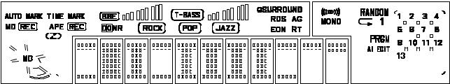
While pressing the “CD” button, connect the AC plug to the power outlet. When the CD test mode starts up, all displays turn on.
1-2. How to Release the CD Test Mode
To release the CD test mode, press the “POWER” button or the function buttons other than the “CD” button, or disconnect the AC plug from the power outlet.
1-3. Function Description of the Test Mode
MODE |
Operation |
Indication on |
Function and movement |
Check item |
|
display |
|||||
|
|
|
|
||
|
|
|
|
|
|
Start mode |
CD key + AC |
All indicators light |
• CD TEST mode starts |
• Check all indicators light |
|
|
plug IN |
|
• All indicators light |
• Microprocessor |
|
|
|
|
|
|
|
Focus search mode |
STOP key |
CD |
• LD lights |
• DATA BUS LINE |
|
|
|
|
• Continuous focus search |
• APC circuit |
|
|
|
|
• Continuous spindle motor |
• LASER current |
|
|
|
|
kick |
• Check the focus search |
|
|
|
|
|
waveform |
|
|
|
|
|
• Check the focus error |
|
|
|
|
|
waveform |
|
|
|
|
|
• Focus servo circuit |
|
|
|
|
|
• DRF output |
|
|
|
|
|
• Spindle servo line |
|
|
|
|
|
|
|
Play mode |
PLAY key |
Track No. and |
• Normal playback |
• Same checks as shown in the |
|
|
|
playing time |
• When TOC reading is not |
above column |
|
|
|
(spectrum analyzer) |
possible, the focus search |
• Each servo circuit |
|
|
|
|
continues |
|
|
|
|
|
|
|
|
Traverse mode |
PAUSE key |
Track No. and |
• Tracking servo is turned off |
• Check the tracking error |
|
|
|
playing time |
|
waveform |
|
|
|
|
|
• Tracking circuit |
|
|
|
|
|
|
|
Sled mode |
F.SKIP key |
CD TEST |
• The pickup moves to the |
• Sled circuit |
|
|
B.SKIP key |
|
innermost track |
• Mechanism (gear and motor) |
|
|
|
|
• The pickup moves to the |
|
|
|
|
|
outermost track |
|
|
|
|
|
|
|
Note: If the focus search operation is continued for 10 minutes or longer, the driver IC heats up sufficiently to trigger the protection circuit, which stops the CD system. Turn off the main power and re-start operation about 10 minutes later.
2. MD Test Mode
2-1. Starting Up the MD Test Mode
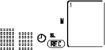
While pressing the “MD” button, connect the AC plug to the power outlet. About one second later after the MD test mode has started up, the following message appears and the MD test mode becomes operable.


 M
M
 D
D


 T
T


 E
E
 S
S
 T
T


Note: 1. If operation of the mechanism shows any abnormality during the test mode, disconnect the AC plug immediately.
2.Playback and recording are not possible during the test mode.
3.If a disc cannot be inserted, insert a disc part way and press the “CD 2 MD DIRECT REC” button. The disc can then be fully inserted.
2

2-2. How to Exit the MD Test Mode
1)Press the “MD EJECT” button and remove the disc.
2)Disconnect the AC plug from the power outlet.
*If the machine exits the MD test mode by any methods other than the procedure described above, the machine may operate abnormally when the POWER is turned on next time. If this happens, disconnect the AC plug.
2-3. Operation Check Mode
1)Checks after the test mode has started up
The following playback audio circuits can be checked.
• |
The circuits that can be checked: ..................... |
DAC, LINE AMP and HEADPHONE AMP |
• |
Output level: .................................................... |
1 kHz, -21 dB |
2)Switch status check
The ON/OFF states of the respective switches on the machine and mechanism can be checked on the display.
Switch Name |
Switch State |
Indication on display |
Usable disc |
|
|
|
|
|
|
REC PROTECT |
When the write-protection tab of a disc is closed to ON |
ROCK |
Disc for record/playback |
|
|
|
|
|
|
REFRECT |
When the high reflection disc (CD) is used |
POP |
Disc for playback only |
|
|
|
|
|
|
INNER |
When the pickup is at the innermost |
JAZZ |
— |
|
track (when the LIMIT switch is ON) |
||||
|
|
|
||
|
|
|
|
3)How to Switch to Servo Standby Mode
When the MD test mode has been established, the mode changes to the servo standby mode and “ALL SV OFF” is displayed by pressing the 9 button. The various check modes can be entered from this mode. Pressing the 9 button during each operation returns to “ALL SV OFF”.
A L L |
S V OF F |
4)Checking the Sled Operation
The operation of the sled motor and pickup can be checked by pressing the 6 (to outermost track) and 5 (to innermost track) buttons in the “ALL SV OFF” state. “T.SLED FWD” appears while moving to the outermost track and “T.SLED RVS” appears while moving to the innermost track.
5)Checking the Laser Output
The laser power output level is switched each time the “MD EDIT” button is pressed when “ALL SV OFF” appears and the operation stops. The laser power output level is repeatedly changed in the order of OFF LASER READ ™ LASER 1/2 ™
LASER WRITE. The indications are as follows.
MODE |
Indication on display |
|
|
|
|
OFF |
ALL SV OFF |
T-BASS |
|
|
|
LASER READ |
LASER READ |
T-BASS |
|
|
|
LASER 1/2 WRITE |
LASER 1/2 |
T-BASS |
|
|
|
LASER WRITE |
LASER WRITE |
T-BASS |
|
|
|
*After checking, press the 9 button to return the display to “ALL SV OFF”.
6)Checking the Operation of OWH (Over Write Head)
The OWH operation can be checked in the loading-completed state.
“MD 2 CD” button ............. |
OWH DOWN |
“ / MD EJECT” button ...... |
OWH UP |
Note: Do not move down the OWH while using a high reflection disc (CD).
3
 Loading...