


XR-M700 K
SERVICE MANUAL
COMPACT DISC |
BASIC TAPE MECHANISM : 2ZM-1 R9NM |
STEREO SYSTEM |
BASIC CD MECHANISM : ZZG-4 YB |
|
|
•This Service Manual contains the additional information “CD MECHANISM DISASSEMBLY INSTRUCTIONS” and “CD TEST MODE” for the model XR-M700 (K).
If requiring the other information, see Service Manual of XR-M700 (K), (S/M Code No. 09-006-430-8R1).
S/M Code No. 09-009-430-8S1
SUPPLEMENTDATA

CD MECHANISM DISASSEMBLY INSTRUCTIONS
1.Procedure of Disassembling the ZZG-4 Mechanism
1-1. Removing the FRAME, MAIN
1)Remove a screw and PLATE, FRAME L.
2) Remove the 2 screws and PLATE, FRAME R.
3)Pull up 1 LEVER, LOCK F, and pull out 2 FRAME, MAIN toward the front. Turn the GEAR, SLIDER B and adjust the ELEVATOR to any position except TOP.
– 2 –

4)Remove the FRAME, MAIN on the L side first. Then lift up toward the direction of the arrow and remove the FRAME, MAIN from the BASE.
1-2. Removing the GEAR, TRAY AB
1) Remove the 2 screws and HLDR, SHAFT.
2)Turn the GEAR, SLIDER B and shift the ELEVATOR to the TOP position.
3)Pull out the GEAR, TRAY AB and SHAFT, ELEVATOR.
– 3 –
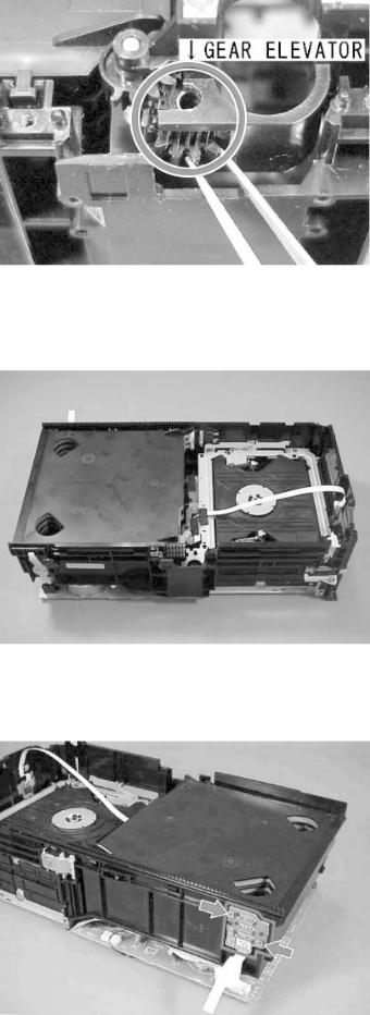
1-3. Removing the GEAR, ELEVATOR
1) Remove the GEAR, ELEVATOR.
1-4. Removing the CD MAGAZINE Part
1)Remove the GEAR, TRAY A and B, etc. to make it look like in the photo.
2) Remove the 2 screws and PWB, TRAY.
– 4 –
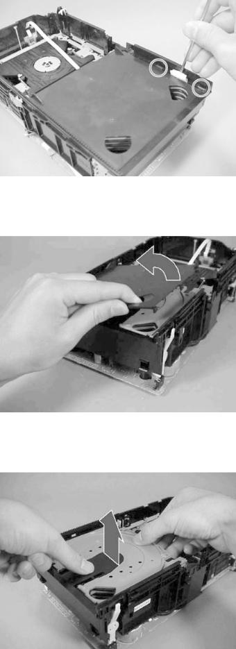
3)Remove the claws indicated by the circles in order to remove the MAGAZINE, TOP. Insert a minus driver into the gap and remove the MAGAZINE, TOP by lifting it upward.
4) Remove the MAGAZINE, TOP.
5)Remove the TRAY 1,2,3 and 3 pieces of MAGAZINE by lifting them up.
– 5 –
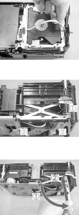
1-5. Removing the ELEVATOR Part
1)Remove the FFC, 4P of the switch circuit board from the BASE rib, and disconnect it from the connector.
2)1Remove the spring (88-ZG5-292-010).
2Remove the 2 screws.
3)1Remove the front side of the HLDR, LINK R from the boss, rotate it as shown in the photo.
2Shift the HLDR, LINK R toward the direction of the arrow as shown in the photo and remove it.
4) Remove the HLDR, LINK L in the same step as R.
– 6 –
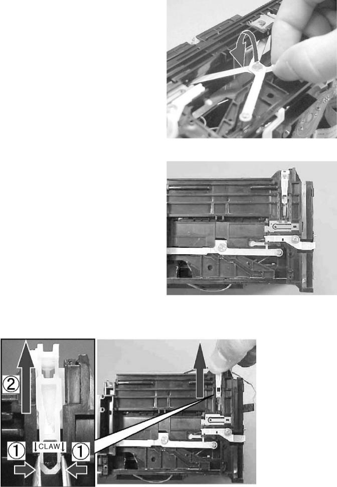
5)Remove the boss of the LEVER, ASSY LINK from the groove of the LEVER SLIDE (both L and R sides).
6) Remove the spring (88-ZG5-225-010).
7) 1Use a pair of tweezers to remove the claw below the 2 LEVER, LOCK F. Then pull out the LEVER LOCK F.
– 7 –

8)1Lift up the PLATE, ELEVATOR, together with the HLDR, CLAMP.
2Once lift it up to the TOP position, pull it toward the front side. Then remove the PLATE, ELEVATOR and HLDR, CLAMP.
9) Views after removing the ELEVATOR part and MAGAZINE part.
* At this stage, the mechanism’s pick-up can be changed. Refer to “5. Procedure of Replacing the Pick-up” for details.
– 8 –
1-6. Removing the ELEVATOR UP/DOWN Components.
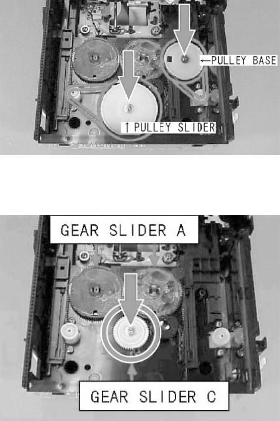
1) Remove the BELT, SLIDER and BELT, BASE. Then remove the 2 screws, the PULLEY, SLIDER and PULLEY, BASE.
2) Remove the screw and GEAR, SLIDER C.
– 9 –

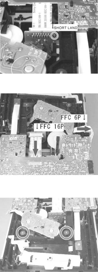
3) Turn over the CD mechanism and short-circuit the shortland of the pick-up.
4)Desolder M201 and M202. And remove the screw.
Disconnect FFC (3 parts) and remove the CD C.B from the BASE.
screw |
– 10 – |
|
5)Views after removing the CD C.B.
Once the claws (indicated by the circles) are pressed, 2 of the GEAR, SLIDER A will come off.
– 11 –
2.Procedure of Replacing the Pick-up
2-1. Removing the Pick-up
1)Turn over the CD mechanism and short-circuit the shotland (indicated by the circle) at the pick-up.
2) Disconnect the FFC, 16P and FFC, 6P.
3)Remove the 2 pieces of the Washer W-P, 2.08-8-0.5 (87-B10-273-010).
– 12 –
 Loading...