

Page 1
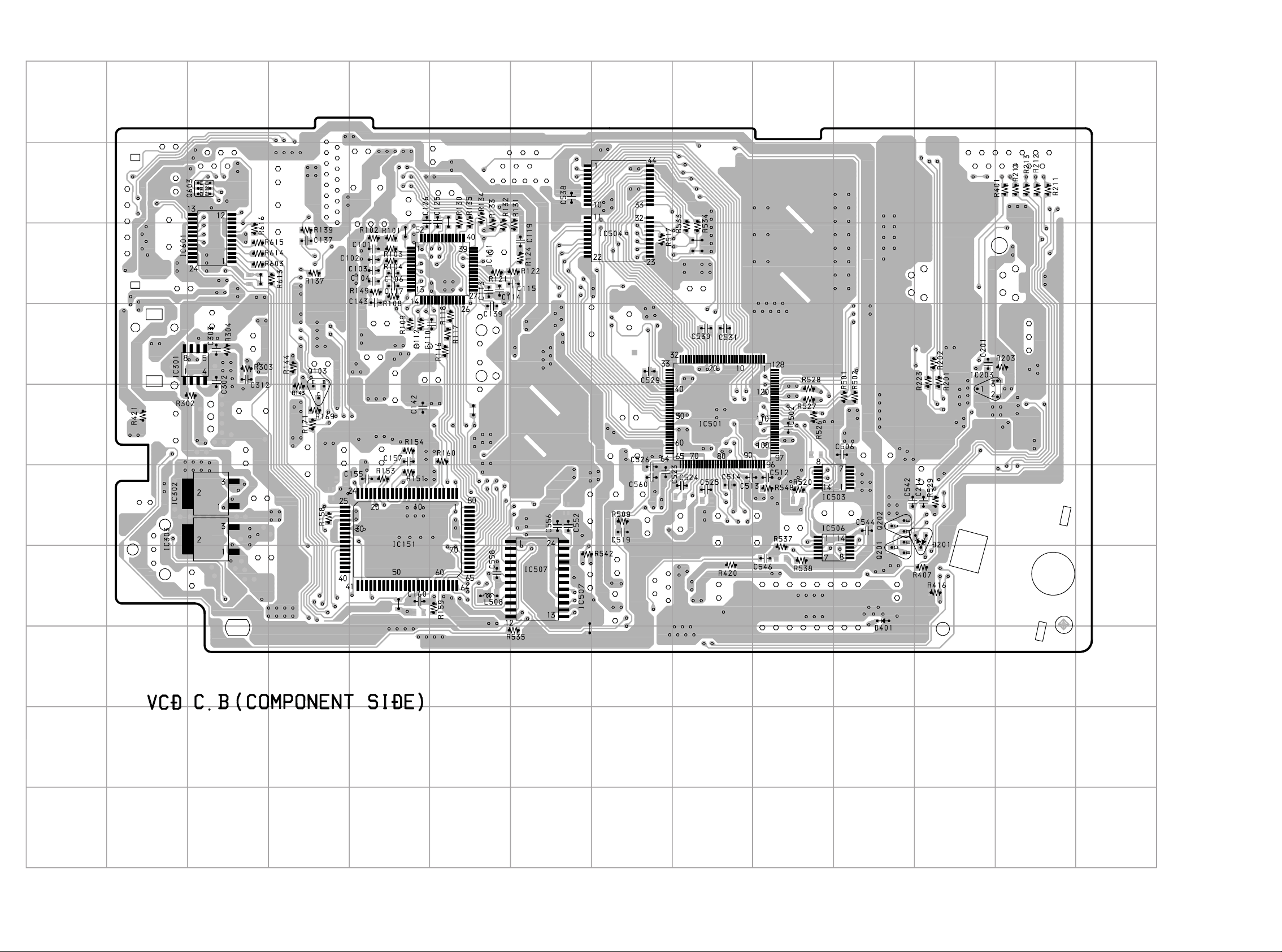
WIRING-2 (VOS1RMDSM, VOS1RMDS)
14
13 12 11 10 9 8
7
6
5
432
1
A
B
C
D
E
F
G
H
I
J
1413
Page 2
1
234567
8
9
10
11 12 13
14
A
B
C
D
E
F
G
H
I
J
1615
Page 3
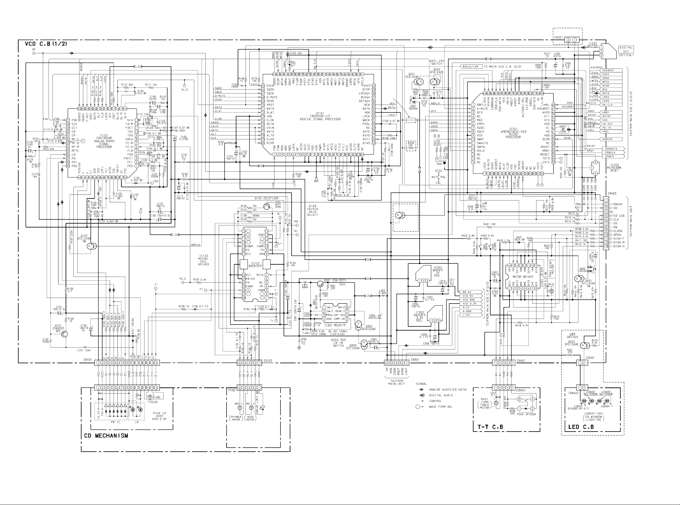
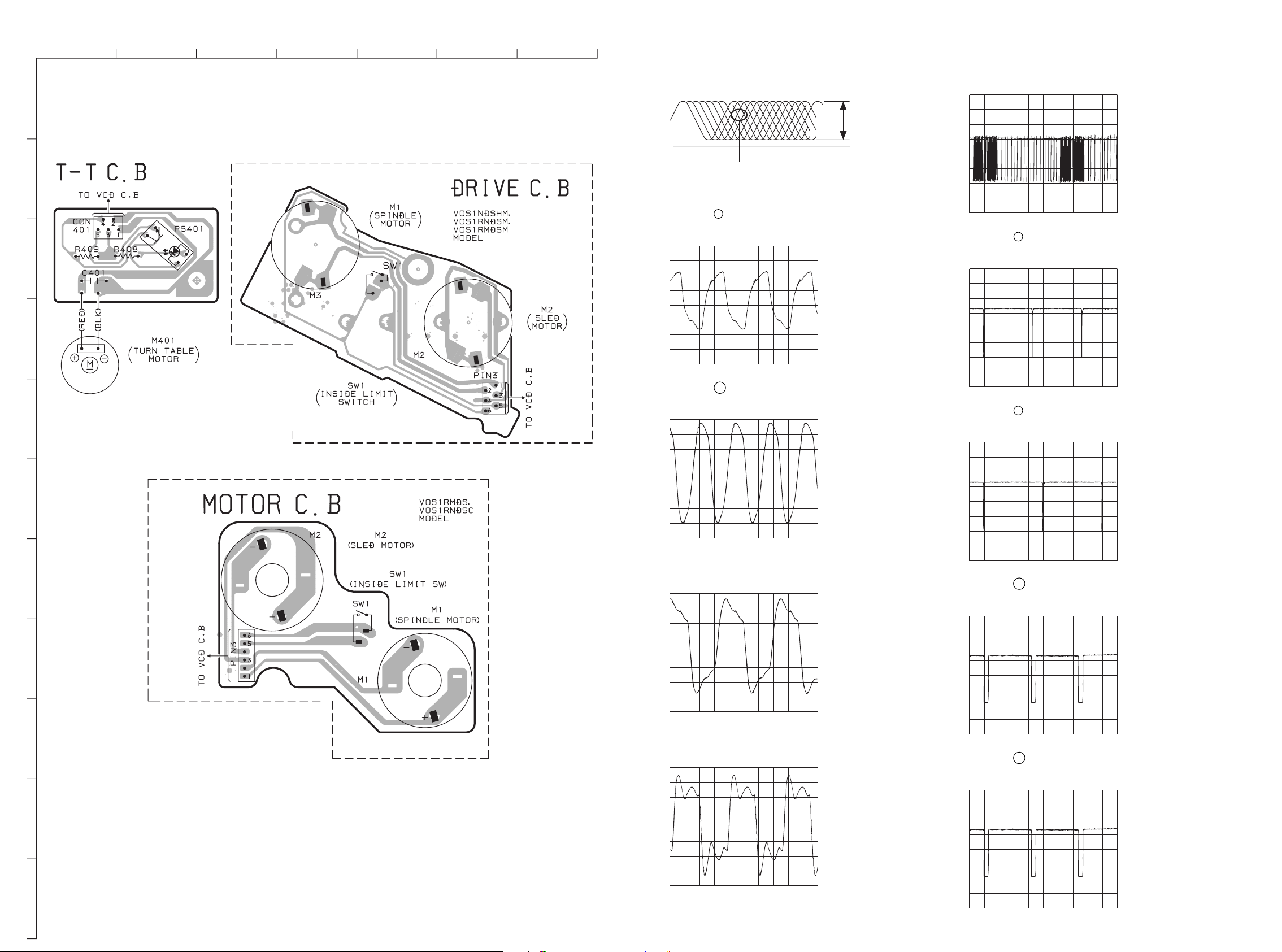
SCHEMATIC DIAGRAM-1
VOS1NDSHM,
VOS1RNDSHM,
VOS1RNDSC
MODEL
VOS1RMDSM,
VOS1RMDS
MODEL
VOS1RMDSM,
VOS1RMDS MODEL
TO
MAIN UNIT
Q203
DTC114YKA
DIGITAL
OUT
SWITCH
VOS1RMDSM,
VOS1RMDS
MODEL
VOS1NDSHM, VOS1RNDSM, VOS1RMDSM : 3ZG-2 E3
VOS1RMDS,VOS1RNDSC : KSM-2131FAM
DRIVE C.B
(VOS1NDSHM, VOS1RNDSM,
VOS1RMDSM)
MOTOR C.B
(VOS1RMDS, VOS1RNDSC)
SLP6130C-81H-S
VOS1RMDSM,
VOS1RMDS
MODEL
1817
Page 4
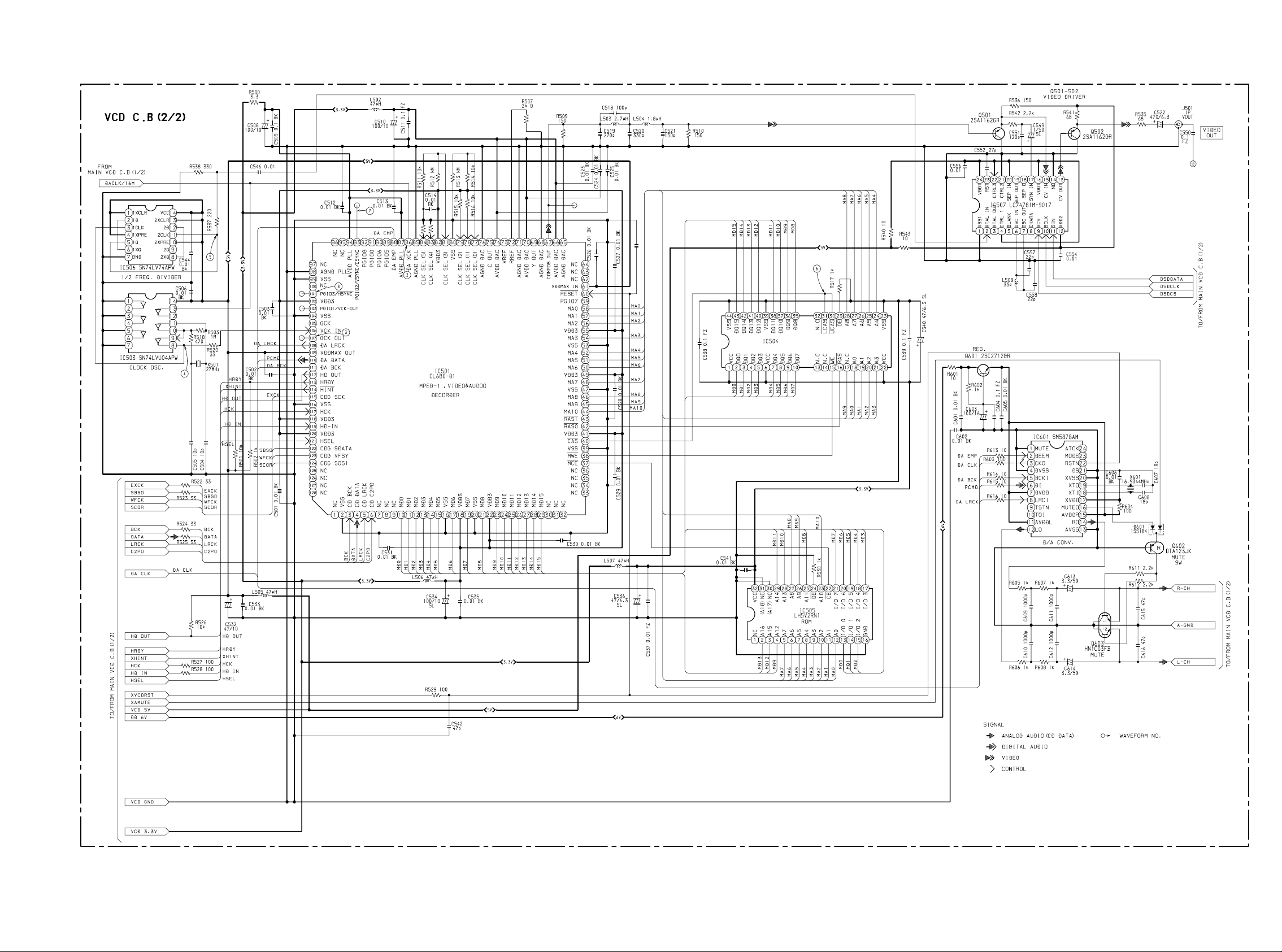
SCHEMATIC DIAGRAM-2
C560
0.01
BK
MSM54V16258 B/BS D RAM
2019
Page 5
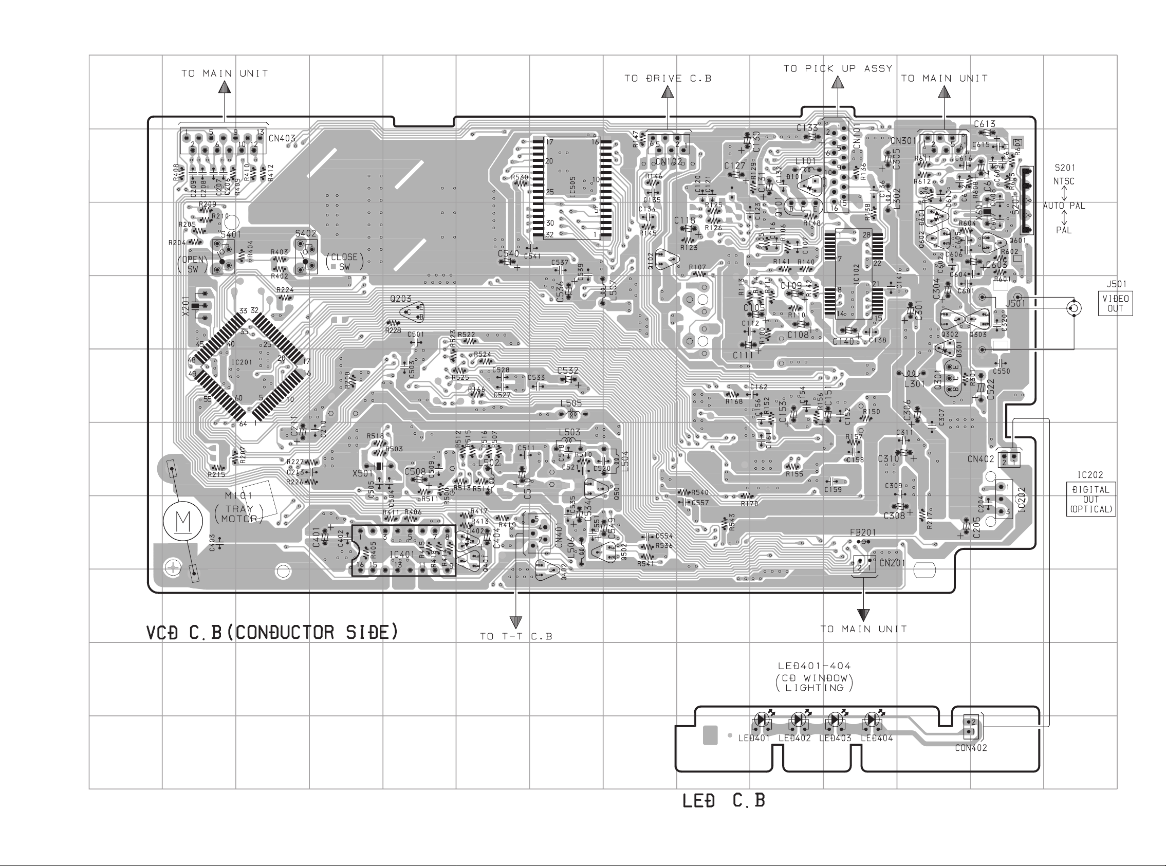
WIRING-3 (MECHA)
1
A
234567
WAVE FORM
1 IC101 Pin ‹ (RF-O) VOLT/DIV: 200mV
TIME/DIV: 0.5µS
MAX
1.2±0.1Vp-p
0V
6
IC504 Pin º UCAS VOLT/DIV: 1V
(Pin ⁄ LCAS) TIME/DIV: 2µS
___________
___________
B
2 IC501 Pin DA XCK VOLT/DIV: 1V
16.93MHz TIME/DIV: 20nS
C
D
3 IC501 Pin GCK OUT VOLT/DIV: 1V
42.3MHz TIME/DIV: 10nS
E
EYE PATTERN
must be CLEAR and MAX
86
107
____________
7
IC501 Pin VSync VOLT/DIV: 1V
NTSC TIME/DIV: 5mS
IC501 Pin VSync VOLT/DIV: 1V
PAL TIME/DIV: 5mS
93
____________
93
F
4 IC503 Pin 8 VCK VOLT/DIV: 1V
G
H
I
J
27MHz±1.35kHz TIME/DIV: 10nS
5 IC506 Pin ! OSD CLK VOLT/DIV: 1V
13.5MHz±675Hz TIME/DIV: 20nS
8
IC501 Pin HSync VOLT/DIV: 1V
PAL TIME/DIV: 20µS
IC501 Pin HSync VOLT/DIV: 1V
NTSC TIME/DIV: 20µS
101
101
____________
____________
K
21
22
Page 6
IC DESCRIPTION
IC, CXA1992AR
Pin No. Pin Name I/O Description
1
2
3
FEO
FEI
FDFCT
Output terminal for focus error amplifier. Internally connected to window comparator
O
input for bias condition.
Input terminal for focus error.
I
Capacitor connection terminal for time constant used when there is defect.
I
10
11
12
13
14
15
16
4
5
6
7
8
9
FGD
FLB
FE_O
FEM
SRCH
TGU
TG2
FSET
TA_M
TA_O
SL_P
SL_M
SL_O
This pin is connected to GND via capacitor when high frequency gain of the focus
I
servo is attenuated.
This is a pin where the time constant is externally connected to raise the low frequency
I
gain of the focus servo.
Focus drive output.
O
Focus amplifier inverted input pin.
I
This is a pin where the time constant is externally connected to generate the focus
I
search waveform.
This is a pin where the selection time constant is externally connected to set the
I
tracking servo the high frequency gain.
This is a pin where the selection time constant is externally connected to set the
I
tracking high frequency gain.
Pin for setting peak of the phase compensator of the focus tracking.
I
Tracking amplifier inverted input pin.
I
Tracking drive output.
O
Sled amplifier non-inverted input pin.
I
Sled amplifier inverted input pin.
I
Sled drive output.
O
17
18
19
20
21
22
23
24
25
26
27
28
29
30
31
ISET
Vcc
LOCK
CLK
XLT
DATA
XRST
C_OUT
SENS1
SENS2
FOK
CC2
CC1
CB
CP
The current which determines height of the focus search, track jump and sled kick is
I
input with external resistance connected.
Power supply.
I
“L” setting starts sled disorder-prevention circuit. (Not pull-up resistance)
I
Clock input for serial data transfer from CPU. (No pull-up resistance)
I
Latch input from CPU. (No pull-up resistance)
I
Serial data input from CPU. (No pull-up resistance)
I
Reset system at “L” setting. (No pull-up resistance)
I
Signal output for track number counting.
O
FZC, DFCT1, TZC, BALH, TGH, FOH, or ATSC is output depending on the
O
command from CPU.
DFCT2, MIRR, BALL, TGL or FOL is output depending on the command from CPU.
O
Output terminal for focus OK comparator.
O
Input pin where the DEFECT bottom hold output is capacitance coupled.
I
DEFECT bottom-hold output terminal. Internally connected to interruption comparator
O
input.
Connection terminal for DEFECT bottom-hold capacitor.
I
Connection terminal for MIRR hold-capacitor.
I
Anti-reverse input terminal for MIRR comparator.
23
Page 7
Pin No. Pin Name I/O Description
32
33
34
RF_I
RF_O
RF_M
I
Input terminal by capacity combination of RF summing amplifier.
O
Output terminal of RF summing amplifier. Checkpoint of Eye pattern.
Anti-reverse input terminal for RF summing amplifier.
The gain of RF amplifier is decided by the connection resistance between RF_M and
I
RFO terminals.
35
36
37
38, 39
40
41, 42
43
44
45
46
47
48
49
50
RFTC
LD
PD
PD1, PD2
FEBIAS
F, E
EI
VEE
TEO
LPFI
TEI
ATSC
TZC
TDFCT
O
I/O
—
—
O
This is a pin where the selection time constant is externally connected to control the
I
RF level.
APC amplifier output terminal.
I
APC amplifier input terminal.
RFI-V amplifier inverted input pin.
I
These pins are connected to the A+C and B+C pins of the optical pickup, receiving by
currents input.
Bias adjustment pin of the focus error amplifier.
F and EIV amplifier inverted input pins.
I
These pins are connected to the F and E of the optical pickup, receiving by current
input.
Gain adjustment pin of the I-V amplifier E. (When not in use of BAL automatic
adjustment)
GND connection pin.
Output terminal for tacking-error amplifier. Output E-F signal.
I
BAL adjustment comparator input pin. (Input through LPF from TEO)
I
Input terminal for tracking error.
I
Window-comparator input terminal for detecting ATSC.
I
Input terminal for tracking-zero cross comparator.
I
Capacitor connection pin for the time constant used when there is defect.
51
52
VC
FZC
O
Output terminal for DC voltage reduced to half of VCC+VEE.
I
Input terminal for focus-zero cross comparator.
24
Page 8
IC, CXD2540Q
Pin No. Pin Name I/O Description
1
2
3
FOK
FSW
MON
I
Focus OK input. Used for SENS output and the servo auto sequencer.
O
Spindle motor output filter switching output.
O
Spindle motor on/off control output.
10
11
12
13
14
15
16
17
18
19
20
21
22
4
5
6
7
8
9
MDP
MDS
LOCK
NC
VCOO
VCOI
TEST
PDO
VSS
PWMI
V16M
VCTL
VPCO
VCKI
FILO
FILI
PCO
AVSS
CLTV
O
Spindle motor servo control.
O
High, when sampled value of GFS at 460Hz is high.
O
Low, when sampled value of GFS at 460Hz is low by 8 times successively.
—
Not used.
O
Analog EFM PLL oscillation circuit output.
I
Analog EFM PLL oscillation circuit input. fLOCK=8.6436MHz.
I
TEST pin.
O
Analog EFM PLL charge pump output.
—
GND.
I
Spindle motor external control input.
O
VCO2 oscillation output for the wide-band EFM PLL.
I
VCO2 control voltage input for the wide-band EFM PLL.
O
Wide-band EFM PLL charge pump output.
I
VCO2 oscillation input for the wide-band EFM PLL.
O
Multiplier PLL (slave=digital PLL) filter output.
I
Multiplier PLL filter input.
O
Multiplier PLL charge pump output.
—
Analog GND.
I
Multiplier VCO1 control voltage input.
23
24
25
26
27
28
29
30
31
32
33
34
35
36
37
38
AVDD
RF
BIAS
ASYI
ASYO
ASYE
NC
PSSL
WDCK
LRCK
VDD
DA16
DA15
DA14
DA13
DA12
—
Analog power supply (5V).
I
EFM signal input.
I
Constant current input of the asymmetry circuit.
I
Asymmetry comparator voltage input.
O
EFM full-swing output.
I
Low: asymmetry circuit off; high: asymmetry circuit on.
—
Not used.
I
Audio data output mode switching input. Low: serial output; high: parallel output.
O
D/A interface for 48-bit slot. Word clock f=2Fs.
O
D/A interface for 48-bit slot. LR clock f=Fs.
—
Power supply (5V).
DA16 (MSB) output when PSSL=1.
O
48-bit slot serial data (two’s complement, MSB first) when PSSL=0.
O
DA15 output when PSSL=1. 48-bit slot bit clock when PSSL=0.
DA14 output when PSSL=1.
O
64-bit slot serial data (two’s complement, LSB first) when PSSL=0.
O
DA13 output when PSSL=1. 64-bit slot bit clock when PSSL=0.
O
DA12 output when PSSL=1. 64-bit slot LR clock when PSSL=0.
25
Page 9

Pin No. Pin Name I/O Description
39
40
41
DA11
DA10
DA09
O
DA11 output when PSSL=1. GTOP output when PSSL=0.
O
DA10 output when PSSL=1. XUGF output when PSSL=0.
O
DA09 output when PSSL=1. XPLCK output when PSSL=0.
42
43
44
45
46
47
48
49
50
51
52
53
54
55
56
57
58
59
60
DA08
DA07
DA06
DA05
DA04
DA03
DA02
DA01
APTR
APTL
VSS
XTAI
XTAO
XTSL
FSTT
FSOF
C16M
MD2
DOUT
—
O
DA08 output when PSSL=1. GFS output when PSSL=0.
O
DA07 output when PSSL=1. RFCK output when PSSL=0.
O
DA06 output when PSSL=1. C2PO output when PSSL=0.
O
DA05 output when PSSL=1. XRAOF output when PSSL=0.
O
DA04 output when PSSL=1. MNT3 output when PSSL=0.
O
DA03 output when PSSL=1. MNT2 output when PSSL=0.
O
DA02 output when PSSL=1. MNT1 output when PSSL=0.
O
DA01 output when PSSL=1. MNT0 output when PSSL=0.
Aperture compensation control output.
O
This pin outputs a high signal when the right channel is used.
Aperture compensation control output.
O
This pin outputs a high signal when the left channel is used.
GND.
I
Crystal oscillation circuit input.
O
Crystal oscillation circuit output.
I
Crystal selector input.
O
2/3 frequency divider output for Pins 53 and 54.
O
1/4 frequency divider output for Pins 53 and 54.
O
16.9344MHz output. (V16M output in CLV-W and CAV-W modes)
I
Digital-out on/off control. High: on; low: off
O
Digital-out output.
61
62
63
64
65
66
67
68
69
70
71
72
73
74
75
76
EMPH
WFCK
SCOR
SBSO
EXCK
SQSO
SQCK
MUTE
SENS
XRST
DATA
XLAT
VDD
CLOK
SEIN
CNIN
—
Outputs a high signal when the playback disc has emphasis, and a low signal when
O
there is no emphasis.
I
WFCK (write frame clock) output.
O
Outputs a high signal when either subcode sync S0 or S1 is detected.
O
Sub P to W serial output.
I
SBSO readout clock input.
O
Sub Q 80-bit and PCM peak, level metter and internal status outputs.
I
SQSO readout clock input.
I
High: mute; low: release
SENS output to CPU.
I
System reset. Reset when low.
O
Serial data input from CPU.
O
Latch input from CPU. Serial data is latched at the falling edge.
Power supply (5V).
O
Serial data transfer clock input from CPU.
I
SENS input from SSP.
I
Track jump count signal input.
26
Page 10

Pin No. Pin Name I/O Description
77
78
79
DATO
XLTO
CLKO
Serial data output to SSP.
O
Serial data latch output to SSP. Latched at the falling edge.
O
Serial data transfer clock output to SSP.
O
80
Notes)
• The 64-bit slot is an LSB first, two’s complement output, and the 48-bit slot is an MSB first, two’s complement output.
• GTOP is used to monitor the frame sync protection status. (High: sync protection window open.)
• XUGF is the negative pulse for the frame sync obtained from the EFM signal. It is the signal before sync protection.
• XPLCK is the inverse of the EFM PLL clock. The PLL is designed so that the falling edge and the EFM signal transition point
coincide.
• GFS goes high when the frame sync and the insertion protection timing match.
• RFCK is derived from the crystal accuracy, and has a cycle of 136µ.
• C2PO represents the data error status.
• XRAOF is generated when the 32K RAM exceeds the ±28F jitter margin.
MIRR
Mirror signal input. Used when the number of tracks is 128 or more for the 2N-track
I
jump and M track move of the auto sequencer.
27
Page 11

IC, CL680
Pin No. Pin Name I/O Description
1
2
3
NC
VSS
CD BCK
—
—
No connection.
GND.
I
Bit clock input from CD DSP.
4
5
6
7-9
10-15
16
17
18
19
20
21
22
23-29
30-36
37
38
39
40
41
42
43
44-46
47
48
CD DATA
CD LRCK
CD C2PO
NC
MD0-MD5
VSS
MD6
VDD3
MD7
VSS
MD8
VDD3
MD9-MD15
NC
________
MCE
__________
MWE
VSS
________
CAS
VDD3
___________
RASO
___________
RASI
MA10-MA8
VSS
MA7
—
I/O
—
I/O
—
I/O
—
I/O
—
I/O
—
—
O
—
O
—
O
O
O
—
O
I
Data input from CD DSP.
I
LRCK input from CD DSP.
I
C2 pointer input from CD DSP.
No connection.
DRAM/ROM interface. (DATA)
Ground.
DRAM/ROM interface. (DATA)
Power supply 3.3V.
DRAM/ROM interface. (DATA)
Ground.
DRAM/ROM interface. (DATA)
Power supply 3.3V.
DRAM/ROM interface. (DATA)
No connection.
ROM chip enable.
DRAM write enable.
Ground.
DRAM/ROM interface.
Power supply 3.3V.
DRAM/ROM interface.
DRAM/ROM interface. (Address)
Ground.
DRAM/ROM interface. (Address)
49
50-52
53
54
55
56-58
59
60
61
62-64
65
66
67
68
VDD3
MA6-MA4
VSS
MA3
VDD3
MA2-MA0
PGIO7
______________
RESET
VDD MAX IN
NC
AGND DAC
A DAC
COMP OUT
AGND DAC
—
O
—
O
—
O
I/O
—
—
—
—
O
—
Power supply 3.3V.
DRAM/ROM interface. (Address)
Ground.
DRAM/ROM interface. (Address)
Power supply 3.3V.
DRAM/ROM interface. (Address)
Programmable I/O.
I
Reset input.
Power supply - VDDMAX. (5.0V)
No connection.
Analog ground.
Analog power supply (DAC) : 3.3V.
Composite out.
Analog ground.
28
Page 12

Pin No. Pin Name I/O Description
Video signal “Y” OUT.
69
70
71
72
73
74
75
76
77-79
80
81
82
83, 84
85
86
87
88
89, 90
Y OUT
AVDD DAC
AGND DAC
R REF
V REF
AVDD DAC
C OUT
AGND DAC
CLK SEL0-2
VSS
CLK SEL3
VDD3
CLK SEL4, 5
AGND PLL
DA XCK
AVDD PLL
DA EMP
PGIO5, O6
O
—
—
—
O
—
—
—
—
—
O
I/O
Analog power supply (DAC) 3.3V.
Analog ground.
Reference resistor input.
I
Voltage reference input.
I
Analog power supply (DAC) : 3.3V.
Video signal “C” out.
Analog ground.
Clock selection input.
I
Ground.
Clock selection input.
I
Power supply 3.3V.
Clock selection input.
I
Analog ground.
DA XCK (16.933MHz) input.
I
Analog power supply 3.3V.
DAC-emphasis output.
91
92
93
94
95
96
97
98
99
100
101
102
103
104
105
106
107
108
109
PGIO0
PGIO8
______________ ______________
VSYNC/CSYNC
AVDD PLL
VID_DAC_CK
PROC_CK
AUD_XCK
AGND PLL
VSS
NC
______________
HSYNC
VDD3
VCK OUT
VSS
GCK
VCK
GCK OUT
DA LRCK
VDD MAX OUT
I/O
I/O
O
—
O
O
O
—
—
—
O
—
O
—
O
O
—
Programmable I/O.
______________ ______________
VSYNC/CSYNC output.
Analog power supply (PLL) 3.3V.
Video DAC clock.
Processor clock.
Audio XCK.
Analog ground.
Ground.
No connection.
______________
HSYNC output.
Power supply 3.3V.
VCK out.
Ground.
Global clock signal input. (42.3MHz)
I
Video clock signal input. (27.0MHz)
I
Global clock signal output. (27.0MHz)
DAC-LRCK output.
Power supply (VDD MAX) : 5.0V.
110
111
112
113
DA DATA
DA BCK
HD OUT
HRDY
DAC-PCM data output.
O
DAC-BIT clock output.
O
Micon interface. (Data out)
O
Micon interface. (Host ready)
O
29
Page 13

Pin No. Pin Name I/O Description
__________
114
115
HINT
CDG SCK
Micon interface. (Host interrupt)
O
CD-G serial clock input.
I
116
117
118
119
120
121
122
123
124
125
126-128
VSS
HCK
VDD3
HD IN
VDD3
HSEL
CDG DATA
CDG VFSY
CDG SOSI
DSP-XCK
NC
—
—
—
—
Ground.
Micon interface. (Host clock)
I
Power supply 3.3V.
Micon interface. (Host data in)
I
Power supply 3.3V.
Micon interface. (Host select in)
I
CD-G data input.
I
CD-G VFSY input.
I
CD-G SOSI input.
I
DSP-XCK output.
O
No connection.
30
Page 14

IC, LC74781M
Pin No. Pin Name I/O Description
1
2
3
VSS1
Xtal IN
Xtal OUT
GND connection terminal. (Digital ground terminal).
—
I
External X’tal and capacitor for internal sync generator, or the external clock are
connected to this terminal. (2fsc or 4fsc).
O
10
11
12
4
CTRL1
Either the external clock input mode or the X’tal generator mode is selected by this
I
selector terminal. L: X’tal generator mode, H: External clock input.
Blank signal (character and the green ORed signal) is output from this terminal.
5
BLANK
(MODE 0: composite sync signal is output at H.) When reset (RST terminal = L), the
O
________
X’tal clock signal is output. (It is not output when reset by the reset command).
6
7
OSC IN
OSC OUT
I
External coil and capacitor for the character output dot clock generator are connected
to this terminal.
O
The character signal is output from this terminal. (MOD 0: when H, the external sync
signal identification signal is output from this terminal. This output signal tells whether
8
CHARA
the external sync signal is present or not. When external sync signal is present, H is
O
________
output.) When reset (RST terminal = L), the dot clock signal (LC oscillator) is output.
(It is not output when reset by the reset command).
______
9
CS
Enable signal for the serial data input is input to this terminal. The serial data input is
I
enabled at L. Pull-up resistor is built-in. (Hysteresis input).
SCLK
Clock of the serial data input is input to this terminal. Pull-up resistor is built-in.
I
(Hysteresis input).
SIN
VDD2
Serial data input terminal. Pull-up resistor is built-in. (Hysteresis input).
I
Power supply for the composite video signal level adjustment. (Analog power supply).
—
13
14
15
16
17
18
19
20
21
CV OUT
NC
CV IN
VDD1
SYN IN
SEP C
SEP OUT
SEP IN
CTRL2
Composite video signal output terminal.
O
Connected to GND or not connected.
—
Composite video signal input terminal.
I
Power supply (+5V digital power supply).
—
Video signal for the internal sync separator circuit is input to this terminal. (When the
internal sync separator circuit is not used, the horizontal sync signal or composite sync
I
signal is input to this terminal).
Internal sync separator circuit bias voltage monitoring terminal.
—
The composite sync output signal of the internal sync separator circuit is output from
this terminal. (H: MOD 1. H: during internal sync mode. L: during external sync
O
mode.) (When internal sync separator circuit is not used, the SYN IN input signal is
output from this terminal).
The output signal of the SEP OUT terminal is integrated so that the vertical sync signal
is input to this terminal. An integrator circuit must be connected between the SEP
I
OUT terminal and this terminal. When this terminal is not used, it must be connected
to VDD1.
When selecting any of the NTSC or PAL or PAL-M or PAL-N system, the pin setting
has priority. When L, the NTSC system is selected after resetting. Selection of either
I
NTSC or PAL or PAL-M or PAL-N system by the command becomes effective. H:
PAL-M system.
31
Page 15

Pin No. Pin Name I/O Description
______________
22
CTRL3
Controls whether or not to input the VSYNC signal to the SEPIN input. L: to input the
I
______________ ______________
VSYNC signal. H: not to input the VSYNC signal.
23
________
RST
I
System reset input terminal. Pull-up resistor is built-in. (Hysteresis input).
24
VDD1
—
Power supply. (+5V digital power supply).
32
Page 16

IC, µPD78016FGC
Pin No. Pin Name I/O Description
1
2
3
RBPLS
AMUTE
GFS
RADIAL BALANCE PLUS.
O
AUDIO ANALOG MUTE (H=MUTE ON).
O
GFS.
I
10
11
12
13
14
15
16
17
18
19
20
21
22
4
5
6
7
8
9
XVCDMD
MD2
EMPH
SQSO
SQCK
VSS
SWNT
SWAUTO
SWPAL
EMERG
NC
LPCSEL
NC
LOCK
DMUTE
SENS
XCDRST
DATA
XLAT
AUDIO/VIDEO CD MODE (L=VCD=SPINDLE GAIN UP).
I
DOUT MUTE CONT.
O
EMPHASIS.
I
SQDATA FROM CD.
I
SQCLK TO CD.
O
GND.
—
SW TV OUT MODE (L=NTSC).
I
SW TV OUT MODE (L=NTSC/PAL AUTO).
I
SW TV OUT MODE (L=PAL).
I
POWER EMERGENCY STOP (L*3sec=STOP).
I
Nou used.
—
“LPC ON/OFF (H=ON, NORMAL)”.
I
Nou used.
—
GFS (FRAME SYNC) LOCK (NO USE=H).
O
DIGITAL DATA OUT MUTE.
O
DSP SENS1 FROM CD.
I
CD RESET.
O
DATA TO CD.
O
XLT TO CD.
O
23
24
25
26
27
28
29
30
31
32
33
34
35
36
37
38
39
40
CLOK
VSS
FOK
SENS2
XBUSY
NC
NC
NC
TST0
TST1
TST2
TST3
RESET
HRDY
XHINT
NC
SCOR
VDD
O
—
I/O
—
—
—
I/O
I/O
I/O
I/O
—
—
CLK TO CD.
GND.
FOCUS OK.
I
SSP SENS2 FROM CD.
I
READY/BUSY I/O TO HOST OD.
Nou used.
CHECK LAND.
RESET.
I
HRDY FROM CL680.
I
HINT FROM CL680.
I
Nou used.
SCOR FROM CD.
I
5.0VDD.
41
XO
8.0MHz CERALOCK.
O
33
Page 17

Pin No. Pin Name I/O Description
42
43
44
XI
VSS
XT2
—
—
8.0MHz CERALOCK.
I
GND.
Nou used.
45
46
47
48
49
50
51
52
53
54
55
56
57
58
59
60
61
62
63
XT1
AVSS
XMPGRST
HSEL
INLSW
NC
OSDXCS
ABSEL
CLVSEL
AADSEL
AVDD
AVREF
HDOUT
HDIN
HCK
OSDDATA
OSDCLK
COMMAND
STATUS
—
—
—
—
5.0VDD.
I
GND.
MPEG BLOCK IC RESET.
O
ADDRESS/DATA SEL TO CL680.
O
INSIDE LIMIT SW.
I
Nou used.
OSD CHIP SELECT.
O
CXA1992A/B SELECT (L=CXA1992A).
I
CLV MODE SELECT (H=CLV-N).
I
AUTO ADJUST SELECT (H=AUTO ON).
I
5.0VDD.
HD-OUT FROM CL680.
I
HD-IN TO CL680.
O
HCK TO CL680.
O
OSD DATA.
O
OSD CLOCK.
O
COMMAND FROM HOST.
I
STATUS TO HOST.
O
64
SCK
SCK FROM HOST.
I
34
Page 18

IC, SM5878M
Pin No. Pin Name I/O Description
1
2
3
MUTE
DEEM
CKO
MODE = H: Soft mute ON/OFF terminal. (Mute at H).
I
MODE = L: Attenuator level DOWN/UP terminal. (DOWN at H).
I
De-emphasis ON/OFF terminal. (De-emphasis ON at H).
O
Oscillator clock output. (16.9344 MHz).
10
11
12
13
14
15
16
17
18
19
20
21
22
4
5
6
7
8
9
DVSS
BCKI
DI
DVDD
LRCI
TSTN
TO1
AVDDL
LO
AVSS
RO
AVDDR
MUTEO
XVDD
XTI
XTO
XVSS
DS
RSTN
—
Digital VSS terminal.
I
Bit clock input terminal.
I
Serial data input terminal.
—
Digital VDD terminal.
I
Sample rate clock (fs) input terminal. (H = L ch/L = R ch).
I
Test input. (“H” or open during normal operation)
O
Test output 1. (Normally low level output).
—
Analog VDD terminal. (For L ch).
O
Left channel analog output terminal.
—
Analog VSS terminal.
O
Right channel analog output terminal.
—
Analog VDD terminal. (For R ch).
O
Infinity zero detection output.
—
X’tal system VDD terminal.
I
X’tal oscillator terminal. (Or external clock input terminal of 16.9344 MHz).
O
X’tal oscillator terminal.
—
X’tal system VSS terminal.
I
Double-speed/normal playback selection. (Double-speed at H).
I
Reset terminal. (Reset at L).
23
24
MODE
ATCK
I
Soft mute/Attenuator mode selection. (Soft mute at H).
I
Attenuator level setup clock (Ignored when MODE = H).
35
Page 19

IC BLOCK DIAGRAM
IC, BA5915FP
IC, M5291FP
6.65K
6.65K
CH1
MUTE
6.65K
6.65K
T.S.D: Thermal shut-down
Resistors are in units of Ω.
Switch collector Driver
Switch emitter
OSC
Peak currect
detection
IC, LB1644
External capacitance
for oscillation
Ground
1.17V
REF. VOL
Power supply
Comparator input
36
Page 20

TEST MODE
1. How to Activate CD Test Mode
Insert the AC plug while pressing the function CD button.
All FL display tubes will light up, and the test mode will be
activated.
3. CD Test Mode Functions
When test mode is activated, the following mode functions from No.1 to No.5 can be used by pressing the operation keys.
2. How to Cancel CD Test Mode
Either one of the following operations will cancel the CD test
mode.
• Press the function button. • Press the power switch button.
(except CD function button) • Disconnect the AC plug
Mode/No.
Start mode
No.1
Search mode
No.2
Play mode
No.3
Traverse mode
Operation
Activation
9 key
1 2 key
key
;
FL display
TEST 00 00 00
Flashes repeatdly
Operation
• Test mode is activated.
• CD block power is ON.
• Continual focus search
(The pickup lens repeats the fullswing up-down motion.)
* Avoid continual searches that last for
more than 10 minutes. * NOTE 1
• Normal playback
• Focus search is continued if TOC
cannot be read. * NOTE 1
• During normal disc playback
Press once; tracking servo OFF
Contents
• Test mode
FOCUS SERVO
• Check focus search waveform
• Check focus error waveform
(FOK/FZC are not monitored in the
search mode)
FOCUS SERVO/TRACKING SERVO
CLV SERVO/SLED SERVO
Check FOK/FZC
TRACKING SERVO ON/OFF
Tracking balance (traverse) check
Press twice; tracking servo ON
No.4
Sled mode
fi key
fl
All lamps light
• Pickup moves to the outermost track
• Pickup moves to the innermost track
* NOTE 2
SLED SERVO
Check SLED mechanism operation
* NOTE 3
(During playback, machine operates
No.5
normally.)
* NOTE 1: There are cases when the tracking servo cannot be locked owing to the protection circuit being operated when heat builds up
in the driver IC if the focus search is operated continually for more than 10 minutes. In these cases the power supply should be
switched off for 10 minutes until heat has been reduced and then re-started.
* NOTE 2: Do not press the fi or fl keys when the machine is in the
after the
status has been canceled. If the fi or fl keys are pressed in the ; status, press the 9 key and return to the start mode
;
status is active. If they are pressed, playback will not be possible
;
(No.1).
* NOTE 3: When pressing the fi or fl keys, take care to avoid damage to the gears. Because the sled motor is activated when the fi or fl
keys are pressed, even when the pick-up is at the outermost or innermost track.
4. Operation Outline
The operation of each mode is carried out in the direction of the arrows from the start mode as indicated in the following illustration.
No. 3
Play modeSearch mode
;
No. 4
Traverse mode
2
No. 2
No. 5
9
Sled mode
1 2
9
No. 1
Start mode
(All FLs light up.)
fi
fl
;
9
1 2
;
9
If the DISC DIRECT PLAY button is pressed, the machine performs the same operation as the PLAY button is pressed as shown. If
the tray is opened by pressing OPEN/CLOSE button during Play mode or Traverse mode, the machine returns to the Start mode.
5. How to check the Automatic Adjustment Values
The automatic adjustment values can be checked by pressing the square (9) button.
FL display (displayed in hexadecimal values)
** ** **
Tracking balance (00-0F)
Tracking gain (00-0C)
Focus bias (10-2F) Note) The reference value is “20 08 08”.
37
Page 21

MECHANICAL EXPLODED VIEW 1/1
11
22
24
15
17
A
A
12
3
21
20
B
18
4
26
7
P.C.B
19
14
B
B
8
30
C
1
13
28
A
16
23
A
9
6
2
P.C.B
27
10
2
29
25
P.C.B
3ZG-2 E3
KSM-2131 FAM
CUSH CD A
38
5
5
Page 22

MECHANICAL PARTS LIST 1/1
REF. NO PART NO. KANRI DESCRIPTION
NO.
1 84-ZG1-239-210 PULLY,WORM N<EXCEPT VOS1RNDSC>
1 84-ZG1-273-010 PULLEY,WORM 4<VOS1RNDSC>
2 84-ZG1-267-010 PULLEY,LOAD MO 8
3 81-ZG1-239-010 S-SCREW,TT
4 81-ZG1-291-110 GEAR,TRAY RELAY NO3
5 81-ZG1-271-010 S-SCREW MECH REAR
6 84-ZG1-289-010 HLDR,MAGNET NAT
<VOS1NDSHM,VOS1RNDSM>
6 81-ZG1-277-310 HLDR,MAGNET N<VOS1RMDSM,VOS1RMDS>
6 84-ZG1-291-010 HLDR,MAGNET 4 NAT<VOS1RNDSC>
7 81-ZG1-255-110 PLATE,MAGNET MK2
8 83-ZG3-213-010 LVR,SW
9 84-ZG1-003-310 TRAY,NO2-B<VOS1NDSHM>
9 84-ZG1-008-210 TRAY,NO3<EXCEPT VOS1NDSHM>
10 87-045-364-010 MOTOR(BCH3B14)
11 84-ZG1-005-210 TURNTABLE,NO1(*)
12 84-ZG1-011-010 REFLECTOR,CD
13 84-ZG1-259-010 SPR-P,WORM
14 84-ZG1-266-010 LEVER,CAM 8<EXCEPT VOS1RNDSC>
14 84-ZG1-208-210 LEVER,CAM<VOS1RNDSC>
15 84-ZG1-209-010 BELT,SQ1.8-117.7
16 84-ZG1-211-010 SPR-E CAM S
17 84-ZG1-215-410 GEAR,MAIN CAM BLU
<VOS1RMDSM,VOS1RMDS>
17 84-ZG1-203-410 GEAR,MAIN CAM
<EXCEPT VOS1RMDSM,VOS1RMDS>
18 84-ZG1-216-310 SLIDE,MECHA CAM YEL
<VOS1RMDSM,VOS1RMDS>
18 84-ZG1-204-310 SLIDER,MECHA CAM
<EXCEPT VOS1RMDSM,VOS1RMDS>
REF. NO PART NO. KANRI DESCRIPTION
19 84-ZG1-205-210 GEAR,TRAY (*)
20 84-ZG1-274-010 GEAR,RELAY 8<EXCEPT VOS1RNDSC>
20 84-ZG1-206-110 GEAR,RELAY<VOS1RNDSC>
21 84-ZG1-207-010 PULLEY,RELAY<EXCEPT VOS1RNDSC>
21 84-ZG1-271-010 PULLEY,RELAY 8<VOS1RNDSC>
22 84-ZG1-269-010 GEAR,MAIN TT 4
23 84-ZG1-238-010 GEAR,WORM N
24 84-ZG1-224-010 LEVER,TT<VOS1RMDSM,VOS1RMDS>
24 84-ZG1-288-010 LEVER,TT NAT
25 84-ZG1-225-010 BELT,SQ1.0-63.3
26 83-ZG3-604-010 RING,MAG 2
27 87-045-305-010 MOTOR, RF-500TB DC-5V (2MA)
27 87-045-383-010 MOT,M9I50T28-2<VOS1RNDSC>
28 84-ZG1-248-010 SPR-C,WORM
29 84-ZG1-287-010 HLDR,MECHA NAT
29 84-ZG1-212-210 HLDR,MECHA NO2
30 84-ZG1-286-010 CHAS,MECHA NAT
30 84-ZG1-201-410 CHAS,MECHA<VOS1RMDSM,VOS1RMDS>
30 84-ZG1-292-010 CHAS,MECHA N NAT<VOS1RNDSC>
A 87-067-703-010 TAPPING SCREW, BVT2+3-10
B 87-251-070-410 U+2.6-3
C 87-067-981-010 BVT2+3-6 BLK
NO.
<EXCEPT VOS1RMDSM,VOS1RMDS>
<EXCEPT VOS1RNDSC>
<EXCEPT VOS1RMDSM,VOS1RMDS>
<VOS1RMDSM,VOS1RMDS>
<VOS1NDSHM,VOS1RNDSM>
COLOR NAME TABLE
Basic color symbol Color Basic color symbol Color Basic color symbol Color
B Black C Cream D Orange
G Green H Gray L Blue
LT Transparent Blue N Gold P Pink
R Red S Silver ST Titan Silver
T Brown V Violet W White
WT Transparent White Y Yellow YT Transparent Yellow
LM Metallic Blue LL Light Blue GT Transparent Green
LD Dark Blue DT Transparent Orange
39
Page 23

CD MECHANISM EXPLODED VIEW 1/1 (3ZG-2E3)
12
8
A
A
11
2
6
A
A
1
5
P.C.B
CD MECHANISM PARTS LIST 1/1 (3ZG-2E3)
3
4
REF. NO PART NO. KANRI DESCRIPTION
NO.
1 83-ZG2-243-210 CHAS ASSY,SHT
2 83-ZG2-235-010 GEAR,A3
3 83-ZG2-205-210 GEAR,B
4 83-ZG2-236-010 GEAR MOTOR 3
5 83-ZG2-253-010 SHAFT,SLIDE 5
6 87-A90-836-010 PICKUP,KSS-213F
8 83-ZG2-227-210 TURN TABLE,C1
11 83-ZG2-245-410 LEVER,SHUTTER
12 83-ZG2-250-110 SPR-E,SHT 2
A 87-261-032-210 SCREW V+2-3
40
Page 24

CD MECHANISM EXPLODED VIEW 1/1 (KSM-2131 FAM)
11
12
6
2
COVER
8
SPINDLE MOTOR
7
CD MECHANISM PARTS LIST 1/1 (KSM-2131 FAM)
REF. NO PART NO. KANRI DESCRIPTION
NO.
1 9X-262-629-220 MOTOR CHASSIS ASSY(MB)(FR)
2 92-626-907-010 GEAR(A)(S)
6 87-A90-836-010 OPTICAL PICK UP KSS-213F
7 92-626-908-020 SHAFT SLED
8 92-627-003-010 GEAR(B)
11 92-646-697-020 LENS SHUTTER(F)
12 92-646-702-010 SPRIG EXTENSION
A 97-621-255-150 SCREW+P2-3
A
1
MOTOR C.B
41
Page 25

2–11, IKENOHATA 1–CHOME, TAITO-KU, TOKYO 110-8710, JAPAN TEL:03 (3827) 3111
931261
Printed in Singapore
 Loading...