

Page 1
Fifth Edition, last update January 1, 2004
Page 2

2
Page 3

Lessons In Electric Circuits, Volume I – DC
By Tony R. Kuphaldt
Fifth Edition, last update January 1, 2004
Page 4

c
° 1998-2003, Tony R. Kuphaldt
This book is published under the terms and conditions of the Design Science License. These
terms and conditions allow for free copying, distribution, and/or modification of this document by
the general public. The full Design Science License text is included in the last chapter.
As an open and collaboratively developed text, this book is distributed in the hope that it
will be useful, but WITHOUT ANY WARRANTY; without even the implied warranty of MERCHANTABILITY or FITNESS FOR A PARTICULAR PURPOSE. See the Design Science License
for more details.
Available in its entirety as part of the Open Book Project collection at http://www.ibiblio.org/obp
PRINTING HISTORY
• First Edition: Printed in June of 2000. Plain-ASCII illustrations for universal computer
readability.
• Second Edition: Printed in September of 2000. Illustrations reworked in standard graphic
(eps and jpeg) format. Source files translated to Texinfo format for easy online and printed
publication.
• Third Edition: Equations and tables reworked as graphic images rather than plain-ASCII text.
i
• Fourth Edition: Printed in August 2001. Source files translated to SubML format. SubML is
a simple markup language designed to easily convert to other markups like LATEX, HTML, or
DocBook using nothing but search-and-replace substitutions.
• Fifth Edition: Printed in August 2002. New sections added, and error corrections made, since
the fourth edition.
Page 5

ii
Page 6

Contents
1 BASIC CONCEPTS OF ELECTRICITY 1
1.1 Static electricity . . . . . . . . . . . . . . . . . . . . . . . . . . . . . . . . . . . . . . 1
1.2 Conductors, insulators, and electron flow . . . . . . . . . . . . . . . . . . . . . . . . . 7
1.3 Electric circuits . . . . . . . . . . . . . . . . . . . . . . . . . . . . . . . . . . . . . . . 11
1.4 Voltage and current . . . . . . . . . . . . . . . . . . . . . . . . . . . . . . . . . . . . 13
1.5 Resistance . . . . . . . . . . . . . . . . . . . . . . . . . . . . . . . . . . . . . . . . . . 22
1.6 Voltage and current in a practical circuit . . . . . . . . . . . . . . . . . . . . . . . . . 27
1.7 Conventional versus electron flow . . . . . . . . . . . . . . . . . . . . . . . . . . . . . 28
1.8 Contributors . . . . . . . . . . . . . . . . . . . . . . . . . . . . . . . . . . . . . . . . 32
2 OHM’s LAW 33
2.1 How voltage, current, and resistance relate . . . . . . . . . . . . . . . . . . . . . . . . 33
2.2 An analogy for Ohm’s Law . . . . . . . . . . . . . . . . . . . . . . . . . . . . . . . . 38
2.3 Power in electric circuits . . . . . . . . . . . . . . . . . . . . . . . . . . . . . . . . . . 39
2.4 Calculating electric power . . . . . . . . . . . . . . . . . . . . . . . . . . . . . . . . . 42
2.5 Resistors . . . . . . . . . . . . . . . . . . . . . . . . . . . . . . . . . . . . . . . . . . . 44
2.6 Nonlinear conduction . . . . . . . . . . . . . . . . . . . . . . . . . . . . . . . . . . . . 49
2.7 Circuit wiring . . . . . . . . . . . . . . . . . . . . . . . . . . . . . . . . . . . . . . . . 54
2.8 Polarity of voltage drops . . . . . . . . . . . . . . . . . . . . . . . . . . . . . . . . . . 58
2.9 Computer simulation of electric circuits . . . . . . . . . . . . . . . . . . . . . . . . . 59
2.10 Contributors . . . . . . . . . . . . . . . . . . . . . . . . . . . . . . . . . . . . . . . . 71
3 ELECTRICAL SAFETY 73
3.1 The importance of electrical safety . . . . . . . . . . . . . . . . . . . . . . . . . . . . 73
3.2 Physiological effects of electricity . . . . . . . . . . . . . . . . . . . . . . . . . . . . . 73
3.3 Shock current path . . . . . . . . . . . . . . . . . . . . . . . . . . . . . . . . . . . . . 75
3.4 Ohm’s Law (again!) . . . . . . . . . . . . . . . . . . . . . . . . . . . . . . . . . . . . 81
3.5 Safe practices . . . . . . . . . . . . . . . . . . . . . . . . . . . . . . . . . . . . . . . . 87
3.6 Emergency response . . . . . . . . . . . . . . . . . . . . . . . . . . . . . . . . . . . . 91
3.7 Common sources of hazard . . . . . . . . . . . . . . . . . . . . . . . . . . . . . . . . 92
3.8 Safe circuit design . . . . . . . . . . . . . . . . . . . . . . . . . . . . . . . . . . . . . 95
3.9 Safe meter usage . . . . . . . . . . . . . . . . . . . . . . . . . . . . . . . . . . . . . . 100
3.10 Electric shock data . . . . . . . . . . . . . . . . . . . . . . . . . . . . . . . . . . . . . 111
3.11 Contributors . . . . . . . . . . . . . . . . . . . . . . . . . . . . . . . . . . . . . . . . 111
iii
Page 7

iv CONTENTS
4 SCIENTIFIC NOTATION AND METRIC PREFIXES 113
4.1 Scientific notation . . . . . . . . . . . . . . . . . . . . . . . . . . . . . . . . . . . . . 113
4.2 Arithmetic with scientific notation . . . . . . . . . . . . . . . . . . . . . . . . . . . . 115
4.3 Metric notation . . . . . . . . . . . . . . . . . . . . . . . . . . . . . . . . . . . . . . . 117
4.4 Metric prefix conversions . . . . . . . . . . . . . . . . . . . . . . . . . . . . . . . . . . 118
4.5 Hand calculator use . . . . . . . . . . . . . . . . . . . . . . . . . . . . . . . . . . . . 119
4.6 Scientific notation in SPICE . . . . . . . . . . . . . . . . . . . . . . . . . . . . . . . . 120
4.7 Contributors . . . . . . . . . . . . . . . . . . . . . . . . . . . . . . . . . . . . . . . . 122
5 SERIES AND PARALLEL CIRCUITS 123
5.1 What are ”series” and ”parallel” circuits? . . . . . . . . . . . . . . . . . . . . . . . . 123
5.2 Simple series circuits . . . . . . . . . . . . . . . . . . . . . . . . . . . . . . . . . . . . 125
5.3 Simple parallel circuits . . . . . . . . . . . . . . . . . . . . . . . . . . . . . . . . . . . 132
5.4 Conductance . . . . . . . . . . . . . . . . . . . . . . . . . . . . . . . . . . . . . . . . 137
5.5 Power calculations . . . . . . . . . . . . . . . . . . . . . . . . . . . . . . . . . . . . . 139
5.6 Correct use of Ohm’s Law . . . . . . . . . . . . . . . . . . . . . . . . . . . . . . . . . 140
5.7 Component failure analysis . . . . . . . . . . . . . . . . . . . . . . . . . . . . . . . . 142
5.8 Building simple resistor circuits . . . . . . . . . . . . . . . . . . . . . . . . . . . . . . 148
5.9 Contributors . . . . . . . . . . . . . . . . . . . . . . . . . . . . . . . . . . . . . . . . 164
6 DIVIDER CIRCUITS AND KIRCHHOFF’S LAWS 165
6.1 Voltage divider circuits . . . . . . . . . . . . . . . . . . . . . . . . . . . . . . . . . . . 165
6.2 Kirchhoff’s Voltage Law (KVL) . . . . . . . . . . . . . . . . . . . . . . . . . . . . . . 173
6.3 Current divider circuits . . . . . . . . . . . . . . . . . . . . . . . . . . . . . . . . . . 184
6.4 Kirchhoff’s Current Law (KCL) . . . . . . . . . . . . . . . . . . . . . . . . . . . . . . 187
6.5 Contributors . . . . . . . . . . . . . . . . . . . . . . . . . . . . . . . . . . . . . . . . 189
7 SERIES-PARALLEL COMBINATION CIRCUITS 191
7.1 What is a series-parallel circuit? . . . . . . . . . . . . . . . . . . . . . . . . . . . . . 191
7.2 Analysis technique . . . . . . . . . . . . . . . . . . . . . . . . . . . . . . . . . . . . . 194
7.3 Re-drawing complex schematics . . . . . . . . . . . . . . . . . . . . . . . . . . . . . . 202
7.4 Component failure analysis . . . . . . . . . . . . . . . . . . . . . . . . . . . . . . . . 210
7.5 Building series-parallel resistor circuits . . . . . . . . . . . . . . . . . . . . . . . . . . 215
7.6 Contributors . . . . . . . . . . . . . . . . . . . . . . . . . . . . . . . . . . . . . . . . 227
8 DC METERING CIRCUITS 229
8.1 What is a meter? . . . . . . . . . . . . . . . . . . . . . . . . . . . . . . . . . . . . . . 229
8.2 Voltmeter design . . . . . . . . . . . . . . . . . . . . . . . . . . . . . . . . . . . . . . 235
8.3 Voltmeter impact on measured circuit . . . . . . . . . . . . . . . . . . . . . . . . . . 240
8.4 Ammeter design . . . . . . . . . . . . . . . . . . . . . . . . . . . . . . . . . . . . . . 248
8.5 Ammeter impact on measured circuit . . . . . . . . . . . . . . . . . . . . . . . . . . . 255
8.6 Ohmmeter design . . . . . . . . . . . . . . . . . . . . . . . . . . . . . . . . . . . . . . 258
8.7 High voltage ohmmeters . . . . . . . . . . . . . . . . . . . . . . . . . . . . . . . . . . 263
8.8 Multimeters . . . . . . . . . . . . . . . . . . . . . . . . . . . . . . . . . . . . . . . . . 271
8.9 Kelvin (4-wire) resistance measurement . . . . . . . . . . . . . . . . . . . . . . . . . 277
8.10 Bridge circuits . . . . . . . . . . . . . . . . . . . . . . . . . . . . . . . . . . . . . . . 284
Page 8

CONTENTS v
8.11 Wattmeter design . . . . . . . . . . . . . . . . . . . . . . . . . . . . . . . . . . . . . . 292
8.12 Creating custom calibration resistances . . . . . . . . . . . . . . . . . . . . . . . . . . 293
8.13 Contributors . . . . . . . . . . . . . . . . . . . . . . . . . . . . . . . . . . . . . . . . 296
9 ELECTRICAL INSTRUMENTATION SIGNALS 297
9.1 Analog and digital signals . . . . . . . . . . . . . . . . . . . . . . . . . . . . . . . . . 297
9.2 Voltage signal systems . . . . . . . . . . . . . . . . . . . . . . . . . . . . . . . . . . . 300
9.3 Current signal systems . . . . . . . . . . . . . . . . . . . . . . . . . . . . . . . . . . . 301
9.4 Tachogenerators . . . . . . . . . . . . . . . . . . . . . . . . . . . . . . . . . . . . . . 304
9.5 Thermocouples . . . . . . . . . . . . . . . . . . . . . . . . . . . . . . . . . . . . . . . 305
9.6 pH measurement . . . . . . . . . . . . . . . . . . . . . . . . . . . . . . . . . . . . . . 310
9.7 Strain gauges . . . . . . . . . . . . . . . . . . . . . . . . . . . . . . . . . . . . . . . . 316
9.8 Contributors . . . . . . . . . . . . . . . . . . . . . . . . . . . . . . . . . . . . . . . . 323
10 DC NETWORK ANALYSIS 325
10.1 What is network analysis? . . . . . . . . . . . . . . . . . . . . . . . . . . . . . . . . . 325
10.2 Branch current method . . . . . . . . . . . . . . . . . . . . . . . . . . . . . . . . . . 327
10.3 Mesh current method . . . . . . . . . . . . . . . . . . . . . . . . . . . . . . . . . . . 336
10.4 Introduction to network theorems . . . . . . . . . . . . . . . . . . . . . . . . . . . . . 347
10.5 Millman’s Theorem . . . . . . . . . . . . . . . . . . . . . . . . . . . . . . . . . . . . . 348
10.6 Superposition Theorem . . . . . . . . . . . . . . . . . . . . . . . . . . . . . . . . . . 351
10.7 Thevenin’s Theorem . . . . . . . . . . . . . . . . . . . . . . . . . . . . . . . . . . . . 355
10.8 Norton’s Theorem . . . . . . . . . . . . . . . . . . . . . . . . . . . . . . . . . . . . . 359
10.9 Thevenin-Norton equivalencies . . . . . . . . . . . . . . . . . . . . . . . . . . . . . . 363
10.10Millman’s Theorem revisited . . . . . . . . . . . . . . . . . . . . . . . . . . . . . . . 365
10.11Maximum Power Transfer Theorem . . . . . . . . . . . . . . . . . . . . . . . . . . . . 367
10.12∆-Y and Y-∆ conversions . . . . . . . . . . . . . . . . . . . . . . . . . . . . . . . . . 369
10.13Contributors . . . . . . . . . . . . . . . . . . . . . . . . . . . . . . . . . . . . . . . . 375
11 BATTERIES AND POWER SYSTEMS 377
11.1 Electron activity in chemical reactions . . . . . . . . . . . . . . . . . . . . . . . . . . 377
11.2 Battery construction . . . . . . . . . . . . . . . . . . . . . . . . . . . . . . . . . . . . 383
11.3 Battery ratings . . . . . . . . . . . . . . . . . . . . . . . . . . . . . . . . . . . . . . . 386
11.4 Special-purpose batteries . . . . . . . . . . . . . . . . . . . . . . . . . . . . . . . . . . 388
11.5 Practical considerations . . . . . . . . . . . . . . . . . . . . . . . . . . . . . . . . . . 392
11.6 Contributors . . . . . . . . . . . . . . . . . . . . . . . . . . . . . . . . . . . . . . . . 394
12 PHYSICS OF CONDUCTORS AND INSULATORS 395
12.1 Introduction . . . . . . . . . . . . . . . . . . . . . . . . . . . . . . . . . . . . . . . . . 395
12.2 Conductor size . . . . . . . . . . . . . . . . . . . . . . . . . . . . . . . . . . . . . . . 397
12.3 Conductor ampacity . . . . . . . . . . . . . . . . . . . . . . . . . . . . . . . . . . . . 403
12.4 Fuses . . . . . . . . . . . . . . . . . . . . . . . . . . . . . . . . . . . . . . . . . . . . . 405
12.5 Specific resistance . . . . . . . . . . . . . . . . . . . . . . . . . . . . . . . . . . . . . 412
12.6 Temperature coefficient of resistance . . . . . . . . . . . . . . . . . . . . . . . . . . . 417
12.7 Superconductivity . . . . . . . . . . . . . . . . . . . . . . . . . . . . . . . . . . . . . 419
12.8 Insulator breakdown voltage . . . . . . . . . . . . . . . . . . . . . . . . . . . . . . . . 422
Page 9

vi CONTENTS
12.9 Data . . . . . . . . . . . . . . . . . . . . . . . . . . . . . . . . . . . . . . . . . . . . . 423
12.10Contributors . . . . . . . . . . . . . . . . . . . . . . . . . . . . . . . . . . . . . . . . 423
13 CAPACITORS 425
13.1 Electric fields and capacitance . . . . . . . . . . . . . . . . . . . . . . . . . . . . . . . 425
13.2 Capacitors and calculus . . . . . . . . . . . . . . . . . . . . . . . . . . . . . . . . . . 429
13.3 Factors affecting capacitance . . . . . . . . . . . . . . . . . . . . . . . . . . . . . . . 435
13.4 Series and parallel capacitors . . . . . . . . . . . . . . . . . . . . . . . . . . . . . . . 437
13.5 Practical considerations . . . . . . . . . . . . . . . . . . . . . . . . . . . . . . . . . . 439
13.6 Contributors . . . . . . . . . . . . . . . . . . . . . . . . . . . . . . . . . . . . . . . . 445
14 MAGNETISM AND ELECTROMAGNETISM 447
14.1 Permanent magnets . . . . . . . . . . . . . . . . . . . . . . . . . . . . . . . . . . . . 447
14.2 Electromagnetism . . . . . . . . . . . . . . . . . . . . . . . . . . . . . . . . . . . . . . 450
14.3 Magnetic units of measurement . . . . . . . . . . . . . . . . . . . . . . . . . . . . . . 453
14.4 Permeability and saturation . . . . . . . . . . . . . . . . . . . . . . . . . . . . . . . . 455
14.5 Electromagnetic induction . . . . . . . . . . . . . . . . . . . . . . . . . . . . . . . . . 460
14.6 Mutual inductance . . . . . . . . . . . . . . . . . . . . . . . . . . . . . . . . . . . . . 462
14.7 Contributors . . . . . . . . . . . . . . . . . . . . . . . . . . . . . . . . . . . . . . . . 465
15 INDUCTORS 467
15.1 Magnetic fields and inductance . . . . . . . . . . . . . . . . . . . . . . . . . . . . . . 467
15.2 Inductors and calculus . . . . . . . . . . . . . . . . . . . . . . . . . . . . . . . . . . . 471
15.3 Factors affecting inductance . . . . . . . . . . . . . . . . . . . . . . . . . . . . . . . . 477
15.4 Series and parallel inductors . . . . . . . . . . . . . . . . . . . . . . . . . . . . . . . . 481
15.5 Practical considerations . . . . . . . . . . . . . . . . . . . . . . . . . . . . . . . . . . 483
15.6 Contributors . . . . . . . . . . . . . . . . . . . . . . . . . . . . . . . . . . . . . . . . 483
16 RC AND L/R TIME CONSTANTS 485
16.1 Electrical transients . . . . . . . . . . . . . . . . . . . . . . . . . . . . . . . . . . . . 485
16.2 Capacitor transient response . . . . . . . . . . . . . . . . . . . . . . . . . . . . . . . . 485
16.3 Inductor transient response . . . . . . . . . . . . . . . . . . . . . . . . . . . . . . . . 488
16.4 Voltage and current calculations . . . . . . . . . . . . . . . . . . . . . . . . . . . . . 491
16.5 Why L/R and not LR? . . . . . . . . . . . . . . . . . . . . . . . . . . . . . . . . . . . 497
16.6 Complex voltage and current calculations . . . . . . . . . . . . . . . . . . . . . . . . 500
16.7 Complex circuits . . . . . . . . . . . . . . . . . . . . . . . . . . . . . . . . . . . . . . 501
16.8 Solving for unknown time . . . . . . . . . . . . . . . . . . . . . . . . . . . . . . . . . 506
16.9 Contributors . . . . . . . . . . . . . . . . . . . . . . . . . . . . . . . . . . . . . . . . 508
17 ABOUT THIS BOOK 509
17.1 Purpose . . . . . . . . . . . . . . . . . . . . . . . . . . . . . . . . . . . . . . . . . . . 509
17.2 The use of SPICE . . . . . . . . . . . . . . . . . . . . . . . . . . . . . . . . . . . . . 510
17.3 Acknowledgements . . . . . . . . . . . . . . . . . . . . . . . . . . . . . . . . . . . . . 511
Page 10

CONTENTS vii
18 CONTRIBUTOR LIST 513
18.1 How to contribute to this book . . . . . . . . . . . . . . . . . . . . . . . . . . . . . . 513
18.2 Credits . . . . . . . . . . . . . . . . . . . . . . . . . . . . . . . . . . . . . . . . . . . . 514
18.2.1 Benjamin Crowell, Ph.D. . . . . . . . . . . . . . . . . . . . . . . . . . . . . . 514
18.2.2 Tony R. Kuphaldt . . . . . . . . . . . . . . . . . . . . . . . . . . . . . . . . . 514
18.2.3 Ron LaPlante . . . . . . . . . . . . . . . . . . . . . . . . . . . . . . . . . . . . 515
18.2.4 Jason Starck . . . . . . . . . . . . . . . . . . . . . . . . . . . . . . . . . . . . 515
18.2.5 Warren Young . . . . . . . . . . . . . . . . . . . . . . . . . . . . . . . . . . . 515
18.2.6 Your name here . . . . . . . . . . . . . . . . . . . . . . . . . . . . . . . . . . . 515
18.2.7 Typo corrections and other “minor” contributions . . . . . . . . . . . . . . . 515
19 DESIGN SCIENCE LICENSE 517
19.1 0. Preamble . . . . . . . . . . . . . . . . . . . . . . . . . . . . . . . . . . . . . . . . . 517
19.2 1. Definitions . . . . . . . . . . . . . . . . . . . . . . . . . . . . . . . . . . . . . . . . 517
19.3 2. Rights and copyright . . . . . . . . . . . . . . . . . . . . . . . . . . . . . . . . . . 518
19.4 3. Copying and distribution . . . . . . . . . . . . . . . . . . . . . . . . . . . . . . . . 518
19.5 4. Modification . . . . . . . . . . . . . . . . . . . . . . . . . . . . . . . . . . . . . . . 519
19.6 5. No restrictions . . . . . . . . . . . . . . . . . . . . . . . . . . . . . . . . . . . . . . 519
19.7 6. Acceptance . . . . . . . . . . . . . . . . . . . . . . . . . . . . . . . . . . . . . . . . 519
19.8 7. No warranty . . . . . . . . . . . . . . . . . . . . . . . . . . . . . . . . . . . . . . . 519
19.9 8. Disclaimer of liability . . . . . . . . . . . . . . . . . . . . . . . . . . . . . . . . . . 520
Page 11
Chapter 1
BASIC CONCEPTS OF
ELECTRICITY
1.1 Static electricity
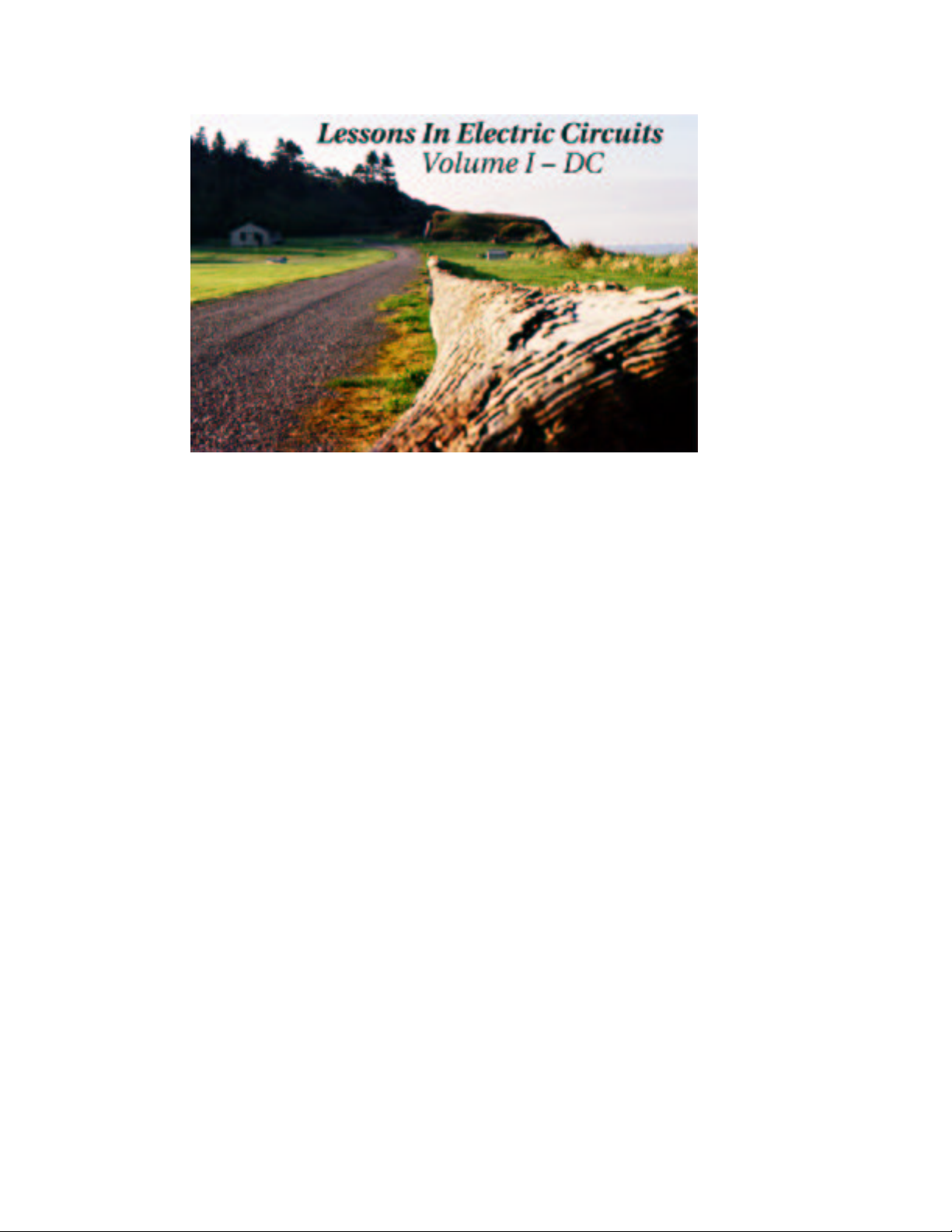
It was discovered centuries ago that certain types of materials would mysteriously attract one another
after being rubbed together. For example: after rubbing a piece of silk against a piece of glass, the
silk and glass would tend to stick together. Indeed, there was an attractive force that could be
demonstrated even when the two materials were separated:
attraction
Glass rod Silk cloth
Glass and silk aren’t the only materials known to behave like this. Anyone who has ever brushed
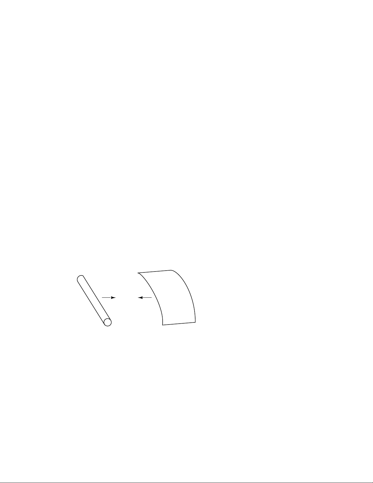
up against a latex balloon only to find that it tries to stick to them has experienced this same phenomenon. Paraffin wax and wool cloth are another pair of materials early experimenters recognized
as manifesting attractive forces after being rubbed together:
1
Page 12
2 CHAPTER 1. BASIC CONCEPTS OF ELECTRICITY
attraction
Wax
Wool cloth
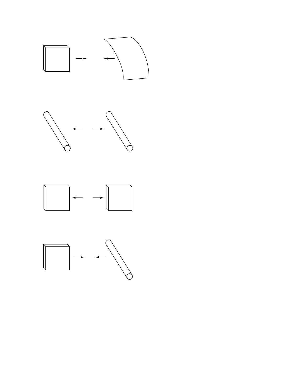
This phenomenon became even more interesting when it was discovered that identical materials,
after having been rubbed with their respective cloths, always repelled each other:
repulsion
Glass rod Glass rod
repulsion
Wax
It was also noted that when a piece of glass rubbed with silk was exposed to a piece of wax
rubbed with wool, the two materials would attract one another:
Wax
attraction
Wax
Glass rod
Furthermore, it was found that any material demonstrating properties of attraction or repulsion
Page 13
1.1. STATIC ELECTRICITY 3
after being rubbed could be classed into one of two distinct categories: attracted to glass and repelled
by wax, or repelled by glass and attracted to wax. It was either one or the other: there were no
materials found that would be attracted to or repelled by both glass and wax, or that reacted to
one without reacting to the other.
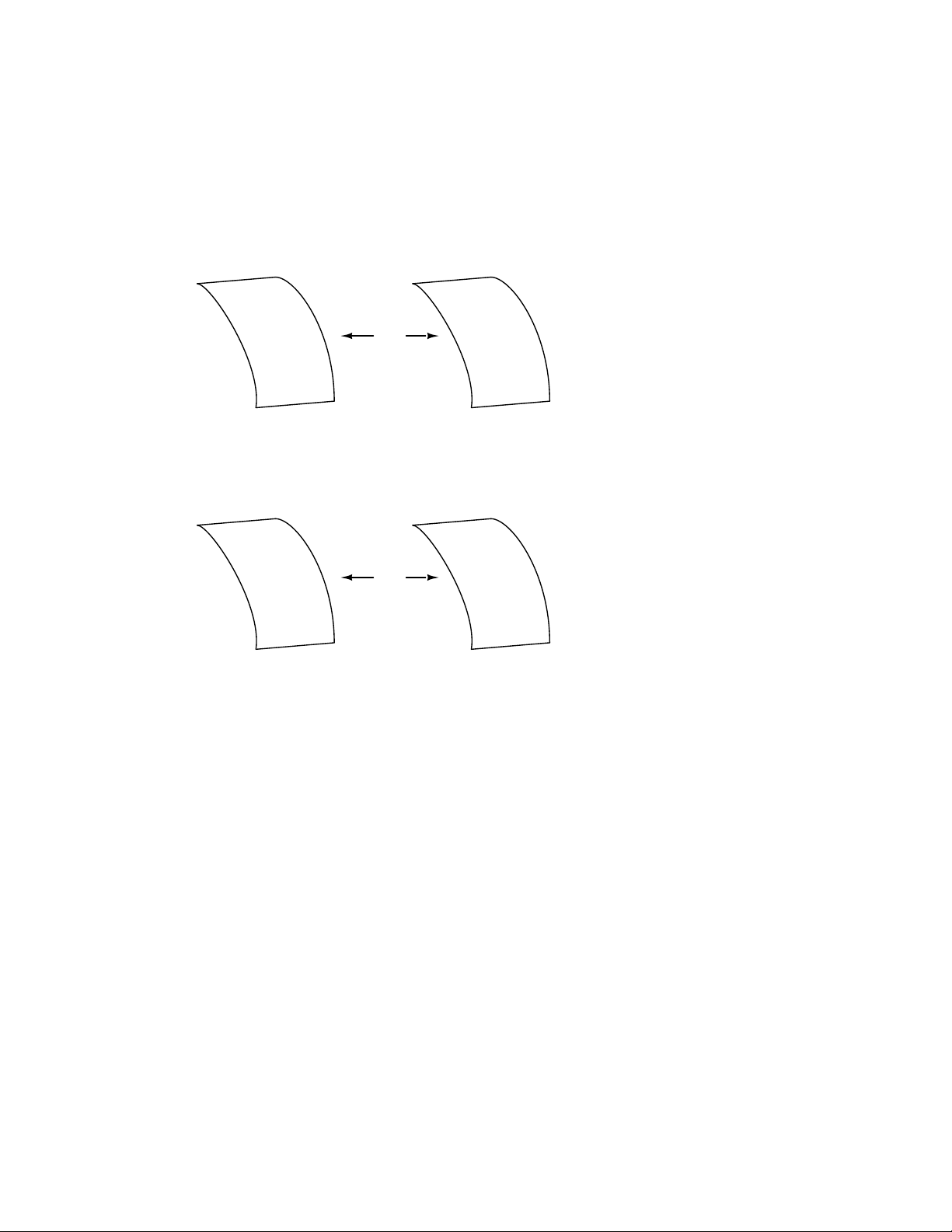
More attention was directed toward the pieces of cloth used to do the rubbing. It was discovered
that after rubbing two pieces of glass with two pieces of silk cloth, not only did the glass pieces repel
each other, but so did the cloths. The same phenomenon held for the pieces of wool used to rub the
wax:
repulsion
Silk clothSilk cloth
repulsion
Wool cloth Wool cloth
Now, this was really strange to witness. After all, none of these objects were visibly altered by
the rubbing, yet they definitely behaved differently than before they were rubbed. Whatever change
took place to make these materials attract or repel one another was invisible.
Some experimenters speculated that invisible ”fluids” were being transferred from one object to
another during the process of rubbing, and that these ”fluids” were able to effect a physical force
over a distance. Charles Dufay was one the early experimenters who demonstrated that there were
definitely two different types of changes wrought by rubbing certain pairs of objects together. The
fact that there was more than one type of change manifested in these materials was evident by the
fact that there were two types of forces produced: attraction and repulsion. The hypothetical fluid
transfer became known as a charge.
One pioneering researcher, Benjamin Franklin, came to the conclusion that there was only one
fluid exchanged between rubbed objects, and that the two different ”charges” were nothing more
than either an excess or a deficiency of that one fluid. After experimenting with wax and wool,
Franklin suggested that the coarse wool removed some of this invisible fluid from the smooth wax,
causing an excess of fluid on the wool and a deficiency of fluid on the wax. The resulting disparity
Page 14

4 CHAPTER 1. BASIC CONCEPTS OF ELECTRICITY
in fluid content between the wool and wax would then cause an attractive force, as the fluid tried
to regain its former balance between the two materials.
Postulating the existence of a single ”fluid” that was either gained or lost through rubbing
accounted best for the observed behavior: that all these materials fell neatly into one of two categories
when rubbed, and most importantly, that the two active materials rubbed against each other always
fell into opposing categories as evidenced by their invariable attraction to one another. In other
words, there was never a time where two materials rubbed against each other both became either
positive or negative.
Following Franklin’s speculation of the wool rubbing something off of the wax, the type of charge
that was associated with rubbed wax became known as ”negative” (because it was supposed to have
a deficiency of fluid) while the type of charge associated with the rubbing wool became known as
”positive” (because it was supposed to have an excess of fluid). Little did he know that his innocent
conjecture would cause much confusion for students of electricity in the future!
Precise measurements of electrical charge were carried out by the French physicist Charles
Coulomb in the 1780’s using a device called a torsional balance measuring the force generated
between two electrically charged objects. The results of Coulomb’s work led to the development of
a unit of electrical charge named in his honor, the coulomb. If two ”point” objects (hypothetical
objects having no appreciable surface area) were equally charged to a measure of 1 coulomb, and
placed 1 meter (approximately 1 yard) apart, they would generate a force of about 9 billion newtons
(approximately 2 billion pounds), either attracting or repelling depending on the types of charges
involved.
It discovered much later that this ”fluid” was actually composed of extremely small bits of matter
called electrons, so named in honor of the ancient Greek word for amber: another material exhibiting
charged properties when rubbed with cloth. Experimentation has since revealed that all objects are
composed of extremely small ”building-blocks” known as atoms, and that these atoms are in turn
composed of smaller components known as particles. The three fundamental particles comprising
atoms are called protons, neutrons, and electrons. Atoms are far too small to be seen, but if we
could look at one, it might appear something like this:
Page 15

1.1. STATIC ELECTRICITY 5
e
e
N
P
P
N
e e
N
N
P
P
P
P
N
N
e
e
e
= electron
P
= proton
N
= neutron
Even though each atom in a piece of material tends to hold together as a unit, there’s actually
a lot of empty space between the electrons and the cluster of protons and neutrons residing in the
middle.
This crude model is that of the element carbon, with six protons, six neutrons, and six electrons.
In any atom, the protons and neutrons are very tightly bound together, which is an important
quality. The tightly-bound clump of protons and neutrons in the center of the atom is called the
nucleus, and the number of protons in an atom’s nucleus determines its elemental identity: change
the number of protons in an atom’s nucleus, and you change the type of atom that it is. In fact,
if you could remove three protons from the nucleus of an atom of lead, you will have achieved the
old alchemists’ dream of producing an atom of gold! The tight binding of protons in the nucleus
is responsible for the stable identity of chemical elements, and the failure of alchemists to achieve
their dream.
Neutrons are much less influential on the chemical character and identity of an atom than protons,
although they are just as hard to add to or remove from the nucleus, being so tightly bound. If
neutrons are added or gained, the atom will still retain the same chemical identity, but its mass will
change slightly and it may acquire strange nuclear properties such as radioactivity.
However, electrons have significantly more freedom to move around in an atom than either
protons or neutrons. In fact, they can be knocked out of their respective positions (even leaving the
atom entirely!) by far less energy than what it takes to dislodge particles in the nucleus. If this
happens, the atom still retains its chemical identity, but an important imbalance occurs. Electrons
and protons are unique in the fact that they are attracted to one another over a distance. It is this
attraction over distance which causes the attraction between rubbed objects, where electrons are
moved away from their original atoms to reside around atoms of another object.
Electrons tend to repel other electrons over a distance, as do protons with other protons. The
only reason protons bind together in the nucleus of an atom is because of a much stronger force
Page 16

6 CHAPTER 1. BASIC CONCEPTS OF ELECTRICITY
called the strong nuclear force which has effect only under very short distances. Because of this
attraction/repulsion behavior between individual particles, electrons and protons are said to have
opposite electric charges. That is, each electron has a negative charge, and each proton a positive
charge. In equal numbers within an atom, they counteract each other’s presence so that the net
charge within the atom is zero. This is why the picture of a carbon atom had six electrons: to balance
out the electric charge of the six protons in the nucleus. If electrons leave or extra electrons arrive,
the atom’s net electric charge will be imbalanced, leaving the atom ”charged” as a whole, causing it
to interact with charged particles and other charged atoms nearby. Neutrons are neither attracted
to or repelled by electrons, protons, or even other neutrons, and are consequently categorized as
having no charge at all.
The process of electrons arriving or leaving is exactly what happens when certain combinations
of materials are rubbed together: electrons from the atoms of one material are forced by the rubbing
to leave their respective atoms and transfer over to the atoms of the other material. In other words,
electrons comprise the ”fluid” hypothesized by Benjamin Franklin. The operational definition of a
coulomb as the unit of electrical charge (in terms of force generated between point charges) was
found to be equal to an excess or deficiency of about 6,250,000,000,000,000,000 electrons. Or, stated
in reverse terms, one electron has a charge of about 0.00000000000000000016 coulombs. Being that
one electron is the smallest known carrier of electric charge, this last figure of charge for the electron
is defined as the elementary charge.
The result of an imbalance of this ”fluid” (electrons) between objects is called static electricity.
It is called ”static” because the displaced electrons tend to remain stationary after being moved
from one material to another. In the case of wax and wool, it was determined through further
experimentation that electrons in the wool actually transferred to the atoms in the wax, which is
exactly opposite of Franklin’s conjecture! In honor of Franklin’s designation of the wax’s charge
being ”negative” and the wool’s charge being ”positive,” electrons are said to have a ”negative”
charging influence. Thus, an object whose atoms have received a surplus of electrons is said to be
negatively charged, while an object whose atoms are lacking electrons is said to be positively charged,
as confusing as these designations may seem. By the time the true nature of electric ”fluid” was
discovered, Franklin’s nomenclature of electric charge was too well established to be easily changed,
and so it remains to this day.
• REVIEW:
• All materials are made up of tiny ”building blocks” known as atoms.
• All atoms contain particles called electrons, protons, and neutrons.
• Electrons have a negative (-) electric charge.
• Protons have a positive (+) electric charge.
• Neutrons have no electric charge.
• Electrons can be dislodged from atoms much easier than protons or neutrons.
• The number of protons in an atom’s nucleus determines its identity as a unique element.
Page 17

1.2. CONDUCTORS, INSULATORS, AND ELECTRON FLOW 7
1.2 Conductors, insulators, and electron flow
The electrons of different types of atoms have different degrees of freedom to move around. With
some types of materials, such as metals, the outermost electrons in the atoms are so loosely bound
that they chaotically move in the space between the atoms of that material by nothing more than
the influence of room-temperature heat energy. Because these virtually unbound electrons are free
to leave their respective atoms and float around in the space between adjacent atoms, they are often
called free electrons.
In other types of materials such as glass, the atoms’ electrons have very little freedom to move
around. While external forces such as physical rubbing can force some of these electrons to leave
their respective atoms and transfer to the atoms of another material, they do not move between
atoms within that material very easily.
This relative mobility of electrons within a material is known as electric conductivity. Conductivity is determined by the types of atoms in a material (the number of protons in each atom’s
nucleus, determining its chemical identity) and how the atoms are linked together with one another.
Materials with high electron mobility (many free electrons) are called conductors, while materials
with low electron mobility (few or no free electrons) are called insulators.
Here are a few common examples of conductors and insulators:
• Conductors:
• silver
• copper
• gold
• aluminum
• iron
• steel
• brass
• bronze
• mercury
• graphite
• dirty water
• concrete
• Insulators:
• glass
Page 18

8 CHAPTER 1. BASIC CONCEPTS OF ELECTRICITY
• rubber
• oil
• asphalt
• fiberglass
• porcelain
• ceramic
• quartz
• (dry) cotton
• (dry) paper
• (dry) wood
• plastic
• air
• diamond
• pure water
It must be understood that not all conductive materials have the same level of conductivity,
and not all insulators are equally resistant to electron motion. Electrical conductivity is analogous
to the transparency of certain materials to light: materials that easily ”conduct” light are called
”transparent,” while those that don’t are called ”opaque.” However, not all transparent materials
are equally conductive to light. Window glass is better than most plastics, and certainly better than
”clear” fiberglass. So it is with electrical conductors, some being better than others.
For instance, silver is the best conductor in the ”conductors” list, offering easier passage for
electrons than any other material cited. Dirty water and concrete are also listed as conductors, but
these materials are substantially less conductive than any metal.
Physical dimension also impacts conductivity. For instance, if we take two strips of the same
conductive material – one thin and the other thick – the thick strip will prove to be a better conductor
than the thin for the same length. If we take another pair of strips – this time both with the same
thickness but one shorter than the other – the shorter one will offer easier passage to electrons than
the long one. This is analogous to water flow in a pipe: a fat pipe offers easier passage than a skinny
pipe, and a short pipe is easier for water to move through than a long pipe, all other dimensions
being equal.
It should also be understood that some materials experience changes in their electrical properties
under different conditions. Glass, for instance, is a very good insulator at room temperature, but
becomes a conductor when heated to a very high temperature. Gases such as air, normally insulating
materials, also become conductive if heated to very high temperatures. Most metals become poorer
conductors when heated, and better conductors when cooled. Many conductive materials become
perfectly conductive (this is called superconductivity) at extremely low temperatures.
Page 19
1.2. CONDUCTORS, INSULATORS, AND ELECTRON FLOW 9
While the normal motion of ”free” electrons in a conductor is random, with no particular direction or speed, electrons can be influenced to move in a coordinated fashion through a conductive
material. This uniform motion of electrons is what we call electricity, or electric current. To be
more precise, it could be called dynamic electricity in contrast to static electricity, which is an unmoving accumulation of electric charge. Just like water flowing through the emptiness of a pipe,
electrons are able to move within the empty space within and between the atoms of a conductor.
The conductor may appear to be solid to our eyes, but any material composed of atoms is mostly
empty space! The liquid-flow analogy is so fitting that the motion of electrons through a conductor
is often referred to as a ”flow.”
A noteworthy observation may be made here. As each electron moves uniformly through a
conductor, it pushes on the one ahead of it, such that all the electrons move together as a group.
The starting and stopping of electron flow through the length of a conductive path is virtually
instantaneous from one end of a conductor to the other, even though the motion of each electron
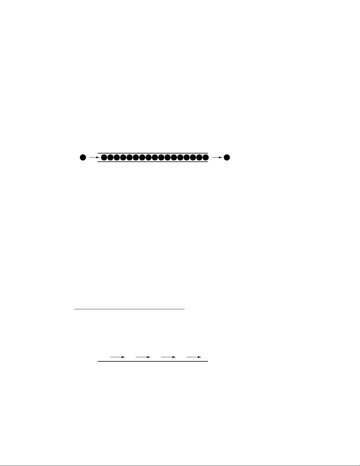
may be very slow. An approximate analogy is that of a tube filled end-to-end with marbles:
Tube
Marble Marble
The tube is full of marbles, just as a conductor is full of free electrons ready to be moved by an
outside influence. If a single marble is suddenly inserted into this full tube on the left-hand side,
another marble will immediately try to exit the tube on the right. Even though each marble only
traveled a short distance, the transfer of motion through the tube is virtually instantaneous from
the left end to the right end, no matter how long the tube is. With electricity, the overall effect
from one end of a conductor to the other happens at the speed of light: a swift 186,000 miles per
second!!! Each individual electron, though, travels through the conductor at a much slower pace.
If we want electrons to flow in a certain direction to a certain place, we must provide the proper
path for them to move, just as a plumber must install piping to get water to flow where he or she
wants it to flow. To facilitate this, wires are made of highly conductive metals such as copper or
aluminum in a wide variety of sizes.
Remember that electrons can flow only when they have the opportunity to move in the space
between the atoms of a material. This means that there can be electric current only where there
exists a continuous path of conductive material providing a conduit for electrons to travel through. In
the marble analogy, marbles can flow into the left-hand side of the tube (and, consequently, through
the tube) if and only if the tube is open on the right-hand side for marbles to flow out. If the tube
is blocked on the right-hand side, the marbles will just ”pile up” inside the tube, and marble ”flow”
will not occur. The same holds true for electric current: the continuous flow of electrons requires
there be an unbroken path to permit that flow. Let’s look at a diagram to illustrate how this works:
A thin, solid line (as shown above) is the conventional symbol for a continuous piece of wire.
Since the wire is made of a conductive material, such as copper, its constituent atoms have many
free electrons which can easily move through the wire. However, there will never be a continuous or
uniform flow of electrons within this wire unless they have a place to come from and a place to go.
Let’s add an hypothetical electron ”Source” and ”Destination:”
Electron Electron
Source Destination
Page 20
10 CHAPTER 1. BASIC CONCEPTS OF ELECTRICITY
Now, with the Electron Source pushing new electrons into the wire on the left-hand side, electron
flow through the wire can occur (as indicated by the arrows pointing from left to right). However,
the flow will be interrupted if the conductive path formed by the wire is broken:
Electron Electron
Source Destination
no flow! no flow!
(break)
Since air is an insulating material, and an air gap separates the two pieces of wire, the oncecontinuous path has now been broken, and electrons cannot flow from Source to Destination. This
is like cutting a water pipe in two and capping off the broken ends of the pipe: water can’t flow if
there’s no exit out of the pipe. In electrical terms, we had a condition of electrical continuity when
the wire was in one piece, and now that continuity is broken with the wire cut and separated.
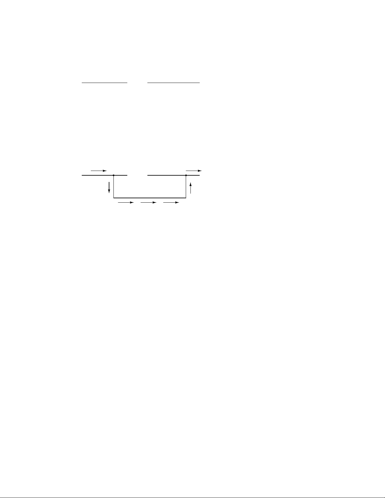
If we were to take another piece of wire leading to the Destination and simply make physical
contact with the wire leading to the Source, we would once again have a continuous path for electrons
to flow. The two dots in the diagram indicate physical (metal-to-metal) contact between the wire
pieces:
Electron Electron
Source Destination
(break)
no flow!
Now, we have continuity from the Source, to the newly-made connection, down, to the right, and
up to the Destination. This is analogous to putting a ”tee” fitting in one of the capped-off pipes and
directing water through a new segment of pipe to its destination. Please take note that the broken
segment of wire on the right hand side has no electrons flowing through it, because it is no longer
part of a complete path from Source to Destination.
It is interesting to note that no ”wear” occurs within wires due to this electric current, unlike
water-carrying pipes which are eventually corroded and worn by prolonged flows. Electrons do
encounter some degree of friction as they move, however, and this friction can generate heat in a
conductor. This is a topic we’ll explore in much greater detail later.
• REVIEW:
• In conductive materials, the outer electrons in each atom can easily come or go, and are called
free electrons.
• In insulating materials, the outer electrons are not so free to move.
• All metals are electrically conductive.
• Dynamic electricity, or electric current, is the uniform motion of electrons through a conductor.
Static electricity is an unmoving, accumulated charge formed by either an excess or deficiency
of electrons in an object.
• For electrons to flow continuously (indefinitely) through a conductor, there must be a complete,
unbroken path for them to move both into and out of that conductor.
Page 21
1.3. ELECTRIC CIRCUITS 11
1.3 Electric circuits
You might have been wondering how electrons can continuously flow in a uniform direction through
wires without the benefit of these hypothetical electron Sources and Destinations. In order for the
Source-and-Destination scheme to work, both would have to have an infinite capacity for electrons
in order to sustain a continuous flow! Using the marble-and-tube analogy, the marble source and
marble destination buckets would have to be infinitely large to contain enough marble capacity for
a ”flow” of marbles to be sustained.
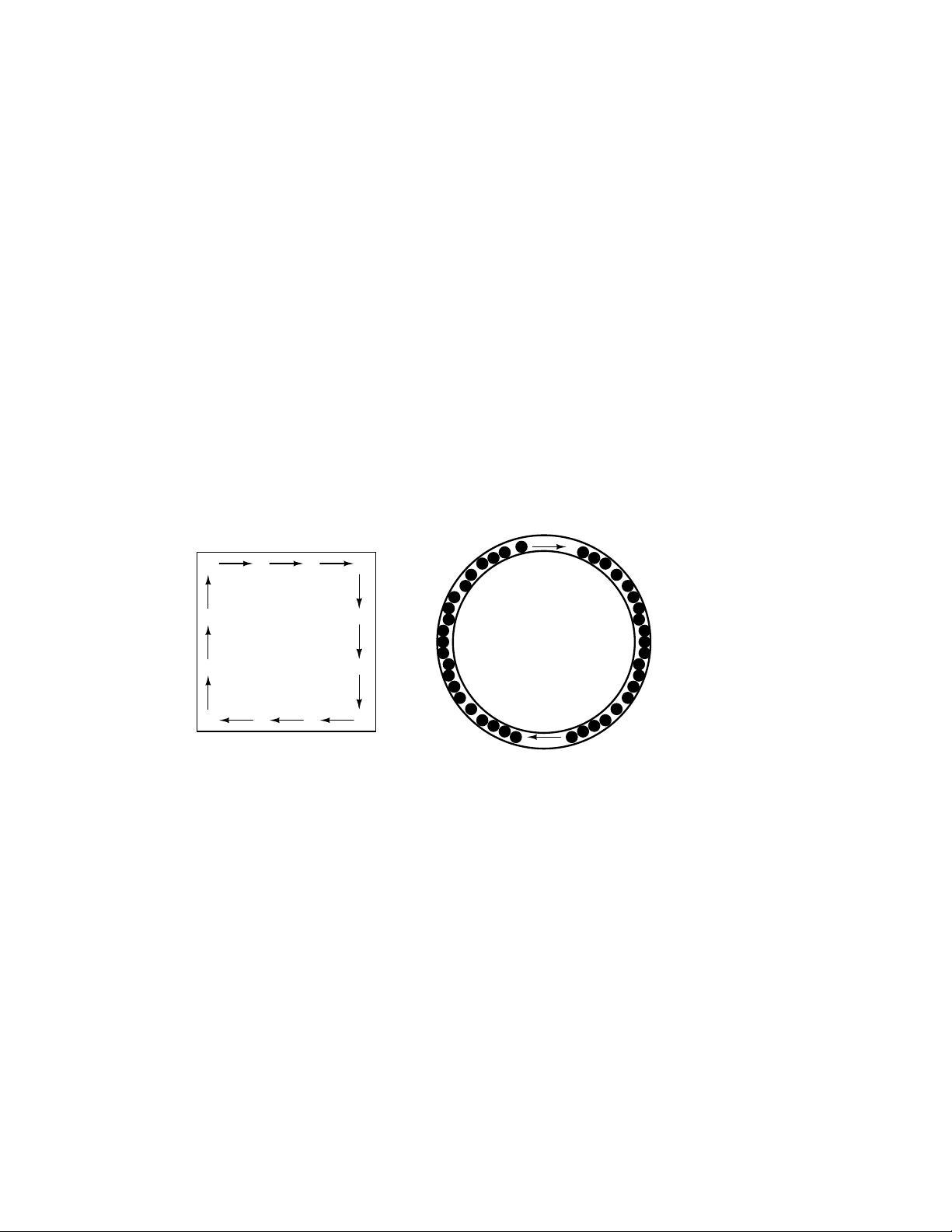
The answer to this paradox is found in the concept of a circuit: a never-ending looped pathway
for electrons. If we take a wire, or many wires joined end-to-end, and loop it around so that it forms
a continuous pathway, we have the means to support a uniform flow of electrons without having to
resort to infinite Sources and Destinations:
electrons can flow
in a path without
beginning or end,
continuing forever!
A marble-and-
hula-hoop "circuit"
Each electron advancing clockwise in this circuit pushes on the one in front of it, which pushes
on the one in front of it, and so on, and so on, just like a hula-hoop filled with marbles. Now, we
have the capability of supporting a continuous flow of electrons indefinitely without the need for
infinite electron supplies and dumps. All we need to maintain this flow is a continuous means of
motivation for those electrons, which we’ll address in the next section of this chapter.
It must be realized that continuity is just as important in a circuit as it is in a straight piece
of wire. Just as in the example with the straight piece of wire between the electron Source and
Destination, any break in this circuit will prevent electrons from flowing through it:
Page 22

12 CHAPTER 1. BASIC CONCEPTS OF ELECTRICITY
no flow!
continuous
electron flow cannot
occur anywhere
in a "broken" circuit!
(break)
no flow!
no flow!
An important principle to realize here is that it doesn’t matter where the break occurs. Any
discontinuity in the circuit will prevent electron flow throughout the entire circuit. Unless there is
a continuous, unbroken loop of conductive material for electrons to flow through, a sustained flow
simply cannot be maintained.
no flow!
continuous
electron flow cannot
occur anywhere
in a "broken" circuit!
no flow!
(break)
no flow!
• REVIEW:
• A circuit is an unbroken loop of conductive material that allows electrons to flow through
continuously without beginning or end.
• If a circuit is ”broken,” that means it’s conductive elements no longer form a complete path,
and continuous electron flow cannot occur in it.
• The location of a break in a circuit is irrelevant to its inability to sustain continuous electron
flow. Any break, anywhere in a circuit prevents electron flow throughout the circuit.
Page 23
1.4. VOLTAGE AND CURRENT 13
1.4 Voltage and current
As was previously mentioned, we need more than just a continuous path (circuit) before a continuous
flow of electrons will occur: we also need some means to push these electrons around the circuit.
Just like marbles in a tube or water in a pipe, it takes some kind of influencing force to initiate flow.
With electrons, this force is the same force at work in static electricity: the force produced by an
imbalance of electric charge.
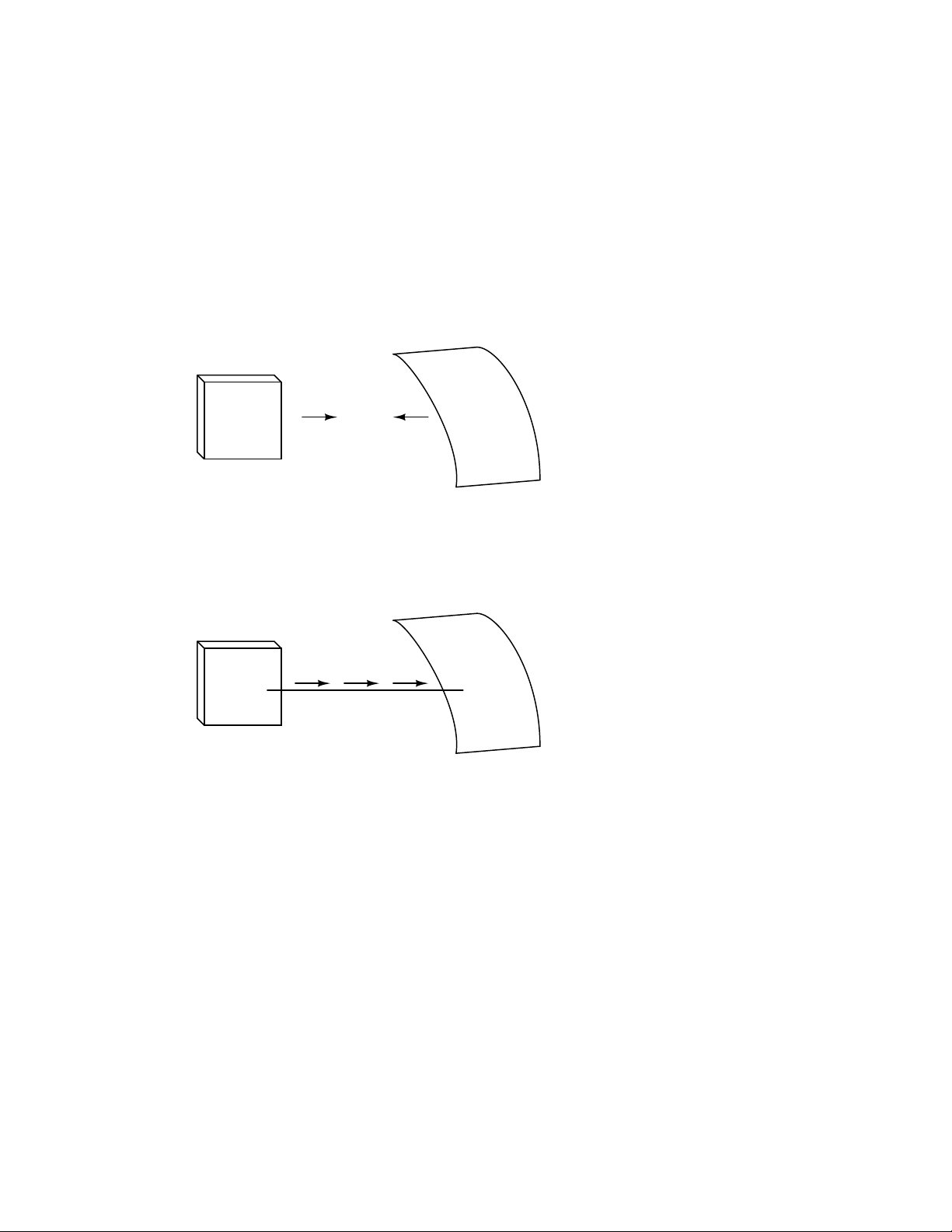
If we take the examples of wax and wool which have been rubbed together, we find that the
surplus of electrons in the wax (negative charge) and the deficit of electrons in the wool (positive
charge) creates an imbalance of charge between them. This imbalance manifests itself as an attractive
force between the two objects:
---
-
-
- -
- -
-
-
--Wax
+ +
- -
-
--
-
-
-
--
-
-
-
-
---
-
attraction
+
+
++
+++
+
+
+
+
+
+
+
+
+
+
+
+++
+
+
+
+
+
+
+
+
+
+ +
+
+
+
+
+
+
+
+
+
Wool cloth
If a conductive wire is placed between the charged wax and wool, electrons will flow through it,
as some of the excess electrons in the wax rush through the wire to get back to the wool, filling the
deficiency of electrons there:
+
+
+
+
+
+
+
+
+++
+
+
+
+ +
+
+
+
+
+
+
+
+
+
-
- -
-
-
-
---
-
-
-
-
-
-
-
-
-
Wax
+ + +
-
electron flow
- - wire
Wool cloth
The imbalance of electrons between the atoms in the wax and the atoms in the wool creates a
force between the two materials. With no path for electrons to flow from the wax to the wool, all
this force can do is attract the two objects together. Now that a conductor bridges the insulating
gap, however, the force will provoke electrons to flow in a uniform direction through the wire, if
only momentarily, until the charge in that area neutralizes and the force between the wax and wool
diminishes.
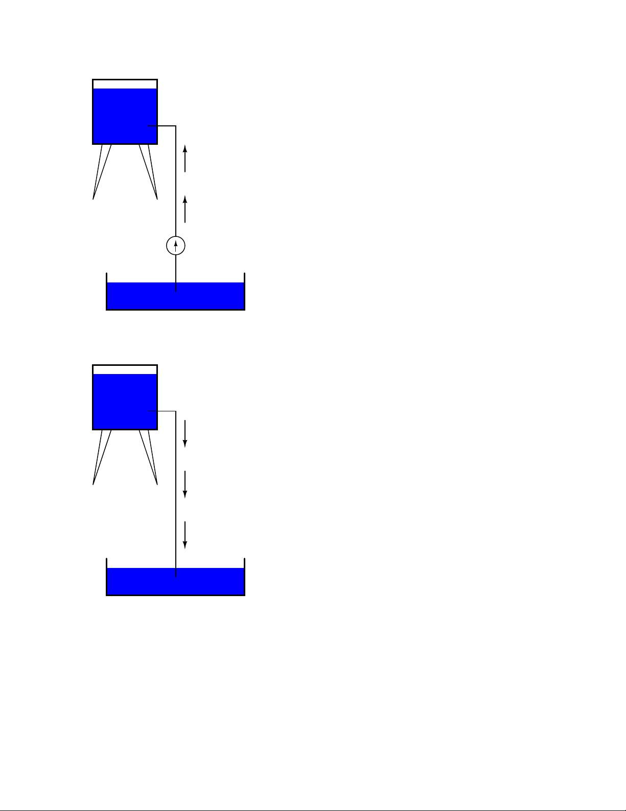
The electric charge formed between these two materials by rubbing them together serves to store
a certain amount of energy. This energy is not unlike the energy stored in a high reservoir of water
that has been pumped from a lower-level pond:
Page 24
14 CHAPTER 1. BASIC CONCEPTS OF ELECTRICITY
Reservoir
Energy stored
Water flow
Pump
Pond
The influence of gravity on the water in the reservoir creates a force that attempts to move the
water down to the lower level again. If a suitable pipe is run from the reservoir back to the pond,
water will flow under the influence of gravity down from the reservoir, through the pipe:
Reservoir
Energy released
Pond
It takes energy to pump that water from the low-level pond to the high-level reservoir, and the
movement of water through the piping back down to its original level constitutes a releasing of
energy stored from previous pumping.
Page 25
1.4. VOLTAGE AND CURRENT 15
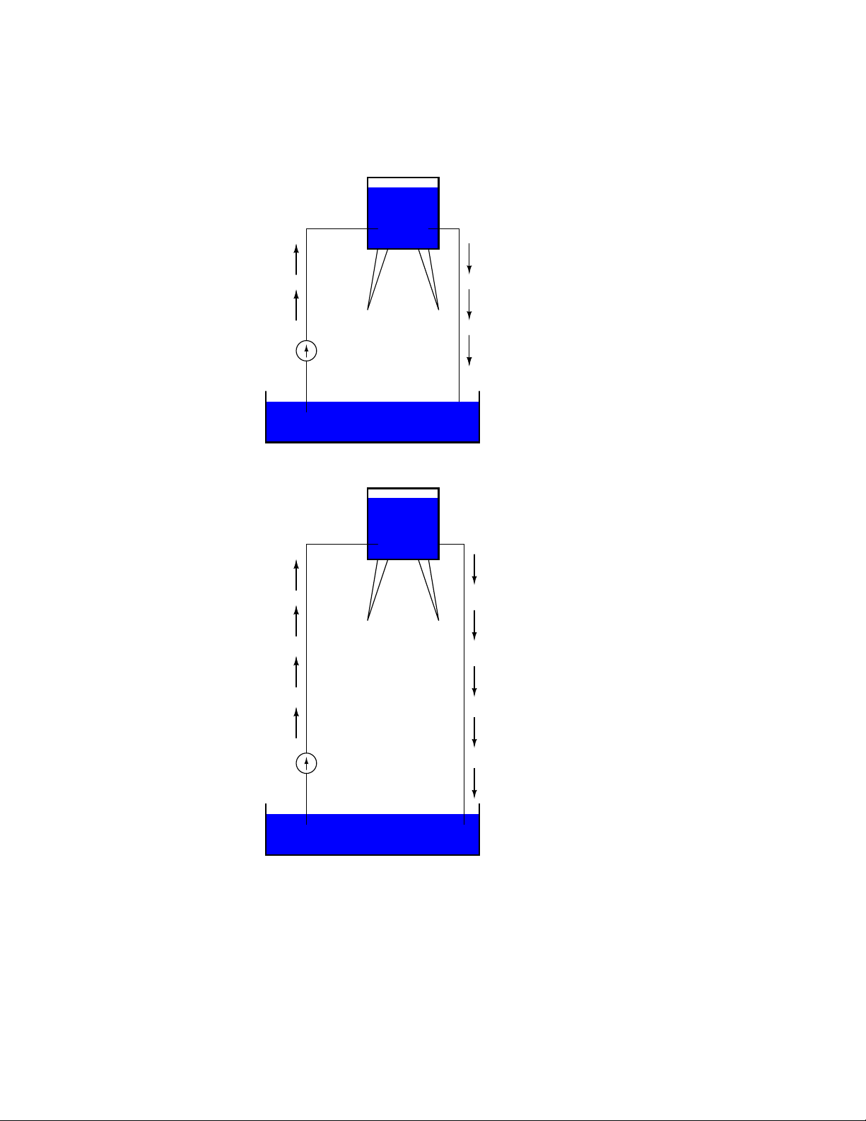
If the water is pumped to an even higher level, it will take even more energy to do so, thus more
energy will be stored, and more energy released if the water is allowed to flow through a pipe back
down again:
Reservoir
Energy stored
Energy released
Pump
Pond
Reservoir
More energy stored
Pump
Pond
More energy released
Electrons are not much different. If we rub wax and wool together, we ”pump” electrons away
Page 26

16 CHAPTER 1. BASIC CONCEPTS OF ELECTRICITY
from their normal ”levels,” creating a condition where a force exists between the wax and wool, as
the electrons seek to re-establish their former positions (and balance within their respective atoms).
The force attracting electrons back to their original positions around the positive nuclei of their
atoms is analogous to the force gravity exerts on water in the reservoir, trying to draw it down to
its former level.
Just as the pumping of water to a higher level results in energy being stored, ”pumping” electrons
to create an electric charge imbalance results in a certain amount of energy being stored in that
imbalance. And, just as providing a way for water to flow back down from the heights of the reservoir
results in a release of that stored energy, providing a way for electrons to flow back to their original
”levels” results in a release of stored energy.
When the electrons are poised in that static condition (just like water sitting still, high in a
reservoir), the energy stored there is called potential energy, because it has the possibility (potential)
of release that has not been fully realized yet. When you scuff your rubber-soled shoes against a
fabric carpet on a dry day, you create an imbalance of electric charge between yourself and the
carpet. The action of scuffing your feet stores energy in the form of an imbalance of electrons forced
from their original locations. If this charge (static electricity) is stationary, and you won’t realize
that energy is being stored at all. However, once you place your hand against a metal doorknob
(with lots of electron mobility to neutralize your electric charge), that stored energy will be released
in the form of a sudden flow of electrons through your hand, and you will perceive it as an electric
shock!
This potential energy, stored in the form of an electric charge imbalance and capable of provoking
electrons to flow through a conductor, can be expressed as a term called voltage, which technically is
a measure of potential energy per unit charge of electrons, or something a physicist would call specific
potential energy. Defined in the context of static electricity, voltage is the measure of work required
to move a unit charge from one location to another, against the force which tries to keep electric
charges balanced. In the context of electrical power sources, voltage is the amount of potential
energy available (work to be done) per unit charge, to move electrons through a conductor.
Because voltage is an expression of potential energy, representing the possibility or potential for
energy release as the electrons move from one ”level” to another, it is always referenced between
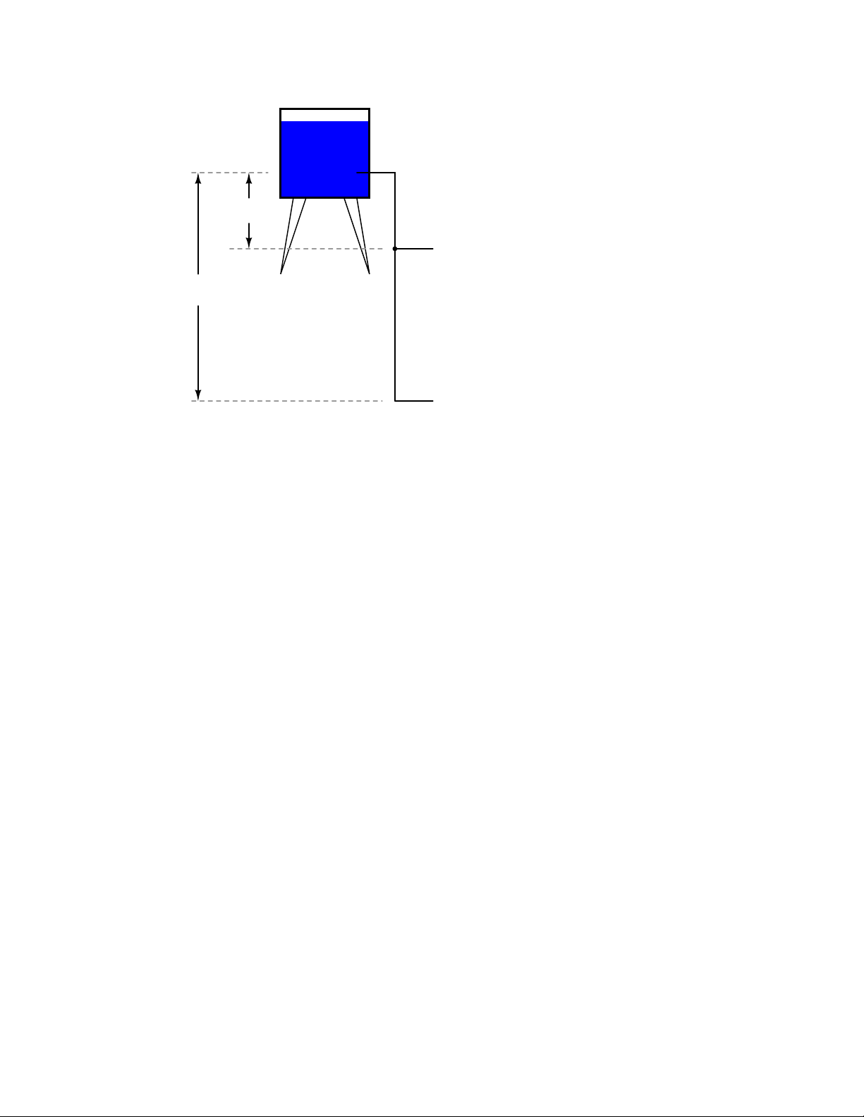
two points. Consider the water reservoir analogy:
Page 27
1.4. VOLTAGE AND CURRENT 17
Reservoir
Drop
Location #1
Drop
Location #2
Because of the difference in the height of the drop, there’s potential for much more energy to be
released from the reservoir through the piping to location 2 than to location 1. The principle can be
intuitively understood in dropping a rock: which results in a more violent impact, a rock dropped
from a height of one foot, or the same rock dropped from a height of one mile? Obviously, the drop
of greater height results in greater energy released (a more violent impact). We cannot assess the
amount of stored energy in a water reservoir simply by measuring the volume of water any more
than we can predict the severity of a falling rock’s impact simply from knowing the weight of the
rock: in both cases we must also consider how far these masses will drop from their initial height.
The amount of energy released by allowing a mass to drop is relative to the distance between its
starting and ending points. Likewise, the potential energy available for moving electrons from one
point to another is relative to those two points. Therefore, voltage is always expressed as a quantity
between two points. Interestingly enough, the analogy of a mass potentially ”dropping” from one
height to another is such an apt model that voltage between two points is sometimes called a voltage
drop.
Voltage can be generated by means other than rubbing certain types of materials against each
other. Chemical reactions, radiant energy, and the influence of magnetism on conductors are a few
ways in which voltage may be produced. Respective examples of these three sources of voltage
are batteries, solar cells, and generators (such as the ”alternator” unit under the hood of your
automobile). For now, we won’t go into detail as to how each of these voltage sources works – more
important is that we understand how voltage sources can be applied to create electron flow in a
circuit.
Let’s take the symbol for a chemical battery and build a circuit step by step:
Page 28
18 CHAPTER 1. BASIC CONCEPTS OF ELECTRICITY
1
Battery
+
2
Any source of voltage, including batteries, have two points for electrical contact. In this case,
we have point 1 and point 2 in the above diagram. The horizontal lines of varying length indicate
that this is a battery, and they further indicate the direction which this battery’s voltage will try
to push electrons through a circuit. The fact that the horizontal lines in the battery symbol appear
separated (and thus unable to serve as a path for electrons to move) is no cause for concern: in real
life, those horizontal lines represent metallic plates immersed in a liquid or semi-solid material that
not only conducts electrons, but also generates the voltage to push them along by interacting with
the plates.
Notice the little ”+” and ”-” signs to the immediate left of the battery symbol. The negative
(-) end of the battery is always the end with the shortest dash, and the positive (+) end of the
battery is always the end with the longest dash. Since we have decided to call electrons ”negatively”
charged (thanks, Ben!), the negative end of a battery is that end which tries to push electrons out
of it. Likewise, the positive end is that end which tries to attract electrons.
With the ”+” and ”-” ends of the battery not connected to anything, there will be voltage
between those two points, but there will be no flow of electrons through the battery, because there
is no continuous path for the electrons to move.
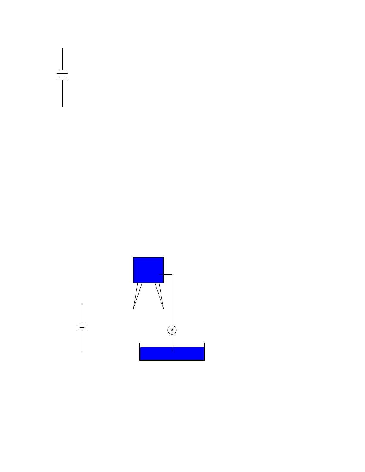
Water analogy
Reservoir
Electric Battery
No flow
1
Battery
+
2
No flow (once the
reservoir has been
completely filled)
Pump
Pond
The same principle holds true for the water reservoir and pump analogy: without a return pipe
Page 29
1.4. VOLTAGE AND CURRENT 19
back to the pond, stored energy in the reservoir cannot be released in the form of water flow. Once
the reservoir is completely filled up, no flow can occur, no matter how much pressure the pump
may generate. There needs to be a complete path (circuit) for water to flow from the pond, to the
reservoir, and back to the pond in order for continuous flow to occur.
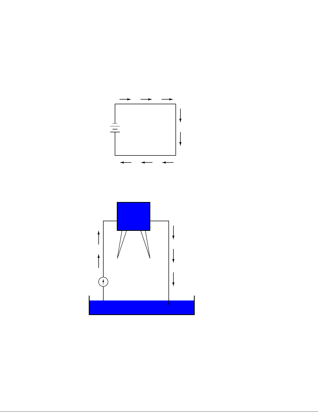
We can provide such a path for the battery by connecting a piece of wire from one end of the
battery to the other. Forming a circuit with a loop of wire, we will initiate a continuous flow of
electrons in a clockwise direction:
Electric Circuit
1
Battery
+
2
electron flow!
Water analogy
Reservoir
water flow!
water flow!
Pump
Pond
So long as the battery continues to produce voltage and the continuity of the electrical path
Page 30
20 CHAPTER 1. BASIC CONCEPTS OF ELECTRICITY
isn’t broken, electrons will continue to flow in the circuit. Following the metaphor of water moving
through a pipe, this continuous, uniform flow of electrons through the circuit is called a current. So
long as the voltage source keeps ”pushing” in the same direction, the electron flow will continue to
move in the same direction in the circuit. This single-direction flow of electrons is called a Direct
Current, or DC. In the second volume of this book series, electric circuits are explored where the
direction of current switches back and forth: Alternating Current, or AC. But for now, we’ll just
concern ourselves with DC circuits.
Because electric current is composed of individual electrons flowing in unison through a conductor
by moving along and pushing on the electrons ahead, just like marbles through a tube or water
through a pipe, the amount of flow throughout a single circuit will be the same at any point. If we
were to monitor a cross-section of the wire in a single circuit, counting the electrons flowing by, we
would notice the exact same quantity per unit of time as in any other part of the circuit, regardless
of conductor length or conductor diameter.
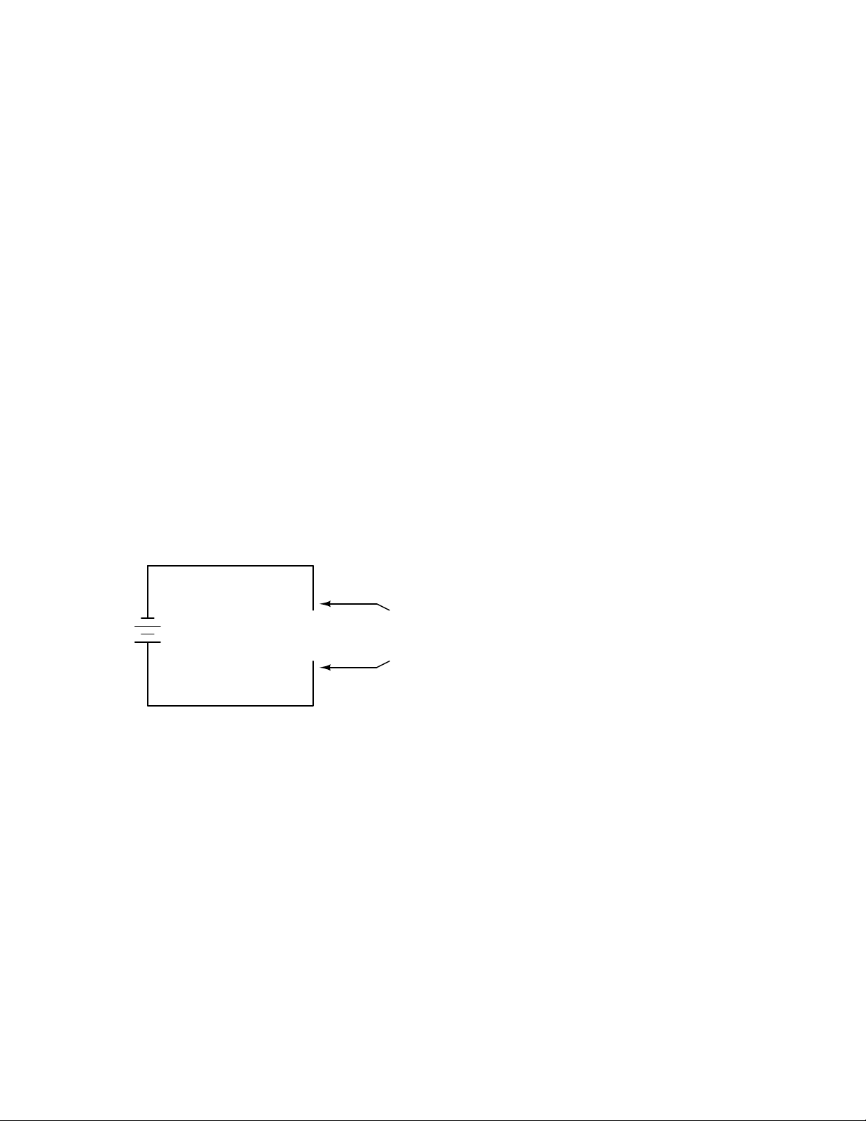
If we break the circuit’s continuity at any point, the electric current will cease in the entire loop,
and the full voltage produced by the battery will be manifested across the break, between the wire
ends that used to be connected:
no flow!
1
Battery
-
(break)
voltage
drop
+
+
2
no flow!
Notice the ”+” and ”-” signs drawn at the ends of the break in the circuit, and how they
correspond to the ”+” and ”-” signs next to the battery’s terminals. These markers indicate the
direction that the voltage attempts to push electron flow, that potential direction commonly referred
to as polarity. Remember that voltage is always relative between two points. Because of this fact,
the polarity of a voltage drop is also relative between two points: whether a point in a circuit gets
labeled with a ”+” or a ”-” depends on the other point to which it is referenced. Take a look at the
following circuit, where each corner of the loop is marked with a number for reference:
Page 31

1.4. VOLTAGE AND CURRENT 21
no flow!
1 2
Battery
-
(break)
+
+
34
no flow!
With the circuit’s continuity broken between points 2 and 3, the polarity of the voltage dropped
between points 2 and 3 is ”-” for point 2 and ”+” for point 3. The battery’s polarity (1 ”-” and
4 ”+”) is trying to push electrons through the loop clockwise from 1 to 2 to 3 to 4 and back to 1
again.
Now let’s see what happens if we connect points 2 and 3 back together again, but place a break
in the circuit between points 3 and 4:
no flow!
1 2
Battery
no flow!
+
-+
34
(break)
With the break between 3 and 4, the polarity of the voltage drop between those two points is
”+” for 4 and ”-” for 3. Take special note of the fact that point 3’s ”sign” is opposite of that in the
first example, where the break was between points 2 and 3 (where point 3 was labeled ”+”). It is
impossible for us to say that point 3 in this circuit will always be either ”+” or ”-”, because polarity,
like voltage itself, is not specific to a single point, but is always relative between two points!
• REVIEW:
• Electrons can be motivated to flow through a conductor by a the same force manifested in
static electricity.
• Voltage is the measure of specific potential energy (potential energy per unit charge) between
two locations. In layman’s terms, it is the measure of ”push” available to motivate electrons.
• Voltage, as an expression of potential energy, is always relative between two locations, or
points. Sometimes it is called a voltage ”drop.”
Page 32

22 CHAPTER 1. BASIC CONCEPTS OF ELECTRICITY
• When a voltage source is connected to a circuit, the voltage will cause a uniform flow of
electrons through that circuit called a current.
• In a single (one loop) circuit, the amount current of current at any point is the same as the
amount of current at any other point.
• If a circuit containing a voltage source is broken, the full voltage of that source will appear
across the points of the break.
• The +/- orientation a voltage drop is called the polarity. It is also relative between two points.
1.5 Resistance
The circuit in the previous section is not a very practical one. In fact, it can be quite dangerous
to build (directly connecting the poles of a voltage source together with a single piece of wire).
The reason it is dangerous is because the magnitude of electric current may be very large in such a
short circuit, and the release of energy very dramatic (usually in the form of heat). Usually, electric
circuits are constructed in such a way as to make practical use of that released energy, in as safe a
manner as possible.
One practical and popular use of electric current is for the operation of electric lighting. The
simplest form of electric lamp is a tiny metal ”filament” inside of a clear glass bulb, which glows
white-hot (”incandesces”) with heat energy when sufficient electric current passes through it. Like
the battery, it has two conductive connection points, one for electrons to enter and the other for
electrons to exit.
Connected to a source of voltage, an electric lamp circuit looks something like this:
electron flow
-
Battery
Electric lamp (glowing)
+
electron flow
As the electrons work their way through the thin metal filament of the lamp, they encounter
more opposition to motion than they typically would in a thick piece of wire. This opposition to
electric current depends on the type of material, its cross-sectional area, and its temperature. It is
technically known as resistance. (It can be said that conductors have low resistance and insulators
have very high resistance.) This resistance serves to limit the amount of current through the circuit
with a given amount of voltage supplied by the battery, as compared with the ”short circuit” where
we had nothing but a wire joining one end of the voltage source (battery) to the other.
Page 33

1.5. RESISTANCE 23
When electrons move against the opposition of resistance, ”friction” is generated. Just like
mechanical friction, the friction produced by electrons flowing against a resistance manifests itself
in the form of heat. The concentrated resistance of a lamp’s filament results in a relatively large
amount of heat energy dissipated at that filament. This heat energy is enough to cause the filament
to glow white-hot, producing light, whereas the wires connecting the lamp to the battery (which
have much lower resistance) hardly even get warm while conducting the same amount of current.
As in the case of the short circuit, if the continuity of the circuit is broken at any point, electron
flow stops throughout the entire circuit. With a lamp in place, this means that it will stop glowing:
no flow! no flow!
(break)
- +
-
Battery
+
voltage
drop
Electric lamp
(not glowing)
no flow!
As before, with no flow of electrons, the entire potential (voltage) of the battery is available
across the break, waiting for the opportunity of a connection to bridge across that break and permit
electron flow again. This condition is known as an open circuit, where a break in the continuity of the
circuit prevents current throughout. All it takes is a single break in continuity to ”open” a circuit.
Once any breaks have been connected once again and the continuity of the circuit re-established, it
is known as a closed circuit.
What we see here is the basis for switching lamps on and off by remote switches. Because any
break in a circuit’s continuity results in current stopping throughout the entire circuit, we can use a
device designed to intentionally break that continuity (called a switch), mounted at any convenient
location that we can run wires to, to control the flow of electrons in the circuit:
switch
It doesn’t matter how twisted or
-
convoluted a route the wires take
conducting current, so long as they
Battery
+
This is how a switch mounted on the wall of a house can control a lamp that is mounted down a
long hallway, or even in another room, far away from the switch. The switch itself is constructed of
a pair of conductive contacts (usually made of some kind of metal) forced together by a mechanical
form a complete, uninterrupted
loop (circuit).
Page 34

24 CHAPTER 1. BASIC CONCEPTS OF ELECTRICITY
lever actuator or pushbutton. When the contacts touch each other, electrons are able to flow from
one to the other and the circuit’s continuity is established; when the contacts are separated, electron
flow from one to the other is prevented by the insulation of the air between, and the circuit’s
continuity is broken.
Perhaps the best kind of switch to show for illustration of the basic principle is the ”knife” switch:
A knife switch is nothing more than a conductive lever, free to pivot on a hinge, coming into
physical contact with one or more stationary contact points which are also conductive. The switch
shown in the above illustration is constructed on a porcelain base (an excellent insulating material),
using copper (an excellent conductor) for the ”blade” and contact points. The handle is plastic to
insulate the operator’s hand from the conductive blade of the switch when opening or closing it.
Here is another type of knife switch, with two stationary contacts instead of one:
Page 35

1.5. RESISTANCE 25
The particular knife switch shown here has one ”blade” but two stationary contacts, meaning
that it can make or break more than one circuit. For now this is not terribly important to be aware
of, just the basic concept of what a switch is and how it works.
Knife switches are great for illustrating the basic principle of how a switch works, but they
present distinct safety problems when used in high-power electric circuits. The exposed conductors
in a knife switch make accidental contact with the circuit a distinct possibility, and any sparking
that may occur between the moving blade and the stationary contact is free to ignite any nearby
flammable materials. Most modern switch designs have their moving conductors and contact points
sealed inside an insulating case in order to mitigate these hazards. A photograph of a few modern
switch types show how the switching mechanisms are much more concealed than with the knife
design:
Page 36

26 CHAPTER 1. BASIC CONCEPTS OF ELECTRICITY
In keeping with the ”open” and ”closed” terminology of circuits, a switch that is making contact
from one connection terminal to the other (example: a knife switch with the blade fully touching
the stationary contact point) provides continuity for electrons to flow through, and is called a closed
switch. Conversely, a switch that is breaking continuity (example: a knife switch with the blade not
touching the stationary contact point) won’t allow electrons to pass through and is called an open
switch. This terminology is often confusing to the new student of electronics, because the words
”open” and ”closed” are commonly understood in the context of a door, where ”open” is equated
with free passage and ”closed” with blockage. With electrical switches, these terms have opposite
meaning: ”open” means no flow while ”closed” means free passage of electrons.
• REVIEW:
• Resistance is the measure of opposition to electric current.
• A short circuit is an electric circuit offering little or no resistance to the flow of electrons. Short
circuits are dangerous with high voltage power sources because the high currents encountered
can cause large amounts of heat energy to be released.
• An open circuit is one where the continuity has been broken by an interruption in the path
for electrons to flow.
• A closed circuit is one that is complete, with good continuity throughout.
• A device designed to open or close a circuit under controlled conditions is called a switch.
• The terms ”open” and ”closed” refer to switches as well as entire circuits. An open switch is
one without continuity: electrons cannot flow through it. A closed switch is one that provides
a direct (low resistance) path for electrons to flow through.
Page 37

1.6. VOLTAGE AND CURRENT IN A PRACTICAL CIRCUIT 27
1.6 Voltage and current in a practical circuit
Because it takes energy to force electrons to flow against the opposition of a resistance, there will
be voltage manifested (or ”dropped”) between any points in a circuit with resistance between them.
It is important to note that although the amount of current (the quantity of electrons moving past
a given point every second) is uniform in a simple circuit, the amount of voltage (potential energy
per unit charge) between different sets of points in a single circuit may vary considerably:
same rate of current . . .
1 2
-
Battery
+
34
. . . at all points in this circuit
Take this circuit as an example. If we label four points in this circuit with the numbers 1, 2, 3,
and 4, we will find that the amount of current conducted through the wire between points 1 and 2
is exactly the same as the amount of current conducted through the lamp (between points 2 and
3). This same quantity of current passes through the wire between points 3 and 4, and through the
battery (between points 1 and 4).
However, we will find the voltage appearing between any two of these points to be directly
proportional to the resistance within the conductive path between those two points, given that the
amount of current along any part of the circuit’s path is the same (which, for this simple circuit, it
is). In a normal lamp circuit, the resistance of a lamp will be much greater than the resistance of
the connecting wires, so we should expect to see a substantial amount of voltage between points 2
and 3, with very little between points 1 and 2, or between 3 and 4. The voltage between points 1
and 4, of course, will be the full amount of ”force” offered by the battery, which will be only slightly
greater than the voltage across the lamp (between points 2 and 3).
This, again, is analogous to the water reservoir system:
Page 38

28 CHAPTER 1. BASIC CONCEPTS OF ELECTRICITY
Reservoir
12
(energy stored)
Waterwheel
(energy released)
Pump
3
4
Pond
Between points 2 and 3, where the falling water is releasing energy at the water-wheel, there
is a difference of pressure between the two points, reflecting the opposition to the flow of water
through the water-wheel. From point 1 to point 2, or from point 3 to point 4, where water is
flowing freely through reservoirs with little opposition, there is little or no difference of pressure (no
potential energy). However, the rate of water flow in this continuous system is the same everywhere
(assuming the water levels in both pond and reservoir are unchanging): through the pump, through
the water-wheel, and through all the pipes. So it is with simple electric circuits: the rate of electron
flow is the same at every point in the circuit, although voltages may differ between different sets of
points.
1.7 Conventional versus electron flow
”The nice thing about standards is that there are so many of them to choose from.”
Andrew S. Tannenbaum, computer science professor
When Benjamin Franklin made his conjecture regarding the direction of charge flow (from the
smooth wax to the rough wool), he set a precedent for electrical notation that exists to this day,
despite the fact that we know electrons are the constituent units of charge, and that they are
displaced from the wool to the wax – not from the wax to the wool – when those two substances
are rubbed together. This is why electrons are said to have a negative charge: because Franklin
assumed electric charge moved in the opposite direction that it actually does, and so objects he
called ”negative” (representing a deficiency of charge) actually have a surplus of electrons.
By the time the true direction of electron flow was discovered, the nomenclature of ”positive” and
”negative” had already been so well established in the scientific community that no effort was made
to change it, although calling electrons ”positive” would make more sense in referring to ”excess”
charge. You see, the terms ”positive” and ”negative” are human inventions, and as such have no
Page 39

1.7. CONVENTIONAL VERSUS ELECTRON FLOW 29
absolute meaning beyond our own conventions of language and scientific description. Franklin could
have just as easily referred to a surplus of charge as ”black” and a deficiency as ”white,” in which case
scientists would speak of electrons having a ”white” charge (assuming the same incorrect conjecture
of charge position between wax and wool).
However, because we tend to associate the word ”positive” with ”surplus” and ”negative” with
”deficiency,” the standard label for electron charge does seem backward. Because of this, many
engineers decided to retain the old concept of electricity with ”positive” referring to a surplus
of charge, and label charge flow (current) accordingly. This became known as conventional flow
notation:
Conventional flow notation
+
Electric charge moves
from the positive (surplus)
side of the battery to the
-
Others chose to designate charge flow according to the actual motion of electrons in a circuit.
This form of symbology became known as electron flow notation:
negative (deficiency) side.
Electron flow notation
+
Electric charge moves
from the negative (surplus)
side of the battery to the
-
In conventional flow notation, we show the motion of charge according to the (technically incorrect) labels of + and -. This way the labels make sense, but the direction of charge flow is incorrect.
In electron flow notation, we follow the actual motion of electrons in the circuit, but the + and labels seem backward. Does it matter, really, how we designate charge flow in a circuit? Not really,
so long as we’re consistent in the use of our symbols. You may follow an imagined direction of
current (conventional flow) or the actual (electron flow) with equal success insofar as circuit analysis
is concerned. Concepts of voltage, current, resistance, continuity, and even mathematical treatments
such as Ohm’s Law (chapter 2) and Kirchhoff’s Laws (chapter 6) remain just as valid with either
style of notation.
You will find conventional flow notation followed by most electrical engineers, and illustrated
in most engineering textbooks. Electron flow is most often seen in introductory textbooks (this
one included) and in the writings of professional scientists, especially solid-state physicists who are
positive (deficiency) side.
Page 40

30 CHAPTER 1. BASIC CONCEPTS OF ELECTRICITY
concerned with the actual motion of electrons in substances. These preferences are cultural, in the
sense that certain groups of people have found it advantageous to envision electric current motion in
certain ways. Being that most analyses of electric circuits do not depend on a technically accurate
depiction of charge flow, the choice between conventional flow notation and electron flow notation
is arbitrary . . . almost.
Many electrical devices tolerate real currents of either direction with no difference in operation.
Incandescent lamps (the type utilizing a thin metal filament that glows white-hot with sufficient
current), for example, produce light with equal efficiency regardless of current direction. They even
function well on alternating current (AC), where the direction changes rapidly over time. Conductors
and switches operate irrespective of current direction, as well. The technical term for this irrelevance
of charge flow is nonpolarization. We could say then, that incandescent lamps, switches, and wires are
nonpolarized components. Conversely, any device that functions differently on currents of different
direction would be called a polarized device.
There are many such polarized devices used in electric circuits. Most of them are made of socalled semiconductor substances, and as such aren’t examined in detail until the third volume of this
book series. Like switches, lamps, and batteries, each of these devices is represented in a schematic
diagram by a unique symbol. As one might guess, polarized device symbols typically contain an
arrow within them, somewhere, to designate a preferred or exclusive direction of current. This is
where the competing notations of conventional and electron flow really matter. Because engineers
from long ago have settled on conventional flow as their ”culture’s” standard notation, and because
engineers are the same people who invent electrical devices and the symbols representing them, the
arrows used in these devices’ symbols all point in the direction of conventional flow, not electron
flow. That is to say, all of these devices’ symbols have arrow marks that point against the actual
flow of electrons through them.
Perhaps the best example of a polarized device is the diode. A diode is a one-way ”valve” for
electric current, analogous to a check valve for those familiar with plumbing and hydraulic systems.
Ideally, a diode provides unimpeded flow for current in one direction (little or no resistance), but
prevents flow in the other direction (infinite resistance). Its schematic symbol looks like this:
Diode
Placed within a battery/lamp circuit, its operation is as such:
Diode operation
+
-
Current permitted
When the diode is facing in the proper direction to permit current, the lamp glows. Otherwise,
the diode blocks all electron flow just like a break in the circuit, and the lamp will not glow.
-
+
Current prohibited
Page 41

1.7. CONVENTIONAL VERSUS ELECTRON FLOW 31
If we label the circuit current using conventional flow notation, the arrow symbol of the diode
makes perfect sense: the triangular arrowhead points in the direction of charge flow, from positive
to negative:
Current shown using
conventional flow notation
+
-
On the other hand, if we use electron flow notation to show the true direction of electron travel
around the circuit, the diode’s arrow symbology seems backward:
Current shown using
electron flow notation
+
-
For this reason alone, many people choose to make conventional flow their notation of choice when
drawing the direction of charge motion in a circuit. If for no other reason, the symbols associated
with semiconductor components like diodes make more sense this way. However, others choose to
show the true direction of electron travel so as to avoid having to tell themselves, ”just remember
the electrons are actually moving the other way” whenever the true direction of electron motion
becomes an issue.
In this series of textbooks, I have committed to using electron flow notation. Ironically, this was
not my first choice. I found it much easier when I was first learning electronics to use conventional
flow notation, primarily because of the directions of semiconductor device symbol arrows. Later,
when I began my first formal training in electronics, my instructor insisted on using electron flow
notation in his lectures. In fact, he asked that we take our textbooks (which were illustrated using
conventional flow notation) and use our pens to change the directions of all the current arrows so
as to point the ”correct” way! His preference was not arbitrary, though. In his 20-year career as a
U.S. Navy electronics technician, he worked on a lot of vacuum-tube equipment. Before the advent
of semiconductor components like transistors, devices known as vacuum tubes or electron tubes were
used to amplify small electrical signals. These devices work on the phenomenon of electrons hurtling
through a vacuum, their rate of flow controlled by voltages applied between metal plates and grids
Page 42

32 CHAPTER 1. BASIC CONCEPTS OF ELECTRICITY
placed within their path, and are best understood when visualized using electron flow notation.
When I graduated from that training program, I went back to my old habit of conventional flow
notation, primarily for the sake of minimizing confusion with component symbols, since vacuum
tubes are all but obsolete except in special applications. Collecting notes for the writing of this
book, I had full intention of illustrating it using conventional flow.
Years later, when I became a teacher of electronics, the curriculum for the program I was going
to teach had already been established around the notation of electron flow. Oddly enough, this
was due in part to the legacy of my first electronics instructor (the 20-year Navy veteran), but
that’s another story entirely! Not wanting to confuse students by teaching ”differently” from the
other instructors, I had to overcome my habit and get used to visualizing electron flow instead of
conventional. Because I wanted my book to be a useful resource for my students, I begrudgingly
changed plans and illustrated it with all the arrows pointing the ”correct” way. Oh well, sometimes
you just can’t win!
On a positive note (no pun intended), I have subsequently discovered that some students prefer
electron flow notation when first learning about the behavior of semiconductive substances. Also,
the habit of visualizing electrons flowing against the arrows of polarized device symbols isn’t that
difficult to learn, and in the end I’ve found that I can follow the operation of a circuit equally well
using either mode of notation. Still, I sometimes wonder if it would all be much easier if we went
back to the source of the confusion – Ben Franklin’s errant conjecture – and fixed the problem there,
calling electrons ”positive” and protons ”negative.”
1.8 Contributors
Contributors to this chapter are listed in chronological order of their contributions, from most recent
to first. See Appendix 2 (Contributor List) for dates and contact information.
Bill Heath (September 2002): Pointed out error in illustration of carbon atom – the nucleus
was shown with seven protons instead of six.
Stefan Kluehspies (June 2003): Corrected spelling error in Andrew Tannenbaum’s name.
Ben Crowell, Ph.D. (January 13, 2001): suggestions on improving the technical accuracy of
voltage and charge definitions.
Jason Starck (June 2000): HTML document formatting, which led to a much better-looking
second edition.
Page 43

Chapter 2
OHM’s LAW
”One microampere flowing in one ohm causes a one microvolt potential drop.”
Georg Simon Ohm
2.1 How voltage, current, and resistance relate
An electric circuit is formed when a conductive path is created to allow free electrons to continuously
move. This continuous movement of free electrons through the conductors of a circuit is called a
current, and it is often referred to in terms of ”flow,” just like the flow of a liquid through a hollow
pipe.
The force motivating electrons to ”flow” in a circuit is called voltage. Voltage is a specific measure
of potential energy that is always relative between two points. When we speak of a certain amount
of voltage being present in a circuit, we are referring to the measurement of how much potential
energy exists to move electrons from one particular point in that circuit to another particular point.
Without reference to two particular points, the term ”voltage” has no meaning.
Free electrons tend to move through conductors with some degree of friction, or opposition to
motion. This opposition to motion is more properly called resistance. The amount of current in a
circuit depends on the amount of voltage available to motivate the electrons, and also the amount
of resistance in the circuit to oppose electron flow. Just like voltage, resistance is a quantity relative
between two points. For this reason, the quantities of voltage and resistance are often stated as
being ”between” or ”across” two points in a circuit.
To be able to make meaningful statements about these quantities in circuits, we need to be able
to describe their quantities in the same way that we might quantify mass, temperature, volume,
length, or any other kind of physical quantity. For mass we might use the units of ”pound” or
”gram.” For temperature we might use degrees Fahrenheit or degrees Celsius. Here are the standard
units of measurement for electrical current, voltage, and resistance:
33
Page 44

34 CHAPTER 2. OHM’S LAW
Quantity Symbol
Current
Voltage
Resistance
The ”symbol” given for each quantity is the standard alphabetical letter used to represent that
quantity in an algebraic equation. Standardized letters like these are common in the disciplines
of physics and engineering, and are internationally recognized. The ”unit abbreviation” for each
quantity represents the alphabetical symbol used as a shorthand notation for its particular unit of
measurement. And, yes, that strange-looking ”horseshoe” symbol is the capital Greek letter Ω, just
a character in a foreign alphabet (apologies to any Greek readers here).
Each unit of measurement is named after a famous experimenter in electricity: The amp after
the Frenchman Andre M. Ampere, the volt after the Italian Alessandro Volta, and the ohm after
the German Georg Simon Ohm.
The mathematical symbol for each quantity is meaningful as well. The ”R” for resistance and
the ”V” for voltage are both self-explanatory, whereas ”I” for current seems a bit weird. The ”I”
is thought to have been meant to represent ”Intensity” (of electron flow), and the other symbol for
voltage, ”E,” stands for ”Electromotive force.” From what research I’ve been able to do, there seems
to be some dispute over the meaning of ”I.” The symbols ”E” and ”V” are interchangeable for the
most part, although some texts reserve ”E” to represent voltage across a source (such as a battery
or generator) and ”V” to represent voltage across anything else.
All of these symbols are expressed using capital letters, except in cases where a quantity (especially voltage or current) is described in terms of a brief period of time (called an ”instantaneous”
value). For example, the voltage of a battery, which is stable over a long period of time, will be
symbolized with a capital letter ”E,” while the voltage peak of a lightning strike at the very instant
it hits a power line would most likely be symbolized with a lower-case letter ”e” (or lower-case ”v”)
to designate that value as being at a single moment in time. This same lower-case convention holds
true for current as well, the lower-case letter ”i” representing current at some instant in time. Most
direct-current (DC) measurements, however, being stable over time, will be symbolized with capital
letters.
One foundational unit of electrical measurement, often taught in the beginnings of electronics
courses but used infrequently afterwards, is the unit of the coulomb, which is a measure of electric
charge proportional to the number of electrons in an imbalanced state. One coulomb of charge is
equal to 6,250,000,000,000,000,000 electrons. The symbol for electric charge quantity is the capital
letter ”Q,” with the unit of coulombs abbreviated by the capital letter ”C.” It so happens that the
unit for electron flow, the amp, is equal to 1 coulomb of electrons passing by a given point in a
circuit in 1 second of time. Cast in these terms, current is the rate of electric charge motion through
a conductor.
As stated before, voltage is the measure of potential energy per unit charge available to motivate
electrons from one point to another. Before we can precisely define what a ”volt” is, we must
understand how to measure this quantity we call ”potential energy.” The general metric unit for
energy of any kind is the joule, equal to the amount of work performed by a force of 1 newton
exerted through a motion of 1 meter (in the same direction). In British units, this is slightly less
I
E Vor
R
Unit of
Measurement
Ampere ("Amp")
Volt
Ohm
Unit
Abbreviation
A
V
Ω
Page 45

2.1. HOW VOLTAGE, CURRENT, AND RESISTANCE RELATE 35
than 3/4 pound of force exerted over a distance of 1 foot. Put in common terms, it takes about 1
joule of energy to lift a 3/4 pound weight 1 foot off the ground, or to drag something a distance of
1 foot using a parallel pulling force of 3/4 pound. Defined in these scientific terms, 1 volt is equal
to 1 joule of electric potential energy per (divided by) 1 coulomb of charge. Thus, a 9 volt battery
releases 9 joules of energy for every coulomb of electrons moved through a circuit.
These units and symbols for electrical quantities will become very important to know as we
begin to explore the relationships between them in circuits. The first, and perhaps most important,
relationship between current, voltage, and resistance is called Ohm’s Law, discovered by Georg
Simon Ohm and published in his 1827 paper, The Galvanic Circuit Investigated Mathematically.
Ohm’s principal discovery was that the amount of electric current through a metal conductor in
a circuit is directly proportional to the voltage impressed across it, for any given temperature.
Ohm expressed his discovery in the form of a simple equation, describing how voltage, current, and
resistance interrelate:
E = I R
In this algebraic expression, voltage (E) is equal to current (I) multiplied by resistance (R). Using
algebra techniques, we can manipulate this equation into two variations, solving for I and for R,
respectively:
E
I =
R
Let’s see how these equations might work to help us analyze simple circuits:
R =
E
I
electron flow
+
Battery
Electric lamp (glowing)
-
electron flow
In the above circuit, there is only one source of voltage (the battery, on the left) and only one
source of resistance to current (the lamp, on the right). This makes it very easy to apply Ohm’s
Law. If we know the values of any two of the three quantities (voltage, current, and resistance) in
this circuit, we can use Ohm’s Law to determine the third.
In this first example, we will calculate the amount of current (I) in a circuit, given values of
voltage (E) and resistance (R):
Page 46

36 CHAPTER 2. OHM’S LAW
I = ???
Battery
E = 12 V
Lamp
R = 3 Ω
-
I = ???
+
What is the amount of current (I) in this circuit?
E
I =
R
In this second example, we will calculate the amount of resistance (R) in a circuit, given values
of voltage (E) and current (I):
12 V
= =
3 Ω
4 A
I = 4 A
+
Battery
E = 36 V
Lamp
R = ???
-
I = 4 A
What is the amount of resistance (R) offered by the lamp?
R = ==
E
I
In the last example, we will calculate the amount of voltage supplied by a battery, given values
of current (I) and resistance (R):
36 V
4 A
9 Ω
Page 47

2.1. HOW VOLTAGE, CURRENT, AND RESISTANCE RELATE 37
I = 2 A
Battery
E = ???
Lamp
R = 7 Ω
-
I = 2 A
+
What is the amount of voltage provided by the battery?
R =IE = (2 A)(7 Ω) = 14 V
Ohm’s Law is a very simple and useful tool for analyzing electric circuits. It is used so often
in the study of electricity and electronics that it needs to be committed to memory by the serious
student. For those who are not yet comfortable with algebra, there’s a trick to remembering how to
solve for any one quantity, given the other two. First, arrange the letters E, I, and R in a triangle
like this:
E
I R
If you know E and I, and wish to determine R, just eliminate R from the picture and see what’s
left:
E
E
R =
I
I R
If you know E and R, and wish to determine I, eliminate I and see what’s left:
E
E
I =
R
I R
Lastly, if you know I and R, and wish to determine E, eliminate E and see what’s left:
Page 48

38 CHAPTER 2. OHM’S LAW
E
E = I R
I R
Eventually, you’ll have to be familiar with algebra to seriously study electricity and electronics,
but this tip can make your first calculations a little easier to remember. If you are comfortable with
algebra, all you need to do is commit E=IR to memory and derive the other two formulae from that
when you need them!
• REVIEW:
• Voltage measured in volts, symbolized by the letters ”E” or ”V”.
• Current measured in amps, symbolized by the letter ”I”.
• Resistance measured in ohms, symbolized by the letter ”R”.
• Ohm’s Law: E = IR ; I = E/R ; R = E/I
2.2 An analogy for Ohm’s Law
Ohm’s Law also make intuitive sense if you apply if to the water-and-pipe analogy. If we have a
water pump that exerts pressure (voltage) to push water around a ”circuit” (current) through a
restriction (resistance), we can model how the three variables interrelate. If the resistance to water
flow stays the same and the pump pressure increases, the flow rate must also increase.
Pressure
Flow rate
Resistance
=
increase
=
increase increase
=
same
Voltage
Current
Resistance
=
increase
=
=
same
E = I R
If the pressure stays the same and the resistance increases (making it more difficult for the water
to flow), then the flow rate must decrease:
Page 49

2.3. POWER IN ELECTRIC CIRCUITS 39
Pressure
Flow rate
Resistance
=
same
=
=
increase increase
Voltage
Current
Resistance
=
=
=
same
decreasedecrease
E = I R
If the flow rate were to stay the same while the resistance to flow decreased, the required pressure
from the pump would necessarily decrease:
Pressure
Flow rate
Resistance
decrease
=
=
same same
decrease
=
Voltage
Current
Resistance
decrease
=
=
decreasedecrease
=
E = I R
As odd as it may seem, the actual mathematical relationship between pressure, flow, and resistance is actually more complex for fluids like water than it is for electrons. If you pursue further
studies in physics, you will discover this for yourself. Thankfully for the electronics student, the
mathematics of Ohm’s Law is very straightforward and simple.
• REVIEW:
• With resistance steady, current follows voltage (an increase in voltage means an increase in
current, and visa-versa).
• With voltage steady, changes in current and resistance are opposite (an increase in current
means a decrease in resistance, and visa-verse).
• With current steady, voltage follows resistance (an increase in resistance means an increase in
voltage).
2.3 Power in electric circuits
In addition to voltage and current, there is another measure of free electron activity in a circuit:
power. First, we need to understand just what power is before we analyze it in any circuits.
Power is a measure of how much work can be performed in a given amount of time. Work is
generally defined in terms of the lifting of a weight against the pull of gravity. The heavier the
Page 50

40 CHAPTER 2. OHM’S LAW
weight and/or the higher it is lifted, the more work has been done. Power is a measure of how
rapidly a standard amount of work is done.
For American automobiles, engine power is rated in a unit called ”horsepower,” invented initially
as a way for steam engine manufacturers to quantify the working ability of their machines in terms
of the most common power source of their day: horses. One horsepower is defined in British units
as 550 ft-lbs of work per second of time. The power of a car’s engine won’t indicate how tall of a
hill it can climb or how much weight it can tow, but it will indicate how fast it can climb a specific
hill or tow a specific weight.
The power of a mechanical engine is a function of both the engine’s speed and it’s torque provided
at the output shaft. Speed of an engine’s output shaft is measured in revolutions per minute, or
RPM. Torque is the amount of twisting force produced by the engine, and it is usually measured
in pound-feet, or lb-ft (not to be confused with foot-pounds or ft-lbs, which is the unit for work).
Neither speed nor torque alone is a measure of an engine’s power.
A 100 horsepower diesel tractor engine will turn relatively slowly, but provide great amounts of
torque. A 100 horsepower motorcycle engine will turn very fast, but provide relatively little torque.
Both will produce 100 horsepower, but at different speeds and different torques. The equation for
shaft horsepower is simple:
Horsepower =
2 π S T
33,000
Where,
S = shaft speed in r.p.m.
T = shaft torque in lb-ft.
Notice how there are only two variable terms on the right-hand side of the equation, S and T. All
the other terms on that side are constant: 2, pi, and 33,000 are all constants (they do not change in
value). The horsepower varies only with changes in speed and torque, nothing else. We can re-write
the equation to show this relationship:
S THorsepower
This symbol means
"proportional to"
Because the unit of the ”horsepower” doesn’t coincide exactly with speed in revolutions per
minute multiplied by torque in pound-feet, we can’t say that horsepower equals ST. However, they are
proportional to one another. As the mathematical product of ST changes, the value for horsepower
will change by the same proportion.
In electric circuits, power is a function of both voltage and current. Not surprisingly, this
relationship bears striking resemblance to the ”proportional” horsepower formula above:
P = I E
Page 51

2.3. POWER IN ELECTRIC CIRCUITS 41
In this case, however, power (P) is exactly equal to current (I) multiplied by voltage (E), rather
than merely being proportional to IE. When using this formula, the unit of measurement for power
is the watt, abbreviated with the letter ”W.”
It must be understood that neither voltage nor current by themselves constitute power. Rather,
power is the combination of both voltage and current in a circuit. Remember that voltage is the
specific work (or potential energy) per unit charge, while current is the rate at which electric charges
move through a conductor. Voltage (specific work) is analogous to the work done in lifting a weight
against the pull of gravity. Current (rate) is analogous to the speed at which that weight is lifted.
Together as a product (multiplication), voltage (work) and current (rate) constitute power.
Just as in the case of the diesel tractor engine and the motorcycle engine, a circuit with high
voltage and low current may be dissipating the same amount of power as a circuit with low voltage
and high current. Neither the amount of voltage alone nor the amount of current alone indicates
the amount of power in an electric circuit.
In an open circuit, where voltage is present between the terminals of the source and there is
zero current, there is zero power dissipated, no matter how great that voltage may be. Since P=IE
and I=0 and anything multiplied by zero is zero, the power dissipated in any open circuit must be
zero. Likewise, if we were to have a short circuit constructed of a loop of superconducting wire
(absolutely zero resistance), we could have a condition of current in the loop with zero voltage, and
likewise no power would be dissipated. Since P=IE and E=0 and anything multiplied by zero is
zero, the power dissipated in a superconducting loop must be zero. (We’ll be exploring the topic of
superconductivity in a later chapter).
Whether we measure power in the unit of ”horsepower” or the unit of ”watt,” we’re still talking
about the same thing: how much work can be done in a given amount of time. The two units
are not numerically equal, but they express the same kind of thing. In fact, European automobile
manufacturers typically advertise their engine power in terms of kilowatts (kW), or thousands of
watts, instead of horsepower! These two units of power are related to each other by a simple
conversion formula:
1 Horsepower = 745.7 Watts
So, our 100 horsepower diesel and motorcycle engines could also be rated as ”74570 watt” engines,
or more properly, as ”74.57 kilowatt” engines. In European engineering specifications, this rating
would be the norm rather than the exception.
• REVIEW:
• Power is the measure of how much work can be done in a given amount of time.
• Mechanical power is commonly measured (in America) in ”horsepower.”
• Electrical power is almost always measured in ”watts,” and it can be calculated by the formula
P = IE.
• Electrical power is a product of both voltage and current, not either one separately.
• Horsepower and watts are merely two different units for describing the same kind of physical
measurement, with 1 horsepower equaling 745.7 watts.
Page 52

42 CHAPTER 2. OHM’S LAW
2.4 Calculating electric power
We’ve seen the formula for determining the power in an electric circuit: by multiplying the voltage
in ”volts” by the current in ”amps” we arrive at an answer in ”watts.” Let’s apply this to a circuit
example:
I = ???
Battery
E = 18 V
Lamp
R = 3 Ω
-
I = ???
+
In the above circuit, we know we have a battery voltage of 18 volts and a lamp resistance of 3
Ω. Using Ohm’s Law to determine current, we get:
E
I =
R
Now that we know the current, we can take that value and multiply it by the voltage to determine
power:
18 V
= =
3 Ω
6 A
P = I E = (6 A)(18 V) = 108 W
Answer: the lamp is dissipating (releasing) 108 watts of power, most likely in the form of both
light and heat.
Let’s try taking that same circuit and increasing the battery voltage to see what happens. Intuition should tell us that the circuit current will increase as the voltage increases and the lamp
resistance stays the same. Likewise, the power will increase as well:
Page 53

2.4. CALCULATING ELECTRIC POWER 43
I = ???
Battery
E = 36 V
Lamp
R = 3 Ω
-
I = ???
+
Now, the battery voltage is 36 volts instead of 18 volts. The lamp is still providing 3 Ω of
electrical resistance to the flow of electrons. The current is now:
E
I =
R
This stands to reason: if I = E/R, and we double E while R stays the same, the current should
double. Indeed, it has: we now have 12 amps of current instead of 6. Now, what about power?
36 V
= =
3 Ω
12 A
P = I E = (12 A)(36 V) = 432 W
Notice that the power has increased just as we might have suspected, but it increased quite a bit
more than the current. Why is this? Because power is a function of voltage multiplied by current,
and both voltage and current doubled from their previous values, the power will increase by a factor
of 2 x 2, or 4. You can check this by dividing 432 watts by 108 watts and seeing that the ratio
between them is indeed 4.
Using algebra again to manipulate the formulae, we can take our original power formula and
modify it for applications where we don’t know both voltage and resistance:
If we only know voltage (E) and resistance (R):
If, I =
E
and P = I E
R
Then, P =
E
E or P =
R
If we only know current (I) and resistance (R):
If,
Then, P = or P = R
I
=E R and P = I E
I R( ) I
I
2
E
R
2
Page 54

44 CHAPTER 2. OHM’S LAW
An historical note: it was James Prescott Joule, not Georg Simon Ohm, who first discovered
the mathematical relationship between power dissipation and current through a resistance. This
discovery, published in 1841, followed the form of the last equation (P = I2R), and is properly
known as Joule’s Law. However, these power equations are so commonly associated with the Ohm’s
Law equations relating voltage, current, and resistance (E=IR ; I=E/R ; and R=E/I) that they are
frequently credited to Ohm.
Power equations
2
E
P = IE P =P =
E
I2R
R
• REVIEW:
• Power measured in watts, symbolized by the letter ”W”.
• Joule’s Law: P = I2R ; P = IE ; P = E2/R
2.5 Resistors
Because the relationship between voltage, current, and resistance in any circuit is so regular, we can
reliably control any variable in a circuit simply by controlling the other two. Perhaps the easiest
variable in any circuit to control is its resistance. This can be done by changing the material, size,
and shape of its conductive components (remember how the thin metal filament of a lamp created
more electrical resistance than a thick wire?).
Special components called resistors are made for the express purpose of creating a precise quantity
of resistance for insertion into a circuit. They are typically constructed of metal wire or carbon,
and engineered to maintain a stable resistance value over a wide range of environmental conditions.
Unlike lamps, they do not produce light, but they do produce heat as electric power is dissipated
by them in a working circuit. Typically, though, the purpose of a resistor is not to produce usable
heat, but simply to provide a precise quantity of electrical resistance.
The most common schematic symbol for a resistor is a zig-zag line:
Resistor values in ohms are usually shown as an adjacent number, and if several resistors are
present in a circuit, they will be labeled with a unique identifier number such as R1, R2, R3, etc. As
you can see, resistor symbols can be shown either horizontally or vertically:
Page 55

2.5. RESISTORS 45
R
1
This is resistor "R1"
with a resistance value
150
of 150 ohms.
This is resistor "R2"
R
25
2
with a resistance value
of 25 ohms.
Real resistors look nothing like the zig-zag symbol. Instead, they look like small tubes or cylinders
with two wires protruding for connection to a circuit. Here is a sampling of different kinds and sizes
of resistors:
In keeping more with their physical appearance, an alternative schematic symbol for a resistor
looks like a small, rectangular box:
Resistors can also be shown to have varying rather than fixed resistances. This might be for the
purpose of describing an actual physical device designed for the purpose of providing an adjustable
resistance, or it could be to show some component that just happens to have an unstable resistance:
variable
resistance
. . . or . . .
Page 56

46 CHAPTER 2. OHM’S LAW
In fact, any time you see a component symbol drawn with a diagonal arrow through it, that
component has a variable rather than a fixed value. This symbol ”modifier” (the diagonal arrow) is
standard electronic symbol convention.
Variable resistors must have some physical means of adjustment, either a rotating shaft or lever
that can be moved to vary the amount of electrical resistance. Here is a photograph showing some
devices called potentiometers, which can be used as variable resistors:
Because resistors dissipate heat energy as the electric currents through them overcome the ”friction” of their resistance, resistors are also rated in terms of how much heat energy they can dissipate
without overheating and sustaining damage. Naturally, this power rating is specified in the physical
unit of ”watts.” Most resistors found in small electronic devices such as portable radios are rated at
1/4 (0.25) watt or less. The power rating of any resistor is roughly proportional to its physical size.
Note in the first resistor photograph how the power ratings relate with size: the bigger the resistor,
the higher its power dissipation rating. Also note how resistances (in ohms) have nothing to do with
size!
Although it may seem pointless now to have a device doing nothing but resisting electric current, resistors are extremely useful devices in circuits. Because they are simple and so commonly
used throughout the world of electricity and electronics, we’ll spend a considerable amount of time
analyzing circuits composed of nothing but resistors and batteries.
For a practical illustration of resistors’ usefulness, examine the photograph below. It is a picture
of a printed circuit board, or PCB : an assembly made of sandwiched layers of insulating phenolic
fiber-board and conductive copper strips, into which components may be inserted and secured by a
low-temperature welding process called ”soldering.” The various components on this circuit board
are identified by printed labels. Resistors are denoted by any label beginning with the letter ”R”.
Page 57

2.5. RESISTORS 47
This particular circuit board is a computer accessory called a ”modem,” which allows digital
information transfer over telephone lines. There are at least a dozen resistors (all rated at 1/4 watt
power dissipation) that can be seen on this modem’s board. Every one of the black rectangles (called
”integrated circuits” or ”chips”) contain their own array of resistors for their internal functions, as
well.
Another circuit board example shows resistors packaged in even smaller units, called ”surface
mount devices.” This particular circuit board is the underside of a personal computer hard disk
drive, and once again the resistors soldered onto it are designated with labels beginning with the
letter ”R”:
Page 58

48 CHAPTER 2. OHM’S LAW
There are over one hundred surface-mount resistors on this circuit board, and this count of
course does not include the number of resistors internal to the black ”chips.” These two photographs
should convince anyone that resistors – devices that ”merely” oppose the flow of electrons – are very
important components in the realm of electronics!
In schematic diagrams, resistor symbols are sometimes used to illustrate any general type of
device in a circuit doing something useful with electrical energy. Any non-specific electrical device
is generally called a load, so if you see a schematic diagram showing a resistor symbol labeled
”load,” especially in a tutorial circuit diagram explaining some concept unrelated to the actual use
of electrical power, that symbol may just be a kind of shorthand representation of something else
more practical than a resistor.
To summarize what we’ve learned in this lesson, let’s analyze the following circuit, determining
all that we can from the information given:
I = 2 A
Battery
E = 10 V
All we’ve been given here to start with is the battery voltage (10 volts) and the circuit current
(2 amps). We don’t know the resistor’s resistance in ohms or the power dissipated by it in watts.
Surveying our array of Ohm’s Law equations, we find two equations that give us answers from known
quantities of voltage and current:
R = ???
P = ???
Page 59

2.6. NONLINEAR CONDUCTION 49
E
P = IEandR =
I
Inserting the known quantities of voltage (E) and current (I) into these two equations, we can
determine circuit resistance (R) and power dissipation (P):
R = =
10 V
5 Ω
2 A
P =
(2 A)(10 V) = 20 W
For the circuit conditions of 10 volts and 2 amps, the resistor’s resistance must be 5 Ω. If we were
designing a circuit to operate at these values, we would have to specify a resistor with a minimum
power rating of 20 watts, or else it would overheat and fail.
• REVIEW:
• Devices called resistors are built to provide precise amounts of resistance in electric circuits.
Resistors are rated both in terms of their resistance (ohms) and their ability to dissipate heat
energy (watts).
• Resistor resistance ratings cannot be determined from the physical size of the resistor(s) in
question, although approximate power ratings can. The larger the resistor is, the more power
it can safely dissipate without suffering damage.
• Any device that performs some useful task with electric power is generally known as a load.
Sometimes resistor symbols are used in schematic diagrams to designate a non-specific load,
rather than an actual resistor.
2.6 Nonlinear conduction
”Advances are made by answering questions. Discoveries are made by questioning
answers.”
Bernhard Haisch, Astrophysicist
Ohm’s Law is a simple and powerful mathematical tool for helping us analyze electric circuits,
but it has limitations, and we must understand these limitations in order to properly apply it to real
circuits. For most conductors, resistance is a rather stable property, largely unaffected by voltage
or current. For this reason, we can regard the resistance of most circuit components as a constant,
with voltage and current being inversely related to each other.
For instance, our previous circuit example with the 3 Ω lamp, we calculated current through the
circuit by dividing voltage by resistance (I=E/R). With an 18 volt battery, our circuit current was
6 amps. Doubling the battery voltage to 36 volts resulted in a doubled current of 12 amps. All of
this makes sense, of course, so long as the lamp continues to provide exactly the same amount of
friction (resistance) to the flow of electrons through it: 3 Ω.
Page 60

50 CHAPTER 2. OHM’S LAW
I = 6 A
Battery
18 V
Lamp
R = 3 Ω
-
I = 12 A
+
+
Battery
36 V
Lamp
R = 3 Ω
-
However, reality is not always this simple. One of the phenomena explored in a later chapter
is that of conductor resistance changing with temperature. In an incandescent lamp (the kind
employing the principle of electric current heating a thin filament of wire to the point that it glows
white-hot), the resistance of the filament wire will increase dramatically as it warms from room
temperature to operating temperature. If we were to increase the supply voltage in a real lamp
circuit, the resulting increase in current would cause the filament to increase temperature, which
would in turn increase its resistance, thus preventing further increases in current without further
increases in battery voltage. Consequently, voltage and current do not follow the simple equation
”I=E/R” (with R assumed to be equal to 3 Ω) because an incandescent lamp’s filament resistance
does not remain stable for different currents.
The phenomenon of resistance changing with variations in temperature is one shared by almost
all metals, of which most wires are made. For most applications, these changes in resistance are
small enough to be ignored. In the application of metal lamp filaments, the change happens to be
quite large.
This is just one example of ”nonlinearity” in electric circuits. It is by no means the only example.
A ”linear” function in mathematics is one that tracks a straight line when plotted on a graph. The
simplified version of the lamp circuit with a constant filament resistance of 3 Ω generates a plot like
this:
Page 61

2.6. NONLINEAR CONDUCTION 51
I
(current)
E
(voltage)
The straight-line plot of current over voltage indicates that resistance is a stable, unchanging
value for a wide range of circuit voltages and currents. In an ”ideal” situation, this is the case.
Resistors, which are manufactured to provide a definite, stable value of resistance, behave very
much like the plot of values seen above. A mathematician would call their behavior ”linear.”
A more realistic analysis of a lamp circuit, however, over several different values of battery voltage
would generate a plot of this shape:
I
(current)
E
(voltage)
The plot is no longer a straight line. It rises sharply on the left, as voltage increases from zero to
a low level. As it progresses to the right we see the line flattening out, the circuit requiring greater
and greater increases in voltage to achieve equal increases in current.
If we try to apply Ohm’s Law to find the resistance of this lamp circuit with the voltage and
current values plotted above, we arrive at several different values. We could say that the resistance
here is nonlinear, increasing with increasing current and voltage. The nonlinearity is caused by the
effects of high temperature on the metal wire of the lamp filament.
Another example of nonlinear current conduction is through gases such as air. At standard temperatures and pressures, air is an effective insulator. However, if the voltage between two conductors
separated by an air gap is increased greatly enough, the air molecules between the gap will become
”ionized,” having their electrons stripped off by the force of the high voltage between the wires.
Page 62

52 CHAPTER 2. OHM’S LAW
Once ionized, air (and other gases) become good conductors of electricity, allowing electron flow
where none could exist prior to ionization. If we were to plot current over voltage on a graph as we
did with the lamp circuit, the effect of ionization would be clearly seen as nonlinear:
I
(current)
0 50 100 150 200 250 300 350 400
E
(voltage)
ionization potential
The graph shown is approximate for a small air gap (less than one inch). A larger air gap would
yield a higher ionization potential, but the shape of the I/E curve would be very similar: practically
no current until the ionization potential was reached, then substantial conduction after that.
Incidentally, this is the reason lightning bolts exist as momentary surges rather than continuous
flows of electrons. The voltage built up between the earth and clouds (or between different sets of
clouds) must increase to the point where it overcomes the ionization potential of the air gap before
the air ionizes enough to support a substantial flow of electrons. Once it does, the current will
continue to conduct through the ionized air until the static charge between the two points depletes.
Once the charge depletes enough so that the voltage falls below another threshold point, the air
de-ionizes and returns to its normal state of extremely high resistance.
Many solid insulating materials exhibit similar resistance properties: extremely high resistance to
electron flow below some critical threshold voltage, then a much lower resistance at voltages beyond
that threshold. Once a solid insulating material has been compromised by high-voltage breakdown,
as it is called, it often does not return to its former insulating state, unlike most gases. It may
insulate once again at low voltages, but its breakdown threshold voltage will have been decreased to
some lower level, which may allow breakdown to occur more easily in the future. This is a common
mode of failure in high-voltage wiring: insulation damage due to breakdown. Such failures may be
detected through the use of special resistance meters employing high voltage (1000 volts or more).
There are circuit components specifically engineered to provide nonlinear resistance curves, one
of them being the varistor. Commonly manufactured from compounds such as zinc oxide or silicon carbide, these devices maintain high resistance across their terminals until a certain ”firing” or
”breakdown” voltage (equivalent to the ”ionization potential” of an air gap) is reached, at which
point their resistance decreases dramatically. Unlike the breakdown of an insulator, varistor breakdown is repeatable: that is, it is designed to withstand repeated breakdowns without failure. A
picture of a varistor is shown here:
Page 63

2.6. NONLINEAR CONDUCTION 53
There are also special gas-filled tubes designed to do much the same thing, exploiting the very
same principle at work in the ionization of air by a lightning bolt.
Other electrical components exhibit even stranger current/voltage curves than this. Some devices
actually experience a decrease in current as the applied voltage increases. Because the slope of the
current/voltage for this phenomenon is negative (angling down instead of up as it progresses from
left to right), it is known as negative resistance.
region of
I
(current)
negative
resistance
E
(voltage)
Most notably, high-vacuum electron tubes known as tetrodes and semiconductor diodes known
as Esaki or tunnel diodes exhibit negative resistance for certain ranges of applied voltage.
Ohm’s Law is not very useful for analyzing the behavior of components like these where resistance
is varies with voltage and current. Some have even suggested that ”Ohm’s Law” should be demoted
from the status of a ”Law” because it is not universal. It might be more accurate to call the equation
(R=E/I) a definition of resistance, befitting of a certain class of materials under a narrow range of
conditions.
For the benefit of the student, however, we will assume that resistances specified in example
Page 64

54 CHAPTER 2. OHM’S LAW
circuits are stable over a wide range of conditions unless otherwise specified. I just wanted to expose
you to a little bit of the complexity of the real world, lest I give you the false impression that the
whole of electrical phenomena could be summarized in a few simple equations.
• REVIEW:
• The resistance of most conductive materials is stable over a wide range of conditions, but this
is not true of all materials.
• Any function that can be plotted on a graph as a straight line is called a linear function. For
circuits with stable resistances, the plot of current over voltage is linear (I=E/R).
• In circuits where resistance varies with changes in either voltage or current, the plot of current
over voltage will be nonlinear (not a straight line).
• A varistor is a component that changes resistance with the amount of voltage impressed
across it. With little voltage across it, its resistance is high. Then, at a certain ”breakdown”
or ”firing” voltage, its resistance decreases dramatically.
• Negative resistance is where the current through a component actually decreases as the applied
voltage across it is increased. Some electron tubes and semiconductor diodes (most notably,
the tetrode tube and the Esaki, or tunnel diode, respectively) exhibit negative resistance over
a certain range of voltages.
2.7 Circuit wiring
So far, we’ve been analyzing single-battery, single-resistor circuits with no regard for the connecting
wires between the components, so long as a complete circuit is formed. Does the wire length or
circuit ”shape” matter to our calculations? Let’s look at a couple of circuit configurations and find
out:
Page 65

2.7. CIRCUIT WIRING 55
1 2
Battery
10 V
Resistor
5 Ω
34
1
Battery
10 V
2
Resistor
5 Ω
34
When we draw wires connecting points in a circuit, we usually assume those wires have negligible
resistance. As such, they contribute no appreciable effect to the overall resistance of the circuit, and
so the only resistance we have to contend with is the resistance in the components. In the above
circuits, the only resistance comes from the 5 Ω resistors, so that is all we will consider in our
calculations. In real life, metal wires actually do have resistance (and so do power sources!), but
those resistances are generally so much smaller than the resistance present in the other circuit
components that they can be safely ignored. Exceptions to this rule exist in power system wiring,
where even very small amounts of conductor resistance can create significant voltage drops given
normal (high) levels of current.
If connecting wire resistance is very little or none, we can regard the connected points in a
circuit as being electrically common. That is, points 1 and 2 in the above circuits may be physically
joined close together or far apart, and it doesn’t matter for any voltage or resistance measurements
relative to those points. The same goes for points 3 and 4. It is as if the ends of the resistor
were attached directly across the terminals of the battery, so far as our Ohm’s Law calculations
and voltage measurements are concerned. This is useful to know, because it means you can redraw a circuit diagram or re-wire a circuit, shortening or lengthening the wires as desired without
appreciably impacting the circuit’s function. All that matters is that the components attach to each
other in the same sequence.
It also means that voltage measurements between sets of ”electrically common” points will be
the same. That is, the voltage between points 1 and 4 (directly across the battery) will be the same
as the voltage between points 2 and 3 (directly across the resistor). Take a close look at the following
circuit, and try to determine which points are common to each other:
Page 66

56 CHAPTER 2. OHM’S LAW
1 2
Battery
10 V
4
3
Resistor
5 Ω
56
Here, we only have 2 components excluding the wires: the battery and the resistor. Though the
connecting wires take a convoluted path in forming a complete circuit, there are several electrically
common points in the electrons’ path. Points 1, 2, and 3 are all common to each other, because
they’re directly connected together by wire. The same goes for points 4, 5, and 6.
The voltage between points 1 and 6 is 10 volts, coming straight from the battery. However, since
points 5 and 4 are common to 6, and points 2 and 3 common to 1, that same 10 volts also exists
between these other pairs of points:
Between points 1 and 4 = 10 volts
Between points 2 and 4 = 10 volts
Between points 3 and 4 = 10 volts (directly across the resistor)
Between points 1 and 5 = 10 volts
Between points 2 and 5 = 10 volts
Between points 3 and 5 = 10 volts
Between points 1 and 6 = 10 volts (directly across the battery)
Between points 2 and 6 = 10 volts
Between points 3 and 6 = 10 volts
Since electrically common points are connected together by (zero resistance) wire, there is no
significant voltage drop between them regardless of the amount of current conducted from one to
the next through that connecting wire. Thus, if we were to read voltages between common points,
we should show (practically) zero:
Between points 1 and 2 = 0 volts Points 1, 2, and 3 are
Between points 2 and 3 = 0 volts electrically common
Between points 1 and 3 = 0 volts
Between points 4 and 5 = 0 volts Points 4, 5, and 6 are
Between points 5 and 6 = 0 volts electrically common
Between points 4 and 6 = 0 volts
This makes sense mathematically, too. With a 10 volt battery and a 5 Ω resistor, the circuit
current will be 2 amps. With wire resistance being zero, the voltage drop across any continuous
stretch of wire can be determined through Ohm’s Law as such:
Page 67

2.7. CIRCUIT WIRING 57
E = I R
E = (2 A)(0 Ω)
E = 0 V
It should be obvious that the calculated voltage drop across any uninterrupted length of wire
in a circuit where wire is assumed to have zero resistance will always be zero, no matter what the
magnitude of current, since zero multiplied by anything equals zero.
Because common points in a circuit will exhibit the same relative voltage and resistance measurements, wires connecting common points are often labeled with the same designation. This is
not to say that the terminal connection points are labeled the same, just the connecting wires. Take
this circuit as an example:
1 2
wire #2
wire #2
Battery
10 V
4
3
Resistor
wire #1
5 Ω
56
wire #1
wire #1
Points 1, 2, and 3 are all common to each other, so the wire connecting point 1 to 2 is labeled
the same (wire 2) as the wire connecting point 2 to 3 (wire 2). In a real circuit, the wire stretching
from point 1 to 2 may not even be the same color or size as the wire connecting point 2 to 3, but
they should bear the exact same label. The same goes for the wires connecting points 6, 5, and 4.
Knowing that electrically common points have zero voltage drop between them is a valuable
troubleshooting principle. If I measure for voltage between points in a circuit that are supposed to
be common to each other, I should read zero. If, however, I read substantial voltage between those
two points, then I know with certainty that they cannot be directly connected together. If those
points are supposed to be electrically common but they register otherwise, then I know that there
is an ”open failure” between those points.
One final note: for most practical purposes, wire conductors can be assumed to possess zero
resistance from end to end. In reality, however, there will always be some small amount of resistance
encountered along the length of a wire, unless it’s a superconducting wire. Knowing this, we need
to bear in mind that the principles learned here about electrically common points are all valid to a
large degree, but not to an absolute degree. That is, the rule that electrically common points are
guaranteed to have zero voltage between them is more accurately stated as such: electrically common
points will have very little voltage dropped between them. That small, virtually unavoidable trace
of resistance found in any piece of connecting wire is bound to create a small voltage across the
length of it as current is conducted through. So long as you understand that these rules are based
Page 68

58 CHAPTER 2. OHM’S LAW
upon ideal conditions, you won’t be perplexed when you come across some condition appearing to
be an exception to the rule.
• REVIEW:
• Connecting wires in a circuit are assumed to have zero resistance unless otherwise stated.
• Wires in a circuit can be shortened or lengthened without impacting the circuit’s function –
all that matters is that the components are attached to one another in the same sequence.
• Points directly connected together in a circuit by zero resistance (wire) are considered to be
electrically common.
• Electrically common points, with zero resistance between them, will have zero voltage dropped
between them, regardless of the magnitude of current (ideally).
• The voltage or resistance readings referenced between sets of electrically common points will
be the same.
• These rules apply to ideal conditions, where connecting wires are assumed to possess absolutely
zero resistance. In real life this will probably not be the case, but wire resistances should be
low enough so that the general principles stated here still hold.
2.8 Polarity of voltage drops
We can trace the direction that electrons will flow in the same circuit by starting at the negative
(-) terminal and following through to the positive (+) terminal of the battery, the only source of
voltage in the circuit. From this we can see that the electrons are moving counter-clockwise, from
point 6 to 5 to 4 to 3 to 2 to 1 and back to 6 again.
As the current encounters the 5 Ω resistance, voltage is dropped across the resistor’s ends. The
polarity of this voltage drop is negative (-) at point 4 with respect to positive (+) at point 3. We
can mark the polarity of the resistor’s voltage drop with these negative and positive symbols, in
accordance with the direction of current (whichever end of the resistor the current is entering is
negative with respect to the end of the resistor it is exiting :
1 2
current
Battery
10 V
+
-
4
current
- +
3
Resistor
5 Ω
56
We could make our table of voltages a little more complete by marking the polarity of the voltage
for each pair of points in this circuit:
Between points 1 (+) and 4 (-) = 10 volts
Page 69

2.9. COMPUTER SIMULATION OF ELECTRIC CIRCUITS 59
Between points 2 (+) and 4 (-) = 10 volts
Between points 3 (+) and 4 (-) = 10 volts
Between points 1 (+) and 5 (-) = 10 volts
Between points 2 (+) and 5 (-) = 10 volts
Between points 3 (+) and 5 (-) = 10 volts
Between points 1 (+) and 6 (-) = 10 volts
Between points 2 (+) and 6 (-) = 10 volts
Between points 3 (+) and 6 (-) = 10 volts
While it might seem a little silly to document polarity of voltage drop in this circuit, it is an
important concept to master. It will be critically important in the analysis of more complex circuits
involving multiple resistors and/or batteries.
It should be understood that polarity has nothing to do with Ohm’s Law: there will never be
negative voltages, currents, or resistance entered into any Ohm’s Law equations! There are other
mathematical principles of electricity that do take polarity into account through the use of signs (+
or -), but not Ohm’s Law.
• REVIEW:
• The polarity of the voltage drop across any resistive component is determined by the direction
of electron flow though it: negative entering, and positive exiting.
2.9 Computer simulation of electric circuits
Computers can be powerful tools if used properly, especially in the realms of science and engineering.
Software exists for the simulation of electric circuits by computer, and these programs can be very
useful in helping circuit designers test ideas before actually building real circuits, saving much time
and money.
These same programs can be fantastic aids to the beginning student of electronics, allowing the
exploration of ideas quickly and easily with no assembly of real circuits required. Of course, there is
no substitute for actually building and testing real circuits, but computer simulations certainly
assist in the learning process by allowing the student to experiment with changes and see the
effects they have on circuits. Throughout this book, I’ll be incorporating computer printouts from
circuit simulation frequently in order to illustrate important concepts. By observing the results
of a computer simulation, a student can gain an intuitive grasp of circuit behavior without the
intimidation of abstract mathematical analysis.
To simulate circuits on computer, I make use of a particular program called SPICE, which works
by describing a circuit to the computer by means of a listing of text. In essence, this listing is a kind
of computer program in itself, and must adhere to the syntactical rules of the SPICE language. The
computer is then used to process, or ”run,” the SPICE program, which interprets the text listing
describing the circuit and outputs the results of its detailed mathematical analysis, also in text form.
Many details of using SPICE are described in volume 5 (”Reference”) of this book series for those
wanting more information. Here, I’ll just introduce the basic concepts and then apply SPICE to the
analysis of these simple circuits we’ve been reading about.
First, we need to have SPICE installed on our computer. As a free program, it is commonly
available on the internet for download, and in formats appropriate for many different operating
Page 70

60 CHAPTER 2. OHM’S LAW
systems. In this book, I use one of the earlier versions of SPICE: version 2G6, for its simplicity of
use.
Next, we need a circuit for SPICE to analyze. Let’s try one of the circuits illustrated earlier in
the chapter. Here is its schematic diagram:
Battery
5 ΩR
1
10 V
This simple circuit consists of a battery and a resistor connected directly together. We know the
voltage of the battery (10 volts) and the resistance of the resistor (5 Ω), but nothing else about the
circuit. If we describe this circuit to SPICE, it should be able to tell us (at the very least), how
much current we have in the circuit by using Ohm’s Law (I=E/R).
SPICE cannot directly understand a schematic diagram or any other form of graphical description. SPICE is a text-based computer program, and demands that a circuit be described in terms
of its constituent components and connection points. Each unique connection point in a circuit is
described for SPICE by a ”node” number. Points that are electrically common to each other in the
circuit to be simulated are designated as such by sharing the same number. It might be helpful
to think of these numbers as ”wire” numbers rather than ”node” numbers, following the definition
given in the previous section. This is how the computer knows what’s connected to what: by the
sharing of common wire, or node, numbers. In our example circuit, we only have two ”nodes,” the
top wire and the bottom wire. SPICE demands there be a node 0 somewhere in the circuit, so we’ll
label our wires 0 and 1:
1 1
1
1
11
Battery
R15 Ω
10 V
0 0
0
0
0 0
In the above illustration, I’ve shown multiple ”1” and ”0” labels around each respective wire to
emphasize the concept of common points sharing common node numbers, but still this is a graphic
image, not a text description. SPICE needs to have the component values and node numbers given
to it in text form before any analysis may proceed.
Creating a text file in a computer involves the use of a program called a text editor. Similar to a
word processor, a text editor allows you to type text and record what you’ve typed in the form of a
file stored on the computer’s hard disk. Text editors lack the formatting ability of word processors
(no italic, bold, or underlined characters), and this is a good thing, since programs such as SPICE
wouldn’t know what to do with this extra information. If we want to create a plain-text file, with
Page 71

2.9. COMPUTER SIMULATION OF ELECTRIC CIRCUITS 61
absolutely nothing recorded except the keyboard characters we select, a text editor is the tool to
use.
If using a Microsoft operating system such as DOS or Windows, a couple of text editors are
readily available with the system. In DOS, there is the old Edit text editing program, which may
be invoked by typing edit at the command prompt. In Windows (3.x/95/98/NT/Me/2k/XP), the
Notepad text editor is your stock choice. Many other text editing programs are available, and some
are even free. I happen to use a free text editor called Vim, and run it under both Windows 95 and
Linux operating systems. It matters little which editor you use, so don’t worry if the screenshots in
this section don’t look like yours; the important information here is what you type, not which editor
you happen to use.
To describe this simple, two-component circuit to SPICE, I will begin by invoking my text editor
program and typing in a ”title” line for the circuit:
We can describe the battery to the computer by typing in a line of text starting with the letter
”v” (for ”Voltage source”), identifying which wire each terminal of the battery connects to (the node
numbers), and the battery’s voltage, like this:
Page 72

62 CHAPTER 2. OHM’S LAW
This line of text tells SPICE that we have a voltage source connected between nodes 1 and 0,
direct current (DC), 10 volts. That’s all the computer needs to know regarding the battery. Now
we turn to the resistor: SPICE requires that resistors be described with a letter ”r,” the numbers of
the two nodes (connection points), and the resistance in ohms. Since this is a computer simulation,
there is no need to specify a power rating for the resistor. That’s one nice thing about ”virtual”
components: they can’t be harmed by excessive voltages or currents!
Now, SPICE will know there is a resistor connected between nodes 1 and 0 with a value of 5 Ω.
This very brief line of text tells the computer we have a resistor (”r”) connected between the same
two nodes as the battery (1 and 0), with a resistance value of 5 Ω.
If we add an .end statement to this collection of SPICE commands to indicate the end of the
circuit description, we will have all the information SPICE needs, collected in one file and ready
for processing. This circuit description, comprised of lines of text in a computer file, is technically
known as a netlist, or deck:
Page 73

2.9. COMPUTER SIMULATION OF ELECTRIC CIRCUITS 63
Once we have finished typing all the necessary SPICE commands, we need to ”save” them to a
file on the computer’s hard disk so that SPICE has something to reference to when invoked. Since
this is my first SPICE netlist, I’ll save it under the filename ”circuit1.cir” (the actual name being
arbitrary). You may elect to name your first SPICE netlist something completely different, just as
long as you don’t violate any filename rules for your operating system, such as using no more than
8+3 characters (eight characters in the name, and three characters in the extension: 12345678.123)
in DOS.
To invoke SPICE (tell it to process the contents of the circuit1.cir netlist file), we have to exit
from the text editor and access a command prompt (the ”DOS prompt” for Microsoft users) where
we can enter text commands for the computer’s operating system to obey. This ”primitive” way of
invoking a program may seem archaic to computer users accustomed to a ”point-and-click” graphical
environment, but it is a very powerful and flexible way of doing things. Remember, what you’re
doing here by using SPICE is a simple form of computer programming, and the more comfortable
you become in giving the computer text-form commands to follow – as opposed to simply clicking
on icon images using a mouse – the more mastery you will have over your computer.
Once at a command prompt, type in this command, followed by an [Enter] keystroke (this
example uses the filename circuit1.cir; if you have chosen a different filename for your netlist file,
substitute it):
spice < circuit1.cir
Here is how this looks on my computer (running the Linux operating system), just before I press
the [Enter] key:
Page 74

64 CHAPTER 2. OHM’S LAW
As soon as you press the [Enter] key to issue this command, text from SPICE’s output should
scroll by on the computer screen. Here is a screenshot showing what SPICE outputs on my computer
(I’ve lengthened the ”terminal” window to show you the full text. With a normal-size terminal, the
text easily exceeds one page length):
Page 75

2.9. COMPUTER SIMULATION OF ELECTRIC CIRCUITS 65
SPICE begins with a reiteration of the netlist, complete with title line and .end statement.
About halfway through the simulation it displays the voltage at all nodes with reference to node 0.
In this example, we only have one node other than node 0, so it displays the voltage there: 10.0000
volts. Then it displays the current through each voltage source. Since we only have one voltage
source in the entire circuit, it only displays the current through that one. In this case, the source
current is 2 amps. Due to a quirk in the way SPICE analyzes current, the value of 2 amps is output
as a negative (-) 2 amps.
The last line of text in the computer’s analysis report is ”total power dissipation,” which in this
case is given as ”2.00E+01” watts: 2.00 x 101, or 20 watts. SPICE outputs most figures in scientific
notation rather than normal (fixed-point) notation. While this may seem to be more confusing at
first, it is actually less confusing when very large or very small numbers are involved. The details of
scientific notation will be covered in the next chapter of this book.
One of the benefits of using a ”primitive” text-based program such as SPICE is that the text
files dealt with are extremely small compared to other file formats, especially graphical formats used
in other circuit simulation software. Also, the fact that SPICE’s output is plain text means you
can direct SPICE’s output to another text file where it may be further manipulated. To do this, we
re-issue a command to the computer’s operating system to invoke SPICE, this time redirecting the
Page 76

66 CHAPTER 2. OHM’S LAW
output to a file I’ll call ”output.txt”:
SPICE will run ”silently” this time, without the stream of text output to the computer screen
as before. A new file, output1.txt, will be created, which you may open and change using a text
editor or word processor. For this illustration, I’ll use the same text editor (Vim ) to open this file:
Now, I may freely edit this file, deleting any extraneous text (such as the ”banners” showing
date and time), leaving only the text that I feel to be pertinent to my circuit’s analysis:
Page 77

2.9. COMPUTER SIMULATION OF ELECTRIC CIRCUITS 67
Once suitably edited and re-saved under the same filename (output.txt in this example), the
text may be pasted into any kind of document, ”plain text” being a universal file format for almost
all computer systems. I can even include it directly in the text of this book – rather than as a
”screenshot” graphic image – like this:
my first circuit
v 1 0 dc 10
r 1 0 5
.end
node voltage
( 1) 10.0000
voltage source currents
name current
v -2.000E+00
total power dissipation 2.00E+01 watts
Incidentally, this is the preferred format for text output from SPICE simulations in this book
series: as real text, not as graphic screenshot images.
To alter a component value in the simulation, we need to open up the netlist file (circuit1.cir)
and make the required modifications in the text description of the circuit, then save those changes
to the same filename, and re-invoke SPICE at the command prompt. This process of editing and
processing a text file is one familiar to every computer programmer. One of the reasons I like to
teach SPICE is that it prepares the learner to think and work like a computer programmer, which
is good because computer programming is a significant area of advanced electronics work.
Earlier we explored the consequences of changing one of the three variables in an electric circuit
(voltage, current, or resistance) using Ohm’s Law to mathematically predict what would happen.
Now let’s try the same thing using SPICE to do the math for us.
Page 78

68 CHAPTER 2. OHM’S LAW
If we were to triple the voltage in our last example circuit from 10 to 30 volts and keep the circuit
resistance unchanged, we would expect the current to triple as well. Let’s try this, re-naming our
netlist file so as to not over-write the first file. This way, we will have both versions of the circuit
simulation stored on the hard drive of our computer for future use. The following text listing is the
output of SPICE for this modified netlist, formatted as plain text rather than as a graphic image of
my computer screen:
second example circuit
v 1 0 dc 30
r 1 0 5
.end
node voltage
( 1) 30.0000
voltage source currents
name current
v -6.000E+00
total power dissipation 1.80E+02 watts
Just as we expected, the current tripled with the voltage increase. Current used to be 2 amps,
but now it has increased to 6 amps (-6.000 x 100). Note also how the total power dissipation in the
circuit has increased. It was 20 watts before, but now is 180 watts (1.8 x 10²). Recalling that power
is related to the square of the voltage (Joule’s Law: P=E2/R), this makes sense. If we triple the
circuit voltage, the power should increase by a factor of nine (32= 9). Nine times 20 is indeed 180,
so SPICE’s output does indeed correlate with what we know about power in electric circuits.
If we want to see how this simple circuit would respond over a wide range of battery voltages,
we can invoke some of the more advanced options within SPICE. Here, I’ll use the ”.dc” analysis
option to vary the battery voltage from 0 to 100 volts in 5 volt increments, printing out the circuit
voltage and current at every step. The lines in the SPICE netlist beginning with a star symbol (”*”)
are comments. That is, they don’t tell the computer to do anything relating to circuit analysis, but
merely serve as notes for any human being reading the netlist text.
third example circuit
v 1 0
r 1 0 5
*the ".dc" statement tells spice to sweep the "v" supply
*voltage from 0 to 100 volts in 5 volt steps.
.dc v 0 100 5
.print dc v(1) i(v)
.end
Page 79

2.9. COMPUTER SIMULATION OF ELECTRIC CIRCUITS 69
The .print command in this SPICE netlist instructs SPICE to print columns of numbers cor-
responding to each step in the analysis:
v i(v)
0.000E+00 0.000E+00
5.000E+00 -1.000E+00
1.000E+01 -2.000E+00
1.500E+01 -3.000E+00
2.000E+01 -4.000E+00
2.500E+01 -5.000E+00
3.000E+01 -6.000E+00
3.500E+01 -7.000E+00
4.000E+01 -8.000E+00
4.500E+01 -9.000E+00
5.000E+01 -1.000E+01
5.500E+01 -1.100E+01
6.000E+01 -1.200E+01
6.500E+01 -1.300E+01
7.000E+01 -1.400E+01
7.500E+01 -1.500E+01
8.000E+01 -1.600E+01
8.500E+01 -1.700E+01
9.000E+01 -1.800E+01
9.500E+01 -1.900E+01
1.000E+02 -2.000E+01
Page 80

70 CHAPTER 2. OHM’S LAW
If I re-edit the netlist file, changing the .print command into a .plot command, SPICE will
output a crude graph made up of text characters:
Legend: + = v#branch
-----------------------------------------------------------------------sweep v#branch-2.00e+01 -1.00e+01 0.00e+00
---------------------|------------------------|------------------------|
0.000e+00 0.000e+00 . . +
5.000e+00 -1.000e+00 . . + .
1.000e+01 -2.000e+00 . . + .
1.500e+01 -3.000e+00 . . + .
2.000e+01 -4.000e+00 . . + .
2.500e+01 -5.000e+00 . . + .
3.000e+01 -6.000e+00 . . + .
3.500e+01 -7.000e+00 . . + .
4.000e+01 -8.000e+00 . . + .
4.500e+01 -9.000e+00 . . + .
5.000e+01 -1.000e+01 . + .
5.500e+01 -1.100e+01 . + . .
6.000e+01 -1.200e+01 . + . .
6.500e+01 -1.300e+01 . + . .
7.000e+01 -1.400e+01 . + . .
7.500e+01 -1.500e+01 . + . .
8.000e+01 -1.600e+01 . + . .
8.500e+01 -1.700e+01 . + . .
9.000e+01 -1.800e+01 . + . .
9.500e+01 -1.900e+01 . + . .
1.000e+02 -2.000e+01 + . .
---------------------|------------------------|------------------------|
sweep v#branch-2.00e+01 -1.00e+01 0.00e+00
In both output formats, the left-hand column of numbers represents the battery voltage at each
interval, as it increases from 0 volts to 100 volts, 5 volts at a time. The numbers in the righthand column indicate the circuit current for each of those voltages. Look closely at those numbers
and you’ll see the proportional relationship between each pair: Ohm’s Law (I=E/R) holds true in
each and every case, each current value being 1/5 the respective voltage value, because the circuit
resistance is exactly 5 Ω. Again, the negative numbers for current in this SPICE analysis is more of
a quirk than anything else. Just pay attention to the absolute value of each number unless otherwise
specified.
There are even some computer programs able to interpret and convert the non-graphical data
output by SPICE into a graphical plot. One of these programs is called Nutmeg, and its output
looks something like this:
Page 81

2.10. CONTRIBUTORS 71
Note how Nutmeg plots the resistor voltage v(1) (voltage between node 1 and the implied
reference point of node 0) as a line with a positive slope (from lower-left to upper-right).
Whether or not you ever become proficient at using SPICE is not relevant to its application
in this book. All that matters is that you develop an understanding for what the numbers mean
in a SPICE-generated report. In the examples to come, I’ll do my best to annotate the numerical
results of SPICE to eliminate any confusion, and unlock the power of this amazing tool to help you
understand the behavior of electric circuits.
2.10 Contributors
Contributors to this chapter are listed in chronological order of their contributions, from most recent
to first. See Appendix 2 (Contributor List) for dates and contact information.
James Boorn (January 18, 2001): identified sentence structure error and offered correction.
Also, identified discrepancy in netlist syntax requirements between SPICE version 2g6 and version
3f5.
Ben Crowell, Ph.D. (January 13, 2001): suggestions on improving the technical accuracy of
voltage and charge definitions.
Jason Starck (June 2000): HTML document formatting, which led to a much better-looking
second edition.
Page 82

72 CHAPTER 2. OHM’S LAW
Page 83

Chapter 3
ELECTRICAL SAFETY
3.1 The importance of electrical safety
With this lesson, I hope to avoid a common mistake found in electronics textbooks of either ignoring
or not covering with sufficient detail the subject of electrical safety. I assume that whoever reads
this book has at least a passing interest in actually working with electricity, and as such the topic of
safety is of paramount importance. Those authors, editors, and publishers who fail to incorporate
this subject into their introductory texts are depriving the reader of life-saving information.
As an instructor of industrial electronics, I spend a full week with my students reviewing the
theoretical and practical aspects of electrical safety. The same textbooks I found lacking in technical
clarity I also found lacking in coverage of electrical safety, hence the creation of this chapter. Its
placement after the first two chapters is intentional: in order for the concepts of electrical safety to
make the most sense, some foundational knowledge of electricity is necessary.
Another benefit of including a detailed lesson on electrical safety is the practical context it sets
for basic concepts of voltage, current, resistance, and circuit design. The more relevant a technical
topic can be made, the more likely a student will be to pay attention and comprehend. And what
could be more relevant than application to your own personal safety? Also, with electrical power
being such an everyday presence in modern life, almost anyone can relate to the illustrations given
in such a lesson. Have you ever wondered why birds don’t get shocked while resting on power lines?
Read on and find out!
3.2 Physiological effects of electricity
Most of us have experienced some form of electric ”shock,” where electricity causes our body to
experience pain or trauma. If we are fortunate, the extent of that experience is limited to tingles or
jolts of pain from static electricity buildup discharging through our bodies. When we are working
around electric circuits capable of delivering high power to loads, electric shock becomes a much
more serious issue, and pain is the least significant result of shock.
As electric current is conducted through a material, any opposition to that flow of electrons
(resistance) results in a dissipation of energy, usually in the form of heat. This is the most basic
and easy-to-understand effect of electricity on living tissue: current makes it heat up. If the amount
73
Page 84

74 CHAPTER 3. ELECTRICAL SAFETY
of heat generated is sufficient, the tissue may be burnt. The effect is physiologically the same as
damage caused by an open flame or other high-temperature source of heat, except that electricity
has the ability to burn tissue well beneath the skin of a victim, even burning internal organs.
Another effect of electric current on the body, perhaps the most significant in terms of hazard,
regards the nervous system. By ”nervous system” I mean the network of special cells in the body
called ”nerve cells” or ”neurons” which process and conduct the multitude of signals responsible for
regulation of many body functions. The brain, spinal cord, and sensory/motor organs in the body
function together to allow it to sense, move, respond, think, and remember.
Nerve cells communicate to each other by acting as ”transducers:” creating electrical signals
(very small voltages and currents) in response to the input of certain chemical compounds called
neurotransmitters, and releasing neurotransmitters when stimulated by electrical signals. If electric
current of sufficient magnitude is conducted through a living creature (human or otherwise), its
effect will be to override the tiny electrical impulses normally generated by the neurons, overloading
the nervous system and preventing both reflex and volitional signals from being able to actuate
muscles. Muscles triggered by an external (shock) current will involuntarily contract, and there’s
nothing the victim can do about it.
This problem is especially dangerous if the victim contacts an energized conductor with his or
her hands. The forearm muscles responsible for bending fingers tend to be better developed than
those muscles responsible for extending fingers, and so if both sets of muscles try to contract because
of an electric current conducted through the person’s arm, the ”bending” muscles will win, clenching
the fingers into a fist. If the conductor delivering current to the victim faces the palm of his or her
hand, this clenching action will force the hand to grasp the wire firmly, thus worsening the situation
by securing excellent contact with the wire. The victim will be completely unable to let go of the
wire.
Medically, this condition of involuntary muscle contraction is called tetanus. Electricians familiar
with this effect of electric shock often refer to an immobilized victim of electric shock as being ”froze
on the circuit.” Shock-induced tetanus can only be interrupted by stopping the current through the
victim.
Even when the current is stopped, the victim may not regain voluntary control over their muscles
for a while, as the neurotransmitter chemistry has been thrown into disarray. This principle has
been applied in ”stun gun” devices such as Tasers, which on the principle of momentarily shocking
a victim with a high-voltage pulse delivered between two electrodes. A well-placed shock has the
effect of temporarily (a few minutes) immobilizing the victim.
Electric current is able to affect more than just skeletal muscles in a shock victim, however. The
diaphragm muscle controlling the lungs, and the heart – which is a muscle in itself – can also be
”frozen” in a state of tetanus by electric current. Even currents too low to induce tetanus are often
able to scramble nerve cell signals enough that the heart cannot beat properly, sending the heart into
a condition known as fibrillation. A fibrillating heart flutters rather than beats, and is ineffective
at pumping blood to vital organs in the body. In any case, death from asphyxiation and/or cardiac
arrest will surely result from a strong enough electric current through the body. Ironically, medical
personnel use a strong jolt of electric current applied across the chest of a victim to ”jump start” a
fibrillating heart into a normal beating pattern.
That last detail leads us into another hazard of electric shock, this one peculiar to public power
systems. Though our initial study of electric circuits will focus almost exclusively on DC (Direct
Current, or electricity that moves in a continuous direction in a circuit), modern power systems
utilize alternating current, or AC. The technical reasons for this preference of AC over DC in power
Page 85

3.3. SHOCK CURRENT PATH 75
systems are irrelevant to this discussion, but the special hazards of each kind of electrical power are
very important to the topic of safety.
Direct current (DC), because it moves with continuous motion through a conductor, has the
tendency to induce muscular tetanus quite readily. Alternating current (AC), because it alternately
reverses direction of motion, provides brief moments of opportunity for an afflicted muscle to relax
between alternations. Thus, from the concern of becoming ”froze on the circuit,” DC is more
dangerous than AC.
However, AC’s alternating nature has a greater tendency to throw the heart’s pacemaker neurons
into a condition of fibrillation, whereas DC tends to just make the heart stand still. Once the shock
current is halted, a ”frozen” heart has a better chance of regaining a normal beat pattern than a
fibrillating heart. This is why ”defibrillating” equipment used by emergency medics works: the jolt
of current supplied by the defibrillator unit is DC, which halts fibrillation and and gives the heart a
chance to recover.
In either case, electric currents high enough to cause involuntary muscle action are dangerous
and are to be avoided at all costs. In the next section, we’ll take a look at how such currents typically
enter and exit the body, and examine precautions against such occurrences.
• REVIEW:
• Electric current is capable of producing deep and severe burns in the body due to power
dissipation across the body’s electrical resistance.
• Tetanus is the condition where muscles involuntarily contract due to the passage of external
electric current through the body. When involuntary contraction of muscles controlling the
fingers causes a victim to be unable to let go of an energized conductor, the victim is said to
be ”froze on the circuit.”
• Diaphragm (lung) and heart muscles are similarly affected by electric current. Even currents
too small to induce tetanus can be strong enough to interfere with the heart’s pacemaker
neurons, causing the heart to flutter instead of strongly beat.
• Direct current (DC) is more likely to cause muscle tetanus than alternating current (AC),
making DC more likely to ”freeze” a victim in a shock scenario. However, AC is more likely
to cause a victim’s heart to fibrillate, which is a more dangerous condition for the victim after
the shocking current has been halted.
3.3 Shock current path
As we’ve already learned, electricity requires a complete path (circuit) to continuously flow. This
is why the shock received from static electricity is only a momentary jolt: the flow of electrons
is necessarily brief when static charges are equalized between two objects. Shocks of self-limited
duration like this are rarely hazardous.
Without two contact points on the body for current to enter and exit, respectively, there is
no hazard of shock. This is why birds can safely rest on high-voltage power lines without getting
shocked: they make contact with the circuit at only one point.
Page 86

76 CHAPTER 3. ELECTRICAL SAFETY
bird (not shocked)
High voltage
across source
and load
In order for electrons to flow through a conductor, there must be a voltage present to motivate
them. Voltage, as you should recall, is always relative between two points. There is no such thing
as voltage ”on” or ”at” a single point in the circuit, and so the bird contacting a single point in
the above circuit has no voltage applied across its body to establish a current through it. Yes, even
though they rest on two feet, both feet are touching the same wire, making them electrically common.
Electrically speaking, both of the bird’s feet touch the same point, hence there is no voltage between
them to motivate current through the bird’s body.
This might lend one to believe that it’s impossible to be shocked by electricity by only touching
a single wire. Like the birds, if we’re sure to touch only one wire at a time, we’ll be safe, right?
Unfortunately, this is not correct. Unlike birds, people are usually standing on the ground when
they contact a ”live” wire. Many times, one side of a power system will be intentionally connected
to earth ground, and so the person touching a single wire is actually making contact between two
points in the circuit (the wire and earth ground):
bird (not shocked)
person (SHOCKED!)
High voltage
across source
and load
path for current through the dirt
The ground symbol is that set of three horizontal bars of decreasing width located at the lower-left
of the circuit shown, and also at the foot of the person being shocked. In real life the power system
ground consists of some kind of metallic conductor buried deep in the ground for making maximum
contact with the earth. That conductor is electrically connected to an appropriate connection point
on the circuit with thick wire. The victim’s ground connection is through their feet, which are
touching the earth.
A few questions usually arise at this point in the mind of the student:
• If the presence of a ground point in the circuit provides an easy point of contact for someone
to get shocked, why have it in the circuit at all? Wouldn’t a ground-less circuit be safer?
Page 87

3.3. SHOCK CURRENT PATH 77
• The person getting shocked probably isn’t bare-footed. If rubber and fabric are insulating
materials, then why aren’t their shoes protecting them by preventing a circuit from forming?
• How good of a conductor can dirt be? If you can get shocked by current through the earth,
why not use the earth as a conductor in our power circuits?
In answer to the first question, the presence of an intentional ”grounding” point in an electric
circuit is intended to ensure that one side of it is safe to come in contact with. Note that if our
victim in the above diagram were to touch the bottom side of the resistor, nothing would happen
even though their feet would still be contacting ground:
bird (not shocked)
High voltage
across source
and load
person (not shocked)
no current!
Because the bottom side of the circuit is firmly connected to ground through the grounding point
on the lower-left of the circuit, the lower conductor of the circuit is made electrically common with
earth ground. Since there can be no voltage between electrically common points, there will be no
voltage applied across the person contacting the lower wire, and they will not receive a shock. For
the same reason, the wire connecting the circuit to the grounding rod/plates is usually left bare (no
insulation), so that any metal object it brushes up against will similarly be electrically common with
the earth.
Circuit grounding ensures that at least one point in the circuit will be safe to touch. But what
about leaving a circuit completely ungrounded? Wouldn’t that make any person touching just a
single wire as safe as the bird sitting on just one? Ideally, yes. Practically, no. Observe what
happens with no ground at all:
bird (not shocked)
person (not shocked)
High voltage
across source
and load
Page 88

78 CHAPTER 3. ELECTRICAL SAFETY
Despite the fact that the person’s feet are still contacting ground, any single point in the circuit
should be safe to touch. Since there is no complete path (circuit) formed through the person’s body
from the bottom side of the voltage source to the top, there is no way for a current to be established
through the person. However, this could all change with an accidental ground, such as a tree branch
touching a power line and providing connection to earth ground:
bird (not shocked)
person (SHOCKED!)
High voltage
across source
and load
accidental ground path through tree
(touching wire) completes the circuit
for shock current through the victim.
Such an accidental connection between a power system conductor and the earth (ground) is
called a ground fault. Ground faults may be caused by many things, including dirt buildup on power
line insulators (creating a dirty-water path for current from the conductor to the pole, and to the
ground, when it rains), ground water infiltration in buried power line conductors, and birds landing
on power lines, bridging the line to the pole with their wings. Given the many causes of ground
faults, they tend to be unpredicatable. In the case of trees, no one can guarantee which wire their
branches might touch. If a tree were to brush up against the top wire in the circuit, it would make
the top wire safe to touch and the bottom one dangerous – just the opposite of the previous scenario
where the tree contacts the bottom wire:
Page 89

3.3. SHOCK CURRENT PATH 79
bird (not shocked)
person (not shocked)
High voltage
across source
and load
person (SHOCKED!)
accidental ground path through tree
(touching wire) completes the circuit
for shock current through the victim.
With a tree branch contacting the top wire, that wire becomes the grounded conductor in the
circuit, electrically common with earth ground. Therefore, there is no voltage between that wire and
ground, but full (high) voltage between the bottom wire and ground. As mentioned previously, tree
branches are only one potential source of ground faults in a power system. Consider an ungrounded
power system with no trees in contact, but this time with two people touching single wires:
bird (not shocked)
person (SHOCKED!)
High voltage
across source
and load
person (SHOCKED!)
With each person standing on the ground, contacting different points in the circuit, a path for
shock current is made through one person, through the earth, and through the other person. Even
though each person thinks they’re safe in only touching a single point in the circuit, their combined
actions create a deadly scenario. In effect, one person acts as the ground fault which makes it unsafe
for the other person. This is exactly why ungrounded power systems are dangerous: the voltage
between any point in the circuit and ground (earth) is unpredictable, because a ground fault could
Page 90

80 CHAPTER 3. ELECTRICAL SAFETY
appear at any point in the circuit at any time. The only character guaranteed to be safe in these
scenarios is the bird, who has no connection to earth ground at all! By firmly connecting a designated
point in the circuit to earth ground (”grounding” the circuit), at least safety can be assured at that
one point. This is more assurance of safety than having no ground connection at all.
In answer to the second question, rubber-soled shoes do indeed provide some electrical insulation
to help protect someone from conducting shock current through their feet. However, most common
shoe designs are not intended to be electrically ”safe,” their soles being too thin and not of the
right substance. Also, any moisture, dirt, or conductive salts from body sweat on the surface of or
permeated through the soles of shoes will compromise what little insulating value the shoe had to
begin with. There are shoes specifically made for dangerous electrical work, as well as thick rubber
mats made to stand on while working on live circuits, but these special pieces of gear must be in
absolutely clean, dry condition in order to be effective. Suffice it to say, normal footwear is not
enough to guarantee protection against electric shock from a power system.
Research conducted on contact resistance between parts of the human body and points of contact
(such as the ground) shows a wide range of figures (see end of chapter for information on the source
of this data):
• Hand or foot contact, insulated with rubber: 20 MΩ typical.
• Foot contact through leather shoe sole (dry): 100 kΩ to 500 kΩ
• Foot contact through leather shoe sole (wet): 5 kΩ to 20 kΩ
As you can see, not only is rubber a far better insulating material than leather, but the presence
of water in a porous substance such as leather greatly reduces electrical resistance.
In answer to the third question, dirt is not a very good conductor (at least not when it’s dry!).
It is too poor of a conductor to support continuous current for powering a load. However, as we will
see in the next section, it takes very little current to injure or kill a human being, so even the poor
conductivity of dirt is enough to provide a path for deadly current when there is sufficient voltage
available, as there usually is in power systems.
Some ground surfaces are better insulators than others. Asphalt, for instance, being oil-based,
has a much greater resistance than most forms of dirt or rock. Concrete, on the other hand, tends
to have fairly low resistance due to its intrinsic water and electrolyte (conductive chemical) content.
• REVIEW:
• Electric shock can only occur when contact is made between two points of a circuit; when
voltage is applied across a victim’s body.
• Power circuits usually have a designated point that is ”grounded:” firmly connected to metal
rods or plates buried in the dirt to ensure that one side of the circuit is always at ground
potential (zero voltage between that point and earth ground).
• A ground fault is an accidental connection between a circuit conductor and the earth (ground).
• Special, insulated shoes and mats are made to protect persons from shock via ground conduc-
tion, but even these pieces of gear must be in clean, dry condition to be effective. Normal
footwear is not good enough to provide protection from shock by insulating its wearer from
the earth.
Page 91

3.4. OHM’S LAW (AGAIN!) 81
• Though dirt is a poor conductor, it can conduct enough current to injure or kill a human
being.
3.4 Ohm’s Law (again!)
A common phrase heard in reference to electrical safety goes something like this: ”It’s not voltage
that kills, it’s current!” While there is an element of truth to this, there’s more to understand about
shock hazard than this simple adage. If voltage presented no danger, no one would ever print and
display signs saying: DANGER – HIGH VOLTAGE!
The principle that ”current kills” is essentially correct. It is electric current that burns tissue,
freezes muscles, and fibrillates hearts. However, electric current doesn’t just occur on its own: there
must be voltage available to motivate electrons to flow through a victim. A person’s body also
presents resistance to current, which must be taken into account.
Taking Ohm’s Law for voltage, current, and resistance, and expressing it in terms of current for
a given voltage and resistance, we have this equation:
Ohm’s Law
I =
E
Current =
R
The amount of current through a body is equal to the amount of voltage applied between two
points on that body, divided by the electrical resistance offered by the body between those two
points. Obviously, the more voltage available to cause electrons to flow, the easier they will flow
through any given amount of resistance. Hence, the danger of high voltage: high voltage means
potential for large amounts of current through your body, which will injure or kill you. Conversely,
the more resistance a body offers to current, the slower electrons will flow for any given amount of
voltage. Just how much voltage is dangerous depends on how much total resistance is in the circuit
to oppose the flow of electrons.
Body resistance is not a fixed quantity. It varies from person to person and from time to time.
There’s even a body fat measurement technique based on a measurement of electrical resistance
between a person’s toes and fingers. Differing percentages of body fat give provide different resistances: just one variable affecting electrical resistance in the human body. In order for the technique
to work accurately, the person must regulate their fluid intake for several hours prior to the test,
indicating that body hydration another factor impacting the body’s electrical resistance.
Body resistance also varies depending on how contact is made with the skin: is it from hand-tohand, hand-to-foot, foot-to-foot, hand-to-elbow, etc.? Sweat, being rich in salts and minerals, is an
excellent conductor of electricity for being a liquid. So is blood, with its similarly high content of
conductive chemicals. Thus, contact with a wire made by a sweaty hand or open wound will offer
much less resistance to current than contact made by clean, dry skin.
Measuring electrical resistance with a sensitive meter, I measure approximately 1 million ohms
of resistance (1 MΩ) between my two hands, holding on to the meter’s metal probes between my
fingers. The meter indicates less resistance when I squeeze the probes tightly and more resistance
when I hold them loosely. Sitting here at my computer, typing these words, my hands are clean
and dry. If I were working in some hot, dirty, industrial environment, the resistance between my
Voltage
Resistance
Page 92

82 CHAPTER 3. ELECTRICAL SAFETY
hands would likely be much less, presenting less opposition to deadly current, and a greater threat
of electrical shock.
But how much current is harmful? The answer to that question also depends on several factors.
Individual body chemistry has a significant impact on how electric current affects an individual.
Some people are highly sensitive to current, experiencing involuntary muscle contraction with shocks
from static electricity. Others can draw large sparks from discharging static electricity and hardly
feel it, much less experience a muscle spasm. Despite these differences, approximate guidelines have
been developed through tests which indicate very little current being necessary to manifest harmful
effects (again, see end of chapter for information on the source of this data). All current figures
given in milliamps (a milliamp is equal to 1/1000 of an amp):
BODILY EFFECT DIRECT CURRENT (DC) 60 Hz AC 10 kHz AC
--------------------------------------------------------------Slight sensation Men = 1.0 mA 0.4 mA 7 mA
felt at hand(s) Women = 0.6 mA 0.3 mA 5 mA
--------------------------------------------------------------Threshold of Men = 5.2 mA 1.1 mA 12 mA
perception Women = 3.5 mA 0.7 mA 8 mA
--------------------------------------------------------------Painful, but Men = 62 mA 9 mA 55 mA
voluntary muscle Women = 41 mA 6 mA 37 mA
control maintained
--------------------------------------------------------------Painful, unable Men = 76 mA 16 mA 75 mA
to let go of wires Women = 51 mA 10.5 mA 50 mA
--------------------------------------------------------------Severe pain, Men = 90 mA 23 mA 94 mA
difficulty Women = 60 mA 15 mA 63 mA
breathing
--------------------------------------------------------------Possible heart Men = 500 mA 100 mA
fibrillation Women = 500 mA 100 mA
after 3 seconds
---------------------------------------------------------------
”Hz” stands for the unit of Hertz, the measure of how rapidly alternating current alternates,
a measure otherwise known as frequency. So, the column of figures labeled ”60 Hz AC” refers to
current that alternates at a frequency of 60 cycles (1 cycle = period of time where electrons flow
one direction, then the other direction) per second. The last column, labeled ”10 kHz AC,” refers
to alternating current that completes ten thousand (10,000) back-and-forth cycles each and every
second.
Keep in mind that these figures are only approximate, as individuals with different body chemistry may react differently. It has been suggested that an across-the-chest current of only 17 milliamps
AC is enough to induce fibrillation in a human subject under certain conditions. Most of our data
regarding induced fibrillation comes from animal testing. Obviously, it is not practical to perform
tests of induced ventricular fibrillation on human subjects, so the available data is sketchy. Oh, and
Page 93

3.4. OHM’S LAW (AGAIN!) 83
in case you’re wondering, I have no idea why women tend to be more susceptible to electric currents
than men!
Suppose I were to place my two hands across the terminals of an AC voltage source at 60 Hz
(60 cycles, or alternations back-and-forth, per second). How much voltage would be necessary in
this clean, dry state of skin condition to produce a current of 20 milliamps (enough to cause me to
become unable to let go of the voltage source)? We can use Ohm’s Law (E=IR) to determine this:
E = IR
E = (20 mA)(1 MΩ)
E = 20,000 volts, or 20 kV
Bear in mind that this is a ”best case” scenario (clean, dry skin) from the standpoint of electrical
safety, and that this figure for voltage represents the amount necessary to induce tetanus. Far less
would be required to cause a painful shock! Also keep in mind that the physiological effects of any
particular amount of current can vary significantly from person to person, and that these calculations
are rough estimates only.
With water sprinkled on my fingers to simulate sweat, I was able to measure a hand-to-hand
resistance of only 17,000 ohms (17 kΩ). Bear in mind this is only with one finger of each hand
contacting a thin metal wire. Recalculating the voltage required to cause a current of 20 milliamps,
we obtain this figure:
E = IR
E = (20 mA)(17 kΩ)
E = 340 volts
In this realistic condition, it would only take 340 volts of potential from one of my hands to the
other to cause 20 milliamps of current. However, it is still possible to receive a deadly shock from
less voltage than this. Provided a much lower body resistance figure augmented by contact with a
ring (a band of gold wrapped around the circumference of one’s finger makes an excellent contact
point for electrical shock) or full contact with a large metal object such as a pipe or metal handle
of a tool, the body resistance figure could drop as low as 1,000 ohms (1 kΩ), allowing an even lower
voltage to present a potential hazard:
E = IR
E = (20 mA)(1 kΩ)
E = 20 volts
Notice that in this condition, 20 volts is enough to produce a current of 20 milliamps through a
person: enough to induce tetanus. Remember, it has been suggested a current of only 17 milliamps
Page 94

84 CHAPTER 3. ELECTRICAL SAFETY
may induce ventricular (heart) fibrillation. With a hand-to-hand resistance of 1000 Ω, it would only
take 17 volts to create this dangerous condition:
E = IR
E = (17 mA)(1 kΩ)
E = 17 volts
Seventeen volts is not very much as far as electrical systems are concerned. Granted, this is a
”worst-case” scenario with 60 Hz AC voltage and excellent bodily conductivity, but it does stand to
show how little voltage may present a serious threat under certain conditions.
The conditions necessary to produce 1,000 Ω of body resistance don’t have to be as extreme as
what was presented, either (sweaty skin with contact made on a gold ring). Body resistance may
decrease with the application of voltage (especially if tetanus causes the victim to maintain a tighter
grip on a conductor) so that with constant voltage a shock may increase in severity after initial
contact. What begins as a mild shock – just enough to ”freeze” a victim so they can’t let go – may
escalate into something severe enough to kill them as their body resistance decreases and current
correspondingly increases.
Research has provided an approximate set of figures for electrical resistance of human contact
points under different conditions (see end of chapter for information on the source of this data):
• Wire touched by finger: 40,000 Ω to 1,000,000 Ω dry, 4,000 Ω to 15,000 Ω wet.
• Wire held by hand: 15,000 Ω to 50,000 Ω dry, 3,000 Ω to 5,000 Ω wet.
• Metal pliers held by hand: 5,000 Ω to 10,000 Ω dry, 1,000 Ω to 3,000 Ω wet.
• Contact with palm of hand: 3,000 Ω to 8,000 Ω dry, 1,000 Ω to 2,000 Ω wet.
• 1.5 inch metal pipe grasped by one hand: 1,000 Ω to 3,000 Ω dry, 500 Ω to 1,500 Ω wet.
• 1.5 inch metal pipe grasped by two hands: 500 Ω to 1,500 kΩ dry, 250 Ω to 750 Ω wet.
• Hand immersed in conductive liquid: 200 Ω to 500 Ω.
• Foot immersed in conductive liquid: 100 Ω to 300 Ω.
Note the resistance values of the two conditions involving a 1.5 inch metal pipe. The resistance
measured with two hands grasping the pipe is exactly one-half the resistance of one hand grasping
the pipe.
2 kΩ
1.5" metal pipe
Page 95

3.4. OHM’S LAW (AGAIN!) 85
With two hands, the bodily contact area is twice as great as with one hand. This is an important
lesson to learn: electrical resistance between any contacting objects diminishes with increased contact
area, all other factors being equal. With two hands holding the pipe, electrons have two, parallel
routes through which to flow from the pipe to the body (or visa-versa).
1 kΩ
1.5" metal pipe
Two 2 kΩ contact points in "parallel"
with each other gives 1 kΩ total
pipe-to-body resistance.
As we will see in a later chapter, parallel circuit pathways always result in less overall resistance
than any single pathway considered alone.
In industry, 30 volts is generally considered to be a conservative threshold value for dangerous
voltage. The cautious person should regard any voltage above 30 volts as threatening, not relying on
normal body resistance for protection against shock. That being said, it is still an excellent idea to
keep one’s hands clean and dry, and remove all metal jewelry when working around electricity. Even
around lower voltages, metal jewelry can present a hazard by conducting enough current to burn
the skin if brought into contact between two points in a circuit. Metal rings, especially, have been
the cause of more than a few burnt fingers by bridging between points in a low-voltage, high-current
circuit.
Also, voltages lower than 30 can be dangerous if they are enough to induce an unpleasant
sensation, which may cause you to jerk and accidently come into contact across a higher voltage
or some other hazard. I recall once working on a automobile on a hot summer day. I was wearing
shorts, my bare leg contacting the chrome bumper of the vehicle as I tightened battery connections.
When I touched my metal wrench to the positive (ungrounded) side of the 12 volt battery, I could
feel a tingling sensation at the point where my leg was touching the bumper. The combination of
firm contact with metal and my sweaty skin made it possible to feel a shock with only 12 volts of
electrical potential.
Thankfully, nothing bad happened, but had the engine been running and the shock felt at my
hand instead of my leg, I might have reflexively jerked my arm into the path of the rotating fan, or
dropped the metal wrench across the battery terminals (producing large amounts of current through
the wrench with lots of accompanying sparks). This illustrates another important lesson regarding
electrical safety; that electric current itself may be an indirect cause of injury by causing you to
jump or spasm parts of your body into harm’s way.
The path current takes through the human body makes a difference as to how harmful it is.
Current will affect whatever muscles are in its path, and since the heart and lung (diaphragm)
muscles are probably the most critical to one’s survival, shock paths traversing the chest are the
most dangerous. This makes the hand-to-hand shock current path a very likely mode of injury and
Page 96

86 CHAPTER 3. ELECTRICAL SAFETY
fatality.
To guard against such an occurrence, it is advisable to only use on hand to work on live circuits
of hazardous voltage, keeping the other hand tucked into a pocket so as to not accidently touch
anything. Of course, it is always safer to work on a circuit when it is unpowered, but this is not
always practical or possible. For one-handed work, the right hand is generally preferred over the left
for two reasons: most people are right-handed (thus granting additional coordination when working),
and the heart is usually situated to the left of center in the chest cavity.
For those who are left-handed, this advice may not be the best. If such a person is sufficiently
uncoordinated with their right hand, they may be placing themselves in greater danger by using the
hand they’re least comfortable with, even if shock current through that hand might present more
of a hazard to their heart. The relative hazard between shock through one hand or the other is
probably less than the hazard of working with less than optimal coordination, so the choice of which
hand to work with is best left to the individual.
The best protection against shock from a live circuit is resistance, and resistance can be added
to the body through the use of insulated tools, gloves, boots, and other gear. Current in a circuit
is a function of available voltage divided by the total resistance in the path of the flow. As we
will investigate in greater detail later in this book, resistances have an additive effect when they’re
stacked up so that there’s only one path for electrons to flow:
I
Body resistance
I
Person in direct contact with voltage source:
current limited only by body resistance.
I =
Now we’ll see an equivalent circuit for a person wearing insulated gloves and boots:
E
R
body
I
Glove resistance
Body resistance
Boot resistance
I
Page 97

3.5. SAFE PRACTICES 87
Person wearing insulating gloves and boots:
current now limited by total circuit resistance.
I =
R
glove
Because electric current must pass through the boot and the body and the glove to complete
its circuit back to the battery, the combined total (sum) of these resistances opposes the flow of
electrons to a greater degree than any of the resistances considered individually.
Safety is one of the reasons electrical wires are usually covered with plastic or rubber insulation:
to vastly increase the amount of resistance between the conductor and whoever or whatever might
contact it. Unfortunately, it would be prohibitively expensive to enclose power line conductors in
sufficient insulation to provide safety in case of accidental contact, so safety is maintained by keeping
those lines far enough out of reach so that no one can accidently touch them.
• REVIEW:
• Harm to the body is a function of the amount of shock current. Higher voltage allows for
the production of higher, more dangerous currents. Resistance opposes current, making high
resistance a good protective measure against shock.
• Any voltage above 30 is generally considered to be capable of delivering dangerous shock
currents.
• Metal jewelry is definitely bad to wear when working around electric circuits. Rings, watchbands, necklaces, bracelets, and other such adornments provide excellent electrical contact
with your body, and can conduct current themselves enough to produce skin burns, even with
low voltages.
E
R
++
R
body
boot
• Low voltages can still be dangerous even if they’re too low to directly cause shock injury. They
may be enough to startle the victim, causing them to jerk back and contact something more
dangerous in the near vicinity.
• When necessary to work on a ”live” circuit, it is best to perform the work with one hand so
as to prevent a deadly hand-to-hand (through the chest) shock current path.
3.5 Safe practices
If at all possible, shut off the power to a circuit before performing any work on it. You must secure all
sources of harmful energy before a system may be considered safe to work on. In industry, securing
a circuit, device, or system in this condition is commonly known as placing it in a Zero Energy State.
The focus of this lesson is, of course, electrical safety. However, many of these principles apply to
non-electrical systems as well.
Securing something in a Zero Energy State means ridding it of any sort of potential or stored
energy, including but not limited to:
• Dangerous voltage
Page 98

88 CHAPTER 3. ELECTRICAL SAFETY
• Spring pressure
• Hydraulic (liquid) pressure
• Pneumatic (air) pressure
• Suspended weight
• Chemical energy (flammable or otherwise reactive substances)
• Nuclear energy (radioactive or fissile substances)
Voltage by its very nature is a manifestation of potential energy. In the first chapter I even used
elevated liquid as an analogy for the potential energy of voltage, having the capacity (potential) to
produce current (flow), but not necessarily realizing that potential until a suitable path for flow has
been established, and resistance to flow is overcome. A pair of wires with high voltage between them
do not look or sound dangerous even though they harbor enough potential energy between them
to push deadly amounts of current through your body. Even though that voltage isn’t presently
doing anything, it has the potential to, and that potential must be neutralized before it is safe to
physically contact those wires.
All properly designed circuits have ”disconnect” switch mechanisms for securing voltage from a
circuit. Sometimes these ”disconnects” serve a dual purpose of automatically opening under excessive
current conditions, in which case we call them ”circuit breakers.” Other times, the disconnecting
switches are strictly manually-operated devices with no automatic function. In either case, they are
there for your protection and must be used properly. Please note that the disconnect device should
be separate from the regular switch used to turn the device on and off. It is a safety switch, to be
used only for securing the system in a Zero Energy State:
Disconnect
switch
Power
source
With the disconnect switch in the ”open” position as shown (no continuity), the circuit is broken
and no current will exist. There will be zero voltage across the load, and the full voltage of the
source will be dropped across the open contacts of the disconnect switch. Note how there is no
need for a disconnect switch in the lower conductor of the circuit. Because that side of the circuit
is firmly connected to the earth (ground), it is electrically common with the earth and is best left
that way. For maximum safety of personnel working on the load of this circuit, a temporary ground
connection could be established on the top side of the load, to ensure that no voltage could ever be
dropped across the load:
On/Off
switch
Load
Page 99

3.5. SAFE PRACTICES 89
Disconnect
switch
Power
source
With the temporary ground connection in place, both sides of the load wiring are connected to
ground, securing a Zero Energy State at the load.
Since a ground connection made on both sides of the load is electrically equivalent to shortcircuiting across the load with a wire, that is another way of accomplishing the same goal of maximum
safety:
temporary
ground
Disconnect
switch
Power
source
zero voltage
ensured here
On/Off
switch
Load
On/Off
switch
Load
temporary
shorting wire
Either way, both sides of the load will be electrically common to the earth, allowing for no voltage
(potential energy) between either side of the load and the ground people stand on. This technique of
temporarily grounding conductors in a de-energized power system is very common in maintenance
work performed on high voltage power distribution systems.
A further benefit of this precaution is protection against the possibility of the disconnect switch
being closed (turned ”on” so that circuit continuity is established) while people are still contacting the
load. The temporary wire connected across the load would create a short-circuit when the disconnect
switch was closed, immediately tripping any overcurrent protection devices (circuit breakers or fuses)
in the circuit, which would shut the power off again. Damage may very well be sustained by the
disconnect switch if this were to happen, but the workers at the load are kept safe.
It would be good to mention at this point that overcurrent devices are not intended to provide
protection against electric shock. Rather, they exist solely to protect conductors from overheating
due to excessive currents. The temporary shorting wires just described would indeed cause any
overcurrent devices in the circuit to ”trip” if the disconnect switch were to be closed, but realize
that electric shock protection is not the intended function of those devices. Their primary function
would merely be leveraged for the purpose of worker protection with the shorting wire in place.
Since it is obviously important to be able to secure any disconnecting devices in the open (off)
position and make sure they stay that way while work is being done on the circuit, there is need for
a structured safety system to be put into place. Such a system is commonly used in industry and it
Page 100

90 CHAPTER 3. ELECTRICAL SAFETY
is called Lock-out/Tag-out.
A lock-out/tag-out procedure works like this: all individuals working on a secured circuit have
their own personal padlock or combination lock which they set on the control lever of a disconnect
device prior to working on the system. Additionally, they must fill out and sign a tag which they
hang from their lock describing the nature and duration of the work they intend to perform on
the system. If there are multiple sources of energy to be ”locked out” (multiple disconnects, both
electrical and mechanical energy sources to be secured, etc.), the worker must use as many of his or
her locks as necessary to secure power from the system before work begins. This way, the system
is maintained in a Zero Energy State until every last lock is removed from all the disconnect and
shutoff devices, and that means every last worker gives consent by removing their own personal
locks. If the decision is made to re-energize the system and one person’s lock(s) still remain in place
after everyone present removes theirs, the tag(s) will show who that person is and what it is they’re
doing.
Even with a good lock-out/tag-out safety program in place, there is still need for diligence and
common-sense precaution. This is especially true in industrial settings where a multitude of people
may be working on a device or system at once. Some of those people might not know about proper
lock-out/tag-out procedure, or might know about it but are too complacent to follow it. Don’t
assume that everyone has followed the safety rules!
After an electrical system has been locked out and tagged with your own personal lock, you must
then double-check to see if the voltage really has been secured in a zero state. One way to check is
to see if the machine (or whatever it is that’s being worked on) will start up if the Start switch or
button is actuated. If it starts, then you know you haven’t successfully secured the electrical power
from it.
Additionally, you should always check for the presence of dangerous voltage with a measuring
device before actually touching any conductors in the circuit. To be safest, you should follow this
procedure is checking, using, and then checking your meter:
• Check to see that your meter indicates properly on a known source of voltage.
• Use your meter to test the locked-out circuit for any dangerous voltage.
• Check your meter once more on a known source of voltage to see that it still indicates as it
should.
While this may seem excessive or even paranoid, it is a proven technique for preventing electrical
shock. I once had a meter fail to indicate voltage when it should have while checking a circuit to
see if it was ”dead.” Had I not used other means to check for the presence of voltage, I might not be
alive today to write this. There’s always the chance that your voltage meter will be defective just
when you need it to check for a dangerous condition. Following these steps will help ensure that
you’re never misled into a deadly situation by a broken meter.
Finally, the electrical worker will arrive at a point in the safety check procedure where it is deemed
safe to actually touch the conductor(s). Bear in mind that after all of the precautionary steps have
taken, it is still possible (although very unlikely) that a dangerous voltage may be present. One final
precautionary measure to take at this point is to make momentary contact with the conductor(s)
with the back of the hand before grasping it or a metal tool in contact with it. Why? If, for some
reason there is still voltage present between that conductor and earth ground, finger motion from
the shock reaction (clenching into a fist) will break contact with the conductor. Please note that
 Loading...