

Airwell IU-PSINVD12R, IU-PSINV-4WK12R, IU-PSINV-4WK16R, IU-PSINVHW16R, IU-PSINVC16R Installation Instructions Manual
...
R410A Models
■
Indoor Units
Indoor Unit Type 12 16 18 25 36 48 60
4-Way Air Discharge
4WK
Semi-Concealed
HW Wall-Mounted
C Ceiling-Mounted
D Concealed-Duct
INSTALLATION INSTRUCTIONS
– DC INVERTER Air Conditioner –
for Refrigerant R410A
IU-PSINV4WK12R
IU-PSINVHW12R
IU-PSINVC12R
IU-PSINVD12R
IU-PSINV4WK16R
IU-PSINVHW16R
IU-PSINVC16R
IU-PSINVD16R
IU-PSINV4WK18R
IU-PSINVHW18R
IU-PSINVC18R
IU-PSINVD18R
IU-PSINV4WK25R
IU-PSINVHW25R
IU-PSINVC25R
IU-PSINVD25R
IU-PSINV4WK36R
IU-PSINVC36R
IU-PSINVD36R
IU-PSINV4WK48R
IU-PSINVC48R
IU-PSINVD48R
IU-PSINV4WK60R
IU-PSINVC60R
IU-PSINVD60R
Outdoor Units
OU Outdoor Units OU-PSINV-25HR, OU-PSINV-36HR, OU-PSINV-48HR, OU-PSINV-60H
* Refrigerant R410A is used in the outdoor units.
Optional Controllers
Remote Controller NRCT-FLR
Wireless Remote Controller (For 4WK type) AWAC-RCIRA-FL
Wireless Remote Controller (For C type) AWAC-RCIRD-FL
Wireless Remote Controller (For D type) AWAC-RCIRC-FL
Wireless Remote Controller (For HW type) AWAC-RCIRE-FL
RC
Simplifi ed Remote Controller NRCB-FLR
Remote Sensor NSDR
System Controller NRSC-FLR
Schedule Timer NWTM-FLR
85464359944001 2009

IMPORTANT!
Please Read Before Starting
This air conditioning system meets strict safety and operating standards. As the installer or service person, it is an
important part of your job to install or service the system so
it operates safely and efficiently.
For safe installation and trouble-free operation, you must:
●
Carefully read this instruction booklet before beginning.
●
Follow each installation or repair step exactly as shown.
●
Observe all local, state, and national electrical codes.
Note: This air conditioner uses the new refrigerant R410A.
This product is intended for professional use.
Permission from the power supplier is required when
installing an outdoor unit that is connected to a 16 A
distribution network.
●
Pay close attention to all warning and caution notices
given in this manual.
This symbol refers to a hazard or unsafe
WARNING
CAUTION
If Necessary, Get Help
These instructions are all you need for most installation
sites and maintenance conditions. If you require help for a
special problem, contact our sales/service outlet or your
certified dealer for additional instructions.
In Case of Improper Installation
The manufacturer shall in no way be responsible for
improper installation or maintenance service, including
failure to follow the instructions in this document.
SPECIAL PRECAUTIONS
WARNING
• Do not supply power to the unit until all wiring and tubing
are completed or reconnected and checked.
• Highly dangerous electrical voltages are used in this
system. Carefully refer to the wiring diagram and these
instructions when wiring. Improper connections and inadequate grounding can cause accidental injury or death.
• Ground the unit following local electrical codes.
• Connect all wiring tightly. Loose wiring may cause overheating at connection points and a possible fire hazard.
practice which can result in severe personal
injury or death.
This symbol refers to a hazard or unsafe
practice which can result in personal injury
or product or property damage.
When Wiring
ELECTRICAL SHOCK CAN CAUSE
SEVERE PERSONAL INJURY OR DEATH.
ONLY A QUALIFIED, EXPERIENCED
ELECTRICIAN SHOULD ATTEMPT TO
WIRE THIS SYSTEM.
When Installing…
…In a Room
Properly insulate any tubing run inside a room to prevent
“sweating” that can cause dripping and water damage to
walls and floors.
…In Moist or Uneven Locations
Use a raised concrete pad or concrete blocks to provide
a solid, level foundation for the outdoor unit. This prevents
water damage and abnormal vibration.
…In an Area with High Winds
Securely anchor the outdoor unit down with bolts and a
metal frame. Provide a suitable air baffle.
…In a Snowy Area (for Heat Pump-type Systems)
Install the outdoor unit on a raised platform that is higher
than drifting snow. Provide snow vents.
When Connecting Refrigerant Tubing
• Ventilate the room well, in the event that refrigerant gas
leaks during the installation. Be careful not to allow contact of the refrigerant gas with flame as this will cause
the generation of poisonous gas.
• Keep all tubing runs as short as possible.
• Use the flare method for connecting tubing.
• Apply refrigerant lubricant to the matching surfaces of
the flare and union tubes before connecting them, and
then tighten the nut with a torque wrench for a leak-free
connection.
• Check carefully for leaks before starting the test run.
When Servicing
• Turn the power OFF at the main power box (mains)
before opening the unit to check or repair electrical parts
and wiring.
• Keep your fingers and clothing away from any moving
parts.
• Clean up the site after you finish, remembering to check
that no metal scraps or bits of wiring have been left
inside the unit being serviced.
CAUTION
• Ventilate any enclosed areas when installing or testing
the refrigeration system. Escaped refrigerant gas, on
contact with fire or heat, can produce dangerously toxic
gas.
• Confirm after installation that no refrigerant gas is leaking. If the gas comes in contact with a burning stove, gas
water heater, electric room heater or other heat source,
it can cause the generation of poisonous gas.
When Transporting
Be careful when picking up and moving the indoor and outdoor units. Get a partner to help, and bend your knees when
lifting to reduce strain on your back. Sharp edges or thin aluminum fins on the air conditioner can cut your fingers.
2

Check of Density Limit
The room in which the air conditioner is to be installed
requires a design that in the event of refrigerant gas
leaking out, its density will not exceed a set limit.
The refrigerant (R410A), which is used in the air conditioner,
is safe, without the toxicity or combustibility of ammonia, and
is not restricted by laws imposed to protect the ozone layer.
However, since it contains more than air, it poses the risk of
suffocation if its density should rise excessively. Suffocation
from leakage of refrigerant is almost non-existent. With the
recent increase in the number of high density buildings,
however, the installation of multi air conditioner systems is
on the increase because of the need for effective use of floor
space, individual control, and energy conservation by curtailing
heat and carrying power, etc.
Most importantly, the multi air conditioner system is able
to replenish a large amount of refrigerant compared to
conventional individual air conditioners. If a single unit of the
multi air conditioner system is to be installed in a small room,
select a suitable model and installation procedure so that if the
refrigerant accidentally leaks out, its density does not reach the
limit (and in the event of an emergency, measures can be made
before injury can occur).
In a room where the density may exceed the limit, create an
opening with adjacent rooms, or install mechanical ventilation
combined with a gas leak detection device. The density is as
given below.
Total amount of refrigerant (kg)
Min. volume of the indoor unit installed room (m
< Density limit (kg/m
The density limit of refrigerant which is used in multi air
conditioners is 0.3 kg/m
NOTE
3
(ISO 5149).
3
)
1. If there are 2 or more refrigerating systems in a single
refrigerating device, the amount of refrigerant should be as
charged in each independent device.
For the amount of charge in this example:
e.g., charged
amount (10 kg)
Indoor unit
Room A Room B Room C Room D Room E Room F
Outdoor unit
e.g., charged
amount (15 kg)
The possible amount of leaked refrigerant gas in rooms A,
B and C is 10 kg.
The possible amount of leaked refrigerant gas in rooms D,
E and F is 15 kg.
3
)
2. The standards for minimum room volume are as follows.
(1) No partition (shaded portion)
(2) When there is an effective opening with the adjacent room
for ventilation of leaking refrigerant gas (opening without
a door, or an opening 0.15% or larger than the respective
floor spaces at the top or bottom of the door).
Outdoor unit
Refrigerant tubing
Indoor unit
(3) If an indoor unit is installed in each partitioned room and
the refrigerant tubing is interconnected, the smallest room
of course becomes the object. But when mechanical
ventilation is installed interlocked with a gas leakage
detector in the smallest room where the density limit is
exceeded, the volume of the next smallest room becomes
the object.
Refrigerant tubing
Outdoor unit
Very
small
room
Small
room
Mechanical ventilation device – Gas leak detector
Medium
room
Large room
Indoor unit
3. The minimum indoor floor space compared with the
amount of refrigerant is roughly as follows (for room with
2.7 m high ceiling):
2
m
40
Range below the
density limit of 0.3 kg/m
35
(countermeasures not
needed)
30
25
20
15
Min. indoor floor space
10
5
0
10 20 30
Total amount of refrigerant
3
Range above the
density limit of 0.3 kg/m
(countermeasures needed)
3
kg
3

Precautions for Installation Using New
Refrigerant
1. Care regarding tubing
1-1. Process tubing
● Material: Use C1220 phosphorous deoxidized copper
specified in JIS H3300 “Copper and Copper Alloy Seamless
Pipes and Tubes”.
● Tubing size: Be sure to use the sizes indicated in the
table below.
● Use a tube cutter when cutting the tubing, and be sure to
remove any flash. This also applies to distribution joints
(optional).
● When bending tubing ø15.88 or smaller, use a bending
radius that is 4 times the outer diameter of the tubing or
larger.
CAUTION
Use sufficient care in handling the tubing. Seal the tubing
ends with caps or tape to prevent dirt, moisture, or other
foreign substances from entering. These substances can
result in system malfunction.
Unit: mm
Material O
Copper tube
1-2. Prevent impurities including water, dust and oxide from
entering the tubing. Impurities can cause R410A refrigerant
deterioration and compressor defects. Due to the features
of the refrigerant and refrigerating machine oil, the
prevention of water and other impurities becomes more
important than ever.
2. Be sure to recharge the refrigerant only in liquid form.
2-1. Since R410A is a non-azeotrope, recharging the refrigerant
in gas form can lower performance and cause defects of
the unit.
2-2. Since refrigerant composition changes and performance
decreases when gas leaks, collect the remaining
refrigerant and recharge the required total amount of new
refrigerant after fixing the leak.
Outer diameter 6.35 9.52 12.7 15.88
Wall thickness 0.8 0.8 0.8 1.0
R407C
tools
New
Item
Manifold
gauge
Charge
hose
Vacuum
pump
Leak
detector
Flaring oil Yes No For systems that use R22,
* Using tools for R22 and R407C and new tools for R410A
together can cause defects.
Manifold gauge Vacuum pump
compatible
tool?
with
R410A?
Yes No Types of refrigerant,
Yes No To resist higher pressure,
Yes Yes Use a conventional vacuum
Yes No Leak detectors for CFC
refrigerating machine oil,
and pressure gauge are
different.
material must be changed.
pump if it is equipped with
a check valve. If it has no
check valve, purchase and
attach a vacuum pump
adapter.
and HCFC that react to
chlorine do not function
because R410A contains
no chlorine. Leak detectors
for HFC134a can be used
for R410A.
apply mineral oil (Suniso
oil) to the flare nuts on the
tubing to prevent refrigerant
leakage. For machines
that use R407C or R410A,
apply synthetic oil (ether
oil) to the flare nuts.
Remarks
Outlet
Inlet
3. Different tools required
3-1. Tool specifications have been changed due to the
characteristics of R410A.
Some tools for R22- and R407C-type refrigerant systems
cannot be used.
3-2. Use R410A exclusive cylinder only.
Single-outlet valve
(with siphon tube)
Liquid refrigerant should be
recharged with the cylinder
standing on end as shown.
4
Valve
Liquid

CONTENTS
Page Page
IMPORTANT! . . . . . . . . . . . . . . . . . . . . . . . . . . . . . . . . . . . . . . 2
Please Read Before Starting
Check of Density Limit
Precautions for Installation Using New Refrigerant
1. GENERAL . . . . . . . . . . . . . . . . . . . . . . . . . . . . . . . . . . . . . . 7
1-1. Tools Required for Installation (not supplied)
1-2. Accessories Supplied with Unit
1-3. Type of Copper Tube and Insulation Material
1-4. Additional Materials Required for Installation
1-5. Tubing Size
1-6. Optional Distribution Joint Kits
1-7. Installing Distribution Joint Kit
(for Twin & Double-Twin) (NRF-DL16R)
1-8. Installing Distribution Joint Kit (for Triple)
(NRF-DL28R)
2. SELECTING THE INSTALLATION SITE . . . . . . . . . . . . . 13
2-1. Indoor Unit
2-2. Outdoor Unit
2-3. Air Discharge Chamber for Top Discharge
2-4. Installing the Unit in Heavy Snow Areas
2-5. Precautions for Installation in Heavy Snow Areas
2-6. Dimensions of Snow / Wind-proof Ducting and
Refrigerant Tubing Space for Installation
3. HOW TO INSTALL THE INDOOR UNIT . . . . . . . . . . . . . . 16
Concealed-Duct Type (D Type) . . . . . . . . . . . . . . . . . . . . . 26
■
3-18. Required Minimum Space for Installation and Service
3-19. Suspending the Indoor Unit
3-20. Installing the Drain Pipe
3-21. Checking the Drainage
3-22. Increasing the Fan Speed
3-23. When Installing the Indoor Unit
3-24. Required Minimum Space for Installation and Service
SUPPLEMENT ON DRAIN PIPING . . . . . . . . . . . . . . . . . 31
■
4. HOW TO INSTALL THE OUTDOOR UNIT . . . . . . . . . . . . 32
4-1. Installing the Outdoor Unit
4-2. Drainage Work
4-3. Routing the Tubing and Wiring
5. ELECTRICAL WIRING . . . . . . . . . . . . . . . . . . . . . . . . . . . 33
5-1. General Precautions on Wiring
5-2. Recommended Wire Length and Wire
Diameter for Power Supply System
5-3. Wiring System Diagrams
6. HOW TO INSTALL THE TIMER REMOTE CONTROLLER
(OPTIONAL PART) . . . . . . . . . . . . . . . . . . . . . . . . . . . . . . 36
NOTE
Refer to the Instruction Manual attached to the optional
Timer Remote Control Unit.
4-Way Air Discharge Semi-Concealed Type
■
(4WK Type) . . . . . . . . . . . . . . . . . . . . . . . . . . . . . . . . . . . . 16
3-1. Preparation for Ceiling Suspension
3-2. Mounting the Suspension Bolts
3-3. Placing the Unit Inside the Ceiling
3-4. Installing the Drain Piping
3-5. Checking the Drainage
Wall-Mounted Type (HW Type) . . . . . . . . . . . . . . . . . . . . . 18
■
3-6. Removing the Rear Panel from the Unit
3-7. Selecting and Making a Hole
3-8. Attaching the Rear Panel onto the Wall
3-9. Removing the Grille to Install the Indoor Unit
3-10. Preparing the Tubing
3-11. Shaping the Tubing
3-12. Installing the Drain Hose
Ceiling-Mounted Type (C Type) . . . . . . . . . . . . . . . . . . . . . 22
■
3-13. Required Minimum Space for Installation and Service
3-14. Suspending the Indoor Unit
3-15. Duct for Fresh Air
3-16. Shaping the Tubing
3-17. Installing the Drain Pipe
7. HOW TO PROCESS TUBING . . . . . . . . . . . . . . . . . . . . . . 36
7-1. Connecting the Refrigerant Tubing
7-2. Connecting Tubing Between Indoor and
Outdoor Units
7-3. Insulating the Refrigerant Tubing
7-4. Taping the Tubes
7-5. Finishing the Installation
8. LEAK TEST, EVACUATION AND ADDITIONAL
REFRIGERANT CHARGE . . . . . . . . . . . . . . . . . . . . . . . . 39
Air Purging with a Vacuum Pump (for Test Run)
■
Preparation . . . . . . . . . . . . . . . . . . . . . . . . . . . . . . . . . . . . 39
8-1. Leak Test
8-2. Evacuation
8-3. Charging Additional Refrigerant
8-4. Finishing the Job
5

Page Page
9. HOW TO INSTALL THE CEILING PANEL . . . . . . . . . . . . 41
4-Way Air Discharge Semi-Concealed Type
■
(4WK Type) . . . . . . . . . . . . . . . . . . . . . . . . . . . . . . . . . . . . . 41
9-1. Before Installing the Ceiling Panel
9-2. Installing the Ceiling Panel
9-3. Wiring the Ceiling Panel
9-4. How to Attach the Corner and Air Intake Grille
9-5. Checking After Installation
9-6. When Removing the Ceiling Panel for Servicing
9-7. Adjusting the Auto Flap
10. TEST RUN . . . . . . . . . . . . . . . . . . . . . . . . . . . . . . . . . . . . . 44
10-1. Preparing for Test Run
4WK, C, D Types . . . . . . . . . . . . . . . . . . . . . . . . . . . . . . . . 44
■
10-2. Caution
10-3. Test Run Procedure
10-4. Items to Check Before the Test Run
10-5. Test Run Using the Remote Controller
10-6. Precautions
10-7. Table of Self-Diagnostic Functions and Corrections
(4WK, C, D Types)
10-8. System Control
11. HOW TO INSTALL WIRELESS REMOTE CONTROLLER
RECEIVER . . . . . . . . . . . . . . . . . . . . . . . . . . . . . . . . . . . . 68
NOTE
Refer to the Instruction Manual attached to the Optional
Wireless Remote Controller Receiver.
12. MARKINGS FOR DIRECTIVE 97/23/EC (PED) . . . . . . . . 68
13. APPENDIX . . . . . . . . . . . . . . . . . . . . . . . . . . . . . . . . . . . . 69
13-1. 4-Way Air Discharge Semi-Concealed Type
(4WK Type)
13-2. Concealed Duct Type (D Type)
13-3. Ceiling-Mounted Type (C Type)
13-4. Wall-Mounted Type (HW Type)
HW Type . . . . . . . . . . . . . . . . . . . . . . . . . . . . . . . . . . . . . . 50
■
10-9. Caution
10-10. Test Run Procedure
10-11. Items to Check Before the Test Run
10-12. Preparation for Test Run
10-13. Test Run
10-14. Precautions
10-15. Table of Self-Diagnostic Functions and
Corrections
10-16. System Control
4WK, C, D Types (for Link Wiring) . . . . . . . . . . . . . . . . . . 57
■
10-17. Caution
10-18. Test Run Procedure
10-19. Items to Check Before the Test Run
10-20. Test Run Using the Remote Controller
10-21. Table of Self-Diagnostic Functions and
Corrections (4WK, C, D Types)
10-22. Automatic Address Setting
HW Type (for Link Wiring) . . . . . . . . . . . . . . . . . . . . . . . . . 62
■
10-23. Caution
10-24. Test Run Procedure
10-25. Table of Self-Diagnostic Functions and
Corrections (HW Type)
10-26. Automatic Address Setting
10-27. Caution for Pump Down
6

1. General
This booklet briefly outlines where and how to install the
air conditioning system. Please read over the entire set of
instructions for the indoor and outdoor units and make sure all
accessory parts listed are with the system before beginning.
1-1. Tools Required for Installation (not supplied)
1. Flathead screwdriver
2. Phillips head screwdriver
3. Knife or wire stripper
4. Tape measure
5. Carpenter’s level
6. Sabre saw or key hole saw
7. Hacksaw
8. Core bits
9. Hammer
10. Drill
11. Tube cutter
12. Tube flaring tool
13. Torque wrench
14. Adjustable wrench
15. Reamer (for deburring)
1-2. Accessories Supplied with Unit
See Tables 1-1 to 1-4.
Table Type
1-1 4-Way Air Discharge Semi-Concealed
1-2 Wall-Mounted
1-3 Ceiling-Mounted
1-4 Concealed-Duct
1-3. Type of Copper Tube and Insulation Material
If you wish to purchase these materials separately from a local
source, you will need:
1. Deoxidized annealed copper tube for refrigerant tubing.
2. Foamed polyethylene insulation for copper tubes as
required to precise length of tubing. Wall thickness of the
insulation should be not less than 8 mm.
3. Use insulated copper wire for field wiring. Wire size varies
with the total length of wiring. Refer to 5. ELECTRICAL
WIRING for details.
1-4. Additional Materials Required for Installation
1. Refrigeration (armored) tape
2. Insulated staples or clamps for connecting wire (See your
local codes.)
3. Putty
4. Refrigeration tubing lubricant
5. Clamps or saddles to secure refrigerant tubing
6. Scale for weighing
Table 1-1 (4-Way Air Discharge Semi-Concealed)
Part Name
Full-scale
installation
diagram
Flare insulator
Insulating
tape
Hose band
Packing
Drain
insulator
Drain hose 1 For securing drain hose
Washer
Screw
Table 1-2 (Wall-Mounted)
Part Name Figure Q’ty Remarks
Plastic cover
Tapping
screw
Insulator
Figure Q’ty Remarks
1 Printed on container box
2 For gas and liquid tubes
(White)
Truss-head
Phillips
4 × 16 mm
For gas and liquid tube
2
flare nuts
1 For securing drain hose
1 For drain joint
1 For drain joint
8 For suspension bolts
For full-scale installation
4
diagram
For improved tubing
1
appearance
10 For fixing the rear panel
For insulating flare nut
1
(254 type only)
CAUTION
Check local electrical codes and regulations before
obtaining wire. Also, check any specified instructions or
limitations.
7

Table 1-3 (Ceiling-Mounted)
Part Name Figure Q’ty Remarks
Special
washer
For temporarily
4
suspending indoor unit
from ceiling
White
(heat-
resisting)
L140
T10
1 For drain hose joint
T3
For gas and liquid tube
2
sets
joints
For gas and liquid flare
2
joints
For flare and drain
8
insulator (Field supply
for Spanish version)
1 For power supply inlet
1 Printed on container box
For main unit + PVC
1
pipe joints
For drain hose
2
connection
For suspending indoor
8
unit from ceiling
Drain
insulator
T5
Flare insulator
Insulating
tape
Vinyl clamp
Eyelet
Full-scale
installation
diagram
Drain hose
Hose band
Table 1-4 (Concealed-Duct)
Part Name Figure Q’ty Remarks
Washer
Flare insulator
Insulating
tape
Dain insulator
Hose band
Packing
Drain hose 1
Sealing putty 1
Vinyl clamp
Booster
cable*
* Booster cable is housed inside the electrical component box.
● Use M10 or 3/8" suspension bolts.
● Suspension bolts and nuts are field supply.
2 For gas and liquid tubes
For gas and liquid tubes
2
flare nuts
1 For drain hose joint
1 For securing drain hose
1 For drain joint
For sealing recessed
portion of power supply
For flare and drain
8
insulators (Field supply
for Spanish version)
Connector for
1
changeover to HT tap
8

1-5. Tubing Size
(A) Single type
● Refrigerant tubing between the indoor and outdoor units
should be kept as short as possible.
Table 1-5
Outdoor unit type 18 type
Maximum allowable tubing length 40 m
Charge-less tubing length
● The lengths of the refrigerant tubes between the indoor and
outdoor units are limited by the elevation difference between
the 2 units. During tubing work, try to make both the tubing
length (L) and the difference in elevation (H1) as short as
possible. Refer to Table 1-5.
Single
Additional charge per 1 m 20 g
Outdoor unit type 25, 36 types
Maximum allowable tubing length 50 m
Charge-less tubing length
Additional charge per 1 m 40g
Outdoor unit type 48, 60 types
Maximum allowable tubing length 50 m
Main tubing L
H1
Charge-less tubing length
Additional charge per 1 m 40g
(B) Simultaneous operation multi (Twin, Triple, Double-Twin)
NOTE
Because the indoor units run simultaneously, install them within the same room.
Table 1-6
Item Contents
One-way length of tubing
from outdoor unit to the most
distant indoor unit
Maximum length following
the first branch point (No. 1
distribution)
Allowable
tubing
lengths
Maximum allowable
tubing length
Maximum distribution
tubing length
Difference between the
Maximum branch tubing length
maximum length and
minimum length in tubing
following the first branch point
Maximum difference between lengths of No. 1 distribution tubing
(double twin)
Maximum difference between lengths of No. 2 distribution tubing
(double twin)
Maximum
allowable
height
difference
Maximum indooroutdoor height
difference
Maximum height difference between indoor units – H2 H2, H3, H4 H2, H3, H4, H5, H6, H7
If outdoor unit is higher H1
If outdoor unit is lower H1
Single Twin Triple Double-Twin
1
L +
L
L + 2
–
1, 2 1, 2, 3
L + 1, L + 2
L + 3
1 > 2 > 3
1 > 2
–
1 – 2
1 – 2
1 – 3
2 – 3
–– –
–– –
(actual length)
(actual length)
(actual length)
Symbol Actual
L + L1 + 1, L + L1 + 2
L + L2 + 3, L + L2 + 4
1, L1 + 2
L1 +
L2 + 3, L2 + 4
Max: L2 +
4
Min: L1 + 1
(L2 + 4) – (L1 + 1)
L2 > L1
L2 – L1
2 > 1, 4 > 3
2 – 1, 4 – 3
3 – 30 m
3 – 30 m
5 – 30 m
length
(m)
50
15
10
10
10
30
15
0.5
* For connection tubing sizes, refer to Table 1-6 above.
Twin
Main
tubing L
1
Distribution joint
(purchase separately)
A = NRF-DL16R
B = NRF-DL28R
A
Distribution joint
2
Triple
H1
H2
NOTE
For refrigerant tube branches, use the optional distribution joints.
●
For cautions on the use of the optional distribution joints, be sure to refer to the provided instruction sheet. Also, be careful to install
●
them in the correct direction (orientation).
Main
tubing L
Distribution tubing
1
2
Double-Twin
Main
tubing L
B
3
H4H3
H1
H2
H7
L1
A
1
2
A
Distribution joint No. 1
Distribution joint
No. 2
3
L2
H1
A
4
H2
H6
H3 H4
H5
9

Table 1-7 Tubing Data for Models (Single, Twin, Triple, Double-Twin)
Models
Tubing Data
Tubing size outer
diameter
Limit of tubing length (m) 50 50 50 50
Limit of elevation
difference between
the 2 units
Max. allowable tubing length
at shipment (m)
Required additional refrigerant (g/m) 40 *
Refrigerant charged at shipment (kg) 1.9 2.8 3.6 3.6
No additional charge of compressor oil is necessary.
1
If total tubing length becomes 30 to 40 m, charge additional refrigerant by 20 g/m.
*
2
If total tubing length becomes 30 to 50 m, charge additional refrigerant by 40 g/m.
*
Liquid tube mm (in.) 9.52 (3/8) 9.52 (3/8) 9.52 (3/8) 9.52 (3/8)
Gas tube mm (in.) 15.88 (5/8) 15.88 (5/8) 15.88 (5/8) 15.88 (5/8)
Outdoor unit is
placed higher (m)
Outdoor unit is
placed lower (m)
OU-PSINV-25HR OU-PSINV-36HR OU-PSINV-48HR OU-PSINV-60H
30 30 30 30
15 15 15 15
3 – 30 3 – 30 5 – 30 5 – 30
2 40 *2 40 *2 40 *2
Table 1-8 Connection Tube Sizes
Main tubing (L)
Type capacity of indoor unit 25 – 60 25 25 – 60 12 – 18
Gas tube ø15.88 ø15.88 ø15.88 ø12.7
Liquid tube ø9.52 ø9.52 ø9.52 ø6.35
Amount of additional charge per 1 m 40 g 40 g 40 g 20 g
Double-Twin distribution tube (L1, L2)
Total type capacity of indoor unit connected after
the branch
Indoor unit connection tube
( 1, 2, 3, 4)
Charge with the amount of additional refrigerant calculated using the formula below, based on the values in Table 1-8 and the size and
length of the liquid tubing.
Amount of additional refrigerant charge (g)
Do not remove refrigerant from the system, even if the result of the calculation is negative.
Additional refrigerant amount (g) = Additional refrigerant for main tubing (g) + Additional refrigerant for distribution tubing (g)
– Outdoor unit charge-less refrigerant amount (g)
= 40X (a) + 40X (b) + 20X (c) – 1200 (25 – 60 type)
(Use with the current refrigerant charge.)
(a) Actual length (m) of main tubing (ø9.52) Refrigerant charge per 1 m of actual length = 40 g/m (25 – 60 type)
(b) Total length of distribution tubing (ø9.52) Refrigerant charge per 1 m of actual length = 40 g/m
(c) Total length of distribution tubing (ø6.35) Refrigerant charge per 1 m of actual length = 20 g/m
Example
● Sample tubing lengths
L = 35 m
L1 = 10 m
L2 = 5 m
● Find the liquid tube size from Table 1-8.
1 = 5 m
2 = 5 m
3 = 5 m
4 = 10 m
Outdoor unit
L
L : ø9.52 (48 type)
L1 : ø9.52 (Total type capacity of indoor unit 24)
L2 : ø9.52 (Total type capacity of indoor unit 24)
1 – 4 : ø6.35
● The amount of additional on-site refrigerant charge is found by
subtracting the outdoor unit charge-less refrigerant amount from the
L1
L2
total charge amount for all tube sizes.
ø9.52 → L : 35 m × 40 g / m = 1400
ø9.52 → L1 + L2 : (10 + 5) m × 40 g / m = 600
ø6.35 →
1 – 4 : (5 + 5 + 5 + 10) m × 20 g / m = 500
21
3
Outdoor unit charge-less refrigerant amount –1200
Total +1300
Indoor unit (12 type × 4)
● The amount of additional on-site refrigerant charge is 1,300 g.
Note: For type 18, the additional refrigerant charge for tubing length (d)
of 30 to 40 m is the following:
Additional refrigerant amount (g) = 20X (d) – 600
4
10

CAUTION
1. This unit requires no additional refrigerant charge up to
tubing length 30 m. In case of more than 30 m, additional
refrigerant charge is required. Refer to Tables 1-7 and 1-8.
2. In case of multi type installation, indoor units should be
installed within the same room. If multi type indoor units
are installed in different rooms, temperature control may
develop problems because thermostat operation must
follow the thermostat condition of 1 indoor unit only (the
main unit).
Table 1-9 Distribution Branch Size (
1, 2, 3, 4)
Unit: mm (in.)
Indoor Unit 12 type 16 type 18 type
Gas tube 12.7 (1/2)
Liquid tube 6.53 (1/4)
Indoor Unit 25 type 36 type 48 type 60 type
Gas tube 15.88 (5/8)
Liquid tube 9.52 (3/8)
WARNING
Always check the gas density for the room in which the unit
is installed.
Check of limit density
■
When installing an air conditioner in a room, it is necessary to
ensure that even if the refrigerant gas accidentally escapes, its
density does not exceed the limit level.
If the density might exceed the limit level, it is necessary to
set up an opening between it and the adjacent room, or to
install mechanical ventilation which is interlocked with the leak
detector.
(Total refrigerant charged amount: kg)
3
(Min. indoor volume where indoor unit is installed: m
< Limit density 0.3 (kg/m
The limit density of refrigerant which is used in this unit is
0.3 kg/m
3
(ISO 5149).
3
)
)
The shipped outdoor unit comes charged with the amount of
refrigerant fixed for each type, so add it to the amount that
is charged at the field. (Refer to the unit’s nameplate for the
amount of charged refrigerant at shipment.)
Minimum indoor volume & floor area relative to the amount
of refrigerant are roughly as given in the following table.
3
2
m
m
135
50
121.5
45
40
94.5
35
81.0
30
67.5
25
54.0
20
40.5
15
Min. indoor floor area
(when the ceiling is 2.7 m high)
Min. indoor volume
27.0
10
13.5
5
108
Range below the
density limit of
3
0.3 kg/m
(Countermeasures
not needed)
Range above
the density limit
of 0.3 kg/m
(Countermeasures
needed)
10
20 30 40
3
Kg
Total amount of refrigerant
CAUTION
Pay special attention to any location, such as a basement
or recessed area, etc. where leaked refrigerant can collect,
since refrigerant gas is heavier than air.
NRF-DL16R
110
B
A
Distribution
joint
97
B
C
B
A
C
72
Distribution
joint
D
Insulation Insulation
for gas tube for liquid tube
110
97
DE
C
C
C
D
E
Table 1-10 Size of connection point on each part (shown is
inside diameter of tubing)
Size Part A Part B Part C Part D Part E
mm ø19.05 ø15.88 ø12.7 ø9.52 ø6.35
Unit: mm
NRF-DL28R (for simultaneous Triple)
80
ø9.52ø9.52ø9.52
80
(295)
100 35
Liquid distribution joint
for liquid tube
1
ø9.52
ø6.35
ø9.52 ø12.7
31
Liquid-tube side tube
connector
ø12.7
5
4
3
1
2
6
15.88
ø
15.88
ø
300
15.88
ø
BCUP3
100 80 80
3 locations
Gas distribution joint
for gas tube
ø12.7
ø15.88
Gas-tube side tube
connector
100
1
31
ø25.4
ø19.05
ø25.4
ø19.05
1
Dowel pin
position
2
ø28.58
72
1-6. Optional Distribution Joint Kits
● NRF-DL16R: Cooling capacity after distribution is 16.0 kW
(54,600 BTU/h) or less.
● NRF-DL28R: Cooling capacity after distribution is 28.0 kW
(95,500 BTU/h) or less.
Thermal insulation
for liquid distribution
joints
11
Thermal insulation
for gas distribution
joints
ø15.88
Gas-tube side tube
connector
ø25.4
2
111
Unit: mm
1-7. Installing Distribution Joint Kit (for Twin &
Double-Twin) (NRF-DL16R)
● Use a tube cutter and cut at the size position that
corresponds to the field-supply tube size selected based on
the total indoor unit capacity. (If the size is the same as the
tube end size, cutting is not necessary.)
● If the reducer that was supplied in the package is used,
perform brazing on-site.
Note: Do not cut in such a way that applies excessive force
and causes deformation of the tube. (This will prevent
insertion of the connecting tube.)
For size selection, refer to “Information for the Person
in Charge of Installation” and other materials that were
supplied with the outdoor unit.
● Cut at a position that is as far away as possible from the
dowel pin.
● After cutting the tube, be sure to remove any burrs and to
finish the end surface correctly.
(If there is excessive crushing or indentation of the tube, use
a tube expander to expand it.)
● Check that there is no dirt or other foreign substance inside
the distribution tubing.
● Install the distribution tubing so that it is either horizontal or
vertical.
● Use the supplied thermal insulation to insulate the
distribution tubing.
(If other insulation is used, be sure to use insulation that can
withstand temperatures of at least 120°C.)
● For details, refer to “Information for the Person in Charge of
Installation”.
If the distribution joint will be cut before use,
cut on the line marked “cutting point” in the figure below.
Stopper (boss)
Cutting point
Nitrogen gas replacement required for tube brazing
If nitrogen replacement is not done when brazing is performed
on the indoor and outdoor unit refrigerant tubing, oxide scale
will occur. This scale will clog the solenoid valves, strainers, and
other parts, leading to malfunction.
Therefore be sure to replace the air in the tubing with nitrogen
when performing brazing in order to prevent problems from
oxide scale.
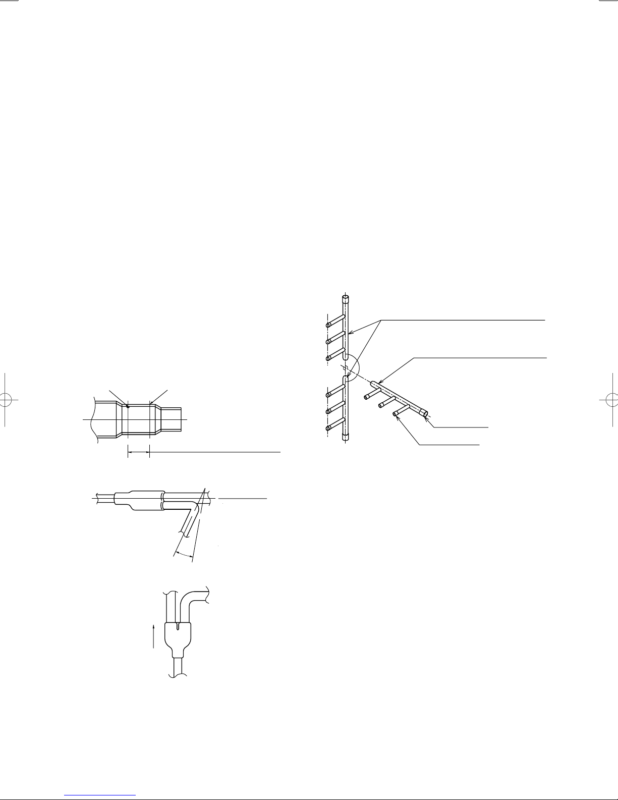
1-8. Installing Distribution Joint Kit (for Triple)
(NRF-DL28R)
● Check the system combination before installing the
distribution joints.
● Three indoor units must be installed within the same room.
● Use the supplied tube connectors to adjust the tube sizes of
the distribution joints.
How to Install Distribution Joints
Use the supplied distribution joints to complete refrigerant
tubing work.
Install distribution joints so that the tubes are horizontal after the
branch point.
Orientation of distribution joints
Only the distribution joints are horizontal with
respect to the ground. The collective tubes are
vertical with respect to the ground.
The collective tube and distribution joint
are horizontal with respect to the ground.
Make this as long as possible.
Insertion length of the connecting tube.
Horizontal Installation
Indoor unit
Outdoor unit
Side
Side
15° to 30°
upward slant
Vertical installation (directed upward or downward)
Collective tube
Distribution joint
<Gas tube side>
Length requirement for strainer on main distribution tube
side
Attach a straight tube 500 mm or longer to the main tubing side
of the distribution joint (for both liquid and gas tubing).
Tubing insulation
Be sure to apply thermal insulation to both the liquid and gas
tubing.
Depending on the conditions inside the ceiling, condensation
may form on the insulation material. If high temperatures and
high humidity are expected to occur inside the ceiling, add
glass wool (16 – 20 kg/m
3
, with a thickness of 10 mm or more)
to the below insulation materials and apply sufficient thermal
insulation.
12

Only the distribution joints are horizontal with respect
to the ground. The collective tubes are vertical with
respect to the ground.
2. Selecting the Installation Site
2-1. Indoor Unit
The collective tube and distribution joint are
horizontal with respect to the ground.
Collective tube
<Liquid tube side>
Inclination
INCORRECT
Distribution joint insulation material (supplied)
• Use the supplied insulation material.
• The supplied insulation material include only a tape for
temporarily fastening.
• Use insulation material or other material to seal the
joining lines so that there are no gaps.
• Use vinyl tape or similar means to seal and fasten the
insulation materials in place.
Seal securely with vinyl tape (4 locations)
Refrigerant tubing (field supply)
Tubing insulation material
(field supply; thickness of more than 10 mm)
Tubing insulation material must be able to
withstand temperatures of at least 120°C.
Refrigerant tubing (field supply)
Distribution joint
Inclination
Be sure to install so that the tubes are
horizontal after the branch point.
More than 500mm
More than 500mm
CAUTION
When moving the unit during or after unpacking, make
●
sure to lift it by holding its lifting lugs. Do not exert
any pressure on other parts, especially the refrigerant
piping, drain piping and flange parts.
If you think the humidity inside the ceiling might exceed
●
30°C and RH 80%, reinforce the insulation on the unit
body. Use glass wool or polyethylene foam as insulation
so that it is no thicker than 10 mm and fits inside the
ceiling opening.
AVOID:
● areas where leakage of flammable gas may be expected.
● places where large amounts of oil mist exist.
● direct sunlight.
● locations near heat sources which may affect the
performance of the unit.
● locations where external air may enter the room directly.
This may cause “condensation” on the air discharge ports,
causing them to spray or drip water.
● locations where the remote controller will be splashed with
water or affected by dampness or humidity.
● installing the remote controller behind curtains or furniture.
● locations where high-frequency emissions are generated.
● places where blocks air passages.
● places where the false ceiling is not noticeably on an incline.
DO:
● select an appropriate position from which every corner of the
room can be uniformly cooled.
● select a location where the ceiling is strong enough to
support the weight of the unit.
● select a location where tubing and drain pipe have the
shortest run to the outdoor unit.
● allow room for operation and maintenance as well as
unrestricted airflow around the unit.
● install the unit within the maximum elevation difference
above or below the outdoor unit and within a total tubing
length (L) from the outdoor unit as detailed in Tables 1-5 and
1-7.
● allow room for mounting the remote controller about 1m off
the floor, in an area that is not in direct sunlight or in the flow
of cool air from the indoor unit.
● places where optimum air distribution can be ensured.
● places where sufficient clearance for maintenance and
service can be ensured. (See the next page.)
2-2. Outdoor Unit
AVOID:
● heat sources and exhaust fans, etc. (Fig. 2-4)
● damp, humid or uneven locations.
DO:
● choose a place as cool as possible.
● choose a place that is well ventilated and outside air
temperature does not exceed maximum 45°C constantly.
● allow enough room around the unit for air intake/exhaust and
possible maintenance. (Fig. 2-5)
● use lug bolts or equal to bolt down unit, reducing vibration
and noise.
● If cooling operation is to be used when the outdoor air
temperature is –5°C or below, install a duct on the outdoor
unit.
13

Ceiling-Mounted Type
*
Ceiling
Wall
min. 25 cm min. 25 cm
Font view
NOTE
The rear of the indoor unit can be installed flush against
the wall.
Air
discharge
min. 50 cm
Side view
Air intake
Max. 25 cm
Obstacle
Fig. 2-1
Concealed-Duct Type / 4-Way Semi-Concealed Type
1 m
1 m
1 m
1 m
1 m
Installation space
For 3, 4, 5 and 6 HP Outdoor Unit
Distance between obstructions and the unit air inlet and outlet
must be as shown below.
3
*2
Inlet side C
Outlet side
More than
100 cm
More than 1 cm
*4
More than 1 cm
*1
Fig. 2-5
(Obstruction above unit)
Air direction chamber
(field supply)
*1
B
A
Inlet side
More than 20 cm
(Obstruction on
inlet side)
(ground)
Fig. 2-6
NOTE
● Concerning inlet-side distance “C” (Fig. 2-5)
The minimum for distance “C” is 15 cm if there are no
obstructions on the outlet side (wall *1 side) and *2 or *4 is
not present. In all other cases, the minimum for distance “C”
is 20 cm.
● If the unit is installed with the outlet side facing wall *1, then
there must be no obstructions on 2 of the remaining 3 sides:
*2, *3, *4.
● If wall *1 is on the outlet side (Fig. 2-5), or if obstructions
are present on all 3 sides *2, *3, and *4 (Fig. 2-5), then the
minimum distance for “A” and “B” is 2 m (Fig. 2-6). Even if
there is no wall on the outlet side, a minimum of 100 cm is
required.
Fig. 2-2
Wall-Mounted Type
min.
15 cm
min. 15 cm
Front View
min.
15 cm
Fig. 2-3
Exhaust fan
Hot air
Heat source
Outdoor
unit
Fig. 2-4
14

In case of multiple installations
● Provide a solid base (concrete block, 10 × 40 cm beams or
equal), a minimum of 15 cm above ground level to reduce
humidity and protect the unit against possible water damage
and decreased service life. (Fig. 2-7)
● Use lug bolts or equal to bolt down unit, reducingvibration
and noise.
Air intake
Air
discharge
Anchor bolts
(4 pieces)
Air intake
Min. 15 cm
Fig. 2-7
2-3. Air Discharge Chamber for Top Discharge
Be sure to install the air discharge chamber in the field when:
● it is difficult to keep a space of min. 50 cm between the air
discharge outlet and an obstacle.
● the air discharge outlet is facing a sidewalk and discharged
hot air annoys passers-by. (Fig. 2-8)
2-5. Precautions for Installation in Heavy Snow Areas
(1) The platform should be higher than the max. snow depth.
(Fig. 2-9)
(2) The 2 anchoring feet of the outdoor unit should be used for
the platform, and the platform should be installed beneath
the air intake side of outdoor unit.
(3) The platform foundation must be firm and the unit must be
secured with anchor bolts.
(4) In case of installation on a roof subject to strong wind,
countermeasures must be taken to prevent the unit from
being blown over.
2-6. Dimensions of Snow / Wind-proof Ducting and
Refrigerant Tubing Space for Installation
Min. 100
300
Min. 100
Duct
300
Duct
Outdoor Unit
Unit: mm
Air discharge
Fig. 2-8
2-4. Installing the Unit in Heavy Snow Areas
In locations with strong wind, snow-proof ducting should
likewise be fitted and direct exposure to the wind should be
avoided as much as possible.
Countermeasures against snow and wind
■
In regions with snow and strong wind, the following problems
may occur when the outdoor unit is not provided with a platform
and snow-proof ducting:
a) The outdoor fan may not run and damage of the unit may be
caused.
b) There may be no airflow.
c) The tubing may freeze and burst.
d) The condenser pressure may drop because of strong wind,
and the indoor unit may freeze.
Air intake
Outdoor
Unit
Duct
About 1/2 of
the unit height
Duct
Higher than the maximum
snow depth
Air intake
Platform (foundation)
Example of Installation
Fig. 2-10
Fig. 2-11
Without snowproof ducting
(Low platform)
With snow-proof
ducting
(High platform)
In regions with significant snowfall, the outdoor unit should
be provided with a platform and snow-proof duct.
Fig. 2-9
15

3. How to Install the Indoor Unit
4-Way Air Discharge Semi-Concealed Type
■
(4WK Type)
3-1. Preparation for Ceiling Suspension
This unit uses a drain pump. Use a carpenter’s level to check
that the unit is level.
3-2. Mounting the Suspension Bolts
(1) Fix the suspension bolts securely to the ceiling using the
method shown in the diagrams (Figs. 3-1 and 3-2), by
attaching them to the ceiling support structure, or by any
other method that ensures that the unit will be securely and
safely suspended.
(2) Follow Fig. 3-2 and Table 3-1 to make the holes in the
ceiling.
Hole-in-anchor
Hole-in-plug
Suspension bolt (M10 or 3/8")
(field supply)
A (suspension bolt pitch)
Concrete
Insert
Fig. 3-1
B (suspension bolt pitch)
D (ceiling opening dimension)
(3) Determine the pitch of the suspension bolts using the
supplied full-scale installation diagram. The diagram
and table (Fig. 3-3 and Table 3-2) show the relationship
between the positions of the suspension fitting, the unit,
and the panel.
Refrigerant tubing joint
Drain outlet
(other side) (VP25)
Suspension lug
D
E
(narrow side)
Refrigerant tubing joint
(wide side)
B
A
Unit: mm
Fig. 3-3
Table 3-2
Type
Length
ABCDE
Unit: mm
12, 16, 18, 25 113 173 256 210 88
36, 48, 60 113 173 319 210 88
3-3. Placing the Unit Inside the Ceiling
(1) When placing the unit inside the ceiling, determine the
pitch of the suspension bolts using the supplied full-scale
installation diagram. (Fig. 3-4)
Tubing and wiring must be laid inside the ceiling when
suspending the unit. If the ceiling is already constructed,
lay the tubing and wiring into position for connection to the
unit before placing the unit inside the ceiling.
(2) The length of suspension bolts must be appropriate for a
distance between the bottom of the bolt and the bottom of
the unit of more than 15 mm. (Fig. 3-4)
C
35
C (ceiling opening dimension)
Unit: mm
Fig. 3-2
Table 3-1
Type
Length
ABCD
Unit: mm
12, 16, 18, 25, 36, 48, 60 788 723 885 885
Over 15 mm
Supplied bolt
Full-scale installation diagram
(printed on top of container box)
12 – 17 mm
Fig. 3-4
16

(3) Thread the 3 hexagonal nuts and 2 washers (field supply)
onto each of the 4 suspension bolts (Fig. 3-5). Use 1 nut
and 1 washer for the upper side, and 2 nuts and 1 washer
for the lower side, so that the unit will not fall off the
suspension lugs.
Suspension bolt
Nuts and washers
(use for upper and lower)
Double nut
Suspension lug
Notch
12 – 17 mm
Fig. 3-5
(4) Adjust so that the distance between the unit and the ceiling
bottom is 12 to 17 mm. Tighten the nuts on the upper side
and lower side of the suspension lug.
(5) Remove the protective polyethylene used to protect the fan
parts during transport.
3-4. Installing the Drain Piping
(1) Prepare a standard hard PVC pipe (O.D. 32 mm) for the
drain and use the supplied drain hose and hose band to
prevent water leaks.
The PVC pipe must be purchased separately. The unit’s
transparent drain port allows you to check drainage. (Fig.
3-6)
Hard PVC
socket VP-25
(Field supply)
Packing
(supplied)
Hard PVC pipe
VP-25
(Field supply)
PVC adhesive
Connection pipe
(drain port)
Align the hose
band with the end
of the pipe.
Hose band
Supplied
drain hose
● Align the hose bands with the end of the hose. Tighten
the hose band firmly. Make sure that the bead is not
covered by the hose band.
(Fig. 3-6)
(2) After checking the drainage, wrap the supplied packing
and drain pipe insulator around the pipe. (Fig. 3-7)
Drain insulator (supplied)
Vinyl clamps
Fig. 3-7
CAUTION
Tighten the hose clamps so their locking nuts face upward.
(Fig. 3-6)
NOTE
Make sure the drain pipe has a downward gradient (1/100 or
more) and that there are no water traps.
CAUTION
Do not install an air bleeder as this may cause water to spray
from the drain pipe outlet. (Fig. 3-8)
Air bleeder prohibited
Fig. 3-8
CAUTION
● If it is necessary to increase the height of the drain pipe,
the section directly after the connection port can be
raised a maximum of 64 cm. Do not raise it any higher
than 64 cm, as this could result in water leaks. (Fig. 3-9)
● Do not install the pipe with an upward gradient from the
connection port. This will cause the drain water to flow
backward and leak when the unit is not operating. (Fig.
3-10)
30 cm or less
(as short as possible)
64 cm or less
Upward gradient prohibited
Bead
CAUTION
Insert the drain pipe until it contacts the socket as shown
in Fig. 3-6, then secure it tightly with the hose band.
● Do not use adhesive when connecting the supplied
hose.
Reasons: 1. It may cause water to leak from the connection.
Since the connection is slippery just after the
adhesive has been applied, the pipe easily slips
off.
2. The pipe cannot be removed when maintenance
is needed.
● Do not bend the supplied drain hose 90° or more. The
hose may slip off.
Fig. 3-6
Fig. 3-9 Fig. 3-10
● Do not apply force to the piping on the unit side when
connecting the drain pipe. The pipe should not be
allowed to hang unsupported from its connection to the
unit. Fasten the pipe to a wall, frame, or other support as
close to the unit as possible. (Fig. 3-11)
Support pieces
Fig. 3-11
● Provide insulation for any pipes that are run indoors.
NOTE
Refer to the Section “■ SUPPLEMENT ON DRAIN PIPING”.
17

3-5. Checking the Drainage
After wiring and drain piping are completed, use the following
procedure to check that the water will drain smoothly. For this,
prepare a bucket and wiping cloth to catch and wipe up spilled
water.
(1) Connect power to the power terminal board (R, S
terminals) inside the electrical component box.
(2) Slowly pour about 1,200 cc of water into the drain pan to
check drainage. (Fig. 3-12)
Drainage check
NOTE
Tubing can be extended in 4 directions. Select the direction
which will provide the shortest run to the outdoor unit. (Fig. 3-14)
Left-rear tubing
Left tubing
Rightrear tubing
(recommended)
Right tubing
Fig. 3-14
Over 100 mm
Drain pan outlet
Plastic container
for water intake
Water (Approx. 1,200 cc)
Fig. 3-12
(3) Short the check pin (CHK) on the indoor control board and
operate the drain pump. Check the water flow through the
transparent drain pipe and see if there is any leakage.
(4) When the check of drainage is complete, open the check
pin (CHK) and remount the tube cover.
CAUTION
Be careful since the fan will start when you short the pin on
the indoor control board.
Wall-Mounted Type (HW Type)
■
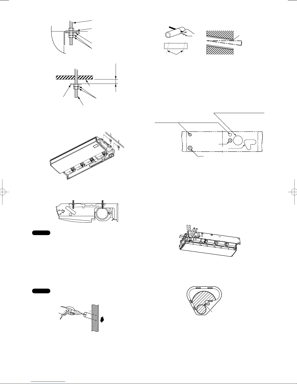
3-6. Removing the Rear Panel from the Unit
(1) Remove the set screws used to fasten the rear panel to the
indoor unit during transportation.
(2) Press up on the rear panel at the 2 locations shown by the
arrows and remove the rear panel (Fig. 3-13).
3-7. Selecting and Making a Hole
(1) Remove the rear panel from the indoor unit and place it
on the wall at the location selected. Fix the rear panel and
hook the unit onto the wall temporarily. Make sure the unit
is horizontal using a carpenter’s level or tape measure to
measure down from the ceiling.
(2) Determine which notch of the rear panel should be used.
(Fig. 3-15)
Center of left
rear tubing hole
Tubing hole diameter ø80
(3) Before drilling a hole, check that there are no studs or
pipes behind the determined location.
The above precautions are also applicable if tubing goes
through the wall in any other location.
(4) Using a sabre saw, key hole saw or hole-cutting drill
attachment, make a hole (dia. 80 mm) in the wall. (Fig. 3-16)
Indoor
side
Center of right
rear tubing hole
Outdoor
side
Fig. 3-15
Screws used during
transportation
Press
Remove the rear panel
Fig. 3-16
Fig. 3-13
18

(5) Measure the thickness of the wall from the inside edge to
the outside edge and cut the PVC pipe at a slight angle 6
mm shorter than the thickness of the wall. (Fig. 3-17)
CAUTION
Avoid areas where electrical wiring or conduits are located.
PVC pipe (locally purchased)
Cut at slight angle
Fig. 3-17
b) If the Wall is Brick, Concrete or Similar
Drill 4.8 mm dia. holes in the wall. Insert Rawl plugs for
appropriate mounting screws. (Fig. 3-21)
4.8 mm
dia. hole
Rawl plug
Fig. 3-21
(6) Place the plastic cover over the end of the pipe (for indoor
side only) and insert in the wall. (Fig. 3-18)
INSIDE OUTSIDE
Plastic
cover
Wall
PVC pipe
Sight
angle
Fig. 3-18
NOTE
The hole should be made at a slight downward gradient to the
outside.
3-8. Attaching the Rear Panel onto the Wall
Confirm that the wall is strong enough to support the unit.
See either Item a) or b) below depending on the wall type.
a) If the Wall is Wooden
(1) Attach the rear panel to the wall with the 10 screws
provided. (Fig. 3-19)
If you are not able to line up the holes in the rear panel
with the beam locations marked on the wall, use Rawl
plugs or toggle bolts to go through the holes on the panel
or drill 5 mm dia. holes in the panel over the stud locations
and then mount the rear panel.
3-9. Removing the Grille to Install the Indoor Unit
In principle, with this model wiring can be completed without
removing the grille.
However, if it is necessary to change the settings on the PCB,
follow the procedure below.
Removing the grille
(1) Lift up on both sides of the air-intake grille to open. (Fig.
3-22)
(2) Remove the filter. (Fig. 3-22)
Intake grille
Filter
Flap
(3) Adjust the flap so that it is horizontal. (Fig. 3-23)
(4) Open the installation screw covers below the grille (3
locations). (Fig. 3-23)
(5) Remove the screws. (Fig. 3-23)
Open the grille
Fig. 3-22
(2) Check with a tape measure or carpenter’s level. This is
important so that the unit is correctly installed. (Fig. 3-20)
(3) Make sure the panel is flush against the wall. Any space
between the wall and unit will cause noise and vibration.
Fig. 3-19
Fig. 3-20
(6) Remove the grille. (Fig. 3-24)
Remove the grille
19
Installation screw
cover
Fig. 3-23
Fig. 3-24

Attaching the grille
(1) Close the flap.
(2) Keep the grille installation tabs aligned with the top portion
of the grille, and reinstall the lower portion of the grille.
Fit the installation tabs into the grooves and press the
lower portion of the grille back into its original position.
(3) Press on the installation tabs to completely close the grille.
Check that the grille and frame are fitted tightly together.
3-10. Preparing the Tubing
(1) Arrangement of tubing by directions
a) Right or left tubing
The corner of the right or left frame should be cut with a
hacksaw or similar. (Fig. 3-25)
Frame
Right tubing
outlet
Raising the clamp to lift up the indoor unit will facilitate this
work. (Fig. 3-28)
Clamp
Fig. 3-28
To remove the indoor unit, press up on the 2 locations
marks) on the lower part of the unit frame to disconnect
(
from the attachment tabs. Refer to Section 3-6. “Removing
the Rear Panel from the Unit” (Fig. 3-13).
Then lift up the indoor unit to remove.
When left or right side tubing
Fig. 3-25
b) Right-rear or left-rear tubing
In this case, the corners of the frame do not need to be
cut.
(2) Be sure to insulate the part of the drain hose that is run
indoors, and the refrigerant tubing.
If these are not insulated, condensation may result in
dripping and damage to walls and furniture.
The flare nuts on the 25-type (only) are large; therefore,
use the supplied insulation material.
(3) To mount the indoor unit on the rear panel.
1. When attaching the indoor unit, position the indoor unit
onto the attachment tabs on the upper part of the rear
panel. (Fig. 3-26)
Attachment tabs
Attachment tabs
Fig. 3-26
2. Press on the air outlet to hold it in place, and press
the lower part of the indoor unit until a “click” sound is
heard and the indoor unit is securely fastened to the
attachment tabs on the lower side of the rear panel. (Fig.
3-27)
3-11. Shaping the Tubing
Right-rear tubing
(1) Shape the refrigerant tubing so that it can easily go
through the hole. (Fig. 3-29)
Attachment tab
Insulating
tape
Plastic cover
(2) After performing a leak test, wrap both the refrigerant
tubing and drain hose together with insulating tape.
The drain hose should be positioned below the refrigerant
tubes, and should be given sufficient space so that no
strong pressure is applied to it.
(3) Push the wiring, refrigerant tubing and drain hose through
the hole in the wall. Adjust the indoor unit so it is securely
mounted on the rear panel.
Left or left-rear tubing
(1) Pass the tubing and drain hose into the rear of the indoor
unit. Provide sufficient length for the connections to be
made (Fig. 3-30).
Next, bend the tubing with a pipe bender, and connect
them.
Refrigerant
tubing
Indoor and outdoor
unit connection
wiring
Fig. 3-29
Press
Insulation
Fig. 3-30
Fig. 3-27
20

(2) After performing a leak test, wrap the refrigerant tubing and
drain hose together with insulating tape (Fig. 3-31).
Refrigerant tubing
Insulating tape
Drain hose
Rear panel
Inter-unit wiring
Fig. 3-31
Then fit the tubing into the tubing storage space in the rear
of the indoor unit and clamp in place.
(3) Adjust the indoor unit so that it is securely mounted on the
rear panel.
3-12. Installing the Drain Hose
a) The drain hose should be slanted downward to the outside.
(Fig. 3-32)
Indoor unit
Slant
Refrigerant
tubing
Fig. 3-32
b) Never allow water traps to be formed in the course of the
hose.
c) If the drain hose will run in the room, insulate* the hose so
that chilled condensation will not damage furniture or floors.
* Foamed polyethylene or its equivalent is recommended.
WARNING
Do not supply power to the unit or operate it until all tubing
and wiring to the outdoor unit are completed.
21

Ceiling-Mounted Type (C Type)
■
B
C
3-13. Required Minimum Space for Installation and
170
Service
(1) Dimensions of suspension bolt pitch and unit
Typ e
Length
ABC
320
bolt pitch)
(Suspension
12, 16, 18 855 910 210
25 1125 1180 210
36, 48, 60 1540 1595 210
27.5
Unit: mm
(2) Refrigerant tubing • drain hose position
Rear (Figure shows view from front)Left side
Liquid
171
251 84 146 161
Closed with rubber stopper at time of shipment.
39
Left drain position
tubing
Gas tubing
Right drain position
75 97 216
Ceiling side
(Suspension bolt pitch)
A
105
171
39
680
27.5
Unit: mm
Right side
Air intake
Air
Fig. 3-33
(Liquid tubing •
Gas tubing)
251
Unit: mm
Fig. 3-34
(3) Unit opening position (Refrigerant tubing • drain hose • power inlet port • remote controller wiring inlet port)
Left-side drain hose
outlet port
*3
Remote controller
wiring inlet port
(ø30, knock-out)
*1
Side panel
*3
Remote controller wiring
inlet port
(ø30, rubber grommet on
right side only)
123
53
Knock-out
Outside air intake duct connection port
(ø100, knock-out)
32
171
32
Power inlet port
(ø40, knock-out)
84
Left-side drain
hose outlet port
60
Rear tubing hole
Top outlet port
Power inlet port
(ø40, knock-out)
Rear outlet port
90
347
110 76
262
125 72
216
*2
Unit: mm
70
*1 Use a compass saw, jig saw or similar tool
*2 If the optional drain up kit is installed, this
*3 If the remote controller wiring inlet port is
85106
Right-side drain
50130
hose outlet port
Side panel
and cut along the indented portion of the side
panel.
becomes the upper tubing outlet port.
For details, refer to the manual for the
optional part.
changed to the left side or the left top side,
relocate the rubber grommet to the left side.
Use aluminum tape or similar material to seal
the unused inlet port on the right side.
Position of plate
inside side panel
*1
Fig. 3-35
22

(4) Wall and ceiling side opening position
Figure shows view from front.
145
ø100 wall
ø100 wall side
90
opening (for leftside drain hose)
Figure shows view from top.
side opening
135
Ceiling
WARNING
It is important that you use extreme care in supporting
the indoor unit from the ceiling. Ensure that the ceiling is
strong enough to support the weight of the unit. Before
hanging the ceiling unit, test the strength of each attached
suspension bolt.
(4) Screw in the suspension bolts, allowing them to protrude
from the ceiling (Figs. 3-38 and 3-39). The distance of
each exposed bolt must be of equal length within 50 mm.
(Fig. 3-40)
Wall
ø100 ceiling
opening
ø100 ceiling
opening
125
90
*
155
Unit: mm
* If the optional drain up kit is installed, create a ø100 hole
along the dotted line (part marked with * in fi gure).
Fig. 3-36
3-14. Suspending the Indoor Unit
(1) Place the full-scale diagram (supplied) on the ceiling at the
location where you want to install the indoor unit. Use a
pencil to mark the drill holes (Fig. 3-37).
Ceiling
Full-scale installation
diagram
NOTE
Since the diagram is made of paper, it may shrink or stretch
slightly because of high temperature or humidity. For this
reason, before drilling the holes maintain the correct dimensions
between the markings.
(2) Drill holes at the 4 points indicated on the full-scale
diagram.
(3) Depending on the ceiling type:
a) Insert suspension bolts (Fig. 3-38).
or
b) Use existing ceiling supports or construct a suitable
support (Fig. 3-39).
Hole-in-anchor
Hole-in-plug
Suspension bolt (M10 or 3/8")
(field supply)
A
Concrete
Ceiling tiles
Ceiling support
A
Wall
Fig. 3-37
Insert
Fig. 3-38
Unit
Ceiling
surface
Fixture
Within
50 mm
Fig. 3-40
(5) Before suspending the indoor unit, remove the 2 or 3
screws on the latch of the air-intake grilles, open the
grilles, and remove them by pushing the claws of the
hinges (Fig. 3-41). Then remove both side panels sliding
them along the unit toward the front after removing the 2
attachment screws. (Fig. 3-42)
Pull out the air-intake grille
pushing claws of the hinges
Screw
Latch
Slide
Air-intake grille
Hinge
Fig. 3-41
Slide toward
front side
Side panel
Fig. 3-42
(6) Carry out the preparation for suspending the indoor unit.
The suspension method varies depending on whether
there is a suspended ceiling or not. (Figs. 3-43 and 3-44)
(7) Suspend the indoor unit as follows:
a) Mount 1 washer and 2 hexagonal nuts on each
suspension bolt (Fig. 3-45).
Suspension bolt
(field supply)
Unit
Fixture
Ceiling surface
Washer (supplied)
Double nut
(field supply)
Fig. 3-43
Fig. 3-39
23
Suspension bolt
(field supply)
Washer
(field supply)
Unit
Washer (supplied)
Double nut
(field supply)
Fig. 3-44
Approx.
25 mm
Ceiling
surface
Washer
(supplied)
Suspension bolt
Nut
(field supply)
Fig. 3-45
b) Lift the indoor unit, and place it on the washers through
the notches, in order to fix it in place. (Fig. 3-46)
PVC pipe (locally purchased)
INSIDE
Cut at slight angle
Wall
OUTSIDE
PVC pipe
Slight
angle
Fig. 3-49
3-15. Duct for Fresh Air
There is a duct connection port (knock-out hole) at the right-rear
of the top panel of the indoor unit for drawing in fresh air. If it
is necessary to draw in fresh air, remove the cover by opening
the hole and connecting the duct to the indoor unit through the
connection port. (Fig. 3-50)
Outside air intake duct connection
port (ø100, knock-out)
Remote controller wiring inlet port
(ø30, rubber grommet on right side only)
Power inlet port
(ø40, knock-out)
Rear outlet port
Left-side drain
hose outlet port
Unit: mm
Fig. 3-50
Fig. 3-46
c) Tighten the 2 hexagonal nuts on each suspension bolt to
suspend the indoor unit as shown in Fig. 3-47.
Fig. 3-47
NOTE
The ceiling surface is not always level. Confirm that the indoor
unit is evenly suspended. For the installation to be correct,
leave a clearance of about 10 mm between the ceiling panel
and the ceiling surface and fill the gap with an appropriate
insulation or filler material.
(8) If the tubing and wiring are to go towards the rear of the
unit, make holes in the wall. (Fig. 3-48)
(9) Measure the thickness of the wall from the inside to the
outside and cut PVC pipe at a slight angle to fit. Insert the
PVC pipe in the wall. (Fig. 3-49)
NOTE
The hole should be made at a slight downward slant to the
outside.
Indoor
side
Outdoor
side
3-16. Shaping the Tubing
● The positions of the refrigerant tubing connections are
shown in the figure below. (The tubing can be routed in 3
directions.) (Fig. 3-51)
* When routing the tubing out through the top or right sides,
knock out the appropriate parts in the top panel and cut
notches in the side panel (Fig. 3-50).
* When routing the tubing out through the top, the optional L-
shape tubing kit is required.
Fig. 3-51
If the tubing is to be routed out together, use a box cutter or
similar tool to cut out the part of the rear cover indicated by
the marked area (Fig. 3-52), to match the positions of the
tubes. Then draw out the tubing.
Rear cover
Fig. 3-52
Fig. 3-48
24

3-17. Installing the Drain Pipe
● Prepare standard PVC pipe for the drain and connect it to
the indoor unit drain pipe with the supplied hose clamps to
prevent water leaks.
(1) Drain hose connection
● The drain hose is connected below the refrigerant tubing.
(2) Installing the drain hose
● To install the drain hose, first place 1 of the 2 hose bands
over the unit drain port and the other hose band over the
hard PVC pipe (not supplied). Then connect both ends of the
supplied drain hose.
● On the unit drain side, grasp the hose band with pliers and
insert the drain hose all the way to the base.
CAUTION
● Attach so that the hose band fastener is on the side of
the drain port. (Fig. 3-54)
● Attach the hose bands so that each is approximately
5 to 25 mm from the end of the supplied drain hose.
● If other commercially available hose bands are used, the
drain hose may become pinched or wrinkled and there
is danger of water leakage. Therefore be sure to use the
supplied hose bands. When sliding the hose bands, be
careful to avoid scratching the drain hose.
● Do not use adhesive tape when connecting the supplied
drain hose to the drain port (either on the main unit or the
PVC pipe).
● Wrap the hose with the supplied drain hose insulation and
use the 4 twist ties so that the hose is insulated with no
gaps.
● Connect the drain pipe so that it slopes downward from the
unit to the outside. (Fig. 3-53)
Min.
1/100
Good
Not good
Fig. 3-53
● Never allow water traps to occur in the course of the piping.
● Insulate any piping inside the room to prevent dripping.
● After the drain piping, pour water into the drain pan to check
that the water drains smoothly.
● If the drain hose is to be raised, use the optional drain up kit.
The drain hose can be raised 60 cm above the top of the
main unit. (For details, refer to the manual for the optional
part.)
* If the drain hose is routed through the left side, refer to Fig.
3-51, and follow the procedure above to install the hose.
Reattach the rubber stopper removed earlier onto the right
side.
The rubber stopper can be inserted easily by using a
screwdriver or similar tool to press the stopper into the drain
port on the main unit. Press the stopper into the main unit
drain port as far as it will go.
Drain port
Screwdriver
CAUTION
Check local electrical codes and regulations before wiring.
Also, check any specified instruction or limitations.
Twist tie
(4 ties)
Unit drain port
25 25
Unit drain pan
Drain hose
insulation
(supplied)
5
140
Hard PVC pipe
(equivalent to
VP-20)
(Field supply)
5
Position to
fasten hose
bands
Drain hose
(supplied)
Hose band
(2 bands, supplied)
Unit: mm
Fig. 3-54
How to carry out power supply wiring
(1) Wiring connection ports
The power inlet ports are located at the rear and top.
The remote controller wiring inlet ports are located at the rear
and top (for use with the wired remote controller). For details,
refer to Fig. 3-50. For the method used to insert the wiring, refer
to Fig. 3-55.
CAUTION
When removing the fastening bracket from the cover of the
electrical component box, use caution to avoid dropping
the bracket.
(2) How to carry out wiring
● Open the knock-out hole on the rear or top of the main unit.
Attach the supplied rubber grommet and pull the power
wiring into the main unit.
● Feed the wiring into the wiring inlet port on the electrical
component box. Connect the wiring to the terminal plate and
fasten in place with the supplied clamp.
● Perform electrical and grounding work in accordance with
the package A/C power specifications, and following local
electrical codes and regulations.
Remote controller wiring inlet port
* Insert the remote controller wiring into
the electrical component box from the
inlet port as shown in the figure. This is
done regardless of whether the wiring
was inserted from the top, rear, or left
side of the main unit.
Rubber stopper
25
Clamp
Power, inter-unit wiring
Power, inter-unit wiring, remote
controller wiring inlet port
Fig. 3-55

9
10
11
M-ø3.3
4-ø12
L-ø6
I
10
10
10
5555 200
10
IJJK
B
C
D (150)
40
EEEF75
65
285
70 130
25 210
310
25
175
35
90
3131
25
100
185
58025
115
190
85
25
70 30
160
630 25
10
88
275
260
1919
Concealed-Duct Type (D Type)
■
3-18. Required Minimum Space for Installation and
Service
● This air conditioner is usually installed above the ceiling so
that the indoor unit and ducts are not visible. Only the air
intake and air outlet ports are visible from the unit bottom.
● The minimum space for installation and service is shown in
Fig. 3-56 and Table 3-3.
Table 3-3
Type 12, 16, 18 25 36, 48, 60
A (Length) 780 1,080 1,560
Number of
duct flanges
234
● It is recommended that space be provided (450 × 450 mm)
for checking and servicing the electrical system.
● The detailed dimensions of the indoor unit is shown in Fig.
3-57 and Table 3-4.
Unit: mm
A (Suspension bolt pitch)
Min. 250
or more
580
Air outlet duct flange
Indoor unit
Min.
250ormore
Min.
400
or
more
Electrical
component box
Inspection
access
450 × 450
Refrigerant
tubing
Min. 650 or more
Unit: mm
Fig. 3-56
Table 3-4
Type
36, 48, 60 1,442
12, 16, 18 662
25 962
(Suspension bolt pitch)
(Suspension bolt pitch)
Inspection access panel
(Field supply)
(450
×
450)
access
(Ceiling opening dimension)
(Hole)
Inspection
(Option or field supply)
G (Ceiling opening dimension)
H (Duct suspension bolt pitch)
(Hole)
10
11
8
9
Flange for flexible air outlet duct (ø200)
Tube cover
Electrical component box
Flange for air intake duct
A (O.D)
(Hole)
A (O.D)
1
2
3
4
5
7
Suspension lug6 Power supply outlet (2-ø30)
Fresh air intake port (ø150)
Refrigerant tubing joint (liquid tube)
Refrigerant tubing joint (gas tube)
Upper drain port (O.D. 32 mm)
Bottom drain port (O.D. 26 mm)
(180 × 5)
(230 × 6)
1,380
1,480 1,560 335 310 1,460 1,495 130
900
1,000 1,080 290 272 980 1,015 130
Dimension
ABCDEFGHI JK
(200 × 3)
600
700 780 290 262 680 715 180 – 340 8 12
Ceiling
Unit: mm
26
Fig. 3-57
(245 × 1)
(245 × 2)
490
240 16 18
250 12 16
245
No. of holes
LM
Unit: mm

3-19. Suspending the Indoor Unit
Depending on the ceiling type:
• Insert suspension bolts (Fig. 3-58)
or
• Use existing ceiling supports or construct a suitable
support (Fig. 3-59).
Hole-in-anchor
Hole-in-plug
Concrete
Suspension bolt (M10 or 3/8")
(field supply)
Ceiling support
Insert
Fig. 3-58
Ceiling tiles
Fig. 3-59
Suspension bolt
Hexagonal nut
Double nuts
● This shows an example of installation.
Air outlet duct
Air-outlet grille
Ceiling material
Indoor unit
Fig. 3-61
Bolt anchor
Suspension
bolt
Air-intake
duct
Air-intake
grille
Fig. 3-62
WARNING
It is important that you use extreme care in supporting
the indoor unit inside the ceiling. Ensure that the ceiling
is strong enough to support the weight of the unit. Before
hanging the unit, test the strength of each attached
suspension bolt.
(1) When placing the unit inside the ceiling, determine the
pitch of the suspension bolts referring to the dimensional
data as shown in Fig. 3-56 and Table 3-4.
Tubing must be laid and connected inside the ceiling when
suspending the unit. If the ceiling is already constructed,
lay the tubing into position for connection to the unit before
placing the unit inside the ceiling.
(2) Screw in the suspension bolts allowing them to protrude
from the ceiling (Fig. 3-58). (Cut the ceiling material, if
necessary.)
(3) Thread the 3 hexagonal nuts and 2 washers (field supply)
onto each of the 4 suspension bolts (Figs. 3-60 and 3-61).
Use 1 nut and 1 washer for the upper part, and 2 nuts and
1 washer for the lower part, so that the unit will not fall off
the suspension lugs.
Suspension bolt
Nuts and washers
(use for upper and lower)
Suspension lug
Double nuts
Notch
Fig. 3-60
27

3-20. Installing the Drain Pipe
(1) Prepare standard hard PVC pipe (O.D. 32 mm) for the
drain and use the supplied hose band to prevent water
leaks.
The PVC pipe must be purchased separately.
The transparent drain part on the unit allows you to check
drainage. (Fig. 3-63)
CAUTION
Do not use adhesive tape at the drain connection port on
●
the indoor unit.
Insert the drain pipe until it contacts the socket, and then
●
secure it tightly with the hose band.
Do not use the supplied drain hose bent at a 90° angle.
●
(The maximum permissible bend is 45°.)
Tighten the hose clamps so their locking nuts face
●
upward. (Fig. 3-63)
30 cm or less
50 cm or less
Good
Fig. 3-65-2
● Do not install the pipe with an upward gradient from the
connection port. This will cause the drain water to flow
backward and leak when the unit is not operating.
(Fig. 3-65-3)
Upward gradient
Prohibited
Align the hose band with end of the hose, and
tighten so that it does not contact the bead.
Drainage check
section on drain port
(transparent)
Drain hose
(supplied)
Bead
Hard PVC
socket
VP-25 (not
supplied)
Packing
(supplied)
Hard PVC
pipe VP-25
(not supplied)
PVC
adhesive
Fig. 3-63
(2) After connecting the drain pipe securely, wrap the supplied
packing and drain pipe insulator around the pipe, then
secure it with the supplied vinyl clamps. (Fig. 3-64)
Drain insulator (supplied)
Vinyl clamps
Fig. 3-64
NOTE
Make sure the drain pipe has a downward gradient (1/100 or
more) and that there are no water traps.
Fig. 3-65-3
● Do not apply force to the piping on the unit side when
connecting the drain pipe. The pipe should not be allowed to
hang unsupported from its connection to the unit. Fasten the
pipe to a wall, frame, or other support as close to the unit as
possible. (Fig. 3-65-4)
Support pieces
Fig. 3-65-4
NOTE
Refer to the Section “■ SUPPLEMENT ON DRAIN PIPING”.
CAUTION
● Do not install an air bleeder as this may cause water to
spray from the drain pipe outlet. (Fig. 3-65-1)
Air bleeder
Prohibited
● If it is necessary to increase the height of the drain pipe, the
section directly after the connection port can be raised a
maximum of 50 cm. Do not raise it any higher than 50 cm,
as this could result in water leaks. (Fig. 3-65-2)
Fig. 3-65-1
28

3-21. Checking the Drainage
After wiring and drain piping are completed, use the following
procedure to check that the water will drain smoothly. For this,
prepare a bucket and wiping cloth to catch and wipe up spilled
water.
(1) Connect power to the power terminal board (R, S
terminals) inside the electrical component box.
(2) Remove the tube cover and slowly pour about 1,200 cc
of water through the opening into the drain pan to check
drainage.
(3) Short-circuit the check pin (CHK) on the indoor control
circuit board and operate the drain pump. Check the water
flow through the transparent drain port and see if there is
any leakage.
CAUTION
Be careful since the fan will start when you short the pin on
the indoor control board.
(4) When the drainage check is complete, open the check pin
(CHK) and remount the insulator and drain cap onto the
drain inspection port.
Water intake
Fig. 3-66
Indoor Fan Performance
12 Type 16, 18 Type
(Pa)
100
Limit line
Limit line
50
External Static Pressure
0
5
AirFlow (m3/minute)
25 Type 36 Type
150
(Pa)
Limit line
100
Limit line
50
External Static Pressure
L
0
10
AirFlow (m3/minute)
48 Type
HT
H
M
L
10
HT
H
M
20
15150
(Pa)
(mmAq)
10
100
Limit line
5
0
15
(mmAq)
10
5
0
Limit line
50
External Static Pressure
0
AirFlow (m3/minute)
150
Limit line
(Pa)
100
Limit line
50
External Static Pressure
0
20
AirFlow (m3/minute)
L
10
L
60 Type
15150
(mmAq)
10
5
HT
H
M
0
15
15
(mmAq)
HT
10
H
M
5
0
30
3-22. Increasing the Fan Speed
If external static pressure is too great (due to long extension
of ducts, for example), the airflow volume may drop too low at
each air outlet. This problem may be solved by increasing the
fan speed using the following procedure:
(1) Remove 4 screws on the electrical component box and
remove the cover plate.
(2) Disconnect the fan motor sockets in the box.
(3) Take out the booster cable (sockets at both ends) clamped
in the box.
(4) Securely connect the booster cable sockets between the
disconnected fan motor sockets in step 2 (Fig. 3-67).
Electrical component box
Fan
motor
(5) Place the cable neatly in the box and reinstall the cover
Booster cable
Booster cable
Fan motor socket
(At shipment) (Booster cable installed)
Fig. 3-67
plate.
Limit line
15
150
Limit line
(Pa)
100
Limit line
50
External Static Pressure
L
0
20
AirFlow (m3/minute)
NOTE
30 40 18 22 26 30 34 38 42
HT : Using the booster cable
HT
H
M
150
(Pa)
(mmAq)
10
5
0
Limit line
100
External Static Pressure
50
L
0
AirFlow (m3/minute)
HT
H
M
H : At shipment
Fig. 3-68
How to read the diagram
■
The vertical axis is the external static pressure (Pa) while
the horizontal axis represents the airflow (m
3
/minute). The
characteristic curves for “HT”, “H”, “M” and “L” fan speed control
are shown. The nameplate values are shown based on the
“H” airflow. For the 25 type, the airflow is 18 m
3
/minute, while
the external static pressure is 49 Pa at “H” position. If external
static pressure is too great (due to long extension of ducts,
for example), the airflow volume may drop too low at each air
outlet. This problem may be solved by increasing the fan speed
as explained above.
15
(mmAq)
10
5
0
29

3-23. When Installing the Indoor Unit
Confirm that the indoor unit should be installed in a horizontal position.
Use the level gauge or vinyl tube and check every four corner of the
unit is in horizontal.
If the air outlet duct flange is positioned with downward gradient,
there is in danger of water splash or drainage.
Also, dust may sometimes be contaminated inside the drain pan caused
by the residual drain water.
Install the air outlet duct flange side in horizontal or upward and within the
range of 10mm in the upward direction.
Never install it with a downward gradient against horizontal.
Air outlet duct flange
Air outlet duct flange
(Prohibited)
(Prohibited)
(Prohibited)
(Prohibited)
Level gauge
Level gauge
Make sure to confirm
Make sure to confirm
that the unit is in horizontal
that the unit is in horizontal
at the position of the
at the position of the
ceiling-mount hanger by
ceiling-mount hanger by
using a level gauge
using a level gauge
or vinyl tubing.
or vinyl tubing.
Fig. 3-69
3-24. Required Minimum Space for Installation and Service
If the ceiling tiles cannot be removed, provide the opening holes on the
lower side of the indoor unit for removing the unit in order to maintain
and clean the drain pan and heat exchanger or provide a minimum of
300mm or more space.
Fig. 3-70
Min. 300mm or more spaceMin. 300mm or more space
30

SUPPLEMENT ON DRAIN PIPING
■
1. Drain hose installation
Drain port
Drain port
(Drainage check section
(Drainage check section
on drain port, transparent,
on drain port, transparent,
ABS resin)
ABS resin)
Indoor unit
Indoor unit
Hose band
Hose band
(supplied)
(supplied)
Soft polyvinyle chloride socket
Soft polyvinyle chloride socket
Bead
Bead
Drain hose
Drain hose
(supplied)
(supplied)
Hard PVC socket (VP25)
Hard PVC socket (VP25)
Hard PVC pipe
Hard PVC pipe
(VP25 field supplied)
(VP25 field supplied)
Do not use adhesive here.
Do not use adhesive here.
Drain port may possibly be damaged
* Apply approx. 2g of the adhesive on both sides of the
Drain port may possibly be damaged
* Apply approx. 2g of the adhesive on both sides of the
if polyvinyle chloride adhesive is used.
if polyvinyle chloride adhesive is used.
Align the hose band with end of the hose and
Align the hose band with end of the hose and
tighten so that it does not contact the bead.
tighten so that it does not contact the bead.
(Torque 2.5 - 3.4N.m)
(Torque 2.5 - 3.4N.m)
5mm
Indoor unit
Indoor unit
5mm
Bead
Bead
20mm or more
20mm or more
*
*
Packing (supplied)
Packing (supplied)
Adhere with polyvinyle chloride adhesive.
Adhere with polyvinyle chloride adhesive.
supplied drain hose with a joint socket and hard PVC pipe.
supplied drain hose with a joint socket and hard PVC pipe.
Wipe off the protrusion-adhesive with a soft cloth.
Wipe off the protrusion-adhesive with a soft cloth.
Note:
Note:
Be sure to tightly insert the hard
Be sure to tightly insert the hard
PVC pipe joint (including elbow)
PVC pipe joint (including elbow)
minimum 20mm or more.
minimum 20mm or more.
However, do not use the hard
*
However, do not use the hard
*
PVC pipe joint allowable more
PVC pipe joint allowable more
than 55mm insertion.
than 55mm insertion.
57mm
57mm
Drain insulator (supplied)
Drain insulator (supplied)
* After checking the drainage, wrap the supplied packing and drain pipe insulator around the pipe.
NOTE
There is possibility to cause water leakage unless the above steps are carried out.
2. Checkpoint after installation
After installation of indoor and outdoor units, panels and electrical wiring, check the following items.
Checkpoint Symptom Check Remark
1 Are indoor and outdoor units correctly installed? Fall, vibration, noise
2 Is gas leakage tested? No cooling, no heating
Is insulation completed?
3
(Refrigerant piping and drain piping)
water leakage
4 Is drain water running smoothly? water leakage
5 Does the power voltage meet the nameplate? Inoperative, burnout
6 Is there miswiring or incorrect connection? Inoperative, burnout
7 Is the ground construction completed? Ground leakage
Is the wire gauge followed by the recommended
8
specifications?
Are the air intake and air outlet of the indoor and
9
outdoor units sealed by any obstacles?
Inoperative, burnout
No cooling, no heating
31

4. HOW TO INSTALL THE OUTDOOR UNIT
4-1. Installing the Outdoor Unit
● Use concrete or a similar material to make the base, and
ensure good drainage.
● Ordinarily, ensure a base height of 5 cm or more. If a drain
pipe is used, or for use in cold-weather regions, ensure a
height of 15 cm or more at the feet on both sides of the unit.
(In this case, leave clearance below the unit for the drain
pipe, and to prevent freezing of drainage water in coldweather regions.)
● Refer to Fig. 4-1 for the anchor bolt dimensions.
● Be sure to anchor the feet with anchor bolts (M10). In
addition, use anchoring washers on the top side. (Use large
square 32 × 32 SUS washers with JIS nominal diameter of
10.) (Field supply)
For 3, 4, 5 and 6 HP unit
Drain port (2 locations)
171
219
660
150
111
1313
20
4-2. Drainage Work
Follow the procedure below to ensure adequate draining for the
outdoor unit.
● For the drain port dimensions, refer to Fig. 4-1.
● Ensure a base height of 15 cm or more at the feet on both
sides of the unit.
● When using a drain pipe, install the drain socket onto the
drain port. Seal the other drain port with the rubber cap.
4-3. Routing the Tubing and Wiring
● The tubing and wiring can be extended out in 4 directions:
front, rear, right, and down.
● The service valves are housed inside the unit. To access
them, remove the inspection panel. (To remove the
inspection panel, remove the 3 screws, then slide the panel
downward and pull it toward you.)
(1) If the routing direction is through the front, rear, or right,
use a nipper or similar tool to cut out the knockout holes for
the inter-unit control wiring outlet, power wiring outlet, and
tubing outlet from the appropriate covers A and B.
(2) If the routing direction is down, use a nipper or similar tool
to cut out the lower flange from cover A. (Fig. 4-2)
Inter-unit control wiring
outlet
Drain port
341
296
13 13
942
405
19
15 10380
Anchor bolt (M10)
Fig. 4-1
Inspection panel
Rear
Cover A
Front
Power wiring outlet
Down
Tubing outlet
Cover B
Right
Fig. 4-2
CAUTION
● Route the tubing so that it does not contact the
compressor, panel, or other parts inside the unit.
Increased noise will result if the tubing contacts these
parts.
● When routing the tubing, use a tube bender to bend the
tubes.
● In cold-weather regions, in order to prevent drainage
water from freezing, do not install the drain socket cap.
Also take steps to prevent water from accumulating
around the unit.
32

5. ELECTRICAL WIRING
5-1. General Precautions on Wiring
(1) Before wiring, confirm the rated voltage of the unit as
shown on its nameplate, then carry out the wiring closely
following the wiring diagram.
(2) Provide a power outlet to be used exclusively for each unit
and a circuit breaker for overcurrent protection should be
provided in the exclusive line.
(3) To prevent possible hazards from insulation failure, the unit
must be grounded.
(4) Each wiring connection must be done in accordance with
the wiring system diagram. Wrong wiring may cause the
unit to misoperate or become damaged.
(5) Do not allow wiring to touch the refrigerant tubing,
compressor, or any moving parts of the fan.
(6) Unauthorized changes in the internal wiring can be very
dangerous. The manufacturer will accept no responsibility
for any damage or misoperation that occurs as a result of
such unauthorized changes.
(7) Regulations on wire diameters differ from locality to
locality. For field wiring rules, please refer to your LOCAL
ELECTRICAL CODES before beginning.
You must ensure that installation complies with all relevant
rules and regulations.
(8) To prevent malfunction of the air conditioner caused by
electrical noise, care must be taken when wiring as follows:
● The remote control wiring and the inter-unit control wiring
should be wired apart from the inter-unit power wiring.
● Use shielded wires for inter-unit control wiring between units
and ground the shield on both sides.
(9) If the power supply cord of this appliance is damaged,
it must be replaced by a repair shop designated by the
manufacturer, because special-purpose tools are required.
Control wiring
(C) Inter-unit
(between outdoor
and indoor units)
control wiring
2
0.75 mm
Use shielded wiring*
(AWG #18)
Max. 1,000 m Max. 500 m Max. 200 m (Total)
(D) Remote control
wiring
0.75 mm2 (AWG #18)
Use shielded wiring
(E) Control wiring
for group control
0.75 mm2 (AWG #18)
Use shielded wiring
NOTE
*
With ring-type wire terminal.
5-2. Recommended Wire Length and Wire Diameter
for Power Supply System
Outdoor unit (Single-phase)
(A) Power supply Time delay
Wire size Max. length
OU-PSINV-25HR 4 mm
OU-PSINV-36HR 4 mm
OU-PSINV-48HR 6 mm
OU-PSINV-60H 6 mm
2
2
2
2
24 m 25 A
22 m 25 A
30 m 35 A
19 m 35 A
Indoor unit
Type
HW Max. 150 m 10 A
4WK, C, D Max. 130 m 10 A
(B) Power supply
2.5 mm
2
fuse or circuit
capacity
Time delay fuse or
circuit capacity
33

5-3. Wiring System Diagrams
(for single-phase outdoor unit)
Power supply
220 – 240 V ~ 50 Hz
Remote
controller
WHT
BLK
Power supply
220 – 240 V ~ 50 Hz
Group control:
Power supply
220 – 240 V ~ 50 Hz
Power supply
220 – 240 V ~ 50 Hz
L
N
Ground
1
1
2
2
L
N
Ground
L
N
Ground
L
N
Ground
Indoor
unit (No. 1)
L
N
B
U1
B
E
B
U2
1
2
C
Indoor
unit (No. 2)
L
N
U1
U2
1
2
C
Indoor
unit (No. 3)
L
N
U1
U2
1
2
C
Indoor
unit (No. n)
L
N
U1
U2
1
2
D
B
C
Ground
Ground
Ground
Ground
Outdoor unit
INV unit
L
N
1
2
A
Power supply
L
220 – 240 V ~ 50 Hz
N
Fig. 5-1
NOTE
(1) Refer to Section 5-2. “Recommended Wire Length
and Wire Diameter for Power Supply System” for the
explanation of “A”, “B”, “C”, “D” and “E” in the above
diagrams.
(2) The basic connection diagram of the indoor unit shows
the 7P terminal board, so the terminal boards in your
equipment may differ from the diagram.
(3) Refrigerant Circuit (R.C.) address should be set before
turning the power on.
(4) Regarding R.C. address setting, refer to the instruction
manual supplied with the remote controller unit (optional).
Auto address setting can be executed by remote controller
automatically. Refer to the instruction manual supplied with
the remote controller unit (optional).
7P terminal board
U2
1(L) 2(N)
Powe r
supply
U1
Remote
controller
Inter-unit
control wiring
4WK, C Types
8P terminal board
1 2 U1 U2 R1 R2
1(L) 2(N)
Power
supply
U1
U2
controller
Inter-unit
control wiring
D Type
R1
R2
R1 R2
Remote
5P terminal board
L N U1 U2
Power
supply
Unit
control
Line
HW12-18 Types
5P terminal board
U1
2(L2)
1(L1)
Power
supply
U2
Unit
control
Line
HW25 Type
Fig. 5-2
34

CAUTION
(1) When linking the outdoor units in a network (S-net link system), disconnect the terminal extended from the short plug
(CN003, 2P Black, location: right bottom on the outdoor main control PCB) from all outdoor units except any one of the
outdoor units.
(When shipping: In shorted condition.)
Otherwise the communication of S-net link system is not performed. For a system without link (no wiring connection
between outdoor units), do not remove the short plug.
(2) Do not install the inter-unit control wiring in a way that forms a loop. (Fig. 5-3)
Outdoor unit Outdoor unit Outdoor unit
Prohibited
Indoor unit Indoor unit Indoor unit Indoor unit
Do not install inter-unit control wiring such as star branch wiring. Star branch wiring causes mis-address setting. (Fig. 5-4)
(3)
Outdoor unit Indoor unitIndoor unit
NO
Indoor unitIndoor unit
Branch point
Prohibited
Indoor unit
(4) If branching the inter-unit control wiring, the number of branch points should be 16 or fewer.
(Branches that are less than 1 m are not included in the total branch number.) (Fig. 5-5)
Outdoor unit Outdoor unit Outdoor unit
Indoor unit Indoor unit Indoor unit Indoor unit
Fig. 5-3
Fig. 5-4
Branch
Point
16 or fewer
more than 1 m
Indoor unitIndoor unit Indoor unit Indoor unit
more than 1 m
Indoor unit
less than 1 m
Indoor unit
Fig. 5-5
35

(5) Use shielded wires for inter-unit control wiring (c) and
ground the shield on one side, otherwise misoperation
from noise may occur. (Fig. 5-6)
Connect wiring as shown in Section “5-3. Wiring System
Diagrams”.
Shielded wire
Ground
Fig. 5-6
WARNING
Loose wiring may cause the terminal to overheat or result
in unit malfunction. A fire hazard may also occur. Therefore,
ensure that all wiring is tightly connected.
When connecting each power wire to the terminal, follow the
instructions on “How to connect wiring to the terminal” and
fasten the wire securely with the terminal screw.
How to connect wiring to the terminal
For stranded wires
■
(1) Cut the wire end with cutting pliers, then strip the insulation
to expose the stranded wire about 10 mm and tightly twist
the wire ends. (Fig. 5-7)
Stranded wire
7. HOW TO PROCESS TUBING
The liquid tubing side is connected by a flare nut, and the gas
tubing side is connected by brazing.
7-1. Connecting the Refrigerant Tubing
Use of the Flaring Method
Many of conventional split system air conditioners employ the
flaring method to connect refrigerant tubes that run between
indoor and outdoor units. In this method, the copper tubes are
flared at each end and connected with flare nuts.
Flaring Procedure with a Flare Tool
(1) Cut the copper tube to the required length with a tube
cutter. It is recommended to cut approx. 30 – 50 cm longer
than the tubing length you estimate.
(2) Remove burrs at each end of the copper tubing with a
tube reamer or file. This process is important and should
be done carefully to make a good flare. Be sure to keep
any contaminants (moisture, dirt, metal filings, etc.) from
entering the tubing. (Figs. 7-1 and 7-2)
Deburring
AfterBefore
Copper
tubing
Ring
pressure
Strip 10 mm
terminal
Fig. 5-7
(2) Using a Phillips head screwdriver, remove the terminal
screw(s) on the terminal plate.
(3) Using a ring connector fastener or pliers, securely clamp
each stripped wire end with a ring pressure terminal.
(4) Put the removed terminal screw through the ring pressure
terminal and then replace and tighten the terminal screw
using a screwdriver. (Fig. 5-8)
Special
washer
Wire
Screw
Ring pressure
terminal
Terminal plate
Wire
Screw and
Special washer
Ring
pressure
terminal
Fig. 5-8
6. HOW TO INSTALL THE TIMER REMOTE
CONTROLLER (OPTIONAL PART)
NOTE
Refer to the Instruction Manual attached to the optional Timer
Remote Control Unit.
Reamer
Fig. 7-1 Fig. 7-2
NOTE
When reaming, hold the tube end downward and be sure that
no copper scraps fall into the tube. (Fig. 7-2)
(3) Remove the flare nut from the unit and be sure to mount it
on the copper tube.
(4) Make a flare at the end of the copper tube with a flare tool.
(Fig. 7-3)
Flare nut
Copper
tubing
Flare tool
Fig. 7-3
NOTE
A good flare should have the following characteristics:
● inside surface is glossy and smooth
● edge is smooth
● tapered sides are of uniform length
Flare size: A (mm)
Copper tubing
A
(Outer dia.)
0
A
– 0.4
ø6.35 9.1
ø9.52 13.2
ø12.7 16.6
ø15.88 19.7
36

Caution Before Connecting Tubes Tightly
(1) Apply a sealing cap or water-proof tape to prevent dust or
water from entering the tubes before they are used.
(2) Be sure to apply refrigerant lubricant to the matching
surfaces of the flare and union before connecting them
together. This is effective for reducing gas leaks. (Fig. 7-4)
Apply refrigerant lubricant.
Fig. 7-4
(3) For proper connection, align the union tube and flare tube
straight with each other, then screw on the flare nut lightly
at first to obtain a smooth match. (Fig. 7-5)
Union
Flare nut
Fig. 7-5
● Adjust the shape of the liquid tube using a tube bender at the
installation site and connect it to the liquid tubing side valve
using a flare.
Cautions During Brazing
● Replace air inside the tube with nitrogen gas to prevent
copper oxide film from forming during the brazing
process. (Oxygen, carbon dioxide and Freon are not
acceptable.)
● Do not allow the tubing to get too hot during brazing.
The nitrogen gas inside the tubing may overheat,
causing refrigerant system valves to become damaged.
Therefore allow the tubing to cool when brazing.
● Use a reducing valve for the nitrogen cylinder.
● Do not use agents intended to prevent the formation
of oxide film. These agents adversely affect the
refrigerant and refrigerant oil, and may cause damage or
malfunctions.
7-2. Connecting Tubing Between Indoor and Outdoor
Units
(1) Tightly connect the indoor-side refrigerant tubing extended
from the wall with the outdoor-side tubing.
(2) To fasten the flare nuts, apply specified torque.
● When removing the flare nuts from the tubing connections,
or when tightening them after connecting the tubing, be sure
to use 2 adjustable wrenches or spanners. (Fig. 7-6)
If the flare nuts are over-tightened, the flare may be damaged,
which could result in refrigerant leakage and cause injury or
asphyxiation to room occupants.
Torque wrench
Indoor unit
Outdoor unit
Spanner
Fig. 7-6
● When removing or tightening the gas tube flare nut, use 2
adjustable wrenches together: one at the gas tube flare nut,
and the other at part A. (Fig. 7-7)
A
Fig. 7-7
● For the flare nuts at tubing connections, be sure to use the
flare nuts that were supplied with the unit, or else flare nuts
for R410A (type 2). The refrigerant tubing that is used must
be of the correct wall thickness as shown in the table below.
Tube diameter
ø6.35 (1/4")
ø9.52 (3/8")
ø12.7 (1/2")
ø15.88 (5/8")
Tightening torque
(approximate)
14 – 18 N · m
(140 – 180 kgf · cm)
34 – 42 N · m
(340 – 420 kgf · cm)
49 – 61 N · m
(490 – 610 kgf · cm)
68 – 82 N · m
(680 – 820 kgf · cm)
Tube thickness
0.8 mm
0.8 mm
0.8 mm
1.0 mm
Because the pressure is approximately 1.6 times higher than
conventional refrigerant pressure, the use of ordinary flare
nuts (type 1) or thin-walled tubes may result in tube rupture,
injury, or asphyxiation caused by refrigerant leakage.
● In order to prevent damage to the flare caused by over-
tightening of the flare nuts, use the table above as a guide
when tightening.
● When tightening the flare nut on the liquid tube, use an
adjustable wrench with a nominal handle length of 200 mm.
● Do not use a spanner to tighten the valve stem caps. Doing
so may damage the valves.
● Depending on the installation conditions, applying excessive
torque may cause the nuts to crack.
Precautions for Packed Valve Operation
● If the packed valve is left for a long time with the valve stem
cap removed, refrigerant will leak from the valve. Therefore,
do not leave the valve stem cap removed. (Fig.7-8)
● Use a torque wrench to securely tighten the valve stem cap.
Packed valve
Valve stem
Valve stem cap
Charging port
Main valve
Fig. 7-8
● Valve stem cap tightening torque:
Charging port 8 – 10 N • m (80 – 100 kgf • cm)
ø9.52 (Liquid side) 19 – 21 N • m (190 – 210 kgf • cm)
ø15.88 (Gas side) 28 – 32 N • m (280 – 320 kgf • cm)
37

7-3. Insulating the Refrigerant Tubing
Tubing Insulation
● Thermal insulation must be applied to all units tubing,
including distribution joint (purchased separately). (Fig. 7-9)
* For gas tubing, the insulation material must be heat
resistant to 120°C or above. For other tubing, it must be
heat resistant to 80°C or above.
Insulation material thickness must be 10 mm or greater.
If the conditions inside the ceiling exceed DB 30°C and RH
70%, increase the thickness of the gas tubing insulation
material by 1 step.
Two tubes arranged together
Inter-unit
control wiring
Gas tube
Liquid tube
Insulation material
The material used for insulation must have good insulation
characteristics, be easy to use, be age resistant, and must not
easily absorb moisture. (Fig. 7-11)
Refrigerant tubing and
insulator (not supplied)
Drain insulator
and clamp.
Large (supplied)
Packing clamp.
Small
hose band
(supplied)
Drain pipe and insulator
(not supplied)
Insulation tape
Vinyl clamp
Flare insulator
Seal
Armoring tape
Insulation
Fig. 7-9
CAUTION
If the exterior of the outdoor unit valves has been finished
with a square duct covering, make sure you allow sufficient
space to access the valves and to allow the panels to be
attached and removed.
Taping the fl are nuts
Wind the white insulation tape around the flare nuts at the gas
tube connections. Then cover up the tubing connections with
the flare insulator, and fill the gap at the union with the supplied
black insulation tape. Finally, fasten the insulator at both ends
with the supplied vinyl clamps. (Fig. 7-10)
Sealer (supplied)
Insulation tape (white) (supplied)
Flare insulator (supplied)
Unit side
insulator
Flare nut
Vinyl clamps (supplied)
Tube insulator
(not supplied)
Heat resistant
120°C or above
Fig. 7-10
The procedure used for
installing the insulator for
both gas and liquid
tubes is the same.
Fig. 7-11
CAUTION
After a tube has been insulated, never try to bend it into
a narrow curve because it can cause the tube to break or
crack.
Never grasp the drain or refrigerant connecting outlets
when moving the unit.
7-4. Taping the Tubes
(1) At this time, the refrigerant tubes (and electrical wiring
if local codes permit) should be taped together with
armoring tape in 1 bundle. To prevent condensation from
overflowing the drain pan, keep the drain hose separate
from the refrigerant tubing.
(2) Wrap the armoring tape from the bottom of the outdoor
unit to the top of the tubing where it enters the wall. As you
wrap the tubing, overlap half of each previous tape turn.
(3) Clamp the tubing bundle to the wall, using 1 clamp approx.
each meter. (Fig. 7-12)
Inter-unit
control wiring
Gas tube
Liquid tube
Armoring tape
Insulation
Fig.7-12
NOTE
Do not wind the armoring tape too tightly since this will
decrease the heat insulation effect. Also ensure that the
condensation drain hose splits away from the bundle and drips
clear of the unit and the tubing.
38

7-5. Finishing the Installation
After finishing insulating and taping over the tubing, use sealing
putty to seal off the hole in the wall to prevent rain and draft
from entering. (Fig. 7-13)
Apply putty here
Tubing
Fig.7-13
8. LEAK TEST, EVACUATION AND
ADDITIONAL REFRIGERANT
CHARGE
Perform an air-tightness test for this package A/C. Check that
there is no leakage from any of the connections.
Air and moisture in the refrigerant system may have
undesirable effects as indicated below.
● pressure in the system rises
● operating current rises
● cooling (or heating) efficiency drops
● moisture in the refrigerant circuit may freeze and block
capillary tubing
● water may lead to corrosion of parts in the refrigerant
system
Therefore, the indoor unit and tubing between the indoor and
outdoor unit must be leak tested and evacuated to remove any
noncondensables and moisture from the system. (Figs. 8-1 and
8-2)
Manifold gauge
Vacuum pump
Outlet
Inlet
Manifold valve
Lo Hi
Pressure
gauge
Gas tube
Liquid tube
Cylinder
valve
Open
Charge hose
Nitrogen gas cylinder
(In vertical standing
position)
Close
Close
Outdoor unit
Fig. 8-3
● The refrigerant charge at the time of shipment is only
guaranteed sufficient for a tubing length of up to 30 m. The
tubing may exceed this length, up to the maximum permitted
length; however, an additional charge is necessary for
the amount that the tubing exceeds 30 m. (No additional
refrigerating machine oil is needed.)
8-1. Leak Test
(1) With the service valves on the outdoor unit closed, remove
the 6.35 mm flare nut and its bonnet on the gas tube
service valve. (Save for reuse.)
(2) Attach a manifold valve (with pressure gauges) and dry
nitrogen gas cylinder to this service port with charge
hoses.
Fig. 8-1 Fig. 8-2
Air Purging with a Vacuum Pump (for Test Run)
■
Preparation
Check that each tube (both liquid and gas tubes) between the
indoor and outdoor units has been properly connected and all
wiring for the test run has been completed. Remove the valve
caps from both the gas and liquid service valves on the outdoor
unit. Note that both liquid and gas tube service valves on the
outdoor unit are kept closed at this stage. (Fig.8-3)
CAUTION
Use a manifold valve for air purging. If it is not available,
use a stop valve for this purpose. The “Hi” knob of the
manifold valve must always be kept closed.
(3) Pressurize the system up to 4.15 MPa (42 kgf/cm
dry nitrogen gas and close the cylinder valve when the
gauge reading reaches 4.15 MPa (42 kgf/cm
test for leaks with liquid soap.
CAUTION
To avoid nitrogen entering the refrigerant system in a
liquid state, the top of the cylinder must be higher than
the bottom when you pressurize the system. Usually, the
cylinder is used in a vertical standing position.
(4) Do a leak test of all joints of the tubing (both indoor and
outdoor) and both gas and liquid service valves. Bubbles
indicate a leak. Wipe off the soap with a clean cloth after a
leak test.
(5) After the system is found to be free of leaks, relieve the
nitrogen pressure by loosening the charge hose connector
at the nitrogen cylinder. When the system pressure is
reduced to normal, disconnect the hose from the cylinder.
39
2
G) with
2
G). Then,

8-2. Evacuation
Be sure to use a vacuum pump that includes a function for
prevention of back-flow, in order to prevent back-flow of pump
oil into the unit tubing when the pump is stopped.
● Perform vacuuming of the indoor unit and tubing.
Connect the vacuum pump to the gas tube valve and apply
vacuum at a pressure –101kPa (–755 mmHg, 5 Torr) or
below.
Continue vacuum application for a minimum of 1 hour after
the pressure reaches –101kPa (–755 mmHg, 5 Torr).
(1) Attach the charge hose end described in the preceding
steps to the vacuum pump to evacuate the tubing and
indoor unit. Confirm that the “Lo” knob of the manifold
valve is open. Then, run the vacuum pump.
(2) When the desired vacuum is reached, close the “Lo”
knob of the manifold valve and turn off the vacuum pump.
Confirm that the gauge pressure is under –101 kPa (–755
mmHg, 5 Torr) after 4 to 5 minutes of vacuum pump
operation. (Fig. 8-4)
CAUTION
Use a cylinder specifically designed for use with R410A.
Manifold valve
Lo Hi
Pressure
gauge
Pressure
gauge
Liquid tube
Gas tube
Manifold valve
Lo Hi
Close
Close
Close
Valve
Liquid
R410A
Outdoor unit
Fig. 8-5
Vacuum pump
Open
Gas tube
Close
Liquid tube
Close
Outdoor unit
Fig. 8-4
8-3. Charging Additional Refrigerant
● Charging additional refrigerant (calculated from the liquid
tube length as shown in “Amount of additional refrigerant
charge”) using the liquid tube service valve. (Fig. 8-5)
● Use a balance to measure the refrigerant accurately.
● If the additional refrigerant charge amount cannot be
charged at once, charge the remaining refrigerant in liquid
form by using the gas tube service valve with the system in
Cooling mode at the time of test run. (Fig. 8-6)
* If an additional refrigerant charge has been performed, list the
refrigerant tubing length and amount of additional refrigerant
charge on the product label (inside the panel).
Open
Gas tube
Open
Liquid tube
Open
Outdoor unit
Fig. 8-6
8-4. Finishing the Job
(1) With a hex wrench, turn the liquid tube service valve stem
counterclockwise to fully open the valve.
(2) Turn the gas tube service valve stem counterclockwise to
fully open the valve.
CAUTION
To avoid gas from leaking when removing the charge hose,
make sure the stem of the gas tube is turned all the way
out (“BACK SEAT”) position.
(3) Loosen the charge hose connected to the gas tube service
port (7.94 mm) slightly to release the pressure, and then
remove the hose.
(4) Replace the 7.94 mm flare nut and its bonnet on the gas
tube service port and fasten the flare nut securely with an
adjustable wrench or box wrench. This process is very
important to prevent gas from leaking from the system.
(5) Replace the valve caps at both gas and liquid service
valves and fasten them securely.
40

9. HOW TO INSTALL THE CEILING
PANEL
4-Way Air Discharge Semi-Concealed Type
■
(4WK Type)
Checking the unit position
(1) Check that the ceiling hole is within this range:
860 × 860 to 910 × 910 mm
(2) Use the full-scale installation diagram (from the packaging)
that was supplied with the unit to determine the positioning
of the unit on the ceiling surface. If the positions of the
ceiling surface and unit do not match, air leakage, water
leakage, flap operation failure, or other problems may occur.
CAUTION
● Never place the panel face-down. Either hang it
vertically or place it on top of a projecting object.
Placing it face-down will damage the surface. (Fig. 9-1)
● Do not touch the flap or apply force to it. (Fig. 9-2)
(This may cause flap malfunction.)
A
must be within the range of 12 – 17 mm.
If not within this range, malfunction or other trouble may
result.
Main unit
A
Ceiling opening
Ceiling side
dimension
Fig. 9-1 Fig. 9-2
Wing
(2) Removing the corner cover
a) Slide the corner cover to the direction shown by the
arrow 1 to remove the corner cover. (Fig. 9-6)
Push
Corner cover
Corner cover
Ceiling panel
1
Strap
Fig. 9-6
9-2. Installing the Ceiling Panel
The power must be turned ON in order to change the flap
angle. (Do not attempt to move the flap by hand. Doing so may
damage the flap.)
(1) Insert the temporary fasteners (stainless steel) on the
inside of the ceiling panel into the square holes on the unit
to temporarily fasten the ceiling panel in place. (Fig. 9-7)
Square hole in unit
9-1. Before Installing the Ceiling Panel
(1) Remove the air-intake grille and air filter from the ceiling
panel. (Figs. 9-3, 9-4 and 9-5)
a) Remove the 2 screws on the latch of the air-intake
grille. (Fig. 9-3)
b) Slide the air-intake grille catches in the direction shown
by the arrows 1 to open the grille. (Fig. 9-4)
c) With the air-intake grille opened, remove the grille
hinge from the ceiling panel by sliding it in the direction
shown by the arrow 2. (Fig. 9-5)
Screws
Latch
Fig. 9-3
Air-intake grille
Air-intake
grille hinge
1
Ceiling panel
1
Fig. 9-4
2
Push when
you remove
Temporary fastener Temporary fastener
Fig. 9-7
● The ceiling panel must be installed in the correct direction
relative to the unit. Align the REF. PIPE and DRAIN marks
on the ceiling panel corner with the correct positions on the
unit.
● To remove the ceiling panel, support the ceiling panel while
pressing the temporary fasteners toward the outside. (Fig. 9-
7)
(2) Align the panel installation holes and the unit screw holes.
(3) Tighten the supplied washer head screws at the 4 panel
installation locations so that the panel is attached tightly to
the unit. (Fig. 9-8)
Drain tubing corner
Refrigerant tubing
corner
Ceiling
panel
DRAIN
mark
Fig. 9-5
Washer head screws
41
Panel installation
hole (4 locations)
REF. PIPE mark
Fig. 9-8

(4) Check that the panel is attached tightly to the ceiling.
● At this time, make sure that there are no gaps between the
unit and the ceiling panel, or between the ceiling panel and
the ceiling surface. (Fig. 9-9)
Do not allow gaps
Main unit
Ceiling surface
Ceiling panel
Fig. 9-9
● If there is a gap between the panel and the ceiling, leave
the ceiling panel attached and make fine adjustments to the
installation height of the unit to eliminate the gap with the
ceiling. (Fig. 9-10)
Insert a wrench or other tool into
the corner cover installation hole
and make fine adjustments to the
unit nut.
Fig. 9-10
CAUTION
● If the screws are not
sufficiently tightened,
trouble such as that
shown in the figure below
may occur. Be sure
to tighten the screws
● If a gap remains between
the ceiling surface and the
ceiling panel even after
the screws are tightened,
adjust the height of the
unit again.
securely.
Air leakage
Air leakage from
ceiling surface
Staining
Condensation, water leakage
Adjust so that there are
no gaps.
9-3. Wiring the Ceiling Panel
(1) Open the cover of the electrical component box.
(2) Connect the 7P wiring connector (red) from the ceiling
panel to the connector in the unit electrical component box.
(Fig. 9-12)
● If the connectors are not connected, the auto flap will not
operate. Be sure to connect them securely.
● Check that the wiring connector is not caught between the
electrical component box and the cover.
● Check that the wiring connector is not caught between the
unit and the ceiling panel.
(Direction that the unit faces has been changed to
facilitate explanation.)
Electrical component
box cover
Ceiling
panel wiring
Screws
(3 locations)
Ceiling panel side
Mains side
Clamp
* Pass the wiring connector through the clamp to fasten it in place,
as shown in the figure.
connector
Fig. 9-12
9-4. How to Attach the Corner and Air Intake Grille
Attaching the corner cover and air-intake grille
A. Attaching the corner cover
(1) Check that the safety cord from the corner cover is
fastened to the ceiling panel pin. (Fig. 9-13)
(2) Use the supplied screws to attach the corner cover to the
ceiling panel.
The height of the unit can be adjusted from the ceiling panel
corner hole, with the ceiling panel attached, to an extent that
does not affect the unit levelness, the drain hose, or other
elements. (Fig. 9-11)
Fig. 9-11
Pin
Place the corner cover so that the 3 tabs
fit into the holes in the ceiling panel.
Then fasten it in place with the supplied screws.
B. Attaching the air-intake grille
● To install the air-intake grille, follow the steps for Removing
the grille in the reverse order. By rotating the air-intake
grille, it is possible to attach the grille onto the ceiling panel
from any of 4 directions. Coordinate the directions of the airintake grilles when installing multiple units, and change the
directions according to customer requests.
● When attaching the air-intake grille, be careful that the
flap lead wire does not become caught.
● Be sure to attach the safety cord to the ceiling panel
unit. This keeps the air intake grille from accidentally
dropping. (Fig. 9-14)
42
Fig. 9-13

Hole for ceiling
t
panel hook
Hook that prevents the
grille from dropping
Fig. 9-14
● With this ceiling panel, the directions of the air-intake grille
lattices when installing multiple units, and the position of
the label showing the company name on the corner panel,
can be changed according to customer requests. However,
the optional wireless receiver kit can only be installed at the
refrigerant-tubing corner of the ceiling unit. (Fig.9-15)
9-7. Adjusting the Auto Flap
The air-direction louver on the ceiling panel outlet can be
adjusted as follows.
● Adjust the louver to the desired angle using the remote
controller. The louver also has an automatic air-sweeping
mechanism.
NOTE
● Never attempt to move the louver by hand.
● Proper airflow depends on the location of the air conditioner,
the layout of the room and furniture, etc. If cooling or heating
seems inadequate, try changing the direction of the airflow.
Unit electrical
component box
frigerant tube side
nal wireless receiver kit
n only be installed
his position.
Unit drain hose side
Can be installed rotated 90°
Unit refrigerant tube side
Optional wireless receiver kit
* Can only be installed in this
position.
Locations of the air-intake
grille catches at the time the
product is shipped.
* The grille can be installed
with these catches facing in
any of 4 directions.
Fig. 9-15
9-5. Checking After Installation
● Check that there are no gaps between the unit and the
ceiling panel, or between the ceiling panel and the ceiling
surface.
Gaps may cause water leakage and condensation.
● Check that the wiring is securely connected.
If it is not securely connected, the auto flap will not operate.
(“P09” is displayed on the remote controller.) In addition,
water leakage and condensation may occur.
9-6. When Removing the Ceiling Panel for
Servicing
When removing the ceiling panel for servicing, remove the airintake grille and air filter, disconnect the wiring connector inside
the electrical component box, and then remove the 4 mounting
screws.
43

10. TEST RUN
4WK, C, D Types
■
10-1. Preparing for Test Run
● Before attempting to start the air conditioner, check the
following:
(1) All loose matter is removed from the cabinet especially
steel filings, bits of wire, and clips.
(2) The control wiring is correctly connected and all electrical
connections are tight.
(3) The protective spacers for the compressor used for
transportation have been removed. If not, remove them
now.
(4) The transportation pads for the indoor fan have been
removed. If not, remove them now.
(5) The power has been supplied to the unit for at least 5
hours before starting the compressor. The bottom of
the compressor should be warm to the touch and the
crankcase heater around the feet of the compressor should
be hot to the touch.
(Fig. 10-1)
ON
(Power must be turned ON at least
5 hours before attempting test run)
Power mains switch
Fig. 10-1
(6) Both the gas and liquid tube service valves are open. If
not, open them now. (Fig. 10-2)
Liquid tube Gas tube
Fig. 10-2
(7) Request that the customer be present for the test run.
Explain the contents of the instruction manual, and then
have the customer actually operate the system.
(8) Be sure to give the instruction manual and warranty
certificate to the customer.
(9) When replacing the control PCB, be sure to make all the
same settings on the new PCB as were in use before
replacement.
The existing EEPROM is not changed, and is connected to
the new control PCB.
10-2. Caution
● This unit may be used in a single-type refrigerant
system where 1 outdoor unit is connected to 1 indoor
unit, and also in a system where 1 outdoor unit is
connected to multiple indoor units (maximum 4).
* If multiple indoor units are used, also refer to “10-8. System
Control.”
● The indoor and outdoor unit control PCB utilizes
a semiconductor memory element (EEPROM). The
settings required for operation were made at the time of
shipment.
Only the correct combinations of indoor and outdoor
units can be used.
●
This test run section describes primarily the procedure
when using the wired remote controller.
10-3. Test Run Procedure
YES
Turn ON the
indoor and
outdoor power.
(Automatic
Address)
(*1)
Recheck the items to check
before the test run.
Check the combination (wiring) of
indoor and outdoor units.
Is system “single-type”?
(1 indoor unit is connected
to 1 outdoor unit and remote
controller)
NO
Is group control with
multiple outdoor units used?
NO
Turn ON the indoor and
outdoor power.
Indicate (mark) the
combination number.
Set the remote controller to
“test run”.
(See 10-4)
(See 10-8-1 to 5)
YES
Automatic
address
(See 10-8-5)
(See 10-5)
(See 10-8-3)
Setting the Outdoor
Unit System
Address
Set the outdoor
unit system
address.
(See 10-8-4)
Automatic Address
Setting
Use the remote
controller to
perform automatic
address setting.
44
Can
operation be
started?
Return the remote controller
to normal control.
NO
YES
Refer to “Table of SelfDiagnostic Functions”
to check the system.
In addition, refer to 108-1 to 5 and correct
any items that need to
be corrected.
Note: Check the indoor-side
drainage.
(*1) Required for
simultaneous-operation
multi systems and for
group control.
Fig. 10-3

10-4. Items to Check Before the Test Run
(1) Turn the remote power switch ON at least 12 hours in
advance in order to energize the crank case heater.
(2) Fully open the closed valves on the liquid-tube and gas-
tube sides.
10-5. Test Run Using the Remote Controller
(1) Press and hold the remote controller button for 4
seconds or longer. Then press the
● “TEST” appears in the LCD display during the test run.
● Temperature control is not possible when test run mode
is engaged.
(This mode places a large load on the devices. Use it
only when performing the test run.)
(2) Use either Heating or Cooling mode to perform the test
run.
Note: The outdoor unit will not operate for approximately 3
minutes after the power is turned ON or after it stops
operating.
(3) If normal operation is not possible, a code appears on the
remote controller LCD display.
Refer to the “10-7. Table of Self-Diagnostic Functions and
Corrections” and correct the problem.
(4) After the test run is completed, press the
Check that “TEST” disappears from the LCD display.
(This remote controller includes a function that cancels test
run mode after a 60-minute timer has elapsed, in order to
prevent continuous test run operation.)
(5) For the test run of an inverter outdoor unit, operate the
compressors for a minimum of 10 minutes (in order to
check for open phase).
* When performing a test run using a wired remote controller,
operation is possible without attaching the cassette-type
ceiling panel.
(“P09” will not be displayed.)
button.
button again.
10-6. Precautions
● Request that the customer be present when the test run is
performed. At this time, explain the operation manual and
have the customer perform the actual steps.
● Be sure to pass the manuals and warranty certificate to the
customer.
● Check that the 220 – 240 V AC power is not connected to
the inter-unit control wiring connector terminal.
* If 220 – 240 V AC is accidentally applied, the indoor or
outdoor unit control PCB fuse will blow in order to protect
the PCB. Correct the wiring connections, then disconnect
the 2P connectors (indoor: blue, OC) (outdoor: blue, serial
1) that are connected to the PCB, and replace them with
2P connectors (indoor: brown, EMG) (outdoor: brown,
serial 2). If operation is still not possible after changing
the brown connectors, try cutting the varistor (black) (both
indoor and outdoor).
(Be sure to turn the power OFF before performing this
work.)
Indoor unit control PCB
CHK (2P plug)
2P connector (brown)
2P connector (blue)
Varistor (black)
VA100
Fuse 0.5A
Outdoor unit control PCB
Outdoor unit control PCB
Varistor (black)
3-6 HP
3-6 HP
Varistor (black)
VA002
VA002
Terminal plug (black)
Terminal plug (black)
Fuse
Fuse
0.5 A
0.5 A
Serial 2 (brown) connector
Serial 2 (brown) connector
Serial 1 (blue) connector
Serial 1 (blue) connector
Fig. 10-4
45

alternately.
lamp are blinking
P15 displayed
Operation lamp
and Standby
●
No gas
●
Same at left
L07 displayed —————— ——————
P09 displayed
P12 displayed
Timer lamp and
Standby lamp are
blinking
alternately.
●
Indoor unit DC fan trouble.
●
DC fan trouble at one of the indoor
connected correctly.
units in the group.
lamp are blinking
together.
●
The indoor unit ceiling panel connector
is not connected correctly.
●
Ceiling panel connector at one of
the indoor units in the group is not
L02 displayed
L13 displayed
Both the
Operation lamp
and Standby
●
Indoor-outdoor unit type mismatch.
●
Same at left
P05 displayed
Operation lamp
and Standby
lamp are blinking
alternately.
●
●
Reversed phase in the outdoor unit
Insuffi cient gas
single-phase or open phase in the
outdoor unit 3-phase power.
●
Reversed phase in the outdoor
unit single phase or open phase
in the 3-phase power at one of the
outdoor units in the group.
E04 displayed
E06 displayed
E15 displayed
E16 displayed
E20 displayed
Standby lamp is
blinking.
●
●
●
Indoor unit capacity is too low.
Indoor unit capacity is too high.
No serial signal is being received at all
from the indoor units.
connected correctly.
●
●
Indoor-outdoor inter-unit wiring is
Same at left
cut or is not connected correctly.
E14 displayed —————— ——————
●
Indoor-outdoor inter-unit wiring is not
●
Same at left
E02 displayed
E09 displayed —————— —————— ——————
Operating lamp
is blinking.
●
Remote controller is not connected
correctly (failure in transmission from
remote controller to indoor unit).
●
Remote controller is not connected
with indoor unit correctly.
E01 displayed
●
Remote controller is not connected
connected correctly.
correctly (remote controller receiving
failure).
●
Remote controller is not connected
not connected correctly.
with indoor unit correctly.
10-7. Table of Self-Diagnostic Functions and Corrections (4WK, C, D Types)
Wired remote
controller
display
Nothing is
displayed
Indoor unit
receiver lamp
Nothing is
displayed
●
●
●
●
Inter-unit control wiring is cut or is not
completed.
●
Inter-unit control wiring is cut or is
been completed.
Remote controller is not connected
Indoor unit power is not ON.
Automatic address setting has not been
correctly.
1:1 connection (single type) Group connection
●
●
●
Remote controller is not connected
Indoor unit power is not ON.
Automatic address setting has not
with indoor unit correctly.
●
●
Indoor unit fan trouble.
Same at left
●
Check the refrigerant cycle (for gas
and the PCB.
Same at left Check whether the fan holder is loose.
Check the wiring between the DC fan
——————
leaks).
●
●
Indoor unit ceiling panel connector
unit, however it is set for individual
operation.
is not connected correctly.
●
Same at left Connect the indoor unit ceiling panel
connector correctly.
●
Remote controller communication
Same at left
wiring is connected to the indoor
●
Same at left Perform automatic address setting (See
——————
Check that the indoor and outdoor unit
types are correct.
10-8).
●
CT sensor is disconnected or there
single-phase or open phase in the
outdoor unit 3-phase power.
is a problem with the circuit.
3-phase power and connect them
correctly.
Check that the CT sensor is not
disconnected, and make sure it is
inserted.
Fill up the gas appropriately.
●
Reversed phase in the outdoor unit
●
Same at left Reverse 2 phases of the outdoor unit
and that the inter-unit control wiring is
connected correctly.
●
Same at left
●
Same at left Check that the total capacities of
the indoor and outdoor units are
appropriate.
Check that the indoor unit power is ON,
Same at left
Same at left
●
●
Same at left Connect the wiring correctly.
Same at left Refer to 10-8 System Control, and
make the correct settings.
again.
●
●
●
Remote controller communication
wiring is cut or is not connected
correctly.
●
Same at left Check the remote controller
controllers are
set as the main
remote controller.
communication wiring.
Perform automatic address setting
Control, and make the correct settings.
●
Same at left
●
●
Same at left Connect the remote controller correctly.
2 remote
Refer to 10-8-6 Main-sub remote
Cause
●
●
Same at left
●
Same at left Check the remote controller and inter-
unit control wiring.
Perform automatic address setting (See
10-8-4).
Simultaneous-operation multi system
Same at left
(fl exible combination)
●
Control by main-sub
remote controllers
Same at left Connect the remote controller correctly.
Turn ON the indoor unit power.
Correction
46

10-8. System Control
1
2
12
1
2
U2
U1
0
L
N
N
U1
U2
1
2
L
L
N
1
2
U2
U1
L
N
1
2
1
2
1
2
U2
U1
1
2
U2
U1
1
2
U2
U1
12
1
2
L
N
L
N
L
N
TNLNL
1
2
U2
U1
L
N
L
N
1
2
U2
U1
System control refers to the link wiring connection for control of
simultaneous-operation multi systems, group control, and mainsub remote controller control.
10-8-1. Basic wiring diagram 1
Single type and simultaneous-operation multi system
● Simultaneous-operation multi system
Up to 4 (Double-Twin) indoor units can be connected to 1
outdoor unit for operation.
(However, coordinate the outdoor unit capacity and the total
capacity of the indoor units.)
(It is not possible to connect individual remote controllers for
independent operation.)
● Be careful to avoid miswiring when connecting the wires.
(Miswiring will damage the units.)
(for single-phase outdoor unit)
Leakage breaker
Ground
Outdoor unit
(Set to “0” at the time of shipment.)
Wired remote
controller
(Optional)
WHT BLK
Ground
unit
Leakage breaker
Indoor
10-8-2. Basic wiring diagram 2
Group control (when a central control device is not used)
● Simultaneous-operation multi system
Up to 4 (Double-Twin) indoor units can be connected to 1
outdoor unit for operation.
(However, coordinate the outdoor unit capacity and the total
capacity of the indoor units.)
(It is not possible to connect individual remote controllers for
independent operation.)
A maximum of 8 indoor units can be connected to 1 remote
controller.
When 2 or 3 indoor units are connected to each outdoor unit
in the refrigerant system, set the system address (refrigerant
tubing system address) before turning on the remote power
switch. (Refer to 10-8-3. Setting the outdoor unit system
addresses.)
(Set using the system address rotary switch on the outdoor
unit control PCB.)
(for single-phase outdoor unit)
wiring
Wired remote controller
WHT
(Optional)
System address rotary switch
BLK
Remote controller
Ground Ground
unit
Indoor
Leakage breaker
Ground
Outdoor unit
Leakage breaker
System address rotary
switch
(Change the setting.)
Indoor
unit
Remote controller wiring
Ground
Indoor
unit
Remote controller communication
wiring for group control
Ground
Indoor
unit
Inter-unit control wiring
For a simultaneous-operation multi
system, a maximum of 4 indoor units
can be connected to 1 outdoor unit.
Remote controller communication
wiring for group control
Ground
Indoor
unit
Ground
Indoor
unit
Ground
Indoor
unit
Inter-unit control wiring
(no-heater units only)
Leakage breaker
Ground
Outdoor unit
(Change the setting.)
Leakage breaker
Indoor power crossover
wiring – up to 16 units
System address rotary
switch
Fig. 10-6
Fig. 10-5
47

(Wiring procedure)
(1) Connect the remote controller to the indoor unit remote
controller wiring terminal plate (1, 2). (Remote controller
wiring)
(2) Connect the indoor units (U1, U2) and the outdoor units (1,
2). Connect the other outdoor units and indoor units (with
different refrigerant systems) in the same way. (Inter-unit
control wiring)
Connect the remote controller communication wiring to the
indoor units (U1, U2) for each refrigerant system. (Interunit control wiring)
(3) Connect the remote controller communication wiring (2
wires) from the remote controller wiring terminal plate (1,
2) on the indoor unit (unit where the remote controller
is connected) to the remote controller terminal plates
(1, 2) on the other indoor units. (Remote controller
communication wiring)
(4) Turn ON both the indoor and outdoor unit power and
perform automatic address setting from the remote
controller. (For the automatic address setting procedure,
refer to 10-8-4.)
NOTE
* Models with auxiliary heaters cannot be used for crossover
wiring of the indoor unit power wires. (Use a pull box to divide
the wiring.)
Be sure to use the indoor unit temperature sensor (body
sensor) when using this control. (Status at shipment.)
48

10-8-3. Setting the outdoor unit system addresses
For basic wiring diagram 2 (Set the system addresses: 1, 2, 3...)
Outdoor unit control PCB
System address rotary switch
(Set to “0” at time of shipment)
System address rotary switch
3 – 6 HP
0
System address
10s
ON
3 – 6 HP
1
20s
2
DIP switch
ON
OFF
System address rotary switch
System address 10s digit and 20s digit
DIP switch
Automatic address
button (black)
Terminal plug (black)
Fig. 10-7
System address
No.
0 Automatic address
(Setting at shipment = “0”)
1 (If outdoor unit is No. 1)
2 (If outdoor unit is No. 2)
11 (If outdoor unit is No. 11)
21 (If outdoor unit is No. 21)
30 (If outdoor unit is No. 30)
System address
10s digit
(2P DIP switch)
Both OFF
ON
ON
12
OFF
Both OFF
ON
ON
12
OFF
Both OFF
ON
ON
12
OFF
10s digit ON
ON
ON
12
OFF
20s digit ON
ON
ON
12
digit ON
ON
12
OFF
ON
OFF
10s digit and 20s
System address
1s place
(Rotary switch)
“0” setting
“1” setting
“2” setting
“1” setting
“1” setting
“0” setting
10-8-4. Automatic address setting using the remote
controller
When the outdoor unit shown in “10-8-2. Basic wiring diagram
2” is used for group control of multiple units, use the remote
controller to perform automatic address setting. (During
automatic address setting, “SETTING” blinks on the remote
controller display.)
● Press the remote controller timer time
button and
button simultaneously. (Hold for 4 seconds or longer.) Then
press the
button. (Item code “AA” appears: All systems
automatic address setting.)
(Automatic address setting is performed in sequence for all
outdoor units from No. 1 to No. 30. When automatic address
setting is completed, the units return to normal stopped
status.)
● To select each refrigerant system individually and perform
automatic address setting, press the remote controller timer
time
button and button simultaneously. (Hold for
4 seconds or longer.) Then press either of the temperature
setting
/ buttons.
(Item code “A1” appears: Individual system automatic
address setting)
Use either the
or button to select the
outdoor unit to perform automatic address setting for.
(R.C.1 is displayed.) Then press the
button. (Automatic
address setting is performed for refrigerant system 1.) When
automatic address setting for system 1 is completed, the
system returns to normal stopped status.
Again press the remote controller timer time
button simultaneously.
the
Then in the same way as above (use the
button and
button
to display “R.C.2”), select the next system and perform
automatic address setting.
10-8-5. Indicating (marking) the indoor and outdoor unit
combination number
Indicate (mark) the number after automatic address setting is
completed.
(1) So that the combination of each indoor unit can be easily
checked when multiple units are installed, ensure that the
indoor and outdoor unit numbers correspond to the system
address number on the outdoor unit control PCB, and use
a magic marker or similar means which cannot be easily
erased to indicate the numbers in an easily visible location
on the indoor units (near the indoor unit nameplates).
Example: (Outdoor) 1 – (Indoor) 1, 2...
(Outdoor) 2 – (Indoor) 1, 2...
(2) These numbers will be needed for maintenance. Be sure to
indicate them.
* Use the remote controller to check the addresses of the
indoor units. Press and hold the
button and
button for 4 seconds or longer (simple settings mode).
Then press the
button and select the indoor
address. (Each time the button is pressed, the address
changes as follows: 1-1, 1-2, ... 2-1, 2-2, ....) The indoor
unit fan operates only at the selected indoor unit. Confi rm
that correct fan is operating, and indicate the address on
the indoor unit.
Press the
button again to return to the normal remote
controller mode.
For details, refer to the separate manual.
49

10-8-6. Main-sub remote controller control
Control using 2 remote controller switches
Main-sub remote controller control refers to the use of 2 remote
controllers to control 1 or multiple indoor units. (A maximum of 2
remote controllers can be connected.)
●
Connecting 2 remote controllers to control 1 indoor unit
Remote controller
switch (main)
Optional
1 2
1 2
Indoor unit
U1U2
Ground
1 2
Outdoor unit
Ground
●
Connecting 2 remote controllers to control a
Remote controller
switch (sub)
Optional
1 2
Remote controller wiring
Terminal plate for remote
controller wiring
simultaneous-operation multi system
Remote controller
switch (main)
Optional
1 2
Remote controller
switch (sub)
Optional
1 2
Remote controller
communication wiring
HW Type
■
10-9. Caution
● This unit may be used in a single-type refrigerant
system where 1 outdoor unit is connected to 1 indoor
unit, and also in a system where 1 outdoor unit is
connected to multiple indoor units (maximum 4).
* If multiple indoor units are used, also refer to “10-16.
System Control”.
● The indoor and outdoor unit control PCB utilizes
a semiconductor memory element (EEPROM). The
settings required for operation were made at the time of
shipment.
Only the correct combinations of indoor and outdoor
units can be used.
Terminal plate
for remote
controller wiring
1 2
Indoor unit 1 Indoor unit 2 Indoor unit 3
U1U2
Ground
1 2
Outdoor unit
Ground
●
Remote controller setting mode
1 2
U1U2
Ground Ground
Inter-unit
control wiring
Terminal plate
for remote
controller wiring
1 2
U1U2
To set the remote controller main/sub setting or change the
sensor, follow the steps below.
(1) Press both
and buttons on the remote controller
for more than 4 seconds together.
(2) Select CODE No. with
/ ( ) buttons.
(3) Change DATA with / (TIMER) buttons.
(4) Press
. Finally, press .
* DATA is memorized in the RCU. (DATA setting will not be
changed even when the power is turned off.)
* Make sure to set [Normal] for RCU. CK.
CODE
ITEM
ITEM
RCU. Main/Sub
Clock display
RCU. CK
Room temperature sensor
24 hours
Main unit RCU
DATA
MainSub
12 hours
NormalRCU. CK
(AM/PM)
50

10-10. Test Run Procedure
Recheck the items to check
before the test run.
Check the combination (wiring) of
indoor and outdoor units.
YES
Turn ON the
indoor and
outdoor power
(Automatic
Address setting)
Is system “single-type”?
(1 indoor unit is connected
to 1 outdoor unit)
Are multiple outdoor units
used?
Turn ON the indoor and
outdoor power.
(Automatic Address Setting)
Set the indoor unit control
switch to “TEST”.
NO
NO
(See 10-11)
(See 10-16)
YES
(See 10-16-2)
In case of group
control
(See 10-16-3 to
10-16-6)
How to Set
Automatic Address
(See 10-13)
Confirm wiring
is done in
accordance with
“Basic Wiring”.
Set the
automatic
address setting
from outside unit.
10-12. Preparation for Test Run
10-12-1. Switching the temperature sensor
● Temperature sensors are contained in the indoor unit
and wireless remote controller. One or the other of the
temperature sensors is used for operation.
● If (body sensor) appears on the LCD display of the
wireless remote controller, then the indoor unit body sensor
is used for operation.
To switch to the remote controller sensor, open the remote
controller cover and press the SENSOR button once. The
(body sensor) display disappears and the remote control
sensor is used for operation.
NOTE
Even if the remote controller sensor is selected, the sensor
●
will be automatically switched to the indoor unit body sensor
if no temperature signal has been received from the remote
controller for 10 minutes. Install the remote controller in a
position where the signal can be reliably received by the unit.
● When group control is engaged, be sure to use the body
sensor.
10-12-2. Using the remote controller
● Face the remote controller toward the receiver (on the main
unit). (Fig. 10-9)
● The signal can be received up to a distance of approximately
8 m.
Use this distance as a guide. This distance may vary
somewhat depending on the battery capacity and other
factors.
● Be sure that there are no objects between the remote
controller and the receiver which may block the signal.
● The unit beeps when a signal is received correctly.
(For operation start only, the unit beeps twice.)
● Do not drop, throw, or wash the remote controller.
● Do not place the remote controller in locations exposed to
direct sunlight or nearby a stove.
<Indicators>
TIMER STANDBY
OPERATION
(See 10-15)
Refer to “Table of Self-
NO
Can operation be
started?
YES
Slide the indoor unit control
switch back to “ON”.
(See 10-13)
Diagnostic Functions”
to check the system.
In addition, refer to
10-16 and correct any
items that need to be
corrected.
Note: Check the indoor-
side drainage.
Fig. 10-8
10-11. Items to Check Before the Test Run
(1) Turn the remote power switch ON at least 12 hours in
advance in order to energize the crank case heater.
(2) Fully open the closed valves on the liquid-tube and gas-
tube sides.
Receiver
Fig. 10-9
51

10-13. Test Run
Using the control unit
(1) Change the indoor control unit switch from “ON” → “TEST”.
(The outdoor unit will not operate for 3 minutes after the
power is turned ON and after operation is stopped.)
(2) All the indicator lamps blink while the test run is in
progress.
(3) Temperature control is not possible during the test run.
(4) If correct operation is not possible, the trouble will be
indicated by the indicator lamps. Refer to “10-15. Table of
Self-Diagnostic Functions and Corrections” and correct the
problem.
(5) After the test is completed, change the control unit switch
from “TEST” → “ON”. Confirm that the indicator lamps
have stopped blinking. (A function is included which
cancels the test run after a 60-minute timer has elapsed, in
order to prevent continuous test run operation.)
Indoor control unit switch
ON
OFF
TEST
Indoor unit control PCB
2 HP
2P connector (brown)
2P connector (blue)
3 HP
Varistor (black)
VA002
Fuse (0.5A)
CHK (2P plug)
SW103
Fuse (0.5A)
2P connector (blue)
2P connector (brown)
SW103
Varistor (black)
VA002
CHK (2P plug)
TEST
ON
OFF
ON
OFF
TEST
Indicator lamps
OPERATION
TIMER STANDBY
NOTE
This mode places a large load on the devices. Use it only for
●
performing test runs.
● A test run is not possible if the power is turned ON with the
switch in the TEST position.
After the power has been turned ON, change the switch
once to ON or OFF, then switch it back to the TEST position.
10-14. Precautions
● Request that the customer be present when the test run is
performed. At this time, explain the operation manual and
have the customer perform the actual steps.
● Be sure to pass the manuals and warranty certificate to the
customer.
● Check that the 220 – 240 V AC wiring is not connected to the
inter-unit control wiring connector terminal.
* If 220 – 240 V AC is accidentally applied, the indoor or
outdoor unit control PCB fuse (0.5 A for both indoor and
outdoor units) will blow in order to protect the PCB. Correct
the wiring connections, then disconnect the 2P connectors
(indoor: blue) (outdoor: blue, serial 1) that are connected
to the PCB, and replace them with 2P connectors (indoor:
brown) (outdoor: brown, serial 2).
If operation is still not possible after changing the brown
connectors, try cutting the varistor (black) (both indoor and
outdoor).
(Be sure to turn the power OFF before performing this
work.) (Fig. 10-10)
Outdoor unit control PCB
Outdoor unit control PCB
3 – 6 HP
3 – 6 HP
Fuse
Fuse
0.5 A
0.5 A
Varistor (black)
Varistor (black)
VA002
VA002
Terminal plug (black)
Terminal plug (black)
Serial 1 (blue) connector
Serial 1 (blue) connector
Serial 2 (brown) connector
Serial 2 (brown) connector
Fig. 10-10
52

10-15. Table of Self-Diagnostic Functions and Corrections
Wired remote
controller
display
(Field supply)
Nothing is
displayed
E01 displayed
E14 displayed ——————
Indoor unit
receiver lamp
Nothing is
displayed
Operating lamp
is blinking.
1:1 connection (Single type)
• Indoor operation switch is OFF.
• Indoor unit power is not ON.
• Automatic address setting has not been
completed.
• Inter-unit control wiring is cut or is not
connected correctly.
Cause
Group connection
(Simultaneous multi
system)
• Same at left. • Set the indoor operation switch ON.
• Same at left. • Check the inter-unit control wiring.
• Remote controller
communication
wiring is cut or is not
connected correctly.
• Turn ON the indoor unit power.
• Perform automatic address setting
(See 10-16).
• Check the remote controller communication
wiring.
• Perform automatic address setting again.
Correction
E04 displayed
E06 displayed ——————
E15 displayed
E16 displayed
P05 displayed
L02 displayed
L13 displayed
L04 displayed ——————
L07 displayed ——————
P15 displayed
Standby lamp is
blinking.
Operation lamp
and Standby
lamp are blinking
alternately.
Both the
Operation lamp
and Standby
lamp are blinking
together.
Operation lamp
and Standby
lamp are blinking
alternately.
• Indoor-outdoor inter-unit wiring is not
connected correctly.
• Indoor unit capacity is too low. • Same at left. • Check that the total capacities of the indoor
• Indoor unit capacity is too high. • Same at left. • Reverse 2 phases of the outdoor unit
• Reversed phase in the outdoor unit
single-phase or open phase in the
outdoor unit 3-phase power.
• Indoor-outdoor unit type mismatch. • Same at left. • Connect the units correctly.
• Indoor-outdoor units are not setting
correctly.
• No gas • Same at left. • Check the refrigerant cycle (for gas leaks).
• Same at left. • Connect the wiring correctly.
• Inter-unit control
wiring is cut or is not
connected correctly.
• Same at left. • Connect the units correctly.
• Same at left. • Connect the units correctly.
• Outdoor unit address is
duplicated.
• Remote controller
communication wiring
is connected to the
indoor unit, however,
it is set for individual
operation.
• Refer to 10-16 System Control, and make
the correct settings.
and outdoor units are appropriate.
3-phase power and connect them correctly.
• Connect the units correctly.
• Perform automatic address setting
(See 10-16).
53

10-16. System Control
L
N
L
N
1
2
1
2
1
2
2
1
1
2
0
L
N
L
N
2
1
N
L
LN 12
System control refers to the link wiring connection for control of
simultaneous-operation multi systems, group control, and mainsub remote controller control.
10-16-1. Basic wiring diagram 1
Single type and simultaneous-operation multi system
● Simultaneous-operation multi system
Up to 4 (Double-Twin) indoor units can be connected to 1
outdoor unit for operation.
(However, coordinate the outdoor unit capacity and the total
capacity of the indoor units.)
(It is not possible to connect individual remote controllers for
independent operation.)
● Be careful to avoid miswiring when connecting the wires.
(Miswiring will damage the units.)
(for Single-phase outdoor unit)
Remote controller communication wiring
(Dia. 0.5 to 2 mm
Total length of wiring 200 m or less
2
)
Wireless remote
controller
Ground
Indoor
No. 1
unit
(white)
2P
For group control (wiring locally supplied)
Connection to lead wire
(White / Black)
Ground
No. 2
unit
Indoor
mounted
type
mounted
type
Wall-
Wall-
Leakage breaker
Leakage breaker
Inter-unit control wiring
Ground
Outdoor unit
simultaneous-operation multi system
System address (S2)
(Setting at shipment: “0”)
(Wiring procedure)
(1) Set the No. 1 wall-mounted indoor unit so that it can be
operated by the wireless remote controller. (This is set at
the time of shipment.)
On the indoor unit control PCBs, set the No. 2 and
following wall-mounted units to the sub remote controller.
(Refer to 10-16-5.)
(2) Connect the crossover wiring to the lead wires (white/black)
that extend out from the remote controller connectors of the
No. 1 indoor unit and other wall-mounted indoor units (as
shown in Basic wiring diagram 1).
Connect the crossover wiring to 1 and 2 on the remote
controller wiring terminal plate for units (4-way, ceilingmounted, etc.) other than the No. 1 indoor unit.
(3) Connect the inter-unit control wiring to 1 and 2 on the No.
1 indoor unit terminal plate, and to 1 and 2 on the outdoor
unit terminal plate.
Also connect the inter-unit control wiring between the
indoor units.
Example: Using a wireless remote controller with a
(4) When the indoor and outdoor unit power is turned ON,
automatic address setting is performed (when there is only
1 outdoor unit or when the system address is “0”).
NOTE
* If the system address is “0”, automatic address setting is
performed when the power is turned ON (in the case shown in
Basic wiring diagram 1).
This requires approximately 4 – 5 minutes (when the outdoor /
indoor unit ratio is 1:1 as shown in Basic wiring diagram 1).
During automatic address setting, LED 1 and 2 on the outdoor
unit control PCB blink alternately. These LED turn OFF when
automatic address setting is completed.
Ground
mounted
Indoor
No. 3
Ground
white
supply)
black
* When using wall-mounted units in a simultaneous-operation multi
system, connect the remote controller communication wiring to the
remote controller connector (2P) on the main unit, as shown in the
diagram.
Wired remote
(Field
controller
unit
unit
door
Indoor
unit
Out-
type
terminal
plate
Ground
Wall-
Leakage breaker
Leakage breaker
4P
single-type system)
1. Wall-mounted units do not include a
2. To connect the remote controller, a
terminal plate for connecting a remote
controller.
remote controller cord is required.
Fig. 10-11
(Using a wired remote controller with a
54

10-16-2. Basic wiring diagram 2
1
2
1
2
1
2
U2
U1
L
N
U2
U1
L
N
1
2
U2
U1
L
N
N
L
1
2
N
L
1
2
U2
U1
L
N
1
2
U2
U1
L
N
Group control (when a central control device is not used)
● A maximum of 8 indoor units can be connected to a single
remote controller.
Example: In a refrigerant system where 2 or 3 indoor units
are connected to 1 outdoor unit, set the new
system address (refrigerant system address)
before turning ON the remote power switch.
(Refer to 10-16-3.)
(Set using the system address black rotary switch
on the outdoor unit control PCB.)
(for single-phase outdoor unit)
Connection to lead wires
(Black / White)
Ground
Indoor
No. 1
unit
Ground
total length 200 m or less)
(Thickness 0.5 – 2.0 mm
Remote controller communication wiring
for group control (field-supply wiring)
Ground
mounted
type
No. 2
unit
No. 3
unit
Leakage breaker
Wall-
Indoor
Inter-unit control wiring
Indoor
Leakage breaker
Ground
Outdoor unit
Leakage breaker
Ground
Outdoor unit
(Wiring procedure)
(1) Set the No. 1 wall-mounted indoor unit so that it can be
operated by the wireless remote controller.
(This is set at the time of shipment.)
On the indoor unit control PCBs, set the No. 2 and
following wall-mounted units to the sub remote controller.
(Refer to 10-16-5.)
(2) Connect the crossover wiring to 1 and 2 on the remote
controller wiring terminal plates of the No. 1 indoor unit and
the other indoor units (as shown in Basic wiring diagram
2).
(3) Connect the inter-unit control wiring to 1 and 2 on the No.
1 indoor unit terminal plate, and to 1 and 2 on the outdoor
unit terminal plate.
Connect the wiring in the same way from the other outdoor
units to U1 and U2 on the indoor units terminal plates
(different refrigerant system).
(4) Perform automatic address setting from the outdoor unit.
(For the automatic address setting procedure, refer to
System address rotary switch
(Change the setting to “1”.)
10-16-4.)
NOTE
* Models with auxiliary heaters cannot be used for “crossover
wiring” of the indoor unit power wires. (Use a pull box to divide
the wiring.)
* Be sure to use the indoor unit temperature sensor (body
sensor) when using this control. (Status at shipment)
System address rotary switch
(Change the setting to “2”.)
2
,
Up to 8 units can be
set for group control
1. Wall-mounted units do not include a terminal plate for
connecting a remote controller.
Ground
No. 4
Ground
No. 5
unit
unit
Indoor
Indoor
Indoor power crossover
wiring – up to 16 units
(no-heater units only)
2. For group control of wall-mounted units, connect the
remote controller communication wiring to the remote
controller connector (2P) on the main unit, as shown in
the diagram.
Leakage breaker
Fig. 10-12
55

10-16-3. Setting the outdoor unit system addresses
For basic wiring diagram 2 (Set the system addresses: 1, 2,...)
Outdoor unit control PCB
System address rotary switch
(Set to “0” at time of shipment)
System address rotary switch
3 – 6 HP
0
System address
10s
ON
3 – 6 HP
3 – 6 HP
1
20s
2
DIP switch
ON
OFF
System address rotary switch
System address rotary switch
System address 10s digit and 20s digit
System address 10s digit and 20s digit
DIP switch
DIP switch
Automatic address
Automatic address
button (black)
button (black)
Terminal plug (black)
Terminal plug (black)
Fig. 10-13
System address
No.
0 Automatic address
(Setting at shipment = “0”)
1 (If outdoor unit is No. 1)
2 (If outdoor unit is No. 2)
11 (If outdoor unit is No. 11)
21 (If outdoor unit is No. 21)
30 (If outdoor unit is No. 30)
System address
10s digit
(2P DIP switch)
Both OFF
ON
ON
12
OFF
Both OFF
ON
ON
12
OFF
Both OFF
ON
ON
12
OFF
10s digit ON
ON
ON
12
OFF
20s digit ON
ON
ON
12
digit ON
ON
OFF
ON
10s digit and 20s
System address
1s place
(Rotary switch)
“0” setting
“1” setting
“2” setting
“1” setting
“1” setting
“0” setting
10-16-4. Automatic address setting from the outdoor unit
When there are multiple outdoor units as shown in basic wiring
diagram 2
● If the power can be turned ON separately for the indoor and
outdoor units in each system (indoor unit addresses can be
set without operating the compressor):
(1) Turn ON the indoor and outdoor unit power for refrigerant
system 1.
Press and hold the automatic address setting button
(black) for 1 second or longer at the outdoor unit where the
power was turned ON.
↓
Communication for automatic address setting begins. LED
1 and 2 on the outdoor unit control PCB blink alternately,
and turn OFF when address setting is completed.
minutes are required.>
<Approximately 4 – 5
↓
(2) Next, turn ON the power only at the indoor and outdoor
units in a different system. Press the automatic address
setting button (black) on the outdoor unit.
↓
LED 1 and 2 on the outdoor unit control PCB blink
alternately, and turn OFF when address setting is
completed. Repeat the same procedure for each system
and complete automatic address setting.
↓
(3) Operation using the remote controller is now possible.
10-16-5. Indoor unit remote controller main-sub setting
● When multiple wall-mounted indoor units are installed for
group control in a simultaneous-operation multi system, set
the control PCB at the No. 2 and following wall-mounted
units to “Sub remote control”.
If a wired remote controller is used, set the wired remote
controller to “Sub”.
If 2 wireless remote controllers are used, set the wireless
PCB (DIP switch) on the second remote controller to “Sub”.
12
OFF
56

10-16-6. Indoor unit address setting
● If multiple single-type units are installed in the same room,
the addresses can be set to prevent signal interference.
By coordinating the numbers of the indoor unit (wireless
PCB) and remote controller addresses, up to 6 indoor units
can be controlled independently by their respective remote
controllers.
Independent control is not possible when a simultaneousoperation multi system is used.
● Checking the addresses
Press the remote controller address button to display the
current address on the remote controller display.
If this address matches the indoor unit (wireless PCB)
address, the buzzer will sound.
(If ALL is set, the buzzer will always sound.)
If ALL is set, operation is possible regardless of the indoor
unit address.
Point the remote controller toward the receiver (indoor unit)
that you wish to operate, and send the operation signal.
● Remote controller address setting
Press and hold the address button for 4 seconds or longer
to display the address on the remote controller display. The
current address starts blinking.
The address changes each time the remote controller
address button is pressed: ALL → 1 → 2 → 3 → ... → 6.
Set the address to match the remote controller you wish to
operate.
When the SET button is pressed, the address stops blinking
and displays for 5 seconds. The buzzer sounds if the
address matches the indoor unit.
Remote
controller
address
display
Indoor unit
PCB address,
DIP switch
For address switches 1, 2, and 3, turn DIP switch 1 to OFF.
For address switches 4, 5, and 6, turn DIP switch 1 to ON.
Main Off
123
Address
6 5 4
3 2 1
ALL
ON
OFF
Address
6 5 4
3 2 1
123
Address
ON
Address
1
ON
OFF
123
ON
6 5 4
3 2 1
Address
Address
2
ON
OFF
123
ON
6 5 4
3 2 1
Address
3
ON
OFF
123
ON
Address
4WK, C, D Types (for Link Wiring)
■
10-17. Caution
This unit may be used in a single-type refrigerant system
where 1 outdoor unit is connected to 1 indoor unit, and also
in a system where 1 outdoor unit is connected to multiple
indoor units (maximum 4 < Double-Twin >).
● This test run explanation describes primarily the procedure
when using the wired remote controller.
● If link wiring is used, set the outdoor unit system address
to allow the combination of indoor and outdoor units to be
identified. At the same time, indicate the indoor-outdoor unit
combination number in a location where it can be checked
easily (near the indoor unit nameplates). (This number will
be required for subsequent maintenance. Refer to 10-22-2,
-3, -4.)
● Request that the customer be present when the test run is
performed. At this time, explain the operation manual and
have the customer perform the actual steps.
● Be sure to pass the manuals and warranty certificate to the
customer.
● Check that the 220 – 240 V AC wiring is not connected to the
inter-unit control wiring connector terminal.
If 220 – 240 V AC is accidentally applied, the indoor or
outdoor unit control PCB fuse (0.5 A for both indoor and
outdoor units) will blow in order to protect the PCB. Correct
the wiring connections, then disconnect the 2P connectors
(indoor: blue, OC) (outdoor: blue, serial 1) that are
connected to the PCB, and replace them with 2P connectors
(indoor: brown, EMG) (outdoor: brown, serial 2).
If operation is still not possible after changing the brown
connectors, try cutting the varistor (black) (both indoor and
outdoor).
(Be sure to turn the power OFF before performing this work.)
Indoor unit control PCB
CHK (2P plug)
2P connector (brown)
2P connector (blue)
Varistor (black)
VA100
Fuse 0.5A
ON
Sub On
Address switch
Test
Remote controller
Indoor unit control PCB
DIP switch
(SW101)
Address switch
(SW102)
Indoor unit control PCB
DIP switch
(SW101)
2 HP
3 HP
Address switch
(SW102)
Fig. 10-14
Outdoor unit control PCB
Outdoor unit control PCB
3 – 5 HP
3 – 5 HP
57
Fuse
Fuse
0.5 A
0.5 A
Varistor (black)
Varistor (black)
VA002
VA002
Serial 2 (brown) connector
Serial 2 (brown) connector
Serial 1 (blue) connector
Serial 1 (blue) connector
Fig. 10-15

10-18. Test Run Procedure
Recheck the items to check
before the test run.
Check the combination (wiring) of
indoor and outdoor units.
YES
Turn ON the
indoor and
outdoor power.
Automatic
Address
Is system “single-type”?
Is outdoor unit multiple?
YES
(See 10-22-2) How to Set the
Outdoor Unit System Address
Set the outdoor unit system
address.
(See 10-22-1) How to Set
Automatic Address
Set the automatic address
setting from outside unit or
remote controller.
NO
(See 10-19)
(See 10-22-1)
NO
10-19. Items to Check Before the Test Run
(1) Turn the remote power switch ON at least 12 hours in
advance in order to energize the crank case heater.
(2) Fully open the closed valves on the liquid-tube and gas-
tube sides.
10-20. Test Run Using the Remote Controller
(1) Press and hold the remote controller button for 4
seconds or longer. Then press the
● “TEST” appears in the LCD display during the test run.
● Temperature control is not possible when test run mode
is engaged.
(This mode places a large load on the devices. Use it
only when performing the test run.)
(2) Use either Heating or Cooling mode to perform the test
run.
Note: The outdoor unit will not operate for approximately 3
minutes after the power is turned ON or after it stops
operating.
(3) If normal operation is not possible, a code appears on the
remote controller LCD display.
Refer to “10-21. Table of Self-Diagnostic Functions and
Corrections” and correct the problem.
(4) After the test run is completed, press the
Check that “TEST” disappears from the LCD
display. (This remote controller includes a function that
cancels test run mode after a 60-minute timer has elapsed,
in order to prevent continuous test run operation.)
(5) For the test run of an inverter outdoor unit, operate the
compressors for a minimum of 10 minutes (in order to
check for open phase).
* When performing a test run using a wired remote
controller, operation is possible without attaching the
cassette-type ceiling panel.
(“P09” will not be displayed.)
button.
button again.
(*) Indicate (mark) the combination number.
Turn ON the indoor and outdoor power.
Set the remote controller to
“test run”.
Can
operation be
started?
YES
Return the remote controller
to normal control.
(See 10-20)
Refer to “Table of
NO
Self-Diagnostic
Functions” to check
the system.
In addition, refer to
10-22 and correct any
items that need to be
corrected.
Note: Check the indoor-
(*) Required for
(See 10-22-3, -4)
Automatic Address
(See 10-21)
side drainage.
simultaneous-operation
multi systems and for
group control.
Fig. 10-16
58

10-21. Table of Self-Diagnostic Functions and Corrections (4WK, C, D Types)
Wired remote
controller
display
Nothing is
displayed
E01 displayed
E02 displayed
E14 displayed
E04 displayed
E06 displayed
E15 displayed • Indoor unit capacity is too low. Check that the total capacities of the indoor and
E16 displayed • Indoor unit capacity is too high.
P05 displayed
P09 displayed
P12 displayed
L02
displayed
L13
L07 displayed
L10 displayed • Check outdoor operation with separate maintenance-use remote controller.
Indoor unit
receiver lamp
Nothing is
displayed.
Operation lamp
is blinking.
Standby lamp is
blinking.
Operation lamp
and Standby
lamp are blinking
alternately.
Timer lamp and
Standby lamp
are blinking
alternately.
Both the
Operation lamp
and Standby
lamp are blinking
together.
Group connection and simultaneous-operation multi
system
• Remote controller is not connected with indoor unit
correctly.
• Indoor unit power is not ON.
• Automatic address setting has not been completed.
• Inter-unit control wiring is cut or is not connected
correctly.
• Remote controller is not connected with indoor unit
correctly.
• Remote controller is not connected with indoor unit
correctly.
• Remote controller communication wiring is cut or is not
connected correctly.
• Indoor-outdoor inter-unit wiring is not connected
correctly.
• Inter-unit control wiring is cut or is not connected
correctly.
• Reversed phase or open phase in the 3-phase power at
one of the outdoor units in the group.
• Insuffi cient gas
• Ceiling panel connector at one of the indoor units in the
group is not connected correctly.
• DC fan trouble at one of the indoor units in the group. Check whether the fan holder is loose.
• Indoor-outdoor unit type mismatch. Check that the indoor and outdoor unit types are
• Remote controller communication wiring is connected to
the indoor unit, however it is set for individual operation.
Cause
Correction
Connect the remote controller correctly. Turn ON the
indoor unit power.
Check the remote controller and inter-unit control
wiring.
Perform automatic address setting (10-22).
Connect the remote controller correctly.
Check the remote controller communication wiring.
Perform automatic address setting again.
Connect the wiring correctly.
Refer to 10-22-1. Basic wiring diagram, and make the
correct setting.
outdoor units are appropriate.
Reverse 2 phases of the outdoor unit 3-phase power
and connect them correctly.
Fill up the gas appropriately.
Connect the indoor unit ceiling panel connector
correctly.
Check the wiring between the DC fan and the PCB.
correct.
Perform automatic address setting (10-22).
59

10-22. Automatic Address Setting
3-1
3-2
1-1
1-2
2-1
2-2
2-3
3-3
3-4
1
2
3
10-22-1. Basic wiring diagram
●
Link wiring
NOTE
A terminal plug (black) is attached to each of the
●
outdoor unit control PCBs. At only one outdoor unit,
leave the terminal plug short-circuit socket on the “Yes”
side. At all the other outdoor units, change the socket
(from “Yes” to “No”).
● A maximum of 8 indoor units can be connected to 1 remote
wiring for group control
controller for group control.
Remote controller
Remote controller communication
Remote controller
Remote controller
Terminal plate 1, 2
Indoor unit
Terminal plate 1, 2
wiring
Inter-unit control
wiring
Outdoor unit
No. 1
Inter-unit control
No. 2
Change the terminal
plug (black) short-
circuit socket
No. 3
Change the terminal
plug (black) short-
circuit socket
System address
rotary switch on
the outdoor unit
PCB
Refrigerant system No. 1
(Change setting to “1”)
Refrigerant system No. 2
(Change setting to “2”)
Refrigerant system No. 3
(Change setting to “3”)
Fig. 10-17
Automatic address setting from the outdoor unit (4WK, C,
D Types)
Case 1
● If the power can be turned ON separately for the indoor and
outdoor units in each system, the indoor unit addresses can
be set without running the compressor.
(1) Turn on the indoor and outdoor unit power for refrigerant
system 1.
Press and hold the automatic address setting button
(black) for 1 second or longer at the outdoor unit where the
power was turned ON.
↓
Communication for automatic address setting begins.
↓
LED 1 and 2 on the outdoor unit control PCB blink
alternately, and turn OFF when address setting is
completed.
<Approximately 4 – 5 minutes are
required.>
↓
(2) Next, turn ON the power only at the indoor and outdoor
units in a different system. Press the automatic address
setting button (black) on the outdoor unit.
↓
LED 1 and 2 on the outdoor unit control PCB blink
alternately, and turn OFF when address setting is
completed.
↓
Repeat the same procedure for each system and complete
automatic address setting.
↓
(3) Operation using the remote controller is now possible.
Case 2
● If the power cannot be turned ON separately for the indoor
and outdoor units in each system:
The compressors must be run in order to automatically set
the indoor unit addresses. Therefore perform this step after
completing the refrigerant tubing work.
(1) Turn ON the power to the indoor and outdoor units in all
refrigerant systems.
↓
When setting addresses in cooling mode
(2) Short-circuit the mode-change pin at the outdoor unit
where automatic address setting will be performed. Then
press the automatic address setting button (black).
↓
When setting addresses in heating mode
(2) Press the automatic address setting button (black) at
the outdoor unit where automatic address setting will be
performed.
↓
(3) LED 1 and 2 blink alternately. The compressors begin
running in Cooling (or Heating) mode. Communication for
automatic address setting begins, using the temperature
changes at the indoor units.
<All indoor units are in operating status.>
↓
Address setting is completed when the compressors stop
and the LED indicators turn OFF. <Approximately 15
minutes is required for 1 system.>
If address setting fails, LED 1 and 2 blink simultaneously
and the alarm contents are displayed at the remote
controller.
(4) After 1 system is completed, be sure to press the
automatic address setting button (black) at the other
outdoor units to complete automatic address setting in the
same way for each system.
(5) Operation using the remote controller is now possible.
60

Automatic address setting using the remote controller
Case 3
● If the power can be turned ON separately for the indoor and
outdoor units in each system (indoor unit addresses can be
set without running the compressor):
Individual system automatic address setting: Display item code
“A1”.
(1) Press the remote controller timer time
button and
button simultaneously.
(Hold for 4 seconds or longer.)
↓
(2) Then press either the temperature setting
or
button.
(Confirm that the item code is “A1”.)
↓
(3) Use either the
or button to select the
outdoor unit to perform automatic address setting for. Then
press the
button.
(“R.C.1” is displayed, and automatic address setting is
performed for refrigerant system 1.)
When automatic address setting for system 1 is completed,
the units return to normal stopped status.
<Approximately 4 – 5 minutes are required.>
During automatic address setting, “SETTING” blinks on the
remote controller display. This display disappears when
address setting is completed.
Case 4
● If the power cannot be turned ON separately for the indoor
and outdoor units in each system:
(The compressors must be run in order to automatically set
the indoor unit addresses. Therefore perform this step after
completing the refrigerant tubing work.)
All-systems automatic address setting: Display item code “AA”.
(1) Press the remote controller timer time
button and
button simultaneously. (Hold for 4 seconds or longer.)
↓
(2) Next press the button.
(Automatic address setting is performed in sequence for
all outdoor units from No. 1 to No. 30. When automatic
address setting is completed, the units return to normal
stopped status.)
<Approximately 15 minutes is required for each system.>
↓
During automatic address setting, “SETTING” blinks on the
remote controller display. This display disappears when
address setting is completed.
10-22-2. Setting outdoor unit system addresses
For the basic wiring diagram (Set the system addresses: 1, 2,
3...)
Outdoor unit control PCB
System address rotary switch
(Set to “0” at time of shipment)
System address rotary switch
3 – 6 HP
0
System address
10s
ON
1
3 – 6 HP
3 – 6 HP
Mode change pin
Mode change pin
System address
0 Automatic address
(Setting at shipment = “0”)
1 (If outdoor unit is No. 1)
2 (If outdoor unit is No. 2)
11 (If outdoor unit is No. 11)
21 (If outdoor unit is No. 21)
30 (If outdoor unit is No. 30)
20s
2
No.
DIP switch
ON
OFF
System address rotary switch
System address rotary switch
System address 10s digit and 20s digit
System address 10s digit and 20s digit
DIP switch
DIP switch
System address
(2P DIP switch)
ON
ON
ON
10s digit ON
ON
20s digit ON
ON
10s digit and 20s
ON
Automatic address
Automatic address
button (black)
button (black)
Terminal plug (black)
Terminal plug (black)
10s digit
Both OFF
ON
12
OFF
Both OFF
ON
12
OFF
Both OFF
ON
12
OFF
ON
12
OFF
ON
12
OFF
digit ON
ON
Fig. 10-19
System address
1s place
(Rotary switch)
“0” setting
“1” setting
“2” setting
“1” setting
“1” setting
“0” setting
Fig. 10-18
61
12
OFF
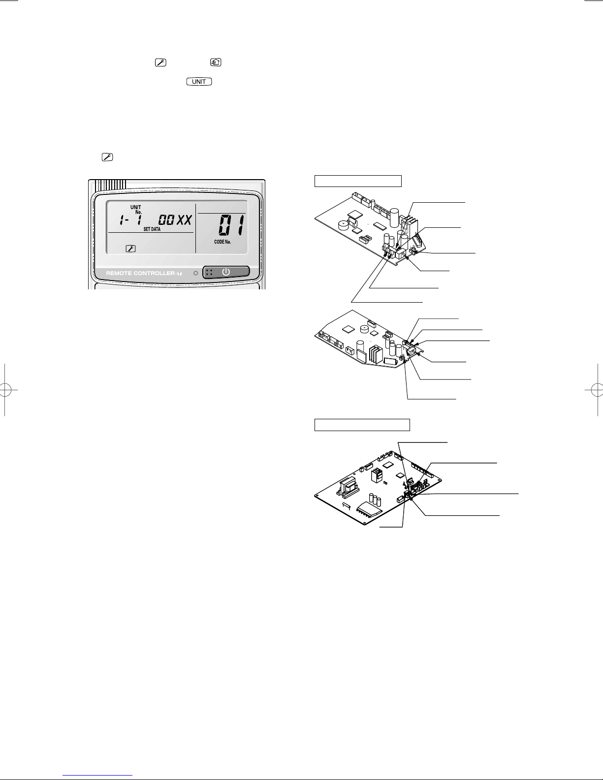
10-22-3. Checking indoor unit addresses
Use the remote controller to check the addresses of the indoor
units. Press and hold the
button and button for 4
seconds or longer (simple settings mode, “ALL” appears on the
remote controller). Then press the
button and select the
indoor address.
(For the system addresses of the No. 1 outdoor unit, each time
the button is pressed, the address changes as follows: 1-1, 1-2,
...)
The indoor unit fan operates only at the selected indoor unit.
Confirm the indoor unit address. (For the system addresses of
the No. 2 outdoor unit, the displayed addresses are 2-1, 2-2, ...)
Press the
button again to return to the normal remote
controller mode.
Fig. 10-20
10-22-4. Indicating (marking) the indoor and outdoor unit
combination number
Indicate (mark) the number after automatic address setting is
completed.
(1) So that the combination of each indoor unit can be easily
checked when multiple units are installed, ensure that
the indoor and outdoor unit numbers correspond to the
system address number on the outdoor unit control PCB,
and use a magic marker or similar means which cannot
be easily removed to indicate the numbers in an easily
visible location on the indoor units (near the indoor unit
nameplates).
Example: (Outdoor) 1 – (Indoor) 1, 2...
(Outdoor) 2 – (Indoor) 1, 2...
(2) These numbers will be needed for maintenance. Be sure to
indicate them.
● Check that the 220 – 240 V AC wiring is not connected to the
inter-unit control wiring connector terminal.
If 220 – 240 V AC is accidentally applied, the indoor or
outdoor unit control PCB fuse (0.5 A for both indoor and
outdoor units) will blow in order to protect the PCB. Correct
the wiring connections, then disconnect the 2P connectors
(indoor: blue, OC) (outdoor: blue, serial 1) that are
connected to the PCB, and replace them with 2P connectors
(indoor: brown, EMG) (outdoor: brown, serial 2).
If operation is still not possible after changing the brown
connectors, try cutting the varistor (black) (both indoor and
outdoor).
(Be sure to turn the power OFF before performing this work.)
Indoor unit control PCB
2 HP
2P connector (brown)
2P connector (blue)
3 HP
Outdoor unit control PCB
Outdoor unit control PCB
3 – 6 HP
3 – 6 HP
Varistor (black)
VA002
Fuse (0.5A)
CHK (2P plug)
SW103
Fuse (0.5A)
2P connector (blue)
2P connector (brown)
Varistor (black)
VA002
CHK (2P plug)
Varistor (black)
Varistor (black)
VA002
VA002
Terminal plug (black)
Terminal plug (black)
ON
OFF
TEST
SW103
TEST
ON
OFF
HW Type (for Link Wiring)
■
10-23. Caution
● This unit may be used in a single-type refrigerant
system where 1 outdoor unit is connected to 1 indoor
unit, and also in a system where 1 outdoor unit is
connected to multiple indoor units (maximum 4).
● If link wiring is used, set the outdoor unit system address
to allow the combination of indoor and outdoor units to be
identified. At the same time, indicate the indoor-outdoor unit
combination number in a location where it can be checked
easily (near the indoor unit nameplates). (This number will
be required for subsequent maintenance. Refer to 10-26-3,
-4.)
● Request that the customer be present when the test run is
performed. At this time, explain the operation manual and
have the customer perform the actual steps.
● Be sure to pass the manuals and warranty certificate to the
customer.
62
Fuse
Fuse
0.5 A
0.5 A
Serial 2 (brown) connector
Serial 2 (brown) connector
Serial 1 (blue) connector
Serial 1 (blue) connector
Fig. 10-21

10-24. Test Run Procedure
Turn ON
the indoor
and outdoor
power.
(Automatic
Address)
Recheck the items to check
before the test run.
Check the combination (wiring) of
indoor and outdoor units.
YES
Is system “single-type”?
(1 indoor unit is connected
to 1 outdoor unit)
NO
Are multiple outdoor units
used?
YES
(See 10-26-2) How to Set the Outdoor
Unit System Address
Set the outdoor unit system
address.
(See 10-11)
(See 10-26-1)
NO
Turn ON
the indoor
and outdoor
power.
(Automatic
Address)
(See 10-26-1, -2) How to Set Automatic
Address
Set the automatic address
setting from outside unit.
Indicate (mark) the
combination number.
Set the indoor unit control
unit to “TEST”.
Can
operation be
started?
(See 10-26-3, -4)
(See 10-26-3)
NO
YES
Turn the power back ON to
the indoor unit.
(See 10-13)
Note: Check the indoor-
(See 10-25)
Refer to “Table of
Self-Diagnostic
Functions” to check
the system.
In addition, refer to
10-26 and correct any
items that need to be
corrected.
side drainage.
Fig. 10-22
63

10-25. Table of Self-Diagnostic Functions and Corrections (HW Type)
Wired remote
controller
display
Nothing is
displayed
E01 displayed
E02 displayed
E14 displayed
E04 displayed
E06 displayed
E15 displayed • Indoor unit capacity is too low. Check that the total capacities of the indoor and
E16 displayed • Indoor unit capacity is too high.
P05 displayed
P09 displayed
P12 displayed
L02
displayed
L13
L07 displayed
L10 displayed • Check outdoor operation with separate maintenance-use remote controller.
Indoor unit
receiver lamp
Nothing is
displayed.
Operation lamp
is blinking.
Standby lamp is
blinking.
Timer lamp and
Standby lamp
are blinking
alternately.
Timer lamp and
Standby lamp
are blinking
alternately.
Both the
Operation lamp
and Standby
lamp are blinking
together.
Group connection and simultaneous-operation multi
system
• Remote controller is not connected with indoor unit
correctly.
• Indoor unit power is not ON.
• Automatic address setting has not been completed.
• Inter-unit control wiring is cut or is not connected
correctly.
• Remote controller is not connected with indoor unit
correctly.
• Remote controller is not connected with indoor unit
correctly.
• Remote controller communication wiring is cut or is not
connected correctly.
• Indoor-outdoor inter-unit wiring is not connected
correctly.
• Inter-unit control wiring is cut or is not connected
correctly.
• Reversed phase or open phase in the 3-phase power at
one of the outdoor units in the group.
• Insuffi cient gas
• Ceiling panel connector at one of the indoor units in the
group is not connected correctly.
• DC fan trouble at one of the indoor units in the group. Check whether the fan holder is loose.
• Indoor-outdoor unit type mismatch. Check that the indoor and outdoor unit types are
• Remote controller communication wiring is connected to
the indoor unit, however it is set for individual operation.
Cause
Correction
Connect the remote controller correctly. Turn ON the
indoor unit power.
Check the remote controller and inter-unit control
wiring.
Perform automatic address setting (10-22).
Connect the remote controller correctly.
Check the remote controller communication wiring.
Perform automatic address setting again.
Connect the wiring correctly.
Refer to 10-22-1. Basic wiring diagram, and make the
correct setting.
outdoor units are appropriate.
Reverse 2 phases of the outdoor unit 3-phase power
and connect them correctly.
Fill up the gas appropriately.
Connect the indoor unit ceiling panel connector
correctly.
Check the wiring between the DC fan and the PCB.
correct.
Perform automatic address setting (10-22).
64

10-26. Automatic Address Setting
3-1
3-2 3-3
1-1
1-2
1-3
2-1
2-2
1
2
3
10-26-1. Basic wiring diagram
● Link wiring
NOTE
● A terminal plug (black) is attached to each of the outdoor unit
control PCBs. At only 1 outdoor unit, leave the terminal plug
short-circuit socket on the “Yes” side. At all the other outdoor
units, change the socket (from “Yes” to “No”).
● A maximum of 8 indoor units can be connected to 1 remote
controller for group control.
Terminal plate 1, 2
Indoor unit
Terminal plate 1, 2
Outdoor unit
10-26-2. Setting the outdoor unit system addresses
For basic wiring diagram (Set the system addresses: 1, 2, 3...)
Outdoor unit control PCB
System address rotary switch
(Set to “0” at time of shipment)
System address rotary switch
System address
10s
ON
20s
DIP switch
ON
3 – 6 HP
Wireless remote
controller
Remote controller communication
wiring for group control
Wired remote
controller
Remote controller communication
wiring for group control
Wireld remote
controller
Inter-unit control wiring
No. 1
Inter-unit control
wiring
No. 2 No. 3
circuit socket
circuit socket
Change the terminal
plug (black) short-
Change the terminal
plug (black) short-
* If wall-mounted type units are used for a simultaneous-
operation multi system (group control), refer to 10-16.
System Control (basic wiring diagrams and wiring
procedures) when wiring.
System address 1
(Change setting to “1”)
System address 2
(Change setting to “2”)
System address 3
(Change setting to “3”)
Fig. 10-23
2
OFF
No.
1
3 – 6 HP
3 – 6 HP
System address
0 Automatic address
(Setting at shipment = “0”)
1 (If outdoor unit is No. 1)
2 (If outdoor unit is No. 2)
11 (If outdoor unit is No. 11)
21 (If outdoor unit is No. 21)
30 (If outdoor unit is No. 30)
System address rotary switch
System address rotary switch
System address 10s digit and 20s digit
System address 10s digit and 20s digit
DIP switch
DIP switch
Automatic address
Automatic address
button (black)
button (black)
Terminal plug (black)
Terminal plug (black)
System address
10s digit
(2P DIP switch)
Both OFF
ON
ON
12
OFF
Both OFF
ON
ON
12
OFF
Both OFF
ON
ON
12
OFF
10s digit ON
ON
ON
12
OFF
20s digit ON
ON
ON
12
digit ON
ON
12
OFF
ON
OFF
10s digit and 20s
System address
(Rotary switch)
Fig. 10-24
1s place
“0” setting
“1” setting
“2” setting
“1” setting
“1” setting
“0” setting
65

Case 1
● If the power can be turned ON separately for the indoor and
outdoor units in each system:
(The indoor unit addresses can be set without running the
compressor.)
Automatic address setting from the outdoor unit (K type)
(1) Turn on the indoor and outdoor unit power for refrigerant
system 1.
Press and hold the automatic address setting button
(black) for 1 second or longer at the outdoor unit where the
power was turned ON.
The compressor operates when the power is turned ON at
a different outdoor unit.
↓
Communication for automatic address setting begins.
↓
LED 1 and 2 on the outdoor unit control PCB blink
alternately, and turn OFF when address setting is
completed.
<Approximately 4 – 5 minutes are
required.>
↓
(2) Next, turn ON the power only at the indoor and outdoor
units in a different system. Press the automatic address
setting button (black) on the outdoor unit.
↓
LED 1 and 2 on the outdoor unit control PCB blink
alternately, and turn OFF when address setting is
completed.
↓
Repeat the same procedure for each system and complete
automatic address setting.
↓
(3) Operation using the remote controller is now possible.
Case 2
● If the power cannot be turned ON separately for the indoor
and outdoor units in each system:
The compressors must be run in order to automatically set
the indoor unit addresses. Therefore perform this step after
completing the refrigerant tubing work.
(1) Turn ON the power to the indoor and outdoor units in all
refrigerant systems.
↓
When setting addresses in cooling mode
(2) Short-circuit the mode-change pin at the outdoor unit
where automatic address setting will be performed. Then
press the automatic address setting button (black).
When setting addresses in heating mode
↓
(2) Press the automatic address setting button (black) at
the outdoor unit where automatic address setting will be
performed.
↓
(3) LED 1 and 2 blink alternately. The compressors begin
running in cool (or heat) mode. Communication for
automatic address setting begins, using the temperature
changes at the indoor units.
↓
Address setting is completed when the compressors stop
and the LED indicators turn OFF. <Approximately 15
minutes is required for 1 system.>
If address setting fails, LED 1 and 2 blink simultaneously
and the alarm contents are displayed at the remote
controller.
(4) After 1 system is completed, be sure to press the
automatic address setting button (black) at the other
outdoor units to complete automatic address setting in the
same way for each system.
(5) Operation using the remote controller is now possible.
10-26-3. Checking indoor unit addresses
Use the remote controller to check the addresses of the indoor
units. Press and hold the
button and button for 4
seconds or longer (simple settings mode, “ALL” appears on the
remote controller). Then press the
button and select the
indoor address.
(For the system addresses of the No. 1 outdoor unit, each time the
button is pressed, the address changes as follows: 1-1, 1-2, ...)
The indoor unit fan operates only at the selected indoor unit.
Confirm the indoor unit address. (For the system addresses of
the No. 2 outdoor unit, the displayed addresses are 2-1, 2-2, ...)
Press the
button again to return to the normal remote
controller mode.
10-26-4. Indicating (marking) the indoor and outdoor unit
combination number
Indicate (mark) the number after automatic address setting is
completed.
(1) So that the combination of each indoor unit can be easily
checked when multiple units are installed, ensure that
the indoor and outdoor unit numbers correspond to the
system address number on the outdoor unit control PCB,
and use a magic marker or similar means which cannot
be easily removed to indicate the numbers in an easily
visible location on the indoor units (near the indoor unit
nameplates).
Example: (Outdoor) 1 – (Indoor) 1, 2...
(Outdoor) 2 – (Indoor) 1, 2...
(2) These numbers will be needed for maintenance. Be sure to
indicate them.
10-26-5. Setting a wired remote controller as a sub remote
controller
Change the remote controller address connected on the reverse
side of the remote controller switch PCB from the Main position
to the Sub position.
Remote controller address connector
Remote Controller (Main)
Checking remote controller
Remote Controller (Sub)
TIMER
To Service Technicians
To display the sensor temperature:
and buttons on the
Press both
remote controller for more than 4 seconds
together.
Change the sensor address (CODE NO.)
with
/ (SET TEMP) buttons.
Select the UNIT NO. that you want to call
with
button.
Press the
button to finish service mode.
RCU.Main
RCU.CK
RCU.Sub
RCU
TMNL.
To avoid an electric shock hazard,
WARNING
DO NOT touch any terminal on the Printed Circuit Board with a metal rod, a
screwdriver edge or bare hand
when power
is supplied.
To display the trouble history:
Press both
remote controller for more than 4 seconds
together.
Change the alarm message:
CODE NO.
(New) (Old)
Press the
mode.
RCU.ADR
TMNL.
and buttons on the
/ (SET TEMP) buttons
button to finish service
Changing method for room
temperature sensor (from Indoor unit
to RCU)
1
On the remote controller, press
+ + at the same time
for more than 4 seconds.
2
Set CODE No.
with /
(SET TEMP) button.
3
Set DATA from
with / (TIMER) button.
4
Press
Finally, Press
to
66
Fig. 10-25
Fig. 10-26

Installing the Remote Controller
● If the remote controller is to be installed onto a wall or
other surface for use, first place the remote controller in the
location where it will be installed and press
Confirm that the “signal-received” sound occurs at the indoor
unit and that the A/C begins operating.
Fasten the remote control
mount with screws.
Remote control mount
Fitting the remote control
in the mount.
Press
2
Put in
1
● Installing the batteries
(1) Press on both sides of the remote controller cover and
slide it downward to remove it.
(2) Insert 2 AAA alkaline batteries. (Pay attention to the + and
– directions.)
(3) Gently insert one end of an unfolded paper clip (or a
similar object that can fit) into the Reset hole and press the
reset button inside the hole and then put the cover back
on.
To remove the remote controller, pull it toward you.
(ON / OFF).
Fig. 10-27
Important Information Concerning Pump
Down
Observe the following items when using pump down operation
to recover the refrigerant.
(1) If the length of inter-unit tubing exceeds 30 m, pump down
cannot be used to recover the refrigerant. (The overload
protection device may be activated.)
In that case, use refrigerant recovery equipment to recover
the refrigerant.
(2) Press and hold the “Refrigerant recovery” button on the
outdoor unit PCB for 1 second or longer.
• During refrigerant recovery, LED 1 blinks and LED 2 is lit.
• Close the liquid-side valve during refrigerant recovery.
If the unit is operated for 10 minutes or longer with the
liquid-side valve open, operation will be stopped, although
no alarm will be displayed on the remote controller. If this
occurs, close the valve and restart operation.
(3) When the valve service port pressure is approximately 0.1
MPa, press the S005 (Refrigerant recovery) button again
to end refrigerant recovery.
• In order to protect the compressor, do not continue
operating to generate a negative pressure in the inter-unit
tubing.
3 – 6 HP
3 – 6 HP
IC001
IC001
System address
System address
(S002)
(S002)
Reset hole
Cover
Fig. 10-28
Precautions for remote controller installation
● Before mounting the remote controller on the wall, place the
unit at the mounting position, then turn on any fluorescent
lamps, press the ON/OFF button, and check that the air
conditioner operates correctly.
When using the remote controller to detect the room
temperature, observe the following precautions during
installation:
• Avoid locations where the remote controller will be exposed
to the direct path of air blown from the air conditioner.
• Avoid locations where the remote controller will be exposed
to direct sunlight.
• Avoid locations where the remote controller will be exposed
to direct heat sources.
10-27. Caution for Pump Down
Pump down means refrigerant gas in the system is returned
to the outdoor unit. Pump down is used when the unit is to be
moved, or before servicing the refrigerant circuit.
Auto
Auto
Refrigerant
Refrigerant
address
address
recovery
(S001)
(S001)
ON
ON
recovery
(S005)
(S005)
ON
ON
The S005 (Refrigerant recovery) button is located at the bottom right of
The S005 (Refrigerant recovery) button is located at the bottom right of
the outdoor unit PCB, as shown in the figure above.
the outdoor unit PCB, as shown in the figure above.
CAUTION
● This outdoor unit cannot collect more than the rated
refrigerant amount as shown by the nameplate on the
back.
● If the amount of refrigerant is more than that
recommended, do not conduct a pump down. In this
case use another refrigerant collecting system.
67

11. HOW TO INSTALL WIRELESS REMOTE
CONTROLLER RECEIVER
NOTE
Refer to the Instruction Manual attached to the Optional
Wireless Remote Controller Receiver.
12. MARKINGS FOR DIRECTIVE 97/23/EC
(PED)
Rating nameplate fi gure
A: Model Name Various
B: V PH Various Hz
Operating Spec. Area
Various (Not for the PED)
C: kW. A Various
G: Various
Various (Not for the PED)
Various
DD-MM-YY
D: A Various
E: Various
F: Various
Tabulation of Various data
A
OU-PSINV-25HR OU-PSINV-36HR OU-PSINV-48HR OU-PSINV-60H
B 220 - 240 V ~ 50 / 60 Hz
3.04 kW, 16.5 A 3.42 kW, 18.5 A 4.25 kW, 21.0 A 5.27 kW, 27.0 A
C
D 25 A 35 A
E 41.5 bar
F 22.1 bar
G 1.9 kg 2.8 kg 3.6 kg
68

13. APPENDIX
13-1. 4-Way Air Discharge Semi-Concealed Type
(4WK Type)
Name of Parts (Indoor Unit)
■
Water drain
Ceiling panel
(optional)
<How to clean the filter>
1. Remove the air filter from the air intake grille.
2. Use a vacuum cleaner to remove light dust. If there is sticky
dust on the filter, wash the filter in lukewarm, soapy water,
rinse it in clean water, and dry it.
<How to remove the filter>
1. Use a screwdriver to remove the bolt screw on each side
for the two latches. (Be sure to reattach the two bolt screws
after cleaning.)
2. Press on the two latches of the air intake grille with your
thumbs in the direction of the arrow to open the grille.
3. Open the air intake grille downward.
Air outlet
(4 locations)
Air intake grille
(air intake)
Care and Cleaning
■
WARNING
● For safety, be sure to turn the air conditioner off and
also to disconnect the power before cleaning.
● Do not pour water on the indoor unit to clean it. This will
damage the internal components and cause an electric
shock hazard.
Air intake and outlet side (Indoor unit)
Clean the air intake and outlet side of the indoor unit with a
vacuum cleaner brush, or wipe them with a clean, soft cloth.
If these parts are stained, use a clean cloth moistened with
water. When cleaning the air outlet side, be careful not to force
the vanes out of place.
CAUTION
● Never use solvents or harsh chemicals when cleaning
the indoor unit. Do not wipe plastic parts using very hot
water.
● Some metal edges and the fins are sharp and may cause
injury if handled improperly; be especially careful when
you clean these parts.
● The internal coil and other components must be cleaned
regularly. Consult your dealer or service center.
Air filter
The air filter collects dust and other particles from the air and
should be cleaned at regular intervals as indicated in the table
below or when the filter indication (
) on the display of the
remote control unit (wired type) shows that the filter needs
cleaning. If the filter gets blocked, the efficiency of the air
conditioner drops greatly.
Type Period
4WK Six months
NOTE
The frequency with which the filter should be cleaned depends
on the environment in which the unit is used.
CAUTION
● When cleaning the air filter, never remove the safety
chain. If it is necessary to remove it for servicing and
maintenance inside, be sure to reinstall the safety chain
securely (hook on the grille side) after the work.
● When the filter has been removed, rotating parts (such
as the fan), electrically charged areas, etc. will be
exposed in the unit’s opening. Bear in mind the dangers
that these parts and areas pose, and proceed with the
work carefully.
4. Remove the air filter attached to the air intake grille.
Latch
Safety
Air intake
grille
Bolt screw
chain
Air filter
CAUTION
● Certain metal edges and the condenser fins are sharp
and may cause injury if handled improperly; special care
should be taken when you clean these parts.
● Periodically check the outdoor unit to see if the air outlet
or air intake is clogged with dirt or soot.
● The internal coil and other components must also be
cleaned periodically. Consult your dealer or service
center.
Care: After a prolonged idle period
Check the indoor and outdoor unit air intakes and outlets for
blockage; if there is a blockage, remove it.
Care: Before a prolonged idle period
● Operate the fan for half a day to dry out the inside.
● Disconnect the power supply and also turn off the circuit
breaker.
● Clean the air filter and replace it in its original position.
● Outdoor unit internal components must be checked and
cleaned periodically. Contact your local dealer for this
service.
69

Troubleshooting
■
If your air conditioner does not work properly, first check the
following points before requesting service. If it still does not
work properly, contact your dealer or a service center.
Trouble Possible Cause Remedy
Air conditioner
does not run at
all
Compressor
runs but soon
stops
Poor cooling
(or heating)
performance
1. Power failure.
2. Leakage circuit breaker
has tripped.
3. Line voltage is too low.
4. Operation button is turned
off.
5. The wired remote control
unit or heat pump is
malfunctioning.
(The inspection mark
and the letters E, F, H,
L, P in combination with
numbers appear on the
LCD of the wired remote
control unit.)
1. Obstruction in front of
condenser coil
1. Dirty or clogged air filter.
2. Heat source or many
people in room.
3. Doors and/or windows are
open.
4. Obstacle near air intake or
air discharge port.
5. Thermostat is set too high
for cooling (or too low for
heating).
6. (Defrosting system does
not work.)
1. After a power
outage, press
ON/OFF operation
button on the wired
remote control unit.
2. Contact service
center.
3. Consult your
electrician or dealer.
4. Press the button
again.
5. Consult your dealer.
1. Remove obstruction
1. Clean air filter to
improve the airflow.
2. Eliminate heat
source if possible.
3. Shut them to keep
the heat (or cold)
out.
4. Remove it to ensure
good airflow.
5. Set the temperature
lower (or higher).
6. (Consult your
dealer.)
13-2. Concealed Duct Type (D Type)
Name of Parts (Indoor Unit)
■
CONCEALED DUCT
Flexible duct (optional)
Water drain
Canvas duct (optional)
Air intake grille
(air intake)
Air outlet grille
(optional)
Care and Cleaning
■
(optional)
WARNING
● For safety, be sure to turn the air conditioner off and
also to disconnect the power before cleaning.
● Do not pour water on the indoor unit to clean it. This will
damage the internal components and cause an electric
shock hazard.
Air intake and outlet side (Indoor unit)
Clean the air intake and outlet side of the indoor unit with a
vacuum cleaner brush, or wipe them with a clean, soft cloth.
If these parts are stained, use a clean cloth moistened with
water. When cleaning the air outlet side, be careful not to force
the vanes out of place.
Tips for Energy Saving
■
Avoid
● Do not block the air intake and outlet of the unit. If either
is obstructed, the unit will not work well, and may be
damaged.
● Do not let direct sunlight into the room. Use sunshades,
blinds or curtains. If the walls and ceiling of the room are
warmed by the sun, it will take longer to cool the room.
Do
● Always try to keep the air filter clean. (Refer to “Care and
Cleaning”.) A clogged filter will impair the performance of the
unit.
● To prevent conditioned air from escaping, keep windows,
doors and any other openings closed.
NOTE
Should the power fail while the unit is running
If the power supply for this unit is temporarily cut off, the unit will
automatically resume operation once power is restored using
the same settings before the power was cut off.
CAUTION
Never use solvents or harsh chemicals when cleaning
●
the indoor unit. Do not wipe plastic parts using very hot
water.
Some metal edges and the fins are sharp and may cause
●
injury if handled improperly; be especially careful when
you clean these parts.
The internal coil and other components must be cleaned
●
regularly. Consult your dealer or service center.
Type Period
D
(Depends on filter
specifications)
70

*Concealed duct type (D):
An air filter is not provided with this air conditioner at the time of
shipment. To get clean air and to extend the service life of the
air conditioner, an air filter must be installed in the air intake.
For installation and cleaning the air filter, consult your dealer or
service center.
NOTE
The frequency with which the filter should be cleaned depends
on the environment in which the unit is used.
<How to clean the filter>
1. Remove the air filter from the air intake side.
2. Use a vacuum cleaner to remove light dust. If there is sticky
dust on the filter, wash the filter in lukewarm, soapy water,
rinse it in clean water, and dry it.
Troubleshooting
■
If your air conditioner does not work properly, first check the
following points before requesting service. If it still does not
work properly, contact your dealer or a service center.
Trouble Possible Cause Remedy
Air
conditioner
does not run
at all
Compressor
runs but
soon stops
Poor cooling
(or heating)
performance
Tips for Energy Saving
■
1. Power failure.
2. Leakage circuit
breaker has tripped.
3. Line voltage is too low.
4. Operation button is
turned off.
5. The wired remote
control unit or
heat pump is
malfunctioning.
(The inspection mark
and the letters E, F,
H, L, P in combination
with numbers appear
on the LCD of the
wired remote control
unit.)
1. Obstruction in front of
condenser coil
1. Dirty or clogged air
filter.
2. Heat source or many
people in room.
3. Doors and/or windows
are open.
4. Obstacle near air
intake or air discharge
port.
5. Thermostat is set too
high for cooling (or too
low for heating).
6. (Defrosting system
does not work.)
1. After a power outage,
press ON/OFF operation
button on the wired remote
control unit.
2. Contact service center.
3. Consult your electrician or
dealer.
4. Press the button again.
5. Consult your dealer.
1. Remove obstruction
1. Clean air filter to improve
the airflow.
2. Eliminate heat source if
possible.
3. Shut them to keep the heat
(or cold) out.
4. Remove it to ensure good
airflow.
5. Set the temperature lower
(or higher).
6. (Consult your dealer.)
Avoid
● Do not block the air intake and outlet of the unit. If either
is obstructed, the unit will not work well, and may be
damaged.
● Do not let direct sunlight into the room. Use sunshades,
blinds or curtains. If the walls and ceiling of the room are
warmed by the sun, it will take longer to cool the room.
Do
● Always try to keep the air filter clean. (Refer to “Care and
Cleaning.”) A clogged filter will impair the performance of the
unit.
● To prevent conditioned air from escaping, keep windows,
doors and any other openings closed.
NOTE
Should the power fail while the unit is running
If the power supply for this unit is temporarily cut off, the unit will
automatically resume operation once power is restored using
the same settings before the power was interrupted.
13-3. Ceiling-Mounted Type (C Type)
Name of Parts
■
Air outlet
Air outlet
Water drain
Water drain
(Drain pipe can be
(Drain pipe can be
connected to either
connected to either
the left or right side.)
the left or right side.)
Air intake grille
Air intake grille
(air intake)
(air intake)
Care and Cleaning
■
WARNING
● For safety, be sure to turn the air conditioner off and
also to disconnect the power before cleaning.
● Do not pour water on the indoor unit to clean it. This will
damage the internal components and cause an electric
shock hazard.
Air intake and outlet side (Indoor unit)
Clean the air intake and outlet side of the indoor unit with a
vacuum cleaner brush, or wipe them with a clean, soft cloth.
If these parts are stained, use a clean cloth moistened with
water. When cleaning the air outlet side, be careful not to force
the vanes out of place.
CAUTION
● Never use solvents or harsh chemicals when cleaning
the indoor unit. Do not wipe plastic parts using very hot
water.
● Some metal edges and the fins are sharp and may cause
injury if handled improperly; be especially careful when
you clean these parts.
● The internal coil and other components must be cleaned
regularly. Consult your dealer or service center.
Air filter
The air filter collects dust and other particles from the air and
should be cleaned at regular intervals as indicated in the table
below or when the filter indication (
) on the display of the
remote control unit (wired type) shows that the filter needs
cleaning. If the filter gets blocked, the efficiency of the air
conditioner drops greatly.
Type Period
C 2 weeks
NOTE
The frequency with which the filter should be cleaned depends
on the environment in which the unit is used.
71
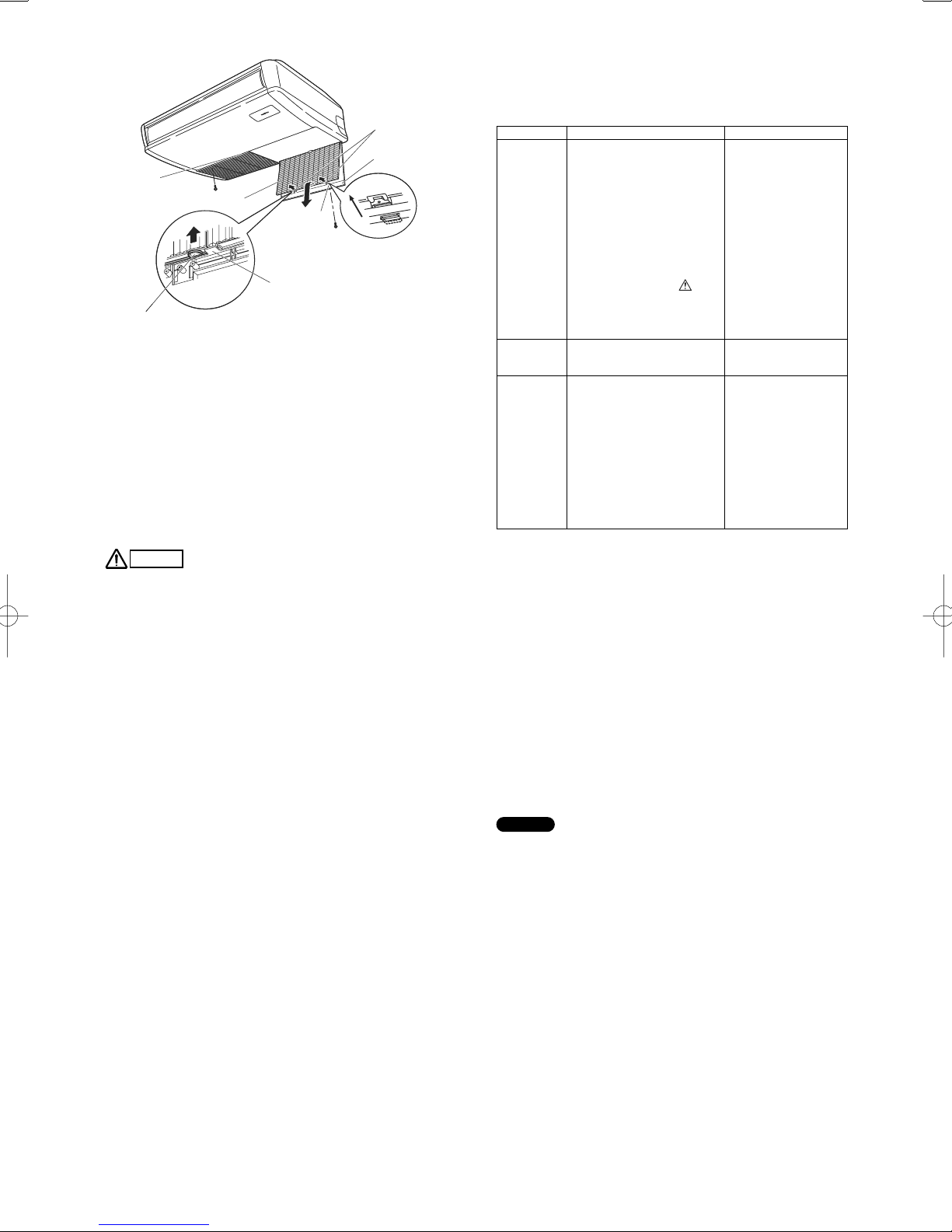
Air filter finger-hold
Air filter finger-hold
Air intake grill
Air intake grill
Air intake grill
Air intake grill
finger-hold
finger-hold
Air filter finger-hold
Air filter finger-hold
* Take hold of the finger-hold on the air filter, pull it toward you.
* Take hold of the finger-hold on the air filter, pull it toward you.
Screw
Screw
Air filter
Air filter
Latch
Latch
Hook
Hook
Screw
Screw
Slide
Slide
<How to clean the filter>
1. Remove the air filter from the air intake grille.
2. Use a vacuum cleaner to remove light dust. If there is sticky
dust on the filter, wash the filter in lukewarm, soapy water,
rinse it in clean water, and dry it.
<How to remove the filter>
1. Take hold of the finger-hold on the air intake grille and
press it to the rear, and the grille will open downward.
2. Take hold of the finger-hold on the air filter, pull it toward
you.
Troubleshooting
■
If your air conditioner does not work properly, first check the
following points before requesting service. If it still does not
work properly, contact your dealer or a service center.
Trouble Possible Cause Remedy
Air conditioner
does not run
at all
Compressor
runs but soon
stops
Poor cooling
(or heating)
performance
1. Power failure.
2. Leakage circuit breaker has
tripped.
3. Line voltage is too low.
4. Operation button is turned off.
5. The wired remote control unit
or heat pump is malfunctioning.
(The inspection mark
the letters E, F, H, L, P in
combination with numbers
appear the LCD of the wired
remote control unit.)
1. Obstruction in front of
condenser coil
1. Dirty or clogged air filter.
2. Heat source or many people
in room.
3. Doors and/or windows are
open.
4. Obstacle near air intake or air
discharge port.
5. Thermostat is set too high for
cooling
(or too low for heating).
6. (Defrosting system does not
work.)
and
1. After a power outage,
press ON/OFF
operation button on the
wired remote control
unit.
2. Contact service center.
3. Consult your electrician
or dealer.
4. Press the button again.
5. Consult your dealer.
1. Remove obstruction
1. Clean air filter to
improve the airflow.
2. Eliminate heat source if
possible.
3. Shut them to keep the
heat (or cold) out.
4. Remove it to ensure
good airflow.
5. Set the temperature
lower (or higher).
6. (Consult your dealer.)
CAUTION
● Certain metal edges and the condenser fins are sharp
and may cause injury if handled improperly; special care
should be taken when you clean these parts.
● Periodically check the outdoor unit to see if the air outlet
or air intake is clogged with dirt or soot.
● The internal coil and other components must also be
cleaned periodically. Consult your dealer or service
center.
Care: After a prolonged idle period
Check the indoor and outdoor unit air intakes and outlets for
blockage; if there is a blockage, remove it.
Care: Before a prolonged idle period
● Operate the fan for half a day to dry out the inside.
● Disconnect the power supply and also turn off the circuit
breaker.
● Clean the air filter and replace it in its original position.
● Outdoor unit internal components must be checked and
cleaned periodically. Contact your local dealer for this
service.
Tips for Energy Saving
■
Avoid
● Do not block the air intake and outlet of the unit. If either is
obstructed, the unit will not work well, and may be damaged.
● Do not let direct sunlight into the room. Use sunshades,
blinds or curtains. If the walls and ceiling of the room are
warmed by the sun, it will take longer to cool the room.
Do
● Always try to keep the air filter clean. (Refer to “Care and
Cleaning.”) A clogged filter will impair the performance of the
unit.
● To prevent conditioned air from escaping, keep windows,
doors and any other openings closed.
NOTE
Should the power fail while the unit is running
If the power supply for this unit is temporarily cut off, the unit will
automatically resume operation once power is restored using
the same settings before the power was interrupted.
72

13-4. Wall-Mounted Type (HW Type)
Name of Parts
■
Care and Cleaning
■
Air intake
Air outlet
WARNING
● For safety, be sure to turn the air conditioner off and
also to disconnect the power before cleaning.
● Do not pour water on the indoor unit to clean it. This will
damage the internal components and cause an electric
shock hazard.
Air intake and outlet side (Indoor unit)
Clean the air intake and outlet side of the indoor unit with a
vacuum cleaner brush, or wipe them with a clean, soft cloth.
If these parts are stained, use a clean cloth moistened with
water. When cleaning the air outlet side, be careful not to force
the vanes out of place.
CAUTION
● Never use solvents or harsh chemicals when cleaning
the indoor unit. Do not wipe plastic parts using very hot
water.
● Some metal edges and the fins are sharp and may cause
injury if handled improperly; be especially careful when
you clean these parts.
● The internal coil and other components must be cleaned
regularly. Consult your dealer or service center.
Air filter
The air filter collects dust and other particles from the air and
should be cleaned at regular intervals as indicated in the table
below or when the filter indication (
remote control unit (wired type) shows that the filter needs
cleaning. If the filter gets blocked, the efficiency of the air
conditioner drops greatly.
) on the display of the
Air intake grille
Air filter
When replacing the filter, make sure that the FRONT mark is
facing you.
Push it up until you hear it click back into position.
CAUTION
● Certain metal edges and the condenser fins are sharp
and may cause injury if handled improperly; special care
should be taken when you clean these parts.
● Periodically check the outdoor unit to see if the air outlet
or air intake is clogged with dirt or soot.
● The internal coil and other components must also be
cleaned periodically. Consult your dealer or service
center.
Care: After a prolonged idle period
Check the indoor and outdoor unit air intakes and outlets for
blockage; if there is a blockage, remove it.
Care: Before a prolonged idle period
● Operate the fan for half a day to dry out the inside.
● Disconnect the power supply and also turn off the circuit
breaker.
● Clean the air filter and replace it in its original position.
● Outdoor unit internal components must be checked and
cleaned periodically. Contact your local dealer for this
service.
Type Period
HW 2 weeks
NOTE
The frequency with which the filter should be cleaned depends
on the environment in which the unit is used.
<How to clean the filter>
1. Remove the air filter from the air intake grille.
2. Use a vacuum cleaner to remove light dust. If there is sticky
dust on the filter, wash the filter in lukewarm, soapy water,
rinse it in clean water, and dry it.
<How to remove the filter>
1. Move the flap on the air outlet grille to its lowest position
with the remote control unit.
2. The filter is disengaged by pushing the tab up gently. Hold
the air filter by the tab at the bottom, and pull downward.
73

Troubleshooting
■
If your air conditioner does not work properly, first check the
following points before requesting service. If it still does not
work properly, contact your dealer or a service center.
Trouble Possible Cause Remedy
Air
conditioner
does not run
at all
Compressor
runs but
soon stops
Poor cooling
(or heating)
performance
1. Power failure.
2. Leakage circuit breaker has
tripped.
3. Line voltage is too low.
4. Operation button is turned
off.
5. The wired remote control
unit or heat pump is
malfunctioning.
(The inspection mark
the letters E, F, H, L, P in
combination with numbers
appear on the LCD of the
wired remote control unit.)
1. Obstruction in front of
condenser coil
1. Dirty or clogged air filter.
2. Heat source or many people
in room.
3. Doors and/or windows are
open.
4. Obstacle near air intake or
air discharge port.
5. Thermostat is set too high
for cooling
(or too low for heating).
6. (Defrosting system does not
work.)
and
1. After a power outage,
press ON/OFF
operation button on
the wired remote
control unit.
2. Contact service
center.
3. Consult your
electrician or dealer.
4. Press the button
again.
5. Consult your dealer.
1. Remove obstruction
1. Clean air filter to
improve the airflow.
2. Eliminate heat source
if possible.
3. Shut them to keep the
heat (or cold) out.
4. Remove it to ensure
good airflow.
5. Set the temperature
lower (or higher).
6. (Consult your dealer.)
Tips for Energy Saving
■
Avoid
● Do not block the air intake and outlet of the unit. If either is
obstructed, the unit will not work well, and may be damaged.
● Do not let direct sunlight into the room. Use sunshades,
blinds or curtains. If the walls and ceiling of the room are
warmed by the sun, it will take longer to cool the room.
Do
● Always try to keep the air filter clean. (Refer to "Care and
Cleaning.”) A clogged filter will impair the performance of the
unit.
● To prevent conditioned air from escaping, keep windows,
doors and any other openings closed.
NOTE
Should the power fail while the unit is running
If the power supply for this unit is temporarily cut off, the unit will
automatically resume operation once power is restored using
the same settings before the power was interrupted
74

75

Instructions for venting fluorinated gas
EN (English)
Do not vent R407C into atmosphere : R407C is a fluorinated greenhouse gas, covered by
Kyoto Protocol, with a Global Warming Potential (GWP) = 1530
Do not vent R410A into atmosphere : R410A is a fluorinated greenhouse gas, covered by
Kyoto Protocol, with a Global Warming Potential (GWP) = 1730
IT (Italian)
Non disperdere R407C nell’atmosfera : R407C è un gas fluorinato a effetto serra, coperto dal
protocollo di Kyoto, con potenziale di riscaldamento globale (GWP) = 1530
Non disperdere R410A nell’atmosfera : R410A è un gas fluorinato a effetto serra, coperto dal
protocollo di Kyoto, con potenziale di riscaldamento globale (GWP) = 1730
FR (French)
Ne déchargez pas R407C dans l’atmosphère : R407C est un gaz fluoré à effet serre, couvert
par le protocole de Kyoto, avec un potentiel de chauffage global (GWP) = 1530
Ne déchargez pas R410A dans l’atmosphère : R410A est un gaz fluoré à effet serre, couvert
par le protocole de Kyoto, avec un potentiel de chauffage global (GWP) = 1730
DE (German)
Zerstreuen Sie R407C in Atmosphäre nicht : R407C ist ein fluoriertes Gas, abgedeckt durch
Kyoto Protokoll, mit einem globalen wärmenden Potential (GWP) = 1530
Zerstreuen Sie R410A in Atmosphäre nicht : R410A ist ein fluoriertes Gas, abgedeckt durch
Kyoto Protokoll, mit einem globalen wärmenden Potential (GWP) = 1730
ES (Spanish)
No expulsar R407C a la atmósfera : el R407C es un gas fluorado de efecto invernadero,
cubierto por el protocolo de Kyoto, con potencial de calentamiento global (GWP) = 1530
No expulsar R410A a la atmósfera : el R410A es un gas fluorado de efecto invernadero,
cubierto por el protocolo de Kyoto, con potencial de calentamiento global (GWP) = 1730
PO (Portuguese)
Não exale R407C na atmosfera : R407C é um fluorinated gás, coberto pelo protocolo de
Kyoto, com um global Protencial Aquecendo-se (GWP) = 1530
Não exale R410A na atmosfera : R410A é um fluorinated gás, coberto pelo protocolo de
Kyoto, com um global Protencial Aquecendo-se (GWP) = 1730
GR (Greek)
ȂȘȞ ĮİȡȓıIJİ R407C ıIJȘȞ ĮIJȝȩıijĮȚȡĮ R407C İȓȞĮȚ ȑȞĮ ijșȠȡȚȦȝȑȞȠ șİȡȝȠțȒʌȚȠ ĮȑȡȚȠ ʌȠȣ
țĮȜȪʌIJİIJĮȚ Įʌȩ IJȠ ʌȡȦIJȩțȠȜȜȠ IJȠȣ ȀȚȩIJȠ ȝİ ȑȞĮȞ ıijĮȚȡȚțȩ ǻȣȞĮIJȩIJȘIJĮ șȑȡȝĮȞıȘȢ (GWP) =
1530
ȂȘȞ ĮİȡȓıIJİ R410A ıIJȘȞ ĮIJȝȩıijĮȚȡĮ R410A İȓȞĮȚ ȑȞĮ ijșȠȡȚȦȝȑȞȠ șİȡȝȠțȒʌȚȠ ĮȑȡȚȠ ʌȠȣ
țĮȜȪʌIJİIJĮȚ Įʌȩ IJȠ ʌȡȦIJȩțȠȜȜȠ IJȠȣ ȀȚȩIJȠ ȝİ ȑȞĮȞ ıijĮȚȡȚțȩ ǻȣȞĮIJȩIJȘIJĮ șȑȡȝĮȞıȘȢ (GWP) =
1730
 Loading...