

Page 1
SMARTYCAM
User Manual
Page 2

SmartyCam
User Manual
Release 1.22 – firmware version 1.03.10
Dear Customer,
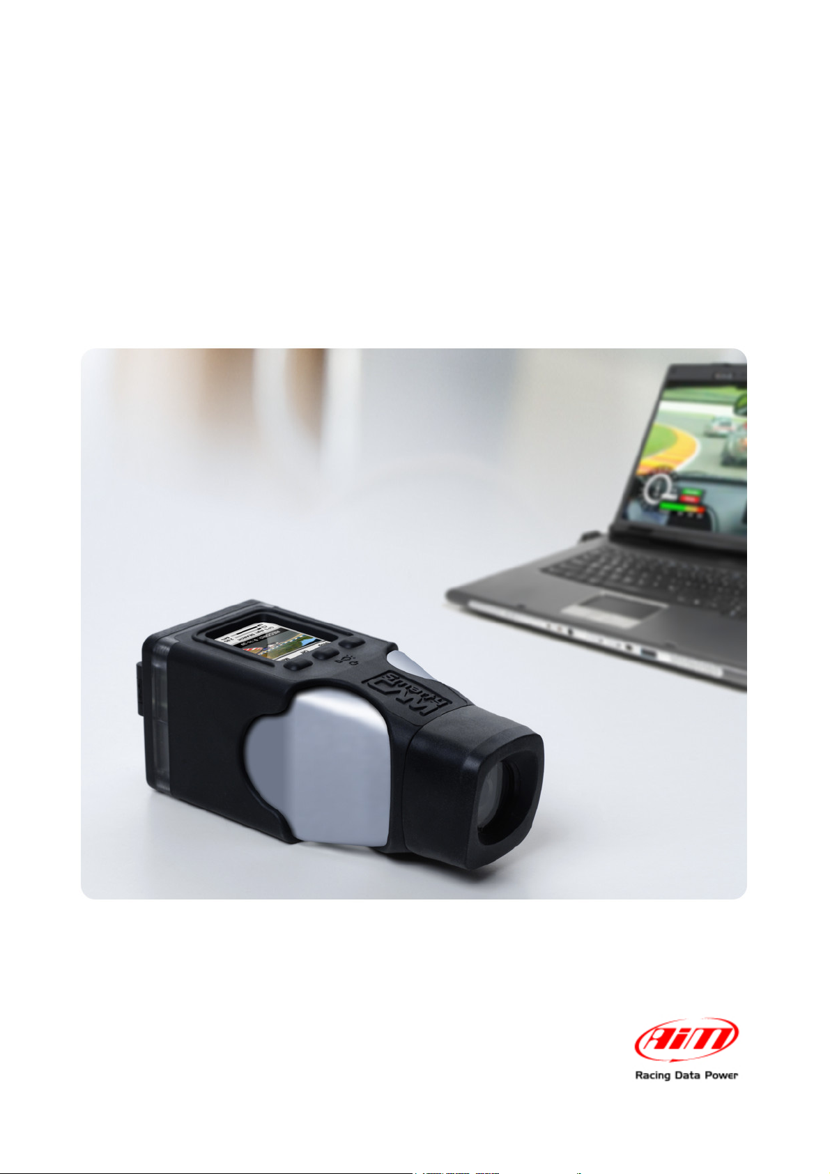
SmartyCam, the new on board camera with data overlay, descends from the great AIM
experience in developing data acquisition systems, mainly for motorsports applications.
SmartyCam can review racing performances on a PC or TV, merging crystal clear images
with graphical data coming from integrated GPS and three-axial accelerometer, as well as
from the ECU (Engine Control Unit from here onward ECU) or from an AIM logger: that is
why SmartyCam can be used in any situation, on any sort of vehicle.
Acquired data can be overlaid to frames in a great variety of formats, configurable by the
user. On a Micro SD card hours of movies and sounds can be saved: ratio depends on the
video quality and is approximately 1 hour = 2 Giga.
It is recommended to periodically check www.smartycam.com for software and/or firmware
updates or – recommended option – subscribe the www.smartycam.com newsletter to
receive all updates in real time.
Warning: this user manual is regularly updated. All new versions can be found on
www.smartycam.com. Please make sure your manual is the latest version
available: the issue number of each manual is reported on the top of the page.
www.smartycam.com
2
Page 3

SmartyCam
User Manual
Release 1.22 – firmware version 1.03.10
INDEX
SmartyCam Quick Guide ................................................................................................... 5
1 – SmartyCam stand alone ....................................................................................................................... 5
2 – SmartyCam Slave (connected to an AIM device or the ECU via ECU Bridge) ................................ 6
Chapter 1 – SmartyCam: kit and optional items ............................................................. 7
1.1 – SmartyCam kits .................................................................................................................................. 7
1.1.1 – SmartyCam part numbers ............................................................................................................. 8
1.2 – SmartyCam Bridges kits .................................................................................................................... 9
1.2.1 – ECU Bridge kits ............................................................................................................................. 9
1.2.2 – RPM Bridge kit .............................................................................................................................. 9
1.3 – SmartyCam optional items: cables, external microphone and external GPS ............................ 10
1.3.1 – External GPS module working mode .......................................................................................... 10
Chapter 2 – Data sampled by SmartyCam stand alone/slave ...................................... 11
Chapter 3 – SmartyCam connections ............................................................................ 12
3.1 – Connecting SmartyCam stand alone ............................................................................................. 12
3.2 – Connecting SmartyCam Slave expansion with SMC Bridges ..................................................... 13
3.3 – SmartyCam in Slave expansion mode with AIM loggers ............................................................. 14
Chapter 4 – How to charge SmartyCam battery ............................................................ 15
4.1 – Battery charging via USB ................................................................................................................ 15
4.2 – Battery charging via connector ...................................................................................................... 15
Chapter 5 – SmartyCam configuration ........................................................................... 16
Chapter 6 – How to use SmartyCam .............................................................................. 17
6.1 – “Battery and Memory Status” field ................................................................................................. 17
6.2 – How to switch SmartyCam on/off ................................................................................................... 18
6.3 – “Online” status (or mode) ............................................................................................................... 19
6.4 – SmartyCam “MENU” ........................................................................................................................ 19
6.4.1 – “LAP MANAGEMENT” option ..................................................................................................... 19
6.4.2 – “SETTINGS” option ..................................................................................................................... 20
6.4.2.1 – “CONF LOAD” option ............................................................................................................... 20
6.4.2.2 – Accelerometer calibration: “ACCEL CALIBR” option ............................................................... 21
6.4.2.3 – “TRACKS” option ..................................................................................................................... 21
6.5 – How to record videos ....................................................................................................................... 22
6.5.1 – Manual recording ........................................................................................................................ 22
6.5.2 – Automatic recording .................................................................................................................... 23
6.6 – SmartyCam recording support ....................................................................................................... 23
Chapter 7– Downloading data and viewing SmartyCam videos .................................. 24
7.1 – Downloading data ............................................................................................................................ 24
7.2 – Viewing SmartyCam videos ............................................................................................................ 24
7.2.1 – Viewing SmartyCam videos on the PC ....................................................................................... 24
7.2.2 – Viewing SmartyCam videos on the TV ....................................................................................... 24
Chapter 8 – SmartyCam Maintenance ............................................................................ 25
8.1 – How to update SmartyCam firmware through the micro SD ....................................................... 25
Appendix “A” – Technical specifications ...................................................................... 26
Appendix “B” – SmartyCam Pinout ............................................................................... 27
www.smartycam.com
3
Page 4

SmartyCam
User Manual
Release 1.22 – firmware version 1.03.10
INTRODUCTION
SmartyCam features three different working modes.
Stand alone: for non-motorsport applications or for motorsport applications whenever
there is no ECU nor AIM data acquisition system/data logger (from here onward: logger).
Slave connected to the vehicle ECU: for motorsport applications to sample data from the
ECU with no need of additional sensors. In this case an AIM ECU Bridge is required. It is
described in www.smartycam.com, “Accessories” area.
Slave connected to an AIM logger: for motorsport applications when a detailed analysis
of performances is needed, desired. In this case the ECU bridge is not required because
connection to the vehicle ECU is made using an AIM logger. SmartyCam is supported by
the following loggers:
• MXL,
• EVO3,
• EVO4,
• MyChron4.
Information concerning these loggers are on “Car” and “Kart” – MyChron4 only – section
of www.aim-sportline.com.
There is also an intermediate slave connection mode that needs an optional RPM Bridge.
This new AIM device shows on SmartyCam video, but does not to record, RPM value of
the vehicle engine the on-board camera is installed on. This is also possible when the
vehicle has no ECU or the ECU does not communicate through CAN/RS232 or K line
communication protocol (Nascar car for instance). Information concerning this device are
available at www.smartycam.com – “Accessories” section.
www.smartycam.com
4
Page 5

SmartyCam
User Manual
Release 1.22 – firmware version 1.03.10
SmartyCam Quick Guide
SmartyCam is a very flexible product: it has been designed to fit the needs of an entry
level user as well as these of a more professional motorsport driver. This flexibility implies
the need for the user to configure the logger using the proper software.
This quick guide includes all essential information for an easy and immediate SmartyCam
use. Any other information is to be looked for in the indicated chapter/paragraph.
1 – SmartyCam stand alone
Battery charge
It is recommended to charge the battery via socket (Chapter 4) and not via PC. In case of
very first usage or after a long period of inactivity please ensure SmartyCam charge status
is at least 80%.
Insert the micro SD
The housing is under the rear flip of the product (close carefully after insertion).
Power on SmartyCam (and enable “AUTO REC” function if desired)
Power on is made through the central button (Paragraph 6.2)
SmartyCam comes with “AUTO REC” function disabled: recording is started/stopped
manually pressing “Rec” and – at the end of the recording session – “Stop” (Paragraph
6.5.1). Enabling “AUTO REC” recording is automatically started/stopped when
acceleration exceeds the threshold set by user (Paragraph 6.5.2). This way there is no
need of intervention on the camera while travelling.
Install SmartyCam in the desired position
Install SmartyCam in the right position to shoot: the display shows a frame preview.
Optional kits are available for any kind of installation (roll-bar, with suction cup, etc.). They
are shown on www.smartycam.com, Accessories>>Bracket kits.
Calibrating the accelerometer
Accelerometer calibration is important because it influences the accuracy of acceleration
measurement as well as the taken images centring (Paragraph 6.4.2.2).
Recording movies
Shooting can be managed manually or automatically (Paragraph 6.5). SmartyCam movies
can be in .mov or in .avi format with H.264 codec. It is suggested to use VLC player
(downloadable from http://www.videolan.org/vlc/ ). To edit movies use AVS Video Editor
(downloadable from http://www.avsmedia.com/it/avs-video-editor.aspx).
Downloading movies on a PC
SmartyCam allows to download data both via USB and manually extracting the micro SD
from the rear flip of SmartyCam and inserting it in the PC reader (Chapter 7). It is
reminded to use only a 2.0 type USB port.
Install SmartyManager software on the PC
It is needed to: download new firmware versions from www.smartycam.com
– Updates
area – and update SmartyCam functionalities, modify/add/delete overlay configurations
and download/see movies (Chapter 7). SmartyManager is on the CD of SmartyCam kit
and can be downloaded from the same website. Periodically check possible new
software/firmware releases.
5
www.smartycam.com
Page 6

SmartyCam
User Manual
Release 1.22 – firmware version 1.03.10
2 – SmartyCam Slave (connected to an AIM device or the ECU via ECU
Bridge)
Install SmartyManager and Race Studio 2 software on the PC. The first one is needed
to download new firmware versions from download area of www.smartycam.com and
update SmartyCam functionalities, modify/add/delete overlay configurations – if desired –
and download/see SmartyCam movies (Chapter 7). The CD included in SmartyCam kit
contains SmartyManager and Race Studio 2 that can also be downloaded from
www.aim-sportline.com, download area >>software section. Periodically check possible
new software/firmware releases.
Configure the logger (or Bridge) with Race Studio 2
See Race Studio Configuration user manual, downloadable from download
area>>software section of www.aim-sportline.com to know how to configure each logger
and Bridge.
Configure SmartyCam with SmartyManager
See SmartyManager user manual downloadable from www.aim-sportline.com download
area>>software section.
Connect SmartyCam to the logger/Bridge
Each logger connection mode is shown in “Connection” area of www.smartycam.com.
Insert the micro SD
The housing is under the rear flip of the product (carefully close after insertion).
Install SmartyCam in the desired position
Install SmartyCam in the right position to shoot: the display shows a frame preview.
Optional kits are available for any kind of installation (roll-bar, with suction cup, etc.). They
are shown on www.smartycam.com, Accessories>>Bracket kits.
Power on SmartyCam
SmartyCam switches on as soon as the camera detects the 12V power.
Power on is also made through the central button (Paragraph 6.2)
Calibrating the accelerometer
Accelerometer calibration is important because it influences the accuracy of acceleration
measurement as well as the taken images centring (Paragraph 6.4.2.2).
Recording movies
Shooting can be managed both manually and automatically (Paragraph 6.5). SmartyCam
movies are in .mov or in .avi format with H.264 codec. It is suggested to use VLC
player (downloadable from http://www.videolan.org/vlc/ ). To edit movies use AVS Video
Editor (downloadable from http://www.avsmedia.com/it/avs-video-editor.aspx).
Downloading movies on a PC
SmartyCam allows to download data both via USB and manually extracting the micro SD
from the rear flip of SmartyCam and inserting it in the PC reader (Chapter 7). It is
reminded to use only a 2.0 type USB port.
6
www.smartycam.com
Page 7

SmartyCam
User Manual
Release 1.22 – firmware version 1.03.10
Chapter 1 – SmartyCam: kit and optional items
SmartyCam package includes a complete kit that permits standard usage: in this manual
some optional items are also shown, which can be useful in particular situations.
1.1 – SmartyCam kits
Stand alone kit:
1 – SmartyCam;
1 – power supply;
1 – adapter;
1 – external GPS module;
1 – power and battery charge cable;
1 – USB cable for data download and battery charge;
1 – 4 Giga Micro SD;
1 – SmartyCam user manual;
1 – SmartyManager user manual
1 – CD containing SmartyManager software and USB driver.
Slave kit with AIM Bridge or logger (EVO3 Pro/Pista, EVO4, MXL Strada/Pista /Pro05,
MyChron4):
1 – SmartyCam;
1 – power supply;
1 – adapter;
1 – external GPS module;
1 – 2m or 4m CAN cable (for AIM logger/Bridge connection);
1 – USB cable for data download and battery charge;
1 – 4 Giga Micro SD;
1 – SmartyCam user manual;
1 – SmartyManager user manual;
1 – CD containing SmartyManager + Race Studio 2 software and USB driver.
Warning: to use SmartyCam in slave mode an ECU Bridge or an RPM Bridge
(optional) or the appropriate AIM logger is needed.
www.smartycam.com
7
Page 8

SmartyCam
User Manual
Release 1.22 – firmware version 1.03.10
1.1.1 – SmartyCam part numbers
As shown here below, SmartyCam part number is made up of 11 alphanumeric types, 7 of
which already settled.
Here follows explanation of how o determine the four remaining types.
CAN or power cable selection:
To use the on board camera in standalone mode a power cable is needed. All
cables are available in 2 or 4 meters length: generally the short one is
recommended for bikes and karts while the 4 meters one for cars.
To use the camera with Bridge or logger a CAN cable and not a power cable is
needed.
Available options are:
1 – Power cable 2m long
2 – Power cable 4m long
3 – CAN cable 2m long
4 – CAN cable 4m long
GPS cable length selection:
Available options are:
1 – GPS cable 2m long
2 – GPS cable 4m long
Lens type selection:
Two lens types are available: with 67° horizontal field of view (HFOV) or a wider
one, with 84°(HFOV). The 84° lens is recommended for kart, bike, formula car
and open roof car in general. The 67° lens is the best choice for closed roof cars
(i.e. touring cars).
Available options are:
S – 67° lens
W – 84° lens
Optional microphone selection:
If no additional microphone is needed, input 0. If an additional microphone is
needed choose the cable chosen above (step 1):
1. with a jack (to connect a microphone of your choice), or alternatively
2. with a microphone (supplied by AIM) already jointed to the cable
Available options are:
0 – No additional microphone
1 – Power cable or CAN cable with Jack for external microphone
2 – Power cable or CAN cable with external microphone.
www.smartycam.com
8
Page 9

SmartyCam
User Manual
Release 1.22 – firmware version 1.03.10
1.2 – SmartyCam Bridges kits
There are two available Briges for SmartyCam: ECU Bridge and RPM Bridge.
1.2.1 – ECU Bridge kits
There are two available ECU Bridges, required to connect SmartyCam to the vehicle
ECU. Their part number changes according to the communication protocol they are
equipped with.
• ECU Bridge with CAN/RS232 communication protocol: X90BGGPI2R
• ECU Bridge with CAN/K Line communication protocol: X90BGGPI2K
Each ECU Bridge kit includes:
1 – ECU Bridge
1 – USB cable.
Refer to www.smartycam.com, accessories area for further information concerning ECU
Bridges.
1.2.2 – RPM Bridge kit
RPM Bridge is needed to view RPM values on SmartyCam videos. The kit includes:
• RPM Bridge
• USB cable
RPM Bridge kit part number is: X90BGGP3RPM
Refer to www.smartycam.com, accessories area for further information concerning RPM
Bridge.
www.smartycam.com
9
Page 10

SmartyCam
User Manual
Release 1.22 – firmware version 1.03.10
1.3 – SmartyCam optional items: cables, external microphone and
external GPS
SmartyCam optional tools can be connected to it using the 4 pins and the 7 pins female
connectors placed on the camera rear and shown here below.
SmartyCam comes with dedicated cables that guarantee its proper working.
• The standalone kit comes with battery charge and power cable code V02566150.
• The slave kit comes with 2m, 4m battery charge and CAN connection cable.
An additional external microphone can be useful to improve the movie sound quality,
mainly in case of installation in the vehicle cockpit.
• Power cable with CAN and microphone (code V02566100 with 2m cable,
V02566240 with 4m cable): this cable allows SmartyCam to connect to an external
12V power source to enable an external microphone, automatically mixed with the
internal microphone and to connect via CAN to an AIM logger or an ECU Bridge.
Refer to www.smartycam.com, “Connections” area for further information.
• External microphone (code X90MESMC00): additional microphone automatically
mixed with the internal one by the on board camera. It plugs directly in the 7 pins
connector placed on the camera rear. Refer to www.smartycam.com, “Accessories”
area for further information.
An external GPS module increases the quality of the satellite signal reception. It connects
to SmartyCam through the 4 pins female connector placed on the right of the product rear.
It is recommended to unplug it when SmartyCam is off.
• External GPS module (code X90GPS5B200 with 2m cable and X90GPS5B400 with
4m cable): in some situations improves the satellite signal reception.
1.3.1 – External GPS module working mode
The external GPS module, like the integrated GPS, can store a track database. When it
connects to SmartyCam tracks stored in the camera GPS will be overwritten in the
module database. Should the external GPS be used on more SmartyCam it is strongly
recommended to save on the PC through SmartyManager tracks contained in its
database before connecting it to another camera.
SmartyCam external GPS takes priority to the camera integrated GPS.
10
www.smartycam.com
Page 11

SmartyCam
User Manual
Release 1.22 – firmware version 1.03.10
Chapter 2 – Data sampled by SmartyCam stand alone/slave
As mentioned above, according to its working mode, SmartyCam provides different
information.
In Stand Alone mode, SmartyCam gets data from the integrated GPS and three-axial
accelerometer:
• position;
• GPS speed;
• acceleration
• lap time;
• distance;
• track mapping.
When connected to an AIM logger (EVO3 Pro/Pista, EVO4, MXL Strada/Pista/Pro05 or
MyChron4) or an ECU (via ECU bridge), SmartyCam can visualize in graphical overlay:
• all info acquired in Stand Alone mode;
• all info coming from the vehicle ECU;
• all info sampled by the AIM logger (RPM, more speeds, LCU-ONE Lambda value,
engaged gear, temperatures, pressures, etc…).
When Connected to an RPM Bridge gets data from the integrated GPS and three-axial
accelerometer as well as engine RPM:
• position;
• GPS speed;
• acceleration
• lap time;
• distance;
• track mapping;
• engine RPM.
PLEASE NOTE: for further useful information check:
• www.aim-sportline.com website download area to know which ECUs are supported
by AIM loggers and their connection/communication protocols;
• Race Studio Configuration user manual to understand how to configure AIM
loggers, AIM Bridges included;
• each AIM logger user manual.
www.smartycam.com
11
Page 12

SmartyCam
User Manual
Release 1.22 – firmware version 1.03.10
Chapter 3 – SmartyCam connections
The alternative SmartyCam modes (Stand Alone or Slave Expansion) require different
connection procedures.
3.1 – Connecting SmartyCam stand alone
SmartyCam stand alone can be connected in different ways:
• connection to the external power only: use the 7-pins left connector highlighted in
the image above and connect the power cables to a 12 Volts power source i.e. the
vehicle battery. See appendix “B”.
• connection to the external microphone only: the external microphone plugs directly
in the 7 pins left connector highlighted in the image here above.
• connection to optional cables and external microphone: use the 7-pins connector
highlighted in the image here above and connect the power cables to an external 12
Volts power source.
• connection to the external GPS module: use the 4 pins right connector placed on
the product rear (see above).
www.smartycam.com
12
Page 13

SmartyCam
User Manual
Release 1.22 – firmware version 1.03.10
3.2 – Connecting SmartyCam Slave expansion with SMC1 Bridges
In order to receive the info provided by the vehicle ECU without any additional logger,
SmartyCam must be used in Slave expansion mode and connected via CAN to an ECU
Bridge, using the 7-pins connector placed on the product rear.
There are two available ECU Bridges version:
• code X90BGGPI2R for connection with aftermarket racing ECU with CAN or RS232
communication protocol.
• code X90BGGPI2K for connection with stock ECU through the OBDII, no matter if
having a CAN communication protocol or the K line
Complete documentation on supported ECU is available at www.aim-sportline.com
“Download” area, ECU connection section.
Refer to appendix “B” of this user manual to know SmartyCam pinout, while SmartyCam
ECU Bridge connection is shown at www.smartycam.com, “Connection” area, ECU Bridge
section.
PLEASE NOTE: refer to Race Studio Configuration user manual for more info about
AIM Bridges configuration, and to www.aim-sportline.com download area ECU
connections for more info about ECU supported by AIM systems and their
communication/connection protocols.
To use an RPM Bridge a CAN cable is needed. It is to be placed between SmartyCam 7
pins female Binder connector – left on the rear of the camera – and RPM Bridge 5 pins
female connector.
1
SMC = SmartyCam
13
www.smartycam.com
Page 14

SmartyCam
User Manual
Release 1.22 – firmware version 1.03.10
3.3 – SmartyCam in Slave expansion mode with AIM loggers
SmartyCam can visualize data sampled by an AIM logger (EVO3 Pro/Pista, EVO4, MXL
Strada/Pista/Pro05 or MyChron4) and by the vehicle ECU. In this case it is necessary to
connect SmartyCam via CAN to the logger, using the CAN cable inserted into the 7-pins
connector placed right of the product rear.
Please refer to appendix “B” of this manual for the SmartyCam pinout and to the
user manual of each AIM logger to know its pinout.
The image below shows SmartyCam connected to an EVO4 logger while SmartyCamEVO4 connection is explained at www.smartycam.com, “Connections” area, EVO4
section..
www.smartycam.com
14
Page 15

SmartyCam
User Manual
Release 1.22 – firmware version 1.03.10
Chapter 4 – How to charge SmartyCam battery
SmartyCam is supplied with a 2000mAh 3.7 Volt rechargeable lithium battery. It can be
charged using both the 7-pins right connector and the USB port highlighted in the image
below. Connect SmartyCam to an external power source.
The battery charge status is shown in any SmartyCam page. Below on the left the related
field is shown.
4.1 – Battery charging via USB
SmartyCam battery charging via USB has two possible options.
Socket charge (recommended):
• connect SmartyCam to the power supply using the cable included in the kit: it has
to be plugged in the USB port placed in the product rear;
• insert the power supply plug in the socket.
In case of PC charge via USB (not recommended): connect SmartyCam directly to the
PC on, using the cable included in the kit. It is recommended not to use an USB hub. It
is also recommended to use exclusively a 2.0 USB port.
Please do not connect SmartyCam to the PC unless having previously installed
SmartyManager software.
Warning: not all Personal computers USB ports provide enough power to charge
SmartyCam and, due to the power supply limitation of the PC, battery charging is
longer. Socket charge is then recommended.
4.2 – Battery charging via connector
SmartyCam battery can be charged also using the external power cable or the CAN cable
(included in the specific kits) connected to the rear connector of the camera.
www.smartycam.com
15
Page 16

SmartyCam
User Manual
Release 1.22 – firmware version 1.03.10
Chapter 5 – SmartyCam configuration
In order to configure SmartyCam data overlay2 SmartyManager software – exclusively
developed by AIM – needs to be used.
With SmartyManager it is possible to:
• change/add/cancel overlay configurations;
• download from www.smartycam.com “Updates” area a new firmware release and
upgrade with it SmartyCam;
• download SmartyCam movies;
• see SmartyCam movies.
This software is provided with a CD included in SmartyCam kits and can be downloaded
from www.smartycam.com, “Updates” area.
There are two possible SmartyCam configuration mode.
Connecting SmartyCam to the PC:
• set the preferred data overlay;
• transmit the new configuration to SmartyCam;
• SmartyCam will automatically set that configuration.
Not connecting SmartyCam to the PC:
• set the preferred data overlay;
• copy the new configuration on the MicroSD previously inserted in the PC reader;
• insert the Micro SD in SmartyCam;
• enter “Conf. load” option and select “Smarty Conf” (paragraph 6.4.2.1);
PLEASE NOTE: before connecting SmartyCam to the PC it is mandatory installing
SmartyManager software (see SmartyManager user manual at
www.smartycam.com, “Updates” area)
Refer to SmartyManager user manual for data overlay configuration information
SmartyCam slave needs its master (AIM logger or SMC Bridge) configuration through
Race Studio 2 software, included in both the slave kits with 2m and 4m power cable).
PLEASE NOTE: SmartyCam configuration is independent from its master
configuration: it is thereby unnecessary to modify it changing SmartyCam master.
2
Selection of data to visualize, layout and position.
www.smartycam.com
16
Page 17

SmartyCam
User Manual
Release 1.22 – firmware version 1.03.10
Chapter 6 – How to use SmartyCam
SmartyCam is managed using the three buttons placed above the display: 1,2 and 3 in
the image here below on the left.
The menu on the display shows the functions related to each button, close to the button
itself.
All SmartyCam pages are made up of three parts:
• top of page menu functions are shown;
• in the middle of the page specific info is displayed;
• in the lower part the “Battery and Memory Status” field is shown.
6.1 – “Battery and Memory Status” field
“Battery and memory Status” field constantly shows the level of battery charge and the
remaining memory available for recording. “Online”, “GPS status” and “Lap Management”
show the GPS signal strength.
The above indicator refers to the available memory, showing in black the used part and
in grey the available memory. When available memory is lower than 300 kb the black part
becomes red. The number right of the bar is the available space in Giga (in the image
below SmartyCam is working with a 4 Giga Micro SD). Please note that Micro SD icon
becomes red when SmartyCam is recording, or when it is in “Player” mode.
WARNING: MicroSD will be permanently damaged if it is removed from SmartyCam
when its icon in the left bottom of the screen is red.
The below indicator shows the battery charge status while the number on the right shows
the percentage of available battery (image here below)
www.smartycam.com
17
Page 18

SmartyCam
User Manual
Release 1.22 – firmware version 1.03.10
6.2 – How to switch SmartyCam on/off
SmartyCam can be switched on in two ways:
• pressing “2” button, or
• connecting the external power cable to SmartyCam: as soon as the camera detects
the 12V power on pin 3 the of 7 pins connector (see appendix “B”) it switches on.
SmartyCam can be switched off in the following ways:
• pressing “2” button any time “Off” option is available
• pressing “2” button for 10 seconds. This forced option is to be used ONLY in case
the camera locks up, as this method can lead to cancellation of some of the latest
recorded data/images
• automatic switch-off: if still for a fixed time (no button pushed, no acceleration – if
stand alone – or speed/RPM if slave detected), SmartyCam will switch
automatically off after a time period set in “AUTO POWEROFF” page
(MENU/SETTINGS/AUTO POWEROFF); default setting is 15 minutes and the other
available options are: 30 min or from 1 to 6 hours.
www.smartycam.com
18
Page 19

Release 1.22 – firmware version 1.03.10
6.3 – “Online” status (or mode)
When SmartyCam is switched on, three options appear:
SmartyCam
User Manual
• Rec
• Off
• Menu
starts recording process (see paragraph 6.5)
switches off the camera (see paragraph 6.2)
enters SmartyCam menu
Under SmartyCam framing an information line appears; it shows in loop:
• used GPS (EGPS for external GPS and IGPS for internal GPS), with number of
linked satellites, signal value and level (good, weak, research);
• used track, to say track name if one only track is found or if two laps have been run
on the track; “track found” in case more tracks are available in a 5 km radius
(paragraph 6.4.2.3), track #XX with the ID number in case the used track has been
manually fixed (paragraph 6.4.2.3).
6.4 – SmartyCam “MENU”
Clicking “MENU” a new page appears, showing (in loop) the following options:
Manages recorded videos: “Down” scrolls the list of videos and
PLAYER
GPS STATUS
“Sel” selects the desired video. Once a video selected, it is
possible to view it (“Play”) or cancel it (“Del”).
Shows the GPS signal level and the linked satellites. The page
heading shows which GPS is actually in use: IGPS (internal GPS)
or EGPS (external GPS). Under the histogram is the information
line explained at paragraph 6.3.
SETTINGS
User can set several key parameters (see paragraph 6.4.2).
Shows the geographic coordinates of the place where the camera
is now and allows to fix the GPS lap beacon (pressing “Fix”) if in
LAP MNGMT
standalone mode: once a point is fixed, every time SmartyCam
will pass that point, a lap time is registered (paragraph 6.4.1). On
bottom of this page is the information line (paragraph 6.3)
DASH
Info page: shows the data sampled by the camera (if standalone)
or, if slave, by the logger / Bridge/ ECU.
On the top of this page, the functions “Down” (to scroll the options), “Exit” (to go back to
the previous page) and “Sel” (to select the desired option) appear.
6.4.1 – “LAP MANAGEMENT” option
This page shows SmartyCam actual position and allows to fix the GPS lap beacon if in
standalone mode. Fixing a new GPS lap beacon SmartyCam adds a new track to these
already loaded and identifies it with a progressive number.
Warning: in slave mode beacon is managed by the master (logger or Bridge also using an
AIM display) and this page can just show Smartycam actual position.
www.smartycam.com
19
Page 20

Release 1.22 – firmware version 1.03.10
6.4.2 – “SETTINGS” option
As anticipated, clicking “SETTINGS” several options appear:
Chooses the desired language. In case of erroneous setting of
LANGUAGE
Japanese language it is very simple to come back because
“SETTINGS” and “LANGUAGE” labels are shown in red.
SmartyCam
User Manual
TIME SETTING
CONF LOAD
OVERLAY
INFO
VIDEO SET
VIDEO FORMAT
AUDIO SET
Chooses the time and date format, the time zone and enables or
disables daylight saving time. Default setting is Greenwich Time.
Allows to load three configuration files (paragraph 6.4.2.1).
Selects a pre-defined overlay configuration among a list
previously transmitted through SmartyManager. Each
configuration is identified by the name associated through the
software.
Shows information concerning the camera and its software and
firmware: it is made up of numerous pages mainly used by AIM
staff.
Sets some Video options useful to maximize lightness and
recording quality in case of: SmartyCam use on vehicle roof or
onboard (choosing the spot light settings), zoom or not.
Chooses the format of the video created with SmartyCam
between .AVI and .MOV.
Sets the internal microphone and adds and sets an external one
if connected.
ACCEL CALIBR
Calibrates the 3D accelerometer: samples acceleration and
tunes SmartyCam frame (paragraph 6.4.2.2.)
Allows to start/stop recording automatically or manually: it is
REC STRATEGY
useful to make SmartyCam start (or pause) recording
automatically when fixed parameters are passed/not reached.
AUTO POWEROFF
Enables/disables automatic power-off of the camera after a fixed
period of inactivity (paragraph 6.2)
Loads the track when SmartyCam overlay includes one and the
TRACKS
user has loaded some tracks. Available management options
are: “AUTO” (automatic) or “MANUAL”. At very first start up
setting is “MANUAL” (paragraph 6.4.2.3).
6.4.2.1 – “CONF LOAD” option
Allows to load three configuration files.
• FILE NAME: customizes the prefix to be used to name the files generated with
SmartyCam according to SmartyManager settings;
www.smartycam.com
20
Page 21

SmartyCam
User Manual
Release 1.22 – firmware version 1.03.10
• GPS CONF: loads the database of tracks to be shown in the dedicated area set
with SmartyManager; the database has been transmitted to SmartyCam micro SD
with SmartyManager;
• OVERLAY CONF: loads overlay database transmitted to SmartyCam micro SD
through SmartyManager;
If SmartyCam micro SD contains only one of these configuration files (only FILE NAME,
only GPS CONF or again only OVERLAY CONF), that one is set.
Warning: loading new configuration files the previous ones are overwritten.
Refer to chapter 5 and to SmartyManager user manual for further information.
6.4.2.2 – Accelerometer calibration: “ACCEL CALIBR” option
Great attention must be given to the accelerometer calibration procedure, because it
impacts on acceleration data accuracy and on correct frame choice.
To set calibration parameters place the camera on a plane surface, switch it on, select
“ACCEL CALIBR” option and click “Calibr”.
To keep correct calibration parameters even once SmartyCam is installed on the vehicle,
these steps must be followed:
• install the camera;
• select “ACCEL CALIBR”;
• the 2 coordinate axis appear: balance point can be fixed referred to the axes and
pressing “Calibr” or pressing “Prev” and making the image be perfectly ranged and
centred: press “Calibr” to fix calibration point.
6.4.2.3 – “TRACKS” option
Tracks page allows to select how to load tracks (“MODE”), see the tracks loaded
(“SHOW”) and view some information on the tracks loaded (“TRACKS INFO”).
“MODE”
Allows to load a track if SmartyCam overlay has one. Management modes are MANUAL
and AUTO (Automatic). At very first start up SmartyCam is set on “AUTO”, then the last
setting is stored.
In “MANUAL” mode, when GPS signal is strong enough three situations can occur:
• there are no tracks in a 5 km radius: SmartyCam sets the first of the list and
shows “MANUAL” mode and track name;
• there are more tracks in a 5 km radius and the selected track (at very first
switch on the first of the list) is among them: the page shows MANUAL mode and
track name.
• there are more tracks in a 5 km radius BUT the selected one (at very first switch
on the first of the list) is not among them: SmartyCam shows: mode “MANUAL”,
name of the track previously set and name of the track actually set and used in
SmartyCam overlay.
To switch from “MANUAL” to “AUTO” mode press CHANGE. In this new situation with a
GPS signal strong enough two situations can occur:
• in a 5 km radius there is one only track: SmartyCam shows that track;
• in a 5 km radius more tracks are available: two lap tracks are to be run and the
track is detected and set in SmartyCam overlay.
Pressing “CHANGE” from “AUTO” mode user is sent straight to the track manual
selection page.
21
www.smartycam.com
Page 22

SmartyCam
User Manual
Release 1.22 – firmware version 1.03.10
In all situations if GPS signal is “low” or “search”: please wait.
Please note: if SmartyCam track option is in manual mode and a track is transmitted
using SmartyManager software, the camera switches to “AUTO” mode.
“SHOW”
Shows the list of all tracks loaded: in bold the tracks that have a map associated, in grey
the tracks that have only lap beacon coordinates. In “Manual” mode it is also possible to
select the track to be used.
“TRACK INFO”
Shows for each track:
• the distance – In km and in miles – of SmartyCam from the lap beacon; if the
distance is lower than 5 km the name of the track is written in red;
• latitude and longitude of the lap beacon.
6.5 – How to record videos
It is possible to record images both manually and automatically
Warning: do not remove the Micro SD when SmartyCam is recording, no matter
how, or is in “Player” mode (Micro SD icon is red).Otherwise the Micro SD will be
permanently damaged.
6.5.1 – Manual recording
At switch on SmartyCam display shows the page here below on the right:
The keyboard (“A”) allows to:
• start recording, select “Rec”;
• switch SmartyCam off, select “Off”;
• enter “Menu Status”, select Menu”.
In the mid of the page (“B”)
• the real time image frame is visible;
To start recording, press “Rec”: SmartyCam will show this page:
The keyboard (“A”) allows to:
• stop recording select “Stop”: SmartyCam comes back
to “Online Status”;
• switch SmartyCam off, select “Off”;
The lower part (“C”) is “Satellites, Battery and Memory
Status” field.
• When SmartyCam is recording a red indicator appears
on the left .
After a pre-defined time of inactivity the display will switch off
(see paragraph 6.5.2).
www.smartycam.com
22
Page 23

SmartyCam
User Manual
Release 1.22 – firmware version 1.03.10
6.5.2 – Automatic recording
• In slave mode (SmartyCam connected to an AIM logger or Bridge): the logger
transmits a start/stop recording input to SmartyCam, as soon as it detects RPM or
a speed higher/lower than 10 km/h. “Stop recording” input SmartyCam receives
from the master has a time delay set through “STOP” option placed on bottom of
“REC STRATEGY” page: 5 , 20 or 60 sec, 2 or 5 min.
• In stand alone mode: enabling “START” option SmartyCam starts recording
automatically when acceleration exceeds a threshold value set in “AutoRec by Acc”:
low (0.2 G), med (0.4 G) and high (0.8 G). When SmartyCam does not detect any
acceleration it will stop recording after the delay time set in “STOP” option, bottom
of “REC STRATEGY” page: 5, 20 or 60 sec, 2 or 5 min.
6.6 – SmartyCam recording support
SmartyCam kits include a 4 Giga Micro SD but it can support up to 16 Giga.
Warning: use only High Capacity Micro SD like this:
Warning: do not remove the Micro SD when SmartyCam is recording or is in
“Player” mode (Micro SD icon is red). Otherwise the Micro SD will be permanently
damaged.
SmartyCam Micro SD can be also connected to a PC through the PC card reader or
through an adaptor.
Warning: no matter how the micro SD is connected, always use the safe hardware
removal procedure to disconnect it from the PC. “Safely remove hardware” icon is
right bottom on the PC application bar.
Double click on it and a panel showing all USB peripherals appears. Select the
micro SD and click on “Stop”. Wait until “Safe to remove hardware” message
appears bottom right on the PC application bar.
www.smartycam.com
23
Page 24

SmartyCam
User Manual
Release 1.22 – firmware version 1.03.10
Chapter 7– Downloading data and viewing SmartyCam videos
7.1 – Downloading data
SmartyCam can download data via USB (connecting the on board camera to the PC
using the cable provided with the kit), or through the micro SD placed in the SmartyCam
rear, which will have to be inserted in the PC USB port. It is recommended to use
exclusively a 2.0 USB port.
Warning: when inserting/removing the Micro SD please make sure the flip on the
rear is firmly closed.
7.2 – Viewing SmartyCam videos
Videos recorded on SmartyCam micro SD can be .avi or .mov files with H.264 codec
and can be viewed on PC and on TV.
7.2.1 – Viewing SmartyCam videos on the PC
To view the videos on a PC remove the micro SD from SmartyCam (only if Micro SD icon
is not red) place it in the reader (or in a portable one connected to the PC like any USB
pen drive) and manage it as an USB peripheral.
Videos are in “Video” folder.
It is reminded that – to see videos recorded with SmartyCam on the PC – a software
compatible with H.264 format is needed. Were such software is not available, it is
recommended to use “VLC Media Player”, that can be downloaded from
www.videolan.org/vlc/.
7.2.2 – Viewing SmartyCam videos on the TV
To view SmartyCam videos on the TV ensure that the DVD reader is compatible with
”avi.” or “.mov” files with H.264 codec, otherwise the video file needs to be converted in a
format compatible with the available reader.
For example it is possible to convert the .avi file in a DVD, using a software like “Nero”
version 8 or higher (www.nero.com) or similar software.
If the reader does not have a Micro SD input, it is necessary to copy the video on to a DVD
(or CD) using a burning software.
www.smartycam.com
24
Page 25

SmartyCam
User Manual
Release 1.22 – firmware version 1.03.10
Chapter 8 – SmartyCam Maintenance
SmartyCam does not require any particular maintenance.
Warning: it is strongly recommended not to open the camera.
Periodically check www.smartycam.com for software and/or firmware updates; a
recommended option is to subscribe to the www.smartycam.com newsletter to receive all
updates in real time.
SmartyCam firmware update can be performed in two ways:
• using SmartyManager software included in the CD that comes with SmartyCam kit;
refer to that software user manual for further information;
• copying the updating file straight to SmartyCam micro SD; this second way is
quicker.
1 – How to update SmartyCam firmware through the micro SD
To update SmartyCam firmware through the micro SD follow this procedure:
• switch SmartyCam off and remove the micro SD;
• connect SmartyCam micro SD to the PC;
• visit “www.smartycam.com>>updates” and download the last firmware release
clicking on “SmartyCam Main & Slave processor firmware”;
• copy the downloaded file (smarty_update_vXX.YY.ZZ.zip) on the micro SD: do not
copy it in a sub-folder;
• extract the micro SD from the PC and insert it in SmartyCam pointing forward;
• switch SmartyCam on pressing the central and the right button at a time;
• as soon as SmartyCam switches on release the central button;
• when SmartyCam display shows Linux Penguin release the right button too;
• the display shows a firmware upgrading message;
• when the procedure is over press any key and SmartyCam will switch off;
• switch SmartyCam on again and it will be updated.
www.smartycam.com
25
Page 26

Release 1.22 – firmware version 1.03.10
Appendix “A” – Technical specifications
SmartyCam measures (in mm)
SmartyCam
User Manual
Accelerometer three-axial ±5G
Internal battery 2.000 mAh 3.7 Volt lithium – rechargeable
Battery charge via socket/via CAN: 700 mAh max
via PC: 700 mAh max
Battery autonomy until 3 hours with acquisition
Temperature working range -20°C/+60°C
Display size 128*160 pixel
Weight 230g battery included
Memory 4 Giga (up to 16 Giga supported)
Memory consumption 1 hour recording = about 2 Giga
www.smartycam.com
26
Page 27

SmartyCam
User Manual
Release 1.22 – firmware version 1.03.10
Appendix “B” – SmartyCam Pinout
N. rev. / Rev. N.
Descrizione / Description
SMARTYCAM PINOUT
EXT
GPS
Data / Date
Firma / Signature Contr. da / Ckd. by
1
7
2
6
3
5
4
EXT Binder Pinout
Contact insertion view
CAN+
1
2
GND
3
4
5
6
7
L.I.
Q.tà/Q.ty
Material / Material N. articolo / Item N.
Rif. / Ref.
Progettato da / Designed by Contr. da / Ckd. by Approvato da / Approved by Nome file / File name Data / Date Scala / Scale
+Vb
CAN-
Vbext
GND
Mic2+
Titolo / Title
N. disegno / Drawing N. Rev. / Rev. Foglio / Sheet
Racing Data Power
4
1
2
3
GPS Binder Pinout
Contact insertion view
1
2
3
4
Pinout SmartyCam - 2 Binder
CAN+
GND
+Vb
CAN-
18/02/2010
1 of 1
www.smartycam.com
27
 Loading...