


 Loading...
Dear MyChron 3 Plus/Gold/Gold XG Owner
Your MyChron 3 Plus/Gold/Gold XG represents the newest generation of Aim data acquisition systems for car/bike racing that provide the driver with a wide, easy to use and multifunctional display.
MyChron 3 Plus/Gold/Gold XG monitors and displays RPM, four analog inputs (temperatures and pressures for Plus version, temperature, pressures, potentiometers, Lambda sond for Gold versions), speed, gear number and lap (split) times. It has a backlight, which can be switched on during night racing, and a huge internal flash memory (512 kbyte for Plus version and 2 Mbyte for Gold ones) which guarantees the capacity to record up to 315 laps. The gauge is equipped with an USB port, used to interface the instrument with a PC. The new software Race Studio 2 will allow you to easily configure the instrument, to download data to a PC and to analyse them. Finally, the internal lateral G-force sensor (standard equipment for Gold CAR versions) or the external gyroscope (optional equipment for Gold BIKE versions) will allow you the ability to create a circuit map, in order to correlate your data to your track position.
Our Customer Service is available every day from 9 to 5 and at most all the major races throughout the country to provide you with personal service. If you have any questions, need help, or want to give us feedback, please call us or visit our website www.aim-sportline.com.
Thank you for your MyChron 3 Plus/Gold/Gold XG purchase.
1

Table of contents |
|
GETTING STARTED WITH MYCHRON 3 PLUS/GOLD/GOLD XG |
.............................................4 |
MYCHRON 3 PLUS/GOLD/GOLD XG AND ITS PARTS............................................................. |
5 |
The Display................................................................................................................... |
6 |
The Keyboard................................................................................................................ |
7 |
The alarm led and the gear display .............................................................................. |
8 |
The Speed sensor for CAR installations........................................................................ |
9 |
The Speed sensor for BIKE installations .................................................................... |
10 |
The Temperature sensors............................................................................................ |
10 |
The LAP receiver ........................................................................................................ |
11 |
The LAP transmitter (Beacon) .................................................................................... |
12 |
HOW TO INSTALL MYCHRON 3 PLUS/GOLD/GOLD XG....................................................... |
14 |
Installing MyChron 3 Gold XG................................................................................... |
14 |
Installing the H2O thermocouple (thermoresistance) ................................................. |
16 |
Installing the EGT thermocouple................................................................................ |
16 |
Installing the under-spark thermocouple.................................................................... |
18 |
Installing the “CAR” speed sensor............................................................................. |
19 |
Installing the “BIKE” speed sensor ........................................................................... |
21 |
How to power the gauge ............................................................................................. |
21 |
How to sample the RPM ............................................................................................. |
21 |
ON TRACK........................................................................................................................... |
22 |
Configuration functions .............................................................................................. |
22 |
Utility functions .......................................................................................................... |
37 |
Maintenance ............................................................................................................... |
42 |
MYCHRON 3 PLUS/GOLD/GOLD XG AND THE COMPUTER.................................................. |
44 |
Software installation................................................................................................... |
45 |
Installing the USB drivers........................................................................................... |
48 |
USB drivers troubleshooting....................................................................................... |
52 |
CONFIGURATION VIA SOFTWARE ........................................................................................ |
56 |
Creating a new configuration ..................................................................................... |
57 |
Channels ..................................................................................................................... |
60 |
Customize sensor ........................................................................................................ |
62 |
Channels configuration............................................................................................... |
64 |
|
2 |

Transmitting the configuration ................................................................................... |
67 |
Sensors calibration (Gold/Gold XG versions only) .................................................... |
67 |
Gear sensor calibration .............................................................................................. |
69 |
Online visualization .................................................................................................... |
70 |
HOW TO DOWNLOAD A TEST ............................................................................................... |
72 |
Downloading a test ..................................................................................................... |
72 |
Inserting the test in a database ................................................................................... |
74 |
HOW TO USE RACE STUDIO ANALYSIS................................................................................ |
77 |
How to load a test ....................................................................................................... |
78 |
How to plot a channel................................................................................................. |
81 |
How to create your track map (Gold/Gold XG versions only).................................... |
83 |
Track map creation troubleshooting........................................................................... |
86 |
MYCHRON 3 PLUS/GOLD/GOLD XG QUICK REFERENCE GUIDE .......................................... |
87 |
Configuration via keyboard ........................................................................................ |
87 |
How to use MyChron 3 Plus/Gold/Gold XG............................................................... |
90 |
Configuration via software ......................................................................................... |
90 |
3

Getting Started with MyChron 3 Plus/Gold/Gold XG
Aim has developed and tested your MyChron 3 Plus/Gold/Gold XG to provide precise and accurate results.
Here are the parts of your system:
•MyChron 3 Plus/Gold Display Unit. MyChron 3 Gold XG display unit and Junction box.
•Gear tooth speed sensor (CAR installations) or magnetoresistive speed sensor (BIKE installations).
•Temperature sensor: you may choose among Water thermocouple, Water thermoresistance, Exhaust Gas Sensor or Under-spark thermocouple.
•Standard harness (available, on request, as specifications).
•RPM cable (only for MyChron 3 Gold XG).
•USB data download cable and Race Studio 2 CD-ROM.
Optional accessories:
•M5 inline fitting for water thermocouple/thermoresistance.
•External gyroscope for MyChron 3 Gold (BIKE installations).
•Oil/fuel pressure sensor.
•Linear and angular potentiometers (Gold versions only).
•Sensors’ extension cables.
•Optic lap receiver and transmitter.
4
MyChron 3 Plus/Gold/Gold XG and its parts
Before installing MyChron 3 Plus/Gold/Gold XG, please read carefully these installation instructions.
It is very important that your MyChron 3 Plus/Gold/Gold XG is correctly installed to capture consistent and accurate data. Incorrect installation may result in system malfunction.
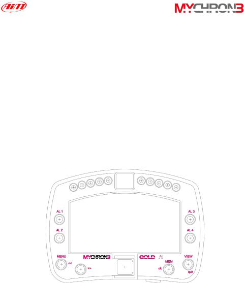
In the following drawing it is represented your MyChron 3 Gold display unit: in the middle of the picture it is visible the wide display, in the lower part there is the keyboard, on the left and on the right there are 4 coloured alarm led (labelled from AL.1 to AL4) and, in the upper part, you can find the gear number display and 10 fully configurable RPM led.
In the following pages it will be described the different parts of MyChron 3 Plus/Gold/Gold XG system.
5
|
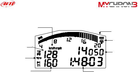
The Display |
|
Speed measure |
Low battery |
|
unit |
||
|
warning |
|
|
Night Vision |
|
Channels #2 and |
Configurable |
|
#4 |
||
display: RPM, |
||
|
||
Temperature |
speed, battery |
|
voltage |
||
measure unit |
||
|
||
Channels #1 and |
|
|
#3 |
Lap (split) time |
The wide display with backlight shows RPM (graphical bar), temperature and pressure analog inputs, test and lap number and, when the vehicle passes in front of the beacon, it shows the Lap Time (or Split Time). It is also possible to configure a second display page (using button VIEW) in order to see the RPM digital value (as shown in the previous drawing), the vehicle speed (in km/h or Mph) or the best lap time. When you are not running it is also possible to see the battery voltage.
The display also shows some small icons, showing the configured Temperature unit of measure (Celsius [°C] or Fahrenheit [°F]), the Speed unit of measure (km/h or Mph), the current displayed measure (P1 → P4 for pressures, T1 → T2 for temperatures, 1 → 4 for custom sensors) the backlight option and the Low Battery Warning, that appears when the battery voltage is low.
6
|
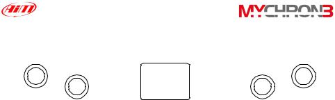
The Keyboard |
|
MENU |
|
VIEW |
<< |
|
MEM |
>> |
USB |
ok |
|
||
|
|
quit |
The Keyboard is composed of four push-buttons and it is used to configure the instrument, to recall recorded data and to clear the internal memory.
The four pushbuttons are used for:
MENU/<< Used to enter configuration mode and to switch to previous configuration option; also used to turn on/off backlight during a test.
>>Used in configuration to switch to next option; also used to switch
between the 4 analog inputs (temperatures and pressures). MEM/OK Used to confirm a configuration, to retrieve recorded data and to
see the best lap time.
VIEW Used to exit configuration mode without saving, or to switch the display from “digital RPM” value to “battery voltage”, to “best lap time” or to “vehicle speed”.
The gauge automatically switches ON/OFF when the user switches on/off the car’s (bike’s) electric switchboard.
To run the system in DEMO MODE, while holding down button MENU/<< and >>, press button VIEW.
In the middle of the keyboard, protected by a plastic cover, it is located the instrument’s USB port (used to connect the instrument to a PC).
7
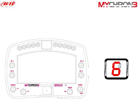
The alarm led and the gear display
In the following picture it is reported a drawing of MyChron 3 Gold Car display unit.
•The alarm led are placed on the left and right of the main display: on the left there are the led 1 and 2 and, on the right, there are the led 3 and 4. The four led are red colored.
•The RPM led are placed in the display unit upper part: this fully configurable led turn on two-by-two, advising the driver to shift gear. The 4 external led (2 on the left and 2 on the right) are green colored, the 2 middle ones are orange colored and the 4 remaining ones are red colored.
•The Gear display is placed in the middle of the RPM led. This digital display shows the current gear number; the instrument is able to display up to 9 gears.
8
The Speed sensor for CAR installations
MyChron 3 Plus/Gold/Gold XG is equipped with a speed sensor, which allows the pilot to measure vehicle’s speed.
The wheel speed sensor for gear tooth belongs to the “non contact” devices and it needs a ferrous metal trigger to pass the sensor face.
The instrument’s measure range is included between 0.5 and 2 mm: the optimum sensing distance is 1 mm.
Optimum sensor performance is dependent on the following variables, which must be considered in combination: trigger material, geometry and speed, sensor trigger gap, magnetic material in close proximity. Please refer to the “Installing the CAR speed sensor” paragraph for further information.
The speed sensor is supplied with an 80 mm long cable.
In the following drawing you can see the gear tooth speed sensor side view (on the left) and a 3D view (on the right).
9
The Speed sensor for BIKE installations
The wheel speed sensor for bike installations belongs to the “magnetoresistive – non contact” devices and it needs a magnetic metal trigger to pass the sensor face.
The magnetoresistive speed sensor is a high sensing distance instrument: its measure range goes from 8 to 15 mm and the optimum sensing distance is 10 mm.
Please refer to the “Installing the BIKE speed sensor” paragraph for further information.
The speed sensor is supplied with a 1700 mm long cable.
In the following drawing you can see the bike speed sensor and, on the right, the magnetic trigger (supplied together with the sensor).
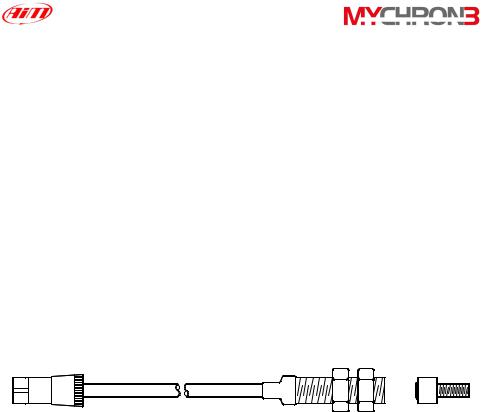
The Temperature sensors
MyChron 3 Plus/Gold/Gold XG supports up to 4 temperature sensors. There are 4 types of temperature sensors that are available for selection or subsequent purchase:
1.H2O - Water thermocouple or thermoresistance: M5 type.
2.EGT - Exhaust gas thermocouple.
3.CHT - Cylinder head thermocouple.
10
1 |
2 |
3 |
All temperature sensors are supplied with a 0.25 m long connection cable. Thermocouple or thermoresistance extension cables are available with lengths included between 0.5 and 2 m and, on request, as specified dimensions.
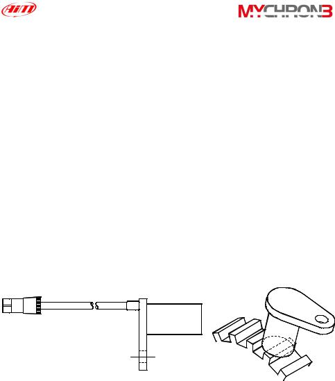
The LAP receiver
The infrared lap receiver is used to recognise a signal, called “lap marker”, emitted from an infrared transmitter (Beacon).
The Infrared receiver has to “see” the transmitter placed on the trackside, so remember to install it with the receiver eye (the grey point in the photo on the left) pointed to the beacon transmitter.
11
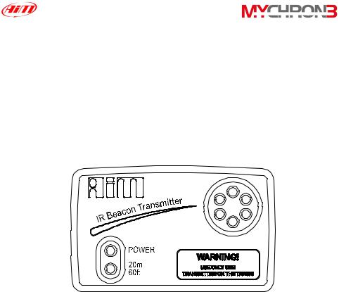
The LAP transmitter (Beacon)
The optical Beacon Transmitter has to be placed on the trackside to mark laps. Ensure the infrared receiver eye faces the side of the track where the Beacon has been placed, otherwise the system will not record lap time.
The Beacon transmitter is powered using 8 AA batteries or an external 12V power cable. If you are using 8 AA batteries, unscrew the back cover of the Beacon transmitter and place the battery pack into the transmitter casing.
The transmitter has two operating modes: Low power and High power. The Low Power Mode has to be used when the track is less than 10 meters wide, while the High Power mode has to be used when the track is wider than 10 meters.
To activate the High/Low Power function, please open the Beacon transmitter with a corkscrew and place the clip (located directly below where the battery pack is attached to the beacon transmitter board) either over one of the two connectors (for low power mode) or over the two connectors (for high power
mode).
12
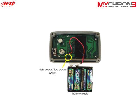
When the Beacon transmitter operates in high power mode, both the power led lights will light up when the transmitter is turned on.
Please, remember that, in High Power Mode, the transmitter has to be powered by an external 12 Volts battery.
13

How to install MyChron 3 Plus/Gold/Gold XG
Now you can start installing your MyChron 3 Plus/Gold/Gold XG on your car/bike.
It is recommended to follow these instructions in order to preserve your instrument and to capture consistent and accurate data.
We remind you that your MyChron 3 Plus/Gold/Gold XG is not equipped with internal batteries, and so it needs to be powered by an external power source (the car / bike battery).
The first installation step consists in mounting the Gauge in your car’s (motorbike’s) cockpit. It is recommended to choose a place where the instrument will not be in contact with oil or fuel, make sure that the gauge is not installed too close to heat sources and protect the instrument from vibrations.
In order to correctly measure the lateral g-force using the internal accelerometer (MyChron 3 Gold only), it is suggested to install the gauge with the display perpendicular to the vehicle’s speed.
Installing MyChron 3 Gold XG
Your MyChron 3 Gold XG is composed of two separate objects (the display unit and the Junction box) connected by a pig-tail cable.
It is recommended to choose a place where both the display unit and the Junction box are not in contact with oil or fuel, make sure that the gauge is not installed too
close to heat sources and protect the instrument from vibrations.
14
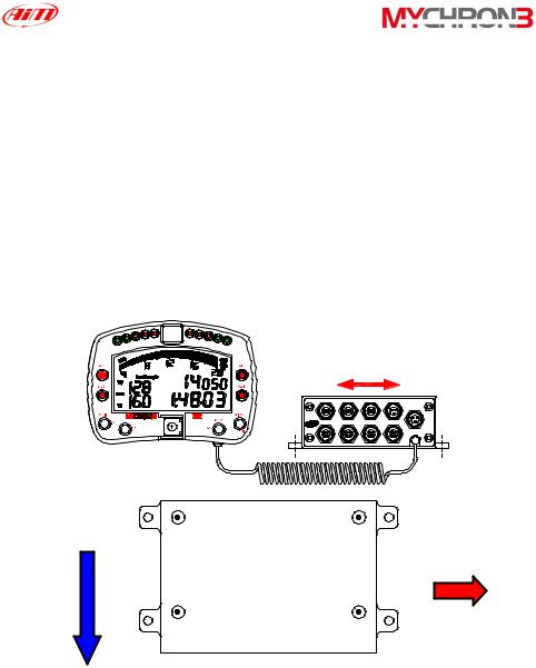
In particular, pay attention when installing the Junction box:
•Avoid rigid connections between the Junction box and the chassis. It is suggested to use anti-vibration mountings (Silent Blocks).
•We remind you that your MyChron 3 Gold XG is not equipped with internal batteries, and so it needs to be powered by an external power source (i.e. the car battery).
•In order to correctly measure the lateral g-force using the lateral accelerometer (mounted inside the Junction box), it is suggested to install the gauge with the Junction box’s front panel perpendicular to the car’s speed, as shown in the following image.
Internal lateral accelerometer
CH1 |
CH3 |
Speed |
Power IN |
|
|
|
RPM |
CH2 |
CH4 |
Beacon |
GEAR |
Speed
direction Lateral Junction accelerometer
Box
15
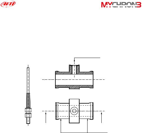
Installing the H2O thermocouple (thermoresistance)
The H2O thermocouple and the thermoresistance can be installed in the inline water fitting (sold separately).
In the following drawing it is represented how to correctly install the water thermocouple (thermoresistance) for the M5 type.
|
The water |
|
thermocouple |
SEZ A - A |
must be |
placed here |
A |
A |
Junction |
|
|
|
Water thermocouple |
|
must be |
|
hanged here |
|
|
|
with two |
|
|
wiring wraps |
Installing the EGT thermocouple
The Exhaust Gas Thermocouple (EGT) should be positioned inside the exhaust header pipe at a distance of 150 mm (5.9 inches) from the exhaust port.
16
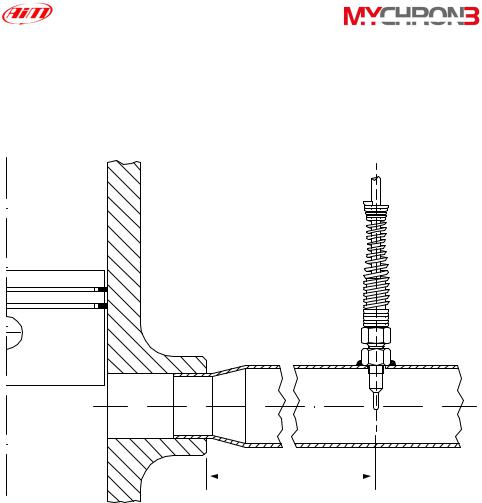
In the following drawing it is represented a correct installation of the EGT thermocouple.
It is recommended that the probe be inserted between 25% and 50% inside the exhaust gas header.
150 mm
To install the EGT thermocouple, please follow these instructions:
1.Make a 5 mm (0.2 inches) hole inside the exhaust header;
2.Weld the little nut to the exhaust header in the place where the hole has been drilled;
17
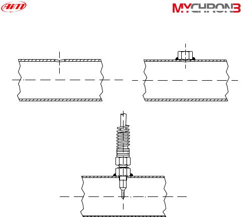
3.Connect the remaining part of the thermocouple and fix it to the exhaust header by screwing it.
1 |
2 |
Weld |
3
Installing the under-spark thermocouple
When using a Cylinder Head Thermocouple (CHT) sensor, always remove the spark plug washer before inserting the spark plug into the sensor.
When tightening and loosening the spark plug, minimise movement of the sensor to avoid damage.
18

In the following drawing it is represented the correct installation of the under-spark thermocouple.
CHT thermocouple
Spark |
Cylinder head |
Installing the “CAR” speed sensor
The wheel speed sensor for phonic wheel belongs to the “non contact” devices and it needs a ferrous metal trigger to pass the sensor face.
When mounting the sensor, please firmly install it on a self-made iron bracket and make sure that the distance between the sensor and the phonic wheel is included between 0.5 and 2 mm (1 mm is the optimum value). Once the sensor has been installed, please plug the sensor’s Binder connector in your MyChron 3 Plus/Gold/Gold XG.
19
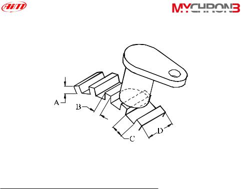
In the following drawing it is reported the speed sensor installation.
In the following table it is reported a short description of the minimum values for the trigger dimensions A, B, C and D required for a correct sensor’s working.
Description |
Value (Minimum) |
|
|
Tooth height (A) |
5.06 mm |
Tooth width (B) |
2.54 mm |
Tooth spacing (C) |
10.16 mm |
Thickness (D) |
6.35 mm |
|
|
In short, optimum sensor performance is dependent on the following variables, which must be considered in combination: trigger material, geometry and speed, sensor trigger gap, magnetic material in close proximity.
20
Installing the “BIKE” speed sensor
The wheel speed sensor for bike installations belongs to the “magnetoresistive – non contact” devices and it needs a magnetic trigger to pass the sensor face. When mounting the sensor, please firmly install it on a self-made iron bracket and make sure that the distance between the sensor and the magnetic trigger is included between 15 and 8 mm (10 mm is the optimum value). Once the sensor has been installed, please plug the sensor’s Binder connector in your MyChron 3 Gold.
How to power the gauge
The gauge must be powered by an external 9-15 VDC power source. Do not exceed these limits.
Connect the red wire to the battery’s positive pole (+) and the black one to the negative pole (-).
How to sample the RPM
The RPM signal may be sampled either from the ECU or from the coil.
•The RPM signal sampled from the ECU is a square wave signal (from 8 up to 50 V);
•The RPM signal sampled from the coil is a high voltage RPM input (from 150 to 400 V) and must not be connected on the “RPM from ECU” input (this event may seriously damage the gauge).
It is also reminded to connect either the RPM signal from the coil or the RPM signal from the ECU, NOT both (this event creates shortcuts).
21

On track
As you power on your MyChron 3 Plus/Gold/Gold XG, some information is displayed: here they are described in the same order as they appear:
1. AIM 1_xy Firmware version.
2. MYC 3 PLUS/GOLD/GOLD XG CAR/BIKE Instrument name.
Configuration functions
Before getting started, please configure your gauge in order to get correct data from your system.
Enter CONFIGURATION MODE (push MENU/<< button) to set the parameters. Buttons MENU/<< (back to previous option) and >> (forward to next option) are used to scroll through the configuration menu.
To exit CONFIGURATION MODE and return to MAIN DISPLAY MODE, press button VIEW.
The parameters you can set in CONFIGURATION MODE are here above explained in the same order they appear by clicking the MENU/<< button.
22

Night Vision |
MyChron 3 Plus/Gold/Gold XG display can be set to |
|
backlight display so that it is visible during night racing. |
|
To set the Night Vision ON or OFF, press button MEM/OK |
|
until you see |
|
NIGHT VISION ON/OFF |
|
and then push button MEM/OK. To return to main display |
|
mode press button VIEW. When the Night Vision option is |
|
activated, a light globe will be displayed in the display’s top |
|
right corner. |
|
To activate Night Vision mode during a test, it is enough to |
|
press button MENU/<<. |
|
The backlight setting is stored by the logger: each time the |
|
logger is switched on, the setting used before switching off |
|
the gauge is automatically restored |
Clear test data The “Clear test data” option clears the data stored in system’s memory.
To run this function, after having entered the CONFIGURATION MODE, push MENU/<< until you see
CLEAR TEST DATA
Then press button MEM/OK twice to erase data or press VIEW to quit.
23
Beacon These 2 functions are fundamental in order to acquire the obscuring correct lap and split time.
time and The first function is used to set the Beacon’s obscuring time, split’s number which is a time period during which the optic receiver, after having acquired the lap marker, is “blind” and can’t detect
other lap markers.
The second function, instead, allows the user to set the track’s split number. In fact, it is possible that a circuit is equipped with more than one Beacon transmitter along the track: additional transmitters than the first one installed on the straight line give “split time”.
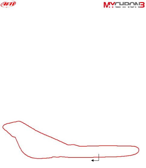
In the following paragraph, it is reported three examples of obscuring time/split’s number configurations.
Example 1) The track is equipped with only one lap transmitter
Start/Finish
Lap time 1’ 25”
24
•In this case you cannot acquire split times because the track is not equipped with additional lap transmitters. It is recommended to set the following values:
o Split’s number = 0;
o Beacon obscuring time: please set a time lower than your best lap time. In this example, the best lap time is 1’ 25”: you should set, for instance, 1’ 10”.
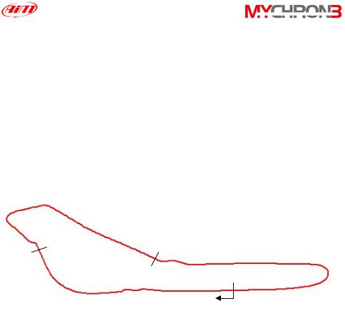
Example 2) The track is equipped with more than one lap transmitter but you do not wish to capture split times
Intermediate 2:
Time 50”
Intermediate 1:
Time 30”
Start/Finish
Lap time 1’ 25”
•As the track is equipped with more than one transmitter and you do not wish to capture split times, please set the following parameters:
o Split’s number = 0;
o Beacon obscuring time: please set a time lower than your best
lap time and greater than the time elapsed at the last
25
intermediate before the finish line. In this example, you should set a value included between 50” and 1’ 25”.
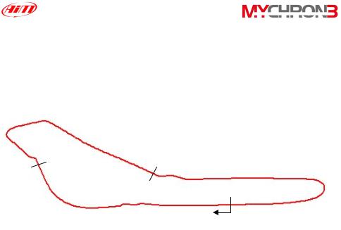
Example 3) The track is equipped with more than one lap transmitter and you wish to capture split times
Intermediate 2:
Time 50”
Intermediate 1:
Time 30”
Start/Finish
Lap time 1’ 25”
•As the track is equipped with more than one transmitter and you wish to capture split times, please set the following parameters:
o Split’s number = total number of lap transmitters installed on the track excluded the one installed on the finish line. In this example, set 2 split’s number.
o Beacon obscuring time: the obscuring time must be lower than the minimum split time. In this example, as the minimum split time elapsed is the one from the first intermediate to the second one (split time 20”), please set the beacon obscuring time to 15”.
26

To set the split’s number, after having entered the CONFIGURATION MODE, push MENU/<< until you see
NUMBER OF SPLITS
Then push MEM/OK to enter EDIT MODE: use button MENU/<< to change numbers and button >> to change digit. The blinking number identifies the digit that can be edited.
Press button MEM/OK to save the changes or button VIEW to discard the changes.
To set the Beacon obscuring time, after having entered the CONFIGURATION MODE, push MENU/<< until you see
Obscuring time
Now push MEM/OK to enter EDIT MODE, then press button MENU/<< until the correct number of splits appears on the display’s lower right corner. The obscuring time can be set up to a maximum value of 100 seconds.
Press button MEM/OK to save the changes or button VIEW to discard the change
Distance and This function shows the total instrument working time (in hours total time and minutes) and the distance covered by the vehicle (in km
or in miles) during a test.
To run this function press button MENU/<< until you see
TOTAL RUNNING
27

|
To delete the total working time and the distance covered by |
|
the vehicle, please press twice button MEM/OK; press VIEW, |
|
instead, if you do not wish to delete these information. |
|
It is reminded that this function computes only time and |
|
distance corresponding to a single test: if you wish to know |
|
the total distance covered by the vehicle, please run function |
|
“Odometer”. |
Odometer |
This function computes the total distance covered by the |
|
vehicle during all the tests made. |
|
To run this function press button MENU/<< till you see |
|
ODOMETER |
|
Unlike the previous function, this parameter cannot be erased. |
Gears |
Your gauge is able both to detect the engaged gear by using |
calibration |
an on-board sensor (for those vehicles equipped with a sensor |
|
installed inside the gearbox) or by calculating them (using an |
|
algorithm based on engine’s RPM and Speed). If no sensor is |
|
installed and the driver does not wish to see the gear number |
|
on the display, the gauge allows the user to disable the gear |
|
channel. |
|
To run this function press button MENU/<< until you see |
|
GEAR CALIBRATION |
|
Press button NEXT/MEM to activate one of the gears |
|
calibration functions here above described: |
|
28 |
Loading...