


MyChron4 660
USER MANUAL

MyChron4 660
User Manual
Release 1.03
INDEX
1 – HOW TO INSTALL MYCHRON4 660 .............................................................. 3
1.1 – How to install and replace the batteries ............................................... 3
1.2 – How to install MyChron4 660 on Junior Dragsters ............................. 5
1.3 – How to install the RPM wire ................................................................... 6
1.4 – How to install the EGT thermocouple ................................................... 7
1.5 – How to install the cylinder head thermocouple ................................... 9
1.6 – How to install the Speed sensor ......................................................... 10
1.7 – How to connect cables to MyChron4 660 ........................................... 13
2 – HOW TO USE MYCHRON4 660 .................................................................... 14
2.1 – The Keyboard ........................................................................................ 14
2.2 – How to switch ON/OFF the gauge ....................................................... 15
2.3 – Configuration functions ....................................................................... 16
2.3.1 – Configuration wizard ....................................................................... 16
2.4 – The Display ............................................................................................ 26
2.5 – Post Run Review ................................................................................... 27
3 – GPS MODULE AND MYCHRON4 660 .......................................................... 31
3.1 - How to connect GPS MODULE ............................................................ 31
Connection with internal power .................................................................. 31
Connection with external power ................................................................. 32
3.2 - How to install GPS module ................................................................... 32
3.3 - Configuration Wizard ............................................................................ 33
3.4 - MyChron4 660 Data visualization ........................................................ 34
3.5 - MyChron4 660 Datakey for data download ......................................... 35
3.6 GPS Module with QMan .......................................................................... 36
4 – MYCHRON4 660 AND THE PC ..................................................................... 38
4.1 – Downloading data with MyChron4 660 ............................................... 38
4.2 – How to use QMAn ................................................................................. 39
4.3 – QMAn installation ................................................................................. 40
4.3.1 – Installation under Microsoft Windows XP™ ................................... 40
4.3.2 – Troubleshooting .............................................................................. 46
4.3.4 – Installation under Microsoft Vista™ ................................................ 47
4.3.5 – Troubleshooting .............................................................................. 54

MyChron4 660
User Manual
Release 1.03
www.aim-sportline.com
2
4.4 – QMAn Data Analysis ............................................................................. 55
4.4.1 – Test/Run manager .......................................................................... 56
4.4.2 – Analysis View.................................................................................. 60
4.4.3 – Time Plot ......................................................................................... 62
4.3.4 – Histogram ....................................................................................... 69
4.3.5 – XY Plot ............................................................................................ 71
4.3.6 – Channel info .................................................................................... 73
4.3.7 – How to set the time slip info ............................................................ 74
4.3.8 – How to set weather station data ..................................................... 75
4.3.9 – Test Loaded View ........................................................................... 76
4.3.10 – Run Info ........................................................................................ 78
4.3.11 – Time Slip ....................................................................................... 79
4.3.12 – Tachometer................................................................................... 80
4.3.13 – Weather ........................................................................................ 81
4.3.14 – How to send the test file via E-mail .............................................. 81
4.5 - Maintenance ........................................................................................... 82
4.5.1– How to upgrade the firmware .......................................................... 82
APPENDIX A: TECHNICAL CHARACTERISTICS ............................................. 84
MyChron4 660
User Manual
Release 1.03
www.aim-sportline.com
3
1 – How to install MyChron4 660
Before installing MyChron4 660, please read these installation instructions
carefully. It is very important that your MyChron4 660 is correctly installed in
order to capture consistent and accurate data. Incorrect installation may result in
system malfunction.
Now you may start installation of MyChron4 660 on your Junior Dragster.
It is recommended to follow these instructions in order to preserve your
instrument and to capture consistent and accurate data.
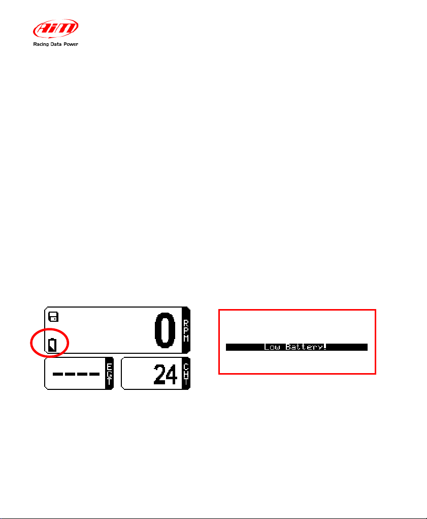
1.1 – How to install and replace the batteries
Your MyChron4 660 is powered by one 9V alkaline battery.
When the internal battery requires replacement, a battery indicator will blink in the
lower left corner of the display:
If you do not replace the battery and keep on running, the system might shut
down during a test. The following screen (above right) will appear a few seconds
before the gauge shuts off .
MyChron4 660
User Manual
Release 1.03
www.aim-sportline.com
4
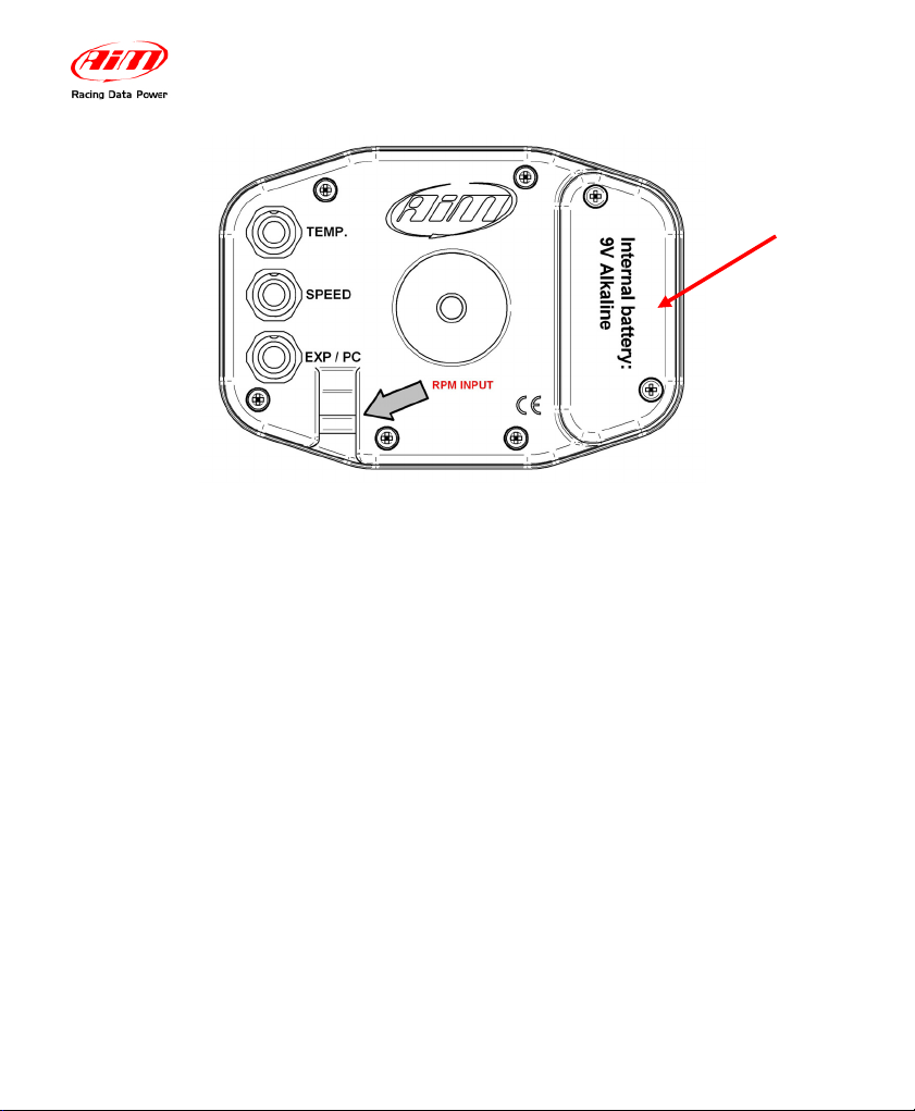
To change battery, remove the two screws on the back of the display unit. A 9V
battery will be connected to a two-wire power lead. Simply disconnect the battery
from the lead and replace with a new battery.
Do not over-tighten the screws when mounting the battery cover to the back
of the display unit.
open here to
change the
battery
MyChron4 660
User Manual
Release 1.03
www.aim-sportline.com
5
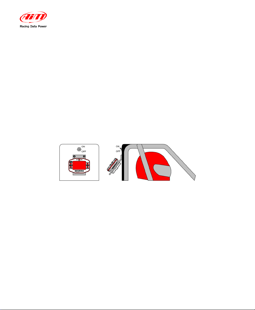
1.2 – How to install MyChron4 660 on Junior Dragsters
One of the main uses of the gauge is to allow the mechanics to set up engine’s
carburetion in the staging area immediately before the race start.
To make this easy, it is suggested to install the gauge in a place where the
mechanics may see the display while working on the engine.
Behind the body cell on the vertical metal bulkhead which separates the racer’s
seat from the engine is a commonly used location. More specifically, as shown in
the following drawing, AIM recommends all MyChron4 660 users to install the
gauge under the engine’s ON/OFF switch.
The gauge has to be mounted on a self-made bracket as shown in figure above.
The bracket has to be made of aluminium or steel, and its thickness must be
0.1 “(2.5 mm) or more in order to have a high stiffness and resist vibration when
the engine is turned on.
Firmly fix the bracket to the vertical metal bulkhead and then fix your MyChron4
660 to the bracket.
Do not over-tighten the 8 mm mounting nut. Over-tightening the nut may cause
damage to the display unit casing.

MyChron4 660
User Manual
Release 1.03
www.aim-sportline.com
6
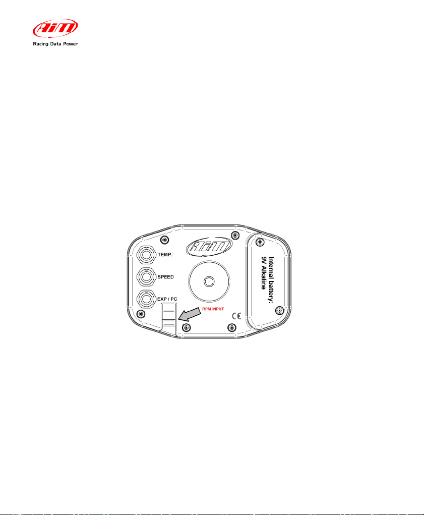
1.3 – How to install the RPM wire
The RPM wire has to be connected to the ON/OFF switch (kill switch). This switch
is usually a 2-poles switch (some switches are a single pole, but most are two):
one pole is COIL, the other one is RPM.
The RPM wire should be going to the coil side of the kill switch. Running it to the
grounded side of the switch causes the RPM signal to drop in and out and
sometimes not to work at all.
Because the ON/OFF switch is mounted on the opposite side of the bulkhead with
respect to the gauge, it is necessary to drill a 0.2” (5 mm) hole inside the
bulkhead.
Remember to insert the rubber wire-holder in order to protect the RPM wire
against tears and cuts.
While connecting the RPM wire to your MyChron4 660, please keep the
cable as far as possible from the temperature ones. If the RPM and
temperature wires are wrapped together, the temperature channels might be
very noisy.
MyChron4 660
User Manual
Release 1.03
www.aim-sportline.com
7
1.4 – How to install the EGT thermocouple
The Exhaust Gas Thermocouple (EGT) has to be installed inside the exhaust
header pipe at a distance of approximately 5.9“ (150 mm) from the exhaust port.
The figure below shows the proper way to install the EGT thermocouple and the
installation wrapper.
It is recommended to insert the sensor between 25% and 50% inside the exhaust
gas header.
To correctly install the EGT thermocouple, please follow these instructions:
1. Make a 0.2” (5 mm) hole inside the exhaust header
2. Fix the metal wrapper to the exhaust header pipe in the hole you have
drilled. It is reminded that the pipe’s hole and the wrapper’s threaded nut
must be coaxial
3. Screw the EGT thermocouple in the wrapper’s nut and firmly fix it. Plug
the thermocouple’s male Mignon connector to the EGT input wire of the
“2 temperatures split cable”.
MyChron4 660
User Manual
Release 1.03
www.aim-sportline.com
8
The EGT thermocouple may also be installed using a steel adapter which has to
be welded to the exhaust header pipe, as described in the following drawing and
explained below.
Make a 0.4” (10 mm) hole inside the exhaust header
1. Weld the EGT adapter inside the hole
2. Screw the EGT thermocouple inside the EGT adapter
3. Plug the thermocouple’s male Mignon connector to the EGT input wire of
the “2 temperatures split cable”.
1
3
2
MyChron4 660
User Manual
Release 1.03
www.aim-sportline.com
9
1.5 – How to install the cylinder head thermocouple
When using a Cylinder Head Thermocouple (CHT) sensor, always remove the
spark plug washer before inserting the spark plug into the sensor.
When tightening and loosening the spark plug, minimise movement of the sensor
to avoid damage.
The figure below shows how to correctly install the CHT sensor.
Once the sensor has been correctly installed, plug the thermocouple’s male
Mignon connector to the CHT input wire of the “2 temperatures split cable”.
MyChron4 660
User Manual
Release 1.03
www.aim-sportline.com
10
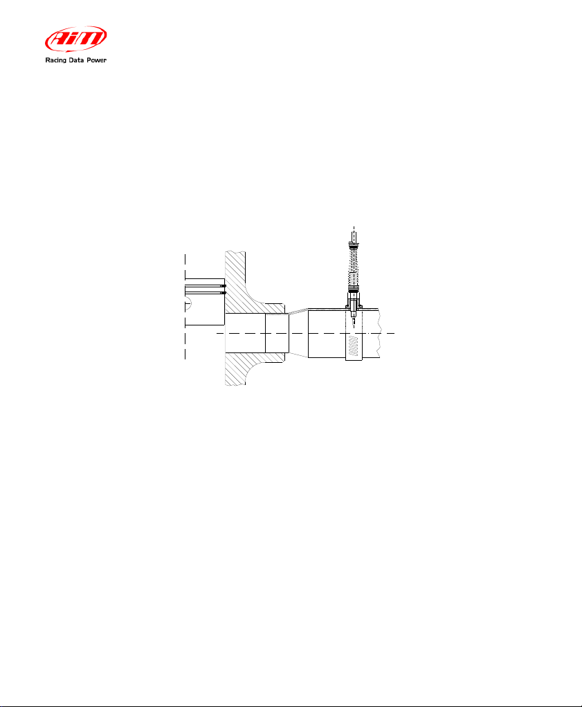
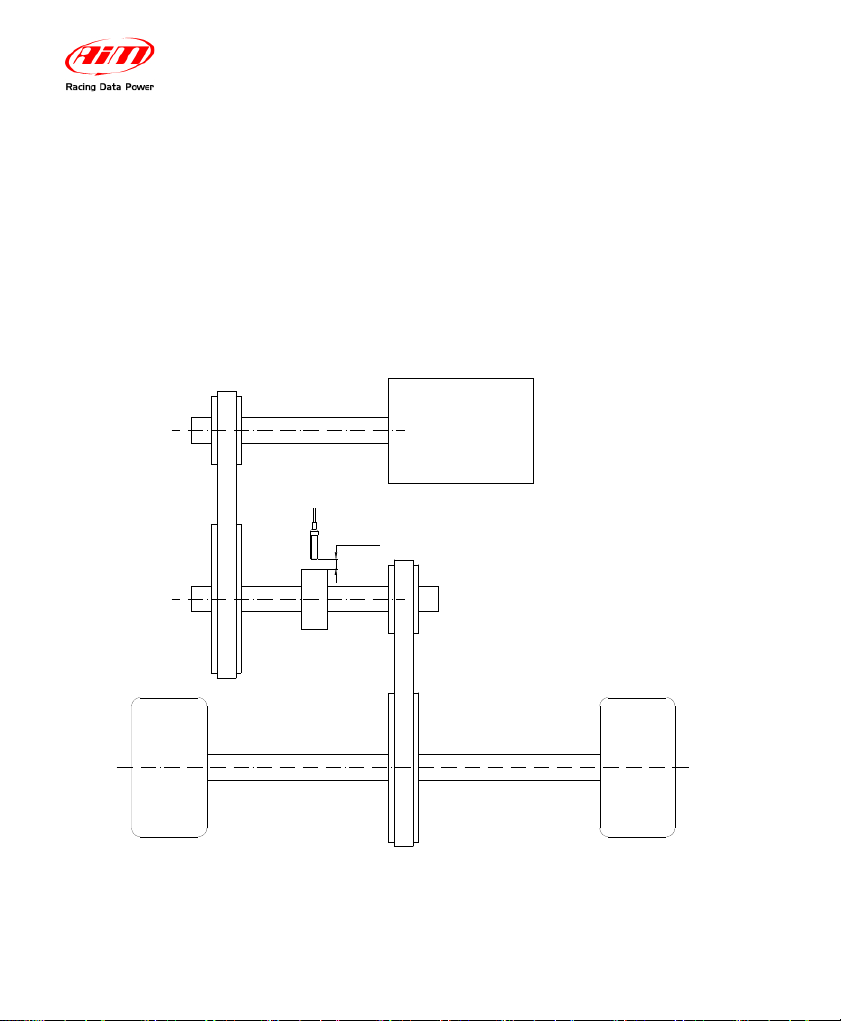
1.6 – How to install the Speed sensor
In order to sample the dragster’s speed, you have to install a phonic wheel
(jackshaft collar) on the jackshaft (¾” diameter) moved by the clutch. The
movement of the jackshaft and the movement of the wheel are related to the
crown/pinion ratio. An installation layout of the speed sensor and magnetic phonic
wheel is shown in the figure below.
Primary V-type belt drive
Rear wheel Rear wheel
Secondary chain drive
Phonic wheel
Sensing distance 4 - 8 mm [0.15 - 0.3 "]
Rear axleRear axle
Magnetoresistive speed sensor
ENGINE
MyChron4 660
User Manual
Release 1.03
www.aim-sportline.com
11
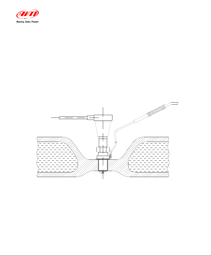
The speed kit is composed of 1 phonic wheel and 1 magneto resistive speed
sensor.
The phonic wheel is made of Teflon and is composed of two separate parts: an
internal ring, which includes 4 magnets, and an external bushing, which protects
the internal ring. The external bushing is fixed to the internal one using 2 hex-key
screws. The magneto resistive speed sensor is composed of a sensing end,
included inside the brass threaded cylinder, and of a 10” (250 mm) long cable to
be plugged into the gauge’s SPEED input.
speed
input

MyChron4 660
User Manual
Release 1.03
www.aim-sportline.com
12
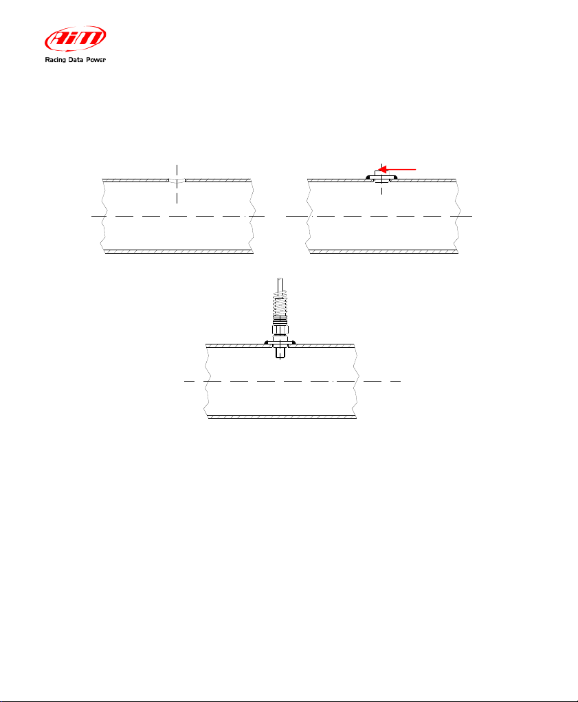
To correctly install the speed kit, please follow these instructions:
1. To mount the phonic wheel on the jackshaft, please remove the pinion
and insert the phonic wheel (internal diameter ¾”) on the jackshaft
2. Fix the phonic wheel to the jackshaft by screwing the M5 locknut (use the
hex key supplied with the kit)
3. Install the magneto resistive speed sensor on a self-made bracket. It is
reminded that the
sensing distance (i.e. the distance between the sensor
and the phonic wheel)
must be 0.15 – 0.3” (4 - 8 mm)
Plug the speed sensor’s male connector into the gauge’s SPEED input
MyChron4 660
User Manual
Release 1.03
www.aim-sportline.com
13
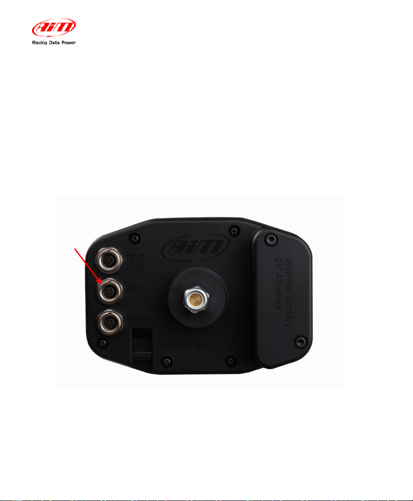
1.7 – How to connect cables to MyChron4 660
Once you have correctly installed all the sensors described above, you need to
connect them to your MyChron4 660. On the backside of the display unit you
have to plug the “2 temperatures split cable” to the connector labelled as
“TEMPERATURE” and the speed cable to the connector labelled as “SPEED”.
The EXP/PC connector is for Lambda, e-Box, data download purposes other CAN
Expansion accessories. The RPM wire is to be placed inside the two holes to the
bottom right of the EXP/PC connector as shown in the figure below.
While connecting the cables to the main display unit, it is strongly
recommended to keep the RPM wire separated from the thermocouple wires
in order to minimize any interference there may be between cables.
MyChron4 660
User Manual
Release 1.03
www.aim-sportline.com
14
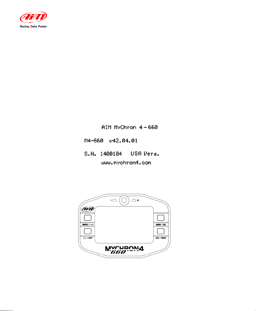
2 – How to use MyChron4 660
As you power on your MyChron4 660, the display shows the following information
(described in the same order as they appear):
1. AIM MYCHRON4 660 Instrument name
2. V42.04.01 Firmware version.
3. S.N.XXXXXXXX Serial number
2.1 – The Keyboard

MyChron4 660
User Manual
Release 1.03
www.aim-sportline.com
15
The Keyboard is composed of four rubber push-buttons and is used to turn the
gauge ON and OFF, configure the system, recall recorded data from memory and
to clear the internal memory.
The four push-buttons are used to perform the following functions :
MENU/<<
Used to enter configuration mode, to switch to the previous
configuration option and to turn on backlight during a test.
>>/OFF
Used to switch to the next configuration option, to enter Check
mode and to switch the gauge OFF
MEM / OK
Used to CONFIRM a configuration and to retrieve recorded data.
ON/VIEW
Used to switch ON the gauge, to exit configuration menu, or to
switch the display from “RPM digital value” to “Current time”.
2.2 – How to switch ON/OFF the gauge
If you wish to switch ON the gauge, press button ON/VIEW, if you wish to switch
it OFF, keep >>/OFF pressed.
Your MyChron4 660 has an automatic power down feature that turns the power
off after 10 minutes of inactivity.
To run the system in DEMO MODE, switch it on by pressing button
ON/VIEW, then hold down MENU/<< and >>/OFF buttons for a couple of
seconds.

MyChron4 660
User Manual
Release 1.03
www.aim-sportline.com
16
2.3 – Configuration functions
Before starting your system on-track, please configure your gauge in order
to acquire correct data from your system.
2.3.1 – Configuration wizard
You can enter the Configuration Menu pressing the MENU button.
The Wizard automatically switches on every time you enter the configuration
menu, until it ‘s fully completed at least once.
Following the Wizard steps, you need to configure:
•
Temperature Unit ( Fahrenheit or Celsius)
•
Maximum RPM (Bar Graph Maximum RPM)
•
RPM Tattle ( 0 = disabled)
•
Wheel Circumfrence (inch)
• Drivegear
• Drivengear
Adjust Hour
Adjust Minute
Adjust Year
Adjust Month
Adjust Day of Week
The points listed here above are quite intuitive and do not need further
explanations;

MyChron4 660
User Manual
Release 1.03
www.aim-sportline.com
17
Your configuration Wizard has now finished and your MyChron4 660 is ready to
start running.
Explanation about the configuration can be found in the Configuration Menu
paragraph below.

MyChron4 660
User Manual
Release 1.03
www.aim-sportline.com
18
Manual configuration
Please, switch ON the gauge (press ON/VIEW) and enter Configuration Mode
(push MENU/<< button) in order to set the configuration parameters (RPM scale,
RPM factor, Wheel circumference, etc…).
Buttons MENU/<< (back to previous option) and >>/OFF (forward to next option)
are used to scroll through the configuration menu.
To exit Configuration Mode and return to Main Display Mode, press ON/VIEW.
The parameters you may set in Configuration Mode are explained here below in
the same order they appear when you scroll through them by pressing the
>>/OFF button.
MyChron4 660
User Manual
Release 1.03
www.aim-sportline.com
19
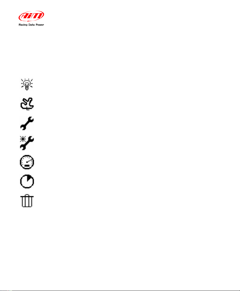
Configuration Menu
The Configuration Menu can be activated pressing MENU button. Once you have
completed the configuration Wizard at least once, the MENU screen appears as
in the picture here below:
BackLight
Track Name
Control Panel
Configuration Wizard
Speed Setup
Engine Pass Counter
Clear Test Data
MyChron4 660
User Manual
Release 1.03
www.aim-sportline.com
20
The gauge’s display can be set to backlight display so that it
is visible during night racing or in low-visibility conditions.
To set the Night Vision ON or OFF, highlight backlight icon
and press MEM/OK:
Backlight
(Night Vision)
The Track Name is associated with every run recorded on your
MyChron4 660. This is extremely useful when you have many
runs, in order to understand when and where your data have been
recorded. The Track Name is also managed by our
RaceStudio2
Software, when you download your data on the PC.
You can fill in the name of the tracks in which you normally
race, and then select the current track among them
Track Name
This section will be analyzed later.
Control Panel
Through this function you get back to the beginning of the
configuration, when the logger asks you again to go ahead
with the configuration process as in the first time.
Configuration
Wizard

MyChron4 660
User Manual
Release 1.03
www.aim-sportline.com
21
Speed Setup function sets these parameters:
Wheel circumference: this function allows to set the wheel
circumference in inches. This parameter is fundamental to
correlate the wheel angular speed and the dragster speed.
To run this function select ‘Speed Setup’ and press MEM/OK.
Push MEM/OK to enter edit mode: use menu/<< or >>/OFF
to increase/decrease wheel circumference (¼” steps).
When the correct circumference value has been set, press
MEM/OK to save or ON/VIEW to quit without saving.
Drive gear (pinion) teeth number: select the second line;
push MEM/OK to enter edit mode: use menu/<< or >>/OFF
to increase/decrease teeth number.
The pinion teeth number value can be set in a range included
between a minimum value of 5 and a maximum value of 49.
When the correct number of teeth has been set, press
MEM/OK to save or ON/VIEW to quit without saving.
Driven gear (crown) teeth number: select the third line,
push MEM/OK to enter edit mode: use MENU/<< or >>/OFF
to increase or decrease the number of teeth.
The crown teeth number value can be set in a range between
a minimum value of 5 and a maximum value of 199. Once
set, press MEM/OK to save or ON/VIEW to quit.
Speed Setup

MyChron4 660
User Manual
Release 1.03
www.aim-sportline.com
22
The MyChron4 660 includes an internal run-counter which
lets the user know the number of runs the gauge has
recorded
The date shown in the function name represents the engine
pass when you erased the run-counter.
To run this function, after having entered the configuration
mode press the MENU/<< button until the following text is
displayed: Engine Pass Counter. Then press the MEM/OK
button twice to erase the run-counter or press ON/VIEW to
discard changes.
In the first channel you can visualize the total number test in
order to monitor the activity of your engines.
Engine Pass
Counter
The “Clear test data” option clears the data stored in the
gauge’s memory.
To run this function, press MENU/<<, place the highlight
selector on the Clear Test Data Icon (Trashcan Icon) by
pressing MENU/<< or >>/OFF and press the MEM/OK
button. A “Confirm Clear” screen will appear. Press MEM/OK
once more to confirm the clear data process or press
ON/VIEW to get back to the previous menu page without
clearing data.
Clear Test
Data

MyChron4 660
User Manual
Release 1.03
www.aim-sportline.com
23
Now we will take a look at the Control Panel sub-menu.
This function sets the maximum scale for the RPM display
and the maximum acceptable RPM value sampled by your
MyChron4 660.
MyChron4 660 can be configured to manage a wide range
of RPM (from 8,000 to 16,000). Please remember to insert a
higher value than your Engine’s Maximum RPM to acquire
correct data.
To run this function, press the MENU/<< button, place the
highlight selector on the Control Panel Icon (upper Wrench
Icon) by pressing MENU/<< or >>/OFF to scroll, and press
the MEM/OK button. Select the RPM Setup Icon and press
MEM/OK. Select the Maximum RPM option, and press
MEM/OK to enter the Maximum RPM setup. You can
increase or decrease RPM value by pressing MENU/<< or
>>/OFF. Then press MEM/OK to confirm or ON/VIEW to
discard changes and get back to the previous menu.
RPM Setup
The temperature setup menu will allow you to switch
temperature units or to set the Alarm.
• Change the Temperature Unit between Fahrenheit (°F)
and Celsius (C°)
• TEMP EGT ALARM (Lower Value) -Range: OFF- 1000
Temperature
Setup

MyChron4 660
User Manual
Release 1.03
www.aim-sportline.com
24
• TEMP CHT ALARM (Lower Value).-Range :OFF- 400
Select the key , press MEM/OK and use “>>” and “<<” button
to configure the alarm threshold.
Then press again MEM/OK to stored the changes or
ON/VIEW to discard them.
The system setup menu sets different options of the system:
• Set Time/Date: your MyChron4 660 is equipped
with an internal clock which allows the user to see
the current date and time on the display.
Moreover, this information is saved inside the test
file in order to time and date stamp every run you
make. To run this function, press the MENU/<<
button, highlight the Control Panel Icon (upper
Wrench Icon) by pressing MENU/<< or >>/OFF to
scroll and press the MEM/OK button. Select the
System Setup Icon and press MEM/OK. Select
the Set Time/Date, and press MEM/OK. You can
increase or decrease time values by pressing
MENU/<< or >>/OFF. When done, press
MEM/OK to confirm or ON/VIEW to discard
changes and get back to the previous menu.
The internal clock is powered by one 9V alkaline
System setup

MyChron4 660
User Manual
Release 1.03
www.aim-sportline.com
25
battery: if battery is removed from the battery pack
for more than 60 seconds (approximately) you will
have to set date and time again.
• Reverse: Use Reverse to switch display dots from
white to black and vice-versa.
• System information: this function shows:
firmware version and gauge serial number.
To run this function, press the MENU/<< button,
highlight the Control Panel Icon (upper Wrench
Icon) by pressing MENU/<< or >>/OFF and press
the MEM/OK button. Select the System Setup
Icon and press MEM/OK. Select the System
Information option, and press MEM/OK to view
Firmware Version. Press ON/VIEW to get back to
the previous menu.
This function sets the driver’s name. This information is
saved inside the test file in order to name every run you
make. Save the settings by selecting the disk icon.
Driver
This function allows you to change the language in your
gauge. There are 2 options: English and Spanish
Language
MyChron4 660
User Manual
Release 1.03
www.aim-sportline.com
26
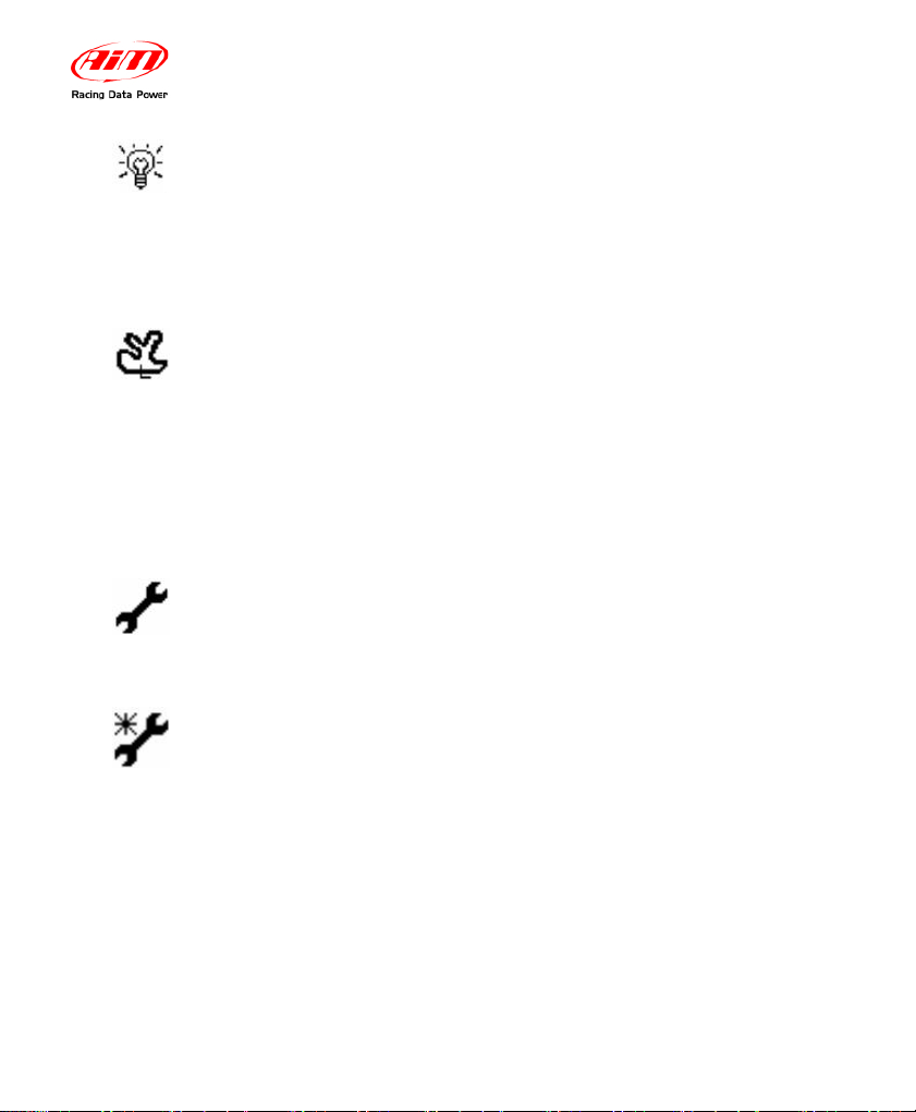
2.4 – The Display
The wide display with backlight shows information such as RPM (digital value),
cylinder head temperature CHT (lower right corner of the display) and exhaust
gas temperature EGT (lower left corner)
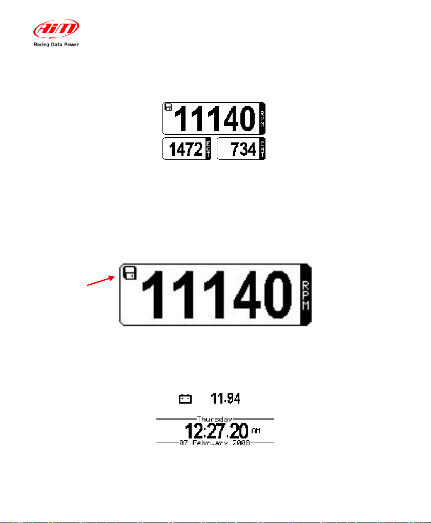
When the disc icon appears in the upper left hand corner, the system has begun
recording data.
Pressing ON/VIEW button again will show the battery voltage status and the
calendar. Please refer to Set Date and Time paragraph for further info about
setting calendar values.
The system is
recording
 Loading...