


MXL
USER MANUAL

MXL
User manual
Release 1.24
MXL, with all its versions (Strada, Pista, Pro, Pro05) belongs to the new generation of AIM data acquisition systems for car/bike races.
Equipped with a beautiful and wide display, easy to use, multi-functional and fully configurable, it fits any need and can record in detail driver’s and vehicle performances.
MXL is part of AIM Total Racing Solution, that includes also Race Studio 2 software to configure the logger and download its data.
MXL allows to monitor and show RPM, speed, engaged gear, lap/split times and data sampled by other custom sensors.
MXL has also a backlight, very useful during night races or in low light conditions.
Moreover, thanks to the lateral g-sensor or to the external gyroscope it is possible to create the track map to relate sampled data to the position on the track.
Always versatile, MXL is available with different non volatile internal RAM memory dimensions: 128kb (Strada), 8Mb (Pista/PRO) or 16Mb (PRO 05). The memory is saved also when the logger is switched off.
The logger has a lateral USB port used to connect it to a PC. Thanks to MemoryKey, moreover, it is possible to download data with no need of a PC on the track.
MXL is a modular system that, using the CAN bus, can increase every day its potentialities. It is possible to connect it not only to a series of channels multipliers (Data Hub, TC Hub, etc), but also to a Lambda Controller, to the GPS Module with lap timer function as well as to a Video system (DaVid).
Warning: any documentation mentioned in this user manual can be freely downloaded from AIM corporate website at www.aim-sportline.com.
www.aim-sportline.com |
1 |

|
|
MXL |
|
|
User manual |
|
|
Release 1.24 |
|
INDEX |
|
1 – MXL kits, optional and part numbers................................................................ |
3 |
|
1.1 |
– MXL Strada kit, optional and part numbers ........................................................................ |
3 |
1.2 |
– MXL Pista kit, optional and part numbers ........................................................................... |
4 |
1.3 |
– MXL Pro05 kit, optional and part numbers.......................................................................... |
5 |
1.4 |
– MXL Expansions .................................................................................................................... |
6 |
2 – MXL installation and power ............................................................................... |
7 |
|
2.1 |
– How to install MXL ................................................................................................................. |
7 |
2.2 |
– How to power MXL................................................................................................................. |
7 |
|
2.2.1 – the GND.......................................................................................................................... |
8 |
2.3 |
– How to connect MXL to the ECU .......................................................................................... |
9 |
2.4 |
– How to sample the RPM signal........................................................................................... |
10 |
|
2.4.1 – Sampling the RPM via CAN bus/RS232 ...................................................................... |
10 |
|
2.4.2 – Pre-condition to sample the RPM in another way ........................................................ |
10 |
|
2.4.3 – Sampling the RPM from the ECU through a square wave signal ................................ |
10 |
|
2.4.4 – Sampling the RPM from the coil: low voltage RPM input............................................. |
11 |
2.5 |
– How to connect MXL analog channels .............................................................................. |
12 |
2.6 |
– How to install and power transmitter and receiver .......................................................... |
13 |
|
2.6.1 – Infrared transmitters ..................................................................................................... |
13 |
|
2.6.2 – The infrared transmitter ................................................................................................ |
15 |
2.7 |
– How to connect MXL to the GPS Module .......................................................................... |
16 |
|
2.7.1 – GPS Module and the Lap timer function ...................................................................... |
17 |
|
2.7.2 – GPS Manager Software................................................................................................ |
17 |
2.8 |
– How to connect MXL to the MemoryKey ........................................................................... |
18 |
3 – MXL display....................................................................................................... |
19 |
|
3.1 |
– Forecast Lap time ................................................................................................................ |
20 |
3.2 |
– Alarm led and shift light ...................................................................................................... |
21 |
3.3 |
– Other useful information ..................................................................................................... |
21 |
4 – MXL: software, driver, configuration, transmission, download, online, |
||
maintenance............................................................................................................ |
22 |
|
5 – MXL keyboard function.................................................................................... |
23 |
|
5.1 |
– Data recall............................................................................................................................. |
23 |
5.2 |
– Other keyboard functions ................................................................................................... |
25 |
|
5.2.1 – Backlight ....................................................................................................................... |
25 |
|
5.2.2 – Setting GPS lap timer laps and splits ........................................................................... |
25 |
|
5.2.3 – Total running................................................................................................................. |
25 |
|
5.2.3 – Odometer (not resettable) ............................................................................................ |
25 |
|
5.2.4 – Date and time ............................................................................................................... |
26 |
|
5.2.5 – Shift lights ..................................................................................................................... |
26 |
|
5.2.6 – System Information....................................................................................................... |
27 |
|
5.2.7 – Demo mode .................................................................................................................. |
27 |
6 – MXL memory ..................................................................................................... |
28 |
|
6.1 |
– Memory architecture: .......................................................................................................... |
28 |
6.2 |
– Memory working way........................................................................................................... |
28 |
Appendix “A” – Technical drawings..................................................................... |
29 |
|
A.1 – Loggers pinout .................................................................................................................... |
29 |
|
A.2 – MXL Strada/Pista wirings ................................................................................................... |
33 |
|
A.3 – MXL Pro05 wirings .............................................................................................................. |
37 |
|
A.4 – USB Cable ............................................................................................................................ |
44 |
|
www.aim-sportline.com |
2 |
MXL
User manual
Release 1.24
1 – MXL kits, optional and part numbers
AIM developed different MXL kits to fit any situation. Here below a description of each standard kit with the related optionals.
Warning: MXL Pro is out of production, replaced by MXL Pro05.
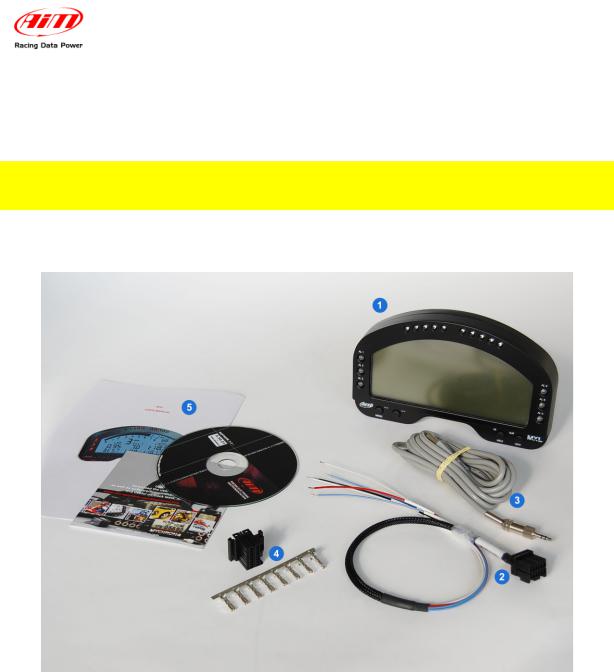
1.1 – MXL Strada kit, optional and part numbers
MXL Strada standard kit: X10MXLS00000
•MXL Strada (1);
•Power and ECU CAN/RS232 interface cable (2);
•USB cable for PC interface (3);
•AMP 16 pins connector (4)
•Race Studio 2 software CD and MXL User manual (5).
MXL Strada Optional:
•Kit basic sensors (RPM, speed, water temp.) + wiring: X10MXLKS00000;
•Infrared receiver with 90 cable: X41RX12090;
•Infrared lap transmitter: X02TXKMA01;
•Expansions (see related paragraph).
www.aim-sportline.com |
3 |
MXL
User manual
Release 1.24
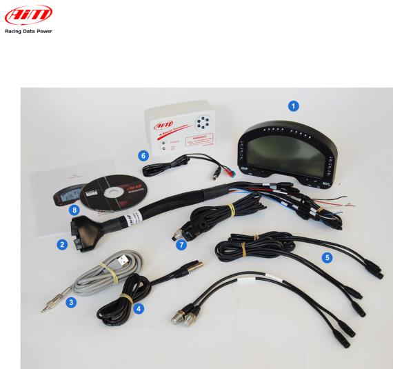
1.2 – MXL Pista kit, optional and part numbers
MXL Pista standard kit: X10MXLC000000
•MXL Pista (1);
•Complete wiring with power, RPM signal and ECU CAN/RS232 interface (2);
•USB cable for PC interface and data download (3);
•1 speed sensor + cable (4);
•2 temperature sensors + cable (5);
•Infrared lap transmitter with external power cable (6);
•Infrared receiver with 90 cm cable (7);
•Race Studio 2 Software CD and MXL user manual (8).
MXL Pista optionals:
• Expansions (see related paragraph).
www.aim-sportline.com |
4 |
MXL
User manual
Release 1.24
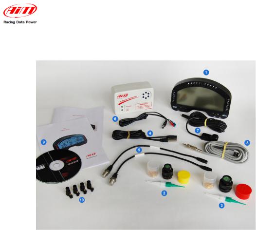
1.3 – MXL Pro05 kit, optional and part numbers
MXL Pro05 standard kit: X15MXLP000000
•MXL Pro05 (1);
•one 22 pins not cabled Deutsch type connector (2);
•one 37 pins not cabled Deutsch type connector (3);
•1 speed sensor with cable (4) + 4 pins Binder 712 female connector (10) to be chosen among:
o car speed sensor;
o bike speed sensor (in the figure here above); o Contrinex speed sensor;
•2 temperature sensors + cable;
•1 RPM sensor with cable (5) to be chosen among:
o M5 thermo resistor + 4 pins Binder 712 female connector (10); o M10 thermo resistor + 4 pins Binder 712 female connector (10);
o1/8 NPT thermo resistor (in the figure here above) + 4 pins Binder 712 female connector;
o exhaust gas thermocouple + mignon female connector
oM10 water temperature thermocouple + mignon female connector;
•infrared lap transmitter with external power cable (6);
•infrared lap receiver with 90 cm cable (7);
•USB cable for PC interface and data download (8);
•Race Studio 2 software CD MXL user manual and MXL Pro05 pinout (9);
MXL Pro05 Optional:
•Wiring for 22 pins Deutsch type connector: V02554240;
•Wiring for 37 pins Deutsch type connector: V02554200;
•Expansions (see related paragraph).
www.aim-sportline.com |
5 |

MXL
User manual
Release 1.24
1.4 – MXL Expansions
• |
Channel expansion |
X08CHEXUC |
• Data Hub with 40 cm cable: |
X08HUB010 |
|
• Data Hub with150 cm cable: |
X08HUB150 |
|
• |
DaVid Slave Expansion: |
X01DVMKSE000 |
• DaVid Slave Expansion cameras PAL protocol: |
X01CAMPAL |
|
• |
LCU-ONE CAN: |
X08LCU03K0 |
• |
LCU-ONE CAN+Analog |
X08LCUKAOCRS |
• MemoryKey (except for MXL Strada): |
X50MEPC00 |
|
• GPS 05 Module with 130 cm cable: |
X40GPS5B130 |
|
• GPS 05 Module with 400 cm cable: |
X40GPS5B400 |
|
• |
TC Hub (CAN): |
X08UTCCTC |
Please visit www.aim-sportline.com for further information concerning expansions and/or to download the documentation.
Warning: connect all expansions do MXL OFF.
www.aim-sportline.com |
6 |
MXL
User manual
Release 1.24
2 – MXL installation and power
2.1 – How to install MXL
To install MXL follow these instructions:
•choose a place where the display is not in contact with oil or fuel.
•be sure that the logger is not installed close to heat sources.
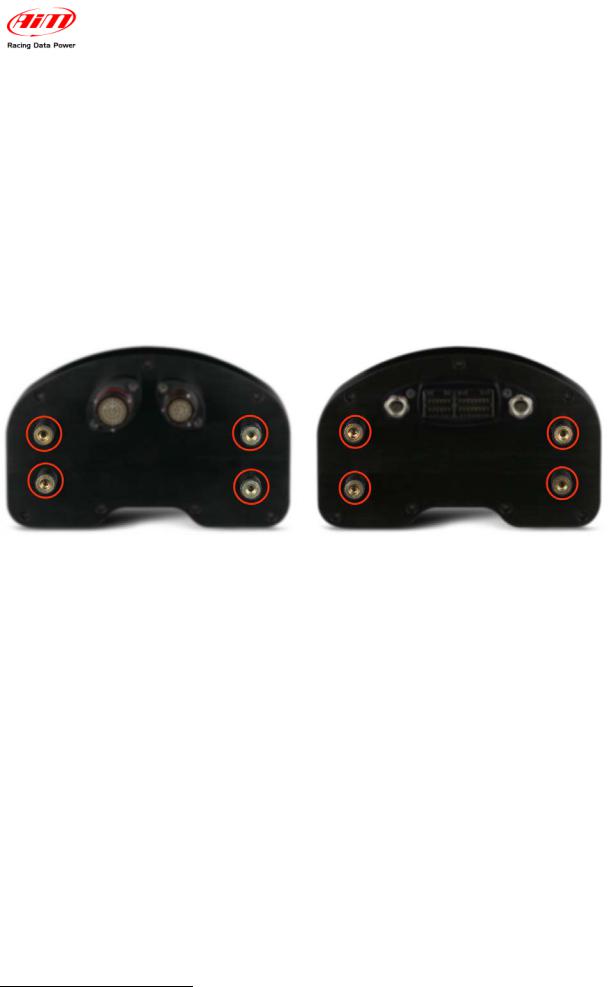
•to correctly measure lateral acceleration through the internal accelerometer1 install MXL vertically and with the display perpendicular to the vehicle speed;
•avoid rigid connections between the logger display and the vehicle chassis and protect the logger from vibrations using the stock anti-vibration mountings highlighted in the images below.
2.2 – How to power MXL
To power MXL:
•connect the logger to an external 9-15 VDC power source (the vehicle battery for example). Warning: do not exceed these limits.
•connect the red cable to the battery positive pole (+) and the black cable to the battery negative pole (-).
To save the battery charge it is suggested to power MXL through the vehicle master switch.
1 Included in the standard kit except for MXL Strada that does not support it.
www.aim-sportline.com |
7 |

MXL
User manual
Release 1.24
2.2.1 – the GND
For a correct powering and signal stability it is suggested to connect the cable labelled GND out coming from MXL power wiring to the vehicle chassis earth.
www.aim-sportline.com |
8 |

MXL
User manual
Release 1.24
2.3 – How to connect MXL to the ECU
MXL can sample data out coming from the ECU using the proper CAN/RS232 interface cable.
To know if the vehicle ECU is supported by MXL – and for further information concerning ECU and AIM loggers connection – refer to the related documentation freely downloadable from AIM corporate website at www.aim-sportline.com download area, ECU section.
In case the conversion of non-standard CAN or RS232 lines is needed, contact our technical support.
It is suggested to always refer to the ECU user manual for any further information concerning pins and cables connection. Moreover – considering that ECU manufacturers constantly improve their products – refer to their websites for more updated information.
To connect MXL to the ECU use a serial RS232 or a CAN cable and connect it to the corresponding non cabled wirings of the logger wiring.
In case an AIM wiring is used all cable are labelled, otherwise it is necessary to identify the cables.
www.aim-sportline.com |
9 |
MXL
User manual
Release 1.24
2.4 – How to sample the RPM signal
MXL can sample the RPM signal in different ways:
•from the ECU via CAN bus or RS232;
•from the ECU through a square wave signal (from 8 to 50 V);
•from the coil: low voltage input (from 150 o 450 V).
2.4.1 – Sampling the RPM via CAN bus/RS232
To sample RPM via CAN bus/RS232 refer to ECU connection chapter.
2.4.2 – Pre-condition to sample the RPM in another way
To sample RPM signal from the ECU through a square wave signal or through the coil it is necessary:
•MXL Strada + kit basic sensors (optional – part number X10MXLKS00000; draw code 04.554.02);
•MXL Pista standard kit;
•MXL Pro05 + 22 pins Deutsch type connector wiring (optional – part number
V02554540; draw code 04.554.24) + 37 pins Deutsch type connector wiring (optional – part number V02554240; draw code 04.554.20).
2.4.3 – Sampling the RPM from the ECU through a square wave signal
To sample the RPM from the ECU using a square wave, connect:
•the white cable labelled “RPM” (MXL Strada/Pista) of the logger wiring to the
ECU RPM signal;
•the blue cable labelled “RPM 8-50 V” of the 37 pins Deutsch type connector wiring (MXL Pro05) to the ECU RPM signal.
Always refer to the ECU user manual for further information. In case ECU output signal is not a steady square wave, an RPM adaptor (optional) is needed. To connect the filter, follow this procedure.
•Connect the blue cable labelled “RPM form” to the cable labelled “RPM” of
MXL Strada/Pista wiring.
•Connect the blue adapter cable, labelled “RPM form” to the blue cable labelled
“RPM 8-50V” of MXL Pro05 wiring – pin 12 of 37 pins Deutsch type connector.
•Connect the red interface cable labelled “V battery” to positive pole of the vehicle battery. It is suggested to connect the red cable downstream the vehicle master switch.
www.aim-sportline.com |
10 |

MXL
User manual
Release 1.24
•Connect the interface black cable – labelled “GND” – to the vehicle chassis earth (refer to GND paragraph of this user manual for further information).
•Connect the adapter cable labelled “RPM-ECU 4-50 V” to the RPM signal out coming from the ECU.
The images here below show a not square RPM signal on the left and a filtered one on the right.
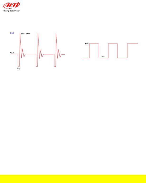
2.4.4 – Sampling the RPM from the coil: low voltage RPM input
To sample the RPM signal from the coil on a low voltage input (from 150 to 400 V), connect:
•cable labelled “RPM” (MXL Strada/Pista) to the ECU RPM output that manages the coil;
•cable labelled “RPM 150-450V” (MXL Pro05) to the ECU RPM output that manages the coil.
In case the vehicle is not equipped with an ECU take the signal directly from the low tension coil control of the coil.
MXL may not sample correctly the coil signal because this looks unstable. To filter the signal use an “RPM coil-ECU” adapter (optional shown here below). It is a double purpose filter that allows to sample the RPM from the coil and squares the signal wave form.
•connect the blue adaptor cable labelled “RPM form” to the cable labelled
“RPM” of MXL Strada/Pista wiring.
•connect the blue adapter cable, labelled “RPM form” to the blue cable labelled “RPM 8-50V” of MXL Pro05 wiring – pin 12 of 37 pins Deutsch type connector.
•connect the red interface cable labelled “V battery” to the positive pole of the vehicle battery. It is suggested to connect the red cable downstream the vehicle master switch.
•connect the black interface cable – labelled GND – to the chassis earth of the vehicle wiring (see GND paragraph of this user manual for further information).
•connect the adapter cable labelled “RPM-Coil 150-400 V” to the coil control.
www.aim-sportline.com |
11 |
MXL
User manual
Release 1.24
The images below show on the left a non filtered unstable coil signal and on the right a filtered one.
2.5 – How to connect MXL analog channels
MXL is equipped with numerous analog and digital channels and their number changes depending on the model.
MXL Strada/Pista models have 8 analog channels and 3 digital channels:
•RPM
•1 speed channel
•Lap Time.
MXL Pro model has 8 analog channels and 6 digital channels:
•RPM
•4 speed channels
•Lap times.
MXL Pro05 has 12 analog channels and 6 digital channels:
•RPM
•4 speed channels
•Lap time.
To connect the analog channels use the logger wiring. All cables are labelled with the channel number.
Warning: digital channels have to be connected to a sensor and configured.
Refer to each wiring user manual to know which sensor can be connected to each channel.
Please note: not all channels have a +Vb.
•MXL Strada/Pista: +Vb on channels 4, 5, 6, 7 and 8;
•MXL Pro05: +Vb on channels 8, 9, 10 and 11.
Refer to Race Studio Configuration user manual to know how to configure each channel and how to manage possible custom sensors not included in the software database.
www.aim-sportline.com |
12 |
MXL
User manual
Release 1.24
2.6 – How to install and power transmitter and receiver
AIM provides a range of devices for lap time detection. MXL works with infrared transmitter and a receiver only.
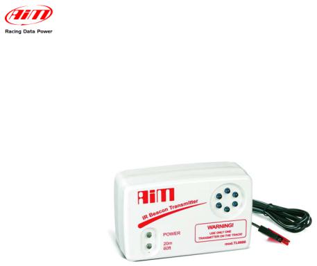
2.6.1 – Infrared transmitters
AIM lap transmitter is show here below.
The transmitter can be internally or externally powered:
•internally: with 8 AA batteries (placed in the transmitter case); when battery charge status is low, Power led starts blinking each second (1 Hz);
•externally: with an external 12V power cable; when battery charge status is low, Power led starts blinking each second.
The transmitter has two working mode:
•Low power mode: for tracks less than 10 m (30 ft) wide;
•High power mode: for tracks more than 10 m (30 ft) wide; in this second case
12V external power is required and both led switches on when the transmitter is switched on.
www.aim-sportline.com |
13 |
 Loading...