


Dear MyChron 3 Owner
The MyChron 3 represents the new generation of AiM data acquisition systems that provides the kart racer with a sophisticated and easy to use display normally reserved for premium sports cars.
Its configurable graphic RPM display, magnetic sensor for kart tracks with magnetic strips installed, the capacity to record up to 250 laps, the ability to measure water temperature (exhaust gas or cylinder head), the high number of splits per lap (up to 5 ) and the auto power off (after 10 minutes of inactivity) make MyChron 3 a great tool for monitoring the kart engine as well as kart and driver performance.
Our Customer Service is available every day from 9 to 5 and at most all the major races throughout the country to provide you with personal service. Please call our toll free number (800.718.9090 in the USA) or visit our website www.aimsports.com or www.aim-sportline.com if you have any questions, need help, or want to give us feedback.
Thank you for your MyChron 3 purchase.
1

Aim HeadQuarter in Cernusco sul Naviglio – Italy
2

Table of contents |
|
GETTING STARTED WITH MYCHRON 3................................................................... |
4 |
MYCHRON 3 AND ITS PARTS ................................................................................... |
6 |
The Display...................................................................................................................... |
7 |
The Keyboard .................................................................................................................. |
8 |
The RPM Cable ............................................................................................................... |
9 |
The Thermocouple ......................................................................................................... |
10 |
The LAP receiver........................................................................................................... |
11 |
The Optical beacon........................................................................................................ |
12 |
HOW TO INSTALL MYCHRON 3............................................................................. |
14 |
Installing and changing the display batteries................................................................ |
14 |
Installing MyChron 3 on the steering wheel.................................................................. |
15 |
Installing the RPM clip.................................................................................................. |
16 |
Installing the water thermocouple ................................................................................. |
17 |
Installing the EGT thermocouple................................................................................... |
18 |
Installing the underspark thermocouple........................................................................ |
20 |
Connecting cables to MyChron 3 .................................................................................. |
21 |
HOW TO USE MYCHRON 3 .................................................................................... |
23 |
Configuration functions................................................................................................. |
23 |
Utility functions ............................................................................................................. |
31 |
Maintenance .................................................................................................................. |
35 |
MYCHRON 3 AND THE COMPUTER ........................................................................ |
36 |
Software installation...................................................................................................... |
37 |
Installing the USB drivers ............................................................................................. |
42 |
CONFIGURATION VIA SOFTWARE .......................................................................... |
44 |
Channels settings........................................................................................................... |
49 |
Configuration via “Visualization” pushbutton.............................................................. |
50 |
Transmitting the configuration to MyChron 3............................................................... |
51 |
QUICK REFERENCE GUIDE..................................................................................... |
53 |
|
3 |

Getting Started with MyChron 3
Here are the parts of your system (see figure 1.1 on the next page):
•MyChron 3 Display Unit ( 1 ).
•RPM sensor ( 2 ).
•Thermocouple – You may choose Water Sensor ( 5 ), Exhaust Gas Sensor ( 9 ) or Underspark Temperature Sensor ( 10 ). The Water Temperature Sensor may be provided with an M5 connection or a 1/8 connection.
•Optional water thermocouple M5 fitting ( 11 ).
•Thermocouple extension cable ( not shown ).
•Lap Timer, which can be optical ( 3 ) or magnetic ( 8 ). The optical one is provided with the optical transmitter ( 4 ), while the second one may work only in the kart tracks provided with a magnetic strip.
•External power wire for Infrared transmitter ( 6 ) for IR version.
•Optional USB data download cable ( 7 )
4

Fig 1.1 Packing list
Also available
5
MyChron 3 and its parts
Before installing MyChron 3, please read these installation instructions carefully. It is very important that your MyChron 3 is correctly installed to capture consistent and accurate data. Incorrect installation may result in system malfunction.
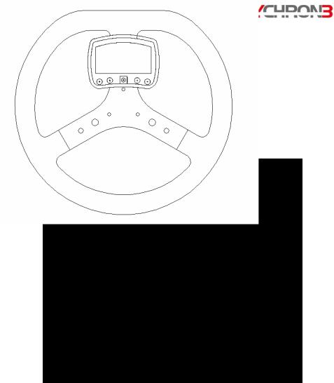
In the following drawing a MyChron 3 is shown mounted on a kart steering wheel.
6
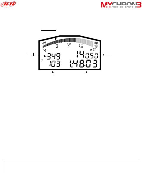
The Display
RPM display
 Low battery warning
 Night Vision
Temperature
RPM digital display
Temperature  measure unit
Lap number |
|
|
|
Lap time |
|
||||
|
|
|
The wide display with backlight generally shows RPM, temperature, completed lap number and, when the kart passes in front of the beacon, it shows the Lap Time ( or Split Time ). It is also possible to configure a second page ( using button VIEW ) in order to see RPM digital value ( as showed in the previous drawing ) or best lap time. When you are not running it is also possible ( using button VIEW ) to see the battery voltage.
The display also shows some small icons, showing the configured Temperature Measure Unit ( Celsius [°C] or Fahrenheit [°F] ), the Night Vision option and the Low Battery Warning, which appears when the batteries are down.
Your MyChron 3 has also an automatic power down feature that turns the power off after 10 minutes of inactivity
7
|
|
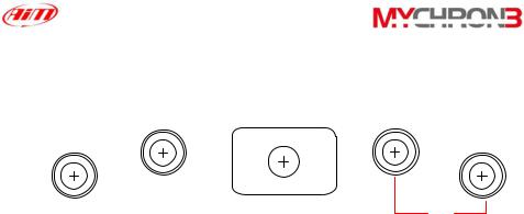
The Keyboard |
|
|
|
|
|
USB |
MEM |
|
|
MENU |
>> |
ok |
VIEW |
||
|
|||||
<< |
|
|
|
on quit |
|
|
|
|
|
off |
The Keyboard, composed by four push-buttons, is used for turning the power ON and OFF, configuring the system, recalling the recorded data and clearing the internal memory.
The four pushbuttons are used for:
MENU/<< Used in configuration to switch to previous option and to turn on backlight during a test
>>Used in configuration to switch to next option.
MEM Used to CONFIRM a configuration and to retrieve recorded data. VIEW Used to TURN ON the instrument, to exit configuration menu, or to switch the display from “digital RPM” value to “battery voltage”
or to “best lap time”
To switch the gauge OFF press MEM and VIEW at the same time
To run the system in DEMO MODE, press the VIEW button while holding down the MENU/<< and >> buttons.
8
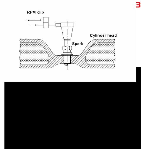
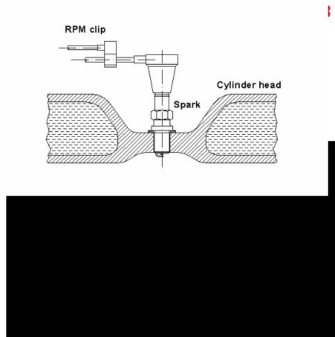
The RPM Cable
This clip wire is designed to be plugged directly on the spark plug wire and it is used for RPM pick up from single cylinder 2-4 stroke engines.
When running the RPM cable along the chassis between the MyChron 3 display unit and spark plug wire, the RPM cable should be positioned as far as possible from the thermocouple wire.
9
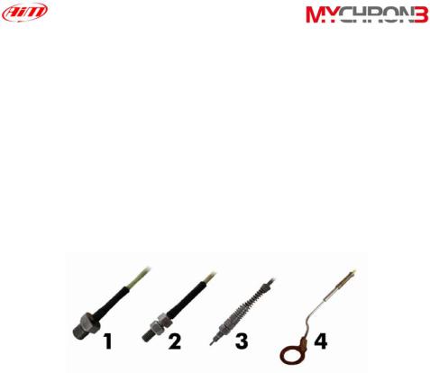
The Thermocouple
The MyChron 3 Basic model supports one temperature sensor. There are 4 types of thermocouples ( temperature sensors ) that are available for selection or subsequent purchase:
1.H2O - Water thermocouple1/8 inches type.
2.H2O - Water thermocouple M5 type
3.EGT - Exhaust gas thermocouple
4.CHT - Cylinder head thermocouple
All AiM thermocouple are K-type sensors.
Thermocouple from 2 to 4 are provided with an extension cable (length: 45 inches/1.5m) Thermocouple 1 doesn’t need extension wires (length: 45 inches/1.5m).
10
The LAP receiver
The lap receiver may be infrared or magnetic and is used to recognise a lap marker. The Optic receiver requires an Infrared Transmitter (beacon), at the side of the track; for magnetic receiver, the track must have a magnetic strip installed.
The Infra Red receiver has to “see” the transmitter placed on the trackside; the grey point is the receiver eye.
The Magnetic receiver has to be installed on the floor of the kart, with two tyre wraps. The arrows on the magnetic receiver need to point to the front and rear of the kart
The MyChron 3 automatically recognises the lap receiver ( optic or magnetic ) and so no beacon type configuration is needed.
11
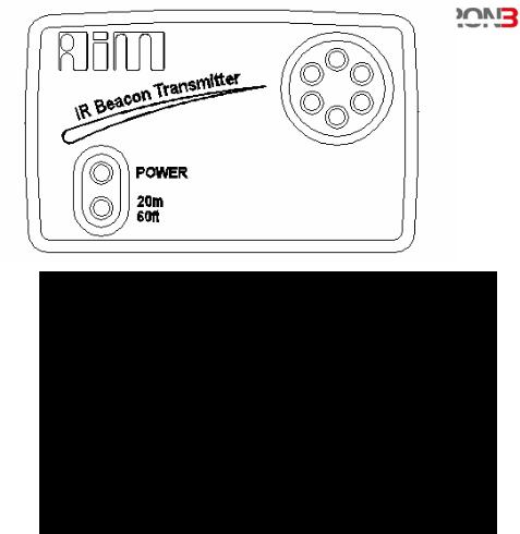
The Optical beacon
The optical Beacon Transmitter has to be placed trackside to mark laps. Ensure that the infrared receiver eye faces the side of the track where the Beacon has been placed, otherwise the system will not record lap time.
The Beacon transmitter is powered using 8 AA batteries or an external 12V power cable. If you are using 8 AA batteries, unscrew the back cover of the Beacon transmitter and place the battery pack into the transmitter casing.
The transmitter has two operating modes: Low power and High power. The Low Power Mode can to be used when the track is less than 30 feet / 10 meters wide, while the High Power mode has to be used when the track is wider than 30 feet / 10 meters.
12
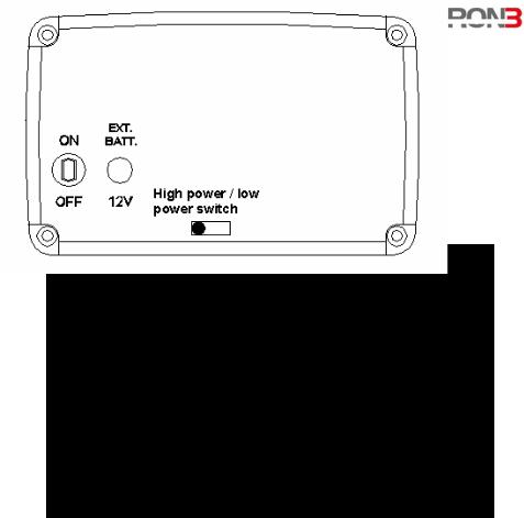
To activate this function, open the Beacon transmitter with a screw driver and move the jumper ( located directly below where the battery pack is attached to the beacon transmitter board ) over either one of the two connectors ( for low power mode ) or over the two connectors ( for high power mode ).
When the Beacon transmitter operates on high power mode, both the power led lights will light up when the transmitter is turned on.
Please, take note that, in High Power Mode, the transmitter has to be powered by an external 12 Volts battery.
13

How to install MyChron 3
Now you can start installing MyChron 3 on your kart. It is recommended to follow these instructions in order to preserve your instrument and to capture consistent and accurate data.
Installing and changing the display batteries
Two AAA alkaline batteries power MyChron 3. The batteries provide approximately 40 hours of use. When the batteries require replacement ( < 2 Volt ), a battery indicator will appear in the top right hand corner of the display.
If battery voltage is very low ( < 1.7 Volt ) it will also appear the text:
LOW BATTERY
If battery voltage is really too low, the system will automatically shut down. Replace both batteries when the battery indicator appears to avoid the system’s shutting down during a test.
To change batteries, remove the two screws on the back of the display unit. To remove the battery pack, hold each corner of the circuit board and pull the board away from the display unit. When inserting the battery pack, ensure that the batteries face the center bolt and the circuit board faces the side of the unit. The white connector should be positioned in the top right hand corner of the display unit, if looking at the display unit from behind.
Do not over-tighten the screws when mounting the battery cover to the back of the display unit.
14
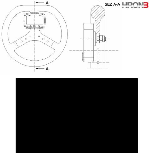
Installing MyChron 3 on the steering wheel
Most of steering wheels have existing holes in the three central arms that will accommodate the MyChron 3 display unit. If the steering wheel arms are solid, mark the point where the hole is to be drilled and then indent a drill reference point with a large nail or hole punch, to minimize drill wander. It is recommended that an 8 to 10 mm drill bit be used. Do not over-tighten the 8 mm nut. Overtightening the nut may cause damage to the display unit casing.
As showed in the previous drawing, we suggest using the plastic washers furnished as equipment to keep your MyChron 3 separate from the steering wheel, in order to avoid possible damage to the display unit.
15
Installing the RPM clip
The RPM sensor clips directly on the spark plug wire. While running the RPM cable along the chassis between the MyChron 3 display unit and the spark plug wire, the RPM cable should be positioned as far as possible from the thermocouple wire, to prevent interference.
It is suggested to use cable ties to securely attach the RPM cable along the chassis to prevent damage.
16
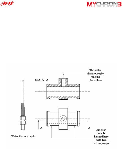
Installing the water thermocouple
The H2O thermocouple can be installed directly into the cylinder head ( if the engine accommodates the thermocouple ) or by using the water thermocouple M5 fitting ( sold separately ) for the M5 type.
The drawing below shows how to correctly install the water thermocouple for the M5 type.
17
 Loading...