

Page 1
RPM Bridge
USER MANUAL
Page 2

RPM Bridge
User manual
Release 1.03
INTRODUCTION
RPM Bridge belongs to the last generation of AIM systems for car installations.
ECU Bridge samples but does not record RPM values coming from the vehicle. Data can be
visualized connecting RPM Bridge to SmartyCam, the on-board camera or to an AIM dash
(MyChron3 Dash, TG Dash, Formula Steering Wheel).
Technical features:
• AIM proprietary CAN protocol for external expansion modules;
• USB communication protocol for programming;
• RPM signal 150-450V coil;
• RPM signal 4-50V square wave;
• external power.
www.aim-sportline.com
1
Page 3

RPM Bridge
User manual
Release 1.03
INDEX
Chapter 1 – Kit and part numbers ........................................................................................ 3
Chapter 2 – RPM Bridge characteristics.............................................................................. 4
Chapter 3 – Installation and powering ................................................................................. 5
3.1 – How to receive the RPM signal ............................................................................................................. 5
3.1.1 – Receiving the RPM signal from the ECU through a square wave signal ....................................... 5
3.1.2 – Sampling the RPM signal from the coil: low voltage RPM input .................................................... 6
Chapter 4 – Connecting RPM Bridge to AIM systems ........................................................ 8
Chapter 5 – Configuring RPM Bridge .................................................................................. 9
5.1 – How to transmit the configuration ..................................................................................................... 10
5.1.1 – Possible problems while transmitting the configuration ............................................................... 10
5.2 – Online .................................................................................................................................................... 10
Appendix – Technical drawing ........................................................................................... 11
www.aim-sportline.com
2
Page 4
RPM Bridge
User manual
0
Chapter 1 – Kit and part numbers
Release 1.03
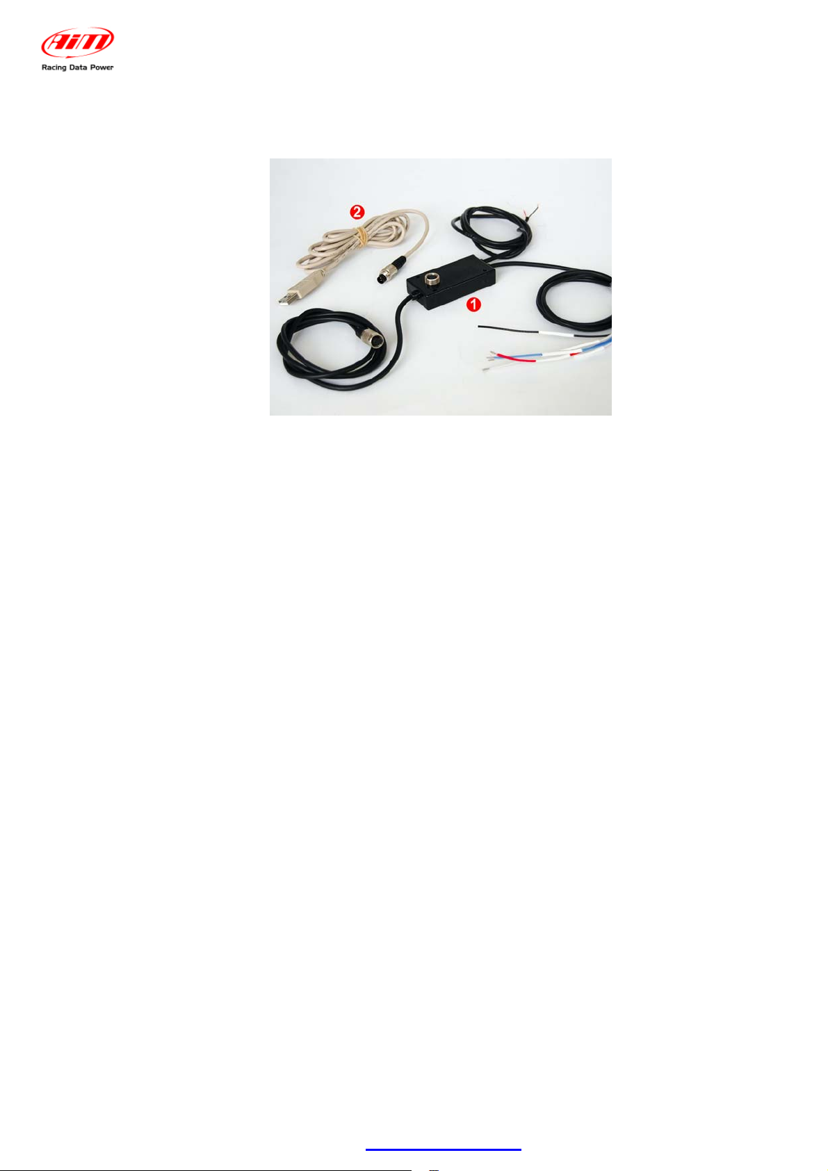
RPM bridge kit includes:
• RPM Bridge (4-50V and 150-450V)(1)
• USB programming cable (2)
RPM Bridge part number is: X90BGRPMBM
www.aim-sportline.com
3
Page 5

RPM Bridge
User manual
1
Chapter 2 – RPM Bridge characteristics
Release 1.03
As shown here below RPM Bridge features a central 3 pins female Binder connector for PC
interface via USB and three lateral cables for CAN communication, power supply and RPM
signal.
www.aim-sportline.com
4
Page 6

RPM Bridge
User manual
2
Chapter 3 – Installation and powering
Release 1.03
Please ensure that RPM Bridge and its expansions are not in contact with heat or
electromagnetic interference sources (like spark plugs and coil).
6
3.1 – How to receive the RPM signal
RPM Bridge can receive the RPM signal in two ways:
• from the ECU through a square wave signal (from 4 to 50V);
• from the coil low voltage input (from 150 to 450V).
9
3.1.1 – Receiving the RPM signal from the ECU through a square wave signal
In case the vehicle ECU does not communicate through the CAN bus, K line or RS232
protocol, it is possible to sample RPM signal using a square wave signal.
With reference to the above image, to receive the RPM from the ECU using a square wave,
connect:
• the cable labelled “RPM 8-50 V” to the RPM signal out coming from the ECU
(or take RPM signal directly on the stock dashboard connector1);
• the red cable labelled “V battery” to the positive pole of the vehicle battery;
• the black cable labelled “GND” to the vehicle chassis earth;
• the CAN connector to SmartyCam or to an AIM dash.
Please note: it is always suggested to connect RPM Bridge to the vehicle master switch.
Always refer to the ECU user manual for further information. In case ECU output signal is not
a steady square wave, an RPM adaptor (optional) is needed.
The images here below show a not-square RPM signal on the left and a filtered one on the
right.
1
RPM signal is often used to power stock dashes. This is why the signal is available on that wiring.
www.aim-sportline.com
5
Page 7

RPM Bridge
User manual
10
3.1.2 – Sampling the RPM signal from the coil: low voltage RPM input
Release 1.03
If the vehicle is not equipped with an ECU, RPM signal can be taken directly from the low
tension control of the coil.
To sample RPM signal from the coil on the dedicated RPM input (from 150 to 450 V)
connect:
• RPM Bridge cable labelled “RPM 150-450 V” to the coil control;
• the red cable labelled “V battery” to the positive pole of the vehicle battery;
• the black cable labelled “GND” to the chassis earth of the vehicle wiring;
• CAN connector to SmartyCam or to an AIM dash;
Please note: it is always suggested to connect RPM Bridge to the vehicle master switch.
The image here below shows a non filtered unstable coil signal.
The coil to sample the signal from, shown here below, is a black cylinder with three cables
(labelled 1,2 and 3).
• Cable labelled 1 is the coil low tension input.
• Cable labelled 2 is connected to the coil.
• Cable labelled 3 is connected to the battery positive pole (+12V).
Moreover the coil is generally grounded with the chassis as shown here below on the right.
www.aim-sportline.com
6
Page 8

RPM Bridge
User manual
Release 1.03
The scheme below shows the voltage in the point labelled “1” in the previous images.
It is reminded that RPM Bridge white cable, labelled “RPM 150-450 V” is to be
connected to the RPM trigger wiring indicated by digit 1 in the previous schemes.
www.aim-sportline.com
7
Page 9

RPM Bridge
User manual
3
Chapter 4 – Connecting RPM Bridge to AIM systems
Release 1.03
RPM Bridge can be connected directly to SmartyCam (top image) or to AIM dashes (bottom
image) through a DataHub.
Warning: connect RPM Bridge to AIM devices when both devices are OFF.
www.aim-sportline.com
8
Page 10

4
Chapter 5 – Configuring RPM Bridge
To configure RPM Bridge:
• run Race Studio 2 software,
• go through these steps: press “AIM System Manager” >> ”SMC Bridge” >> “Go
to”;
• press “New” to create a new configuration;
• “New configuration” panel, shown here below, appears.
RPM Bridge
User manual
Release 1.03
• select RPM Bridge in the drop down menu, fill in the panel and press OK.
The system comes back to “System manager” window. Enable “System Configuration” layer.
www.aim-sportline.com
9
Page 11

RPM Bridge
User manual
Release 1.03
In case an AIM Display is available it needs configuration: activate “Display” layer and select
the right display. Refer to Race Studio Configuration user manual to know how to configure
each display.
7
5.1 – How to transmit the configuration
To transmit the configuration the logger has to be switched on and connected to the PC USB
port through the proper cable. Press “Transmit” button in “System manager” window and the
system will automatically transmit the configuration to the device.
11
5.1.1 – Possible problems while transmitting the configuration
While transmitting the configuration this error message can appear:
Check that the USB cable is correctly plugged in
the PC and in the device USB port, that the logger
is switched on and try again transmitting the
configuration.
8
5.2 – Online
When the configuration has been transmitted to the logger, it is suggested to enter “Online”
pressing the corresponding button on the menu bar, on the left vertical keyboard to verify that
all works properly. Ensure that RPM Bridge is switched on and well connected to the PC.
www.aim-sportline.com
10
Page 12

RPM Bridge
User manual
Release 1.03
5
Appendix – Technical drawing
N.rev. / Rev. N.
Descrizione / Descriptio n
White cable
Data / date
GND
Blue cable
Black cable
RPM 150-450V
RPM 8-50V
GND
Red cable
Black cable
Vb out Max 0,1A
RPM Bridge
+Vb ext
Red cable
4
5
3
1
2
5 pins Binder 712
Solder termination view
female connector pinout
Firma / Sign
CAN+
1
5 pins Binder 712
female connector pinout
GND
2
+Vb
CAN-
345
Contr. da / Ckd. by
+Vbatt
RPM Bridge pinout
Materiale / MaterialQ.tà / Q.tyRif. / Ref.
Progettato da / Designed by Contr. da / Ckd. by
Racing Data Power
5 pins
Binder 712
female connector
Approvato da / Approved by
Titolo / Title
N. disegno / Drawing N.
Nome file / File name
Pinout RPM Bridge
N. articolo / Item N.
Data / Date
Scala / Scale
Foglio / SheetRev. / Rev.
1 of 1
www.aim-sportline.com
11
 Loading...