

Page 1
MyChron Expansion
User Manual
Page 2

MyChron Expansion
User Manual
Release 1.02
This user manual is copyright of Aim srl. All procedures here described can change even
substantially. Please always refer to www.aim-sportline.com
to know the latest procedures.
Aim reserves the right of periodically updating and re-publishing the documentation with no
obligation to notify anybody of such changes.
Aim srl cannot be held responsible for any fault contained in this user manual or for
damages caused by the supply, working or usage of all its parts (hardware, software and
documentation).
www.aim-sportline.com
1
Page 3

MyChron Expansion
User Manual
Release 1.02
INDEX
Chapter 1 – MyChron Expansion and part number ........................................................ 4
Chapter 2 – How to install and connect MyChron Expansion ....................................... 5
2.1 – How to install MyChron Expansion on the kart .................................................................................... 5
2.2 – How to connect MyChron Expansion to MyChron4 ............................................................................. 5
Chapter 3 – How to configure MyChron Expansion........................................................ 6
3.1 – Sensors Setup (Menu<Control panel<Sensors Setup) ..................................................................... 7
3.2 – Speed Setup (Menu<Control panel<Speed Setup) .......................................................................... 8
3.3 – Potentiometers calibration (Menu<Control panel<Sensors Setup<View Sensors) ......................... 8
3.3.1 – Calibrating the steering potentiometer .......................................................................................... 9
3.3.2 – Calibrating throttle and brake potentiometer................................................................................. 9
3.4 – Setting 0-100 generic sensors (expert users only) ............................................................................ 10
3.4.1 – Analog channels connectors pinout ............................................................................................ 10
3.5 – Where to connect MyChron Expansion additional sensors ............................................................... 10
Chapter 4 – How to install and configure speed sensors ............................................ 11
4.1 – Installing the front wheel speed sensor .............................................................................................. 11
4.2 – Installing the rear axle speed sensor ................................................................................................. 11
Chapter 5 – View data on track ....................................................................................... 12
Chapter 6 – Data recall and analysis .............................................................................. 13
Appendix – Technical drawing ....................................................................................... 15
www.aim-sportline.com
2
Page 4

MyChron Expansion
User Manual
Release 1.02
MyChron4 Expansion is the new external expansion module that increases MyChron4
already big potential allowing the connection with other AIM products like LCU-Lambda
Controller, GPS and SmartyCam, the on-board camera.
With MyChron Expansion it is possible to add 4 analog channels – or three analog
channels and a digital one – to MyChron4. MyChron Expansion can support temperature
sensors (only PT100 thermo resistors), potentiometers and displacement sensors – not
contact too.
This new expansion is to be considered as an alternative to MyChron4 eBox
Gold/Extreme.
This manual is to be used as an integration of MyChron4 user manual. Refer to that
document for any further information.
www.aim-sportline.com
3
Page 5
MyChron Expansion
User Manual
0
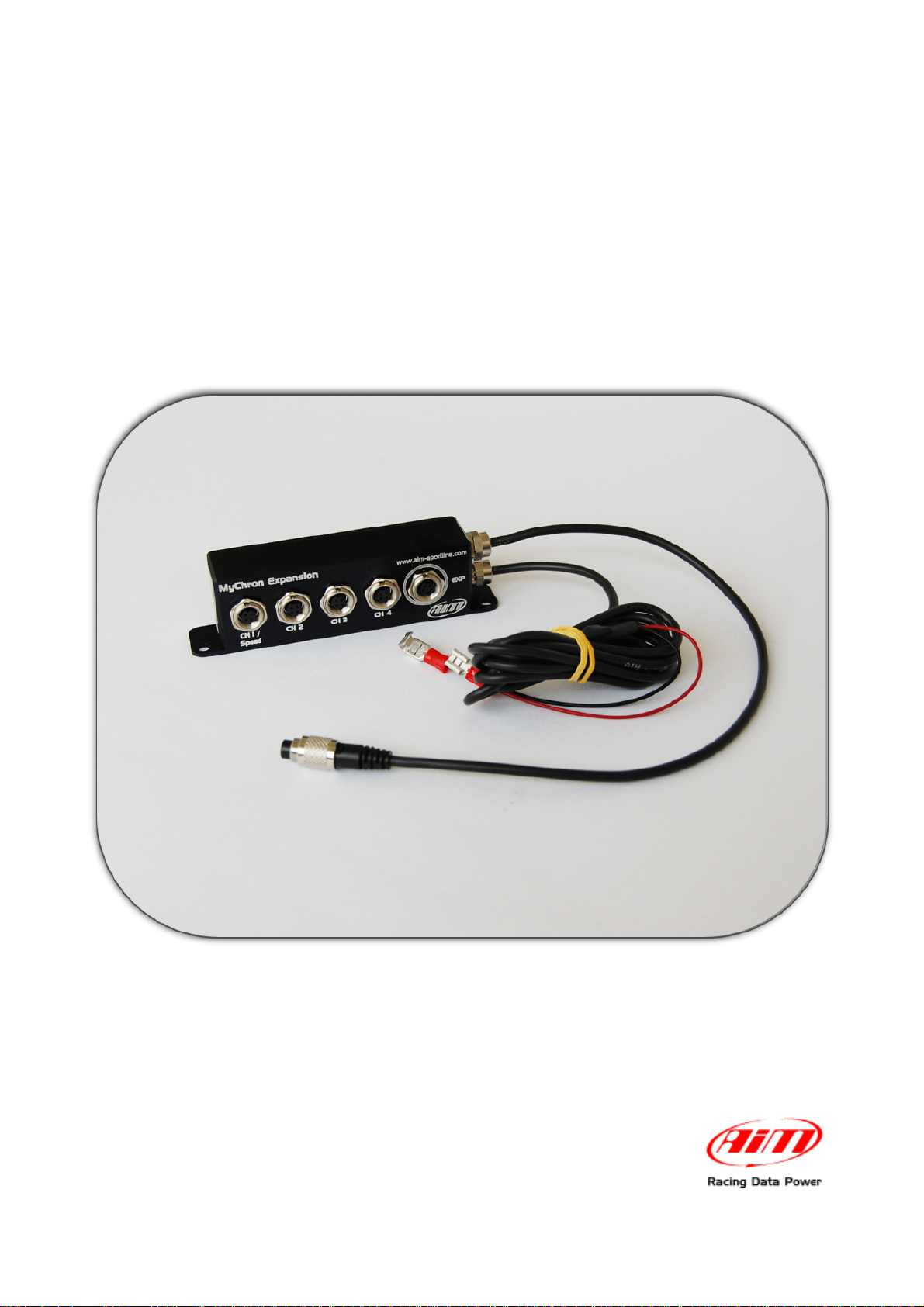
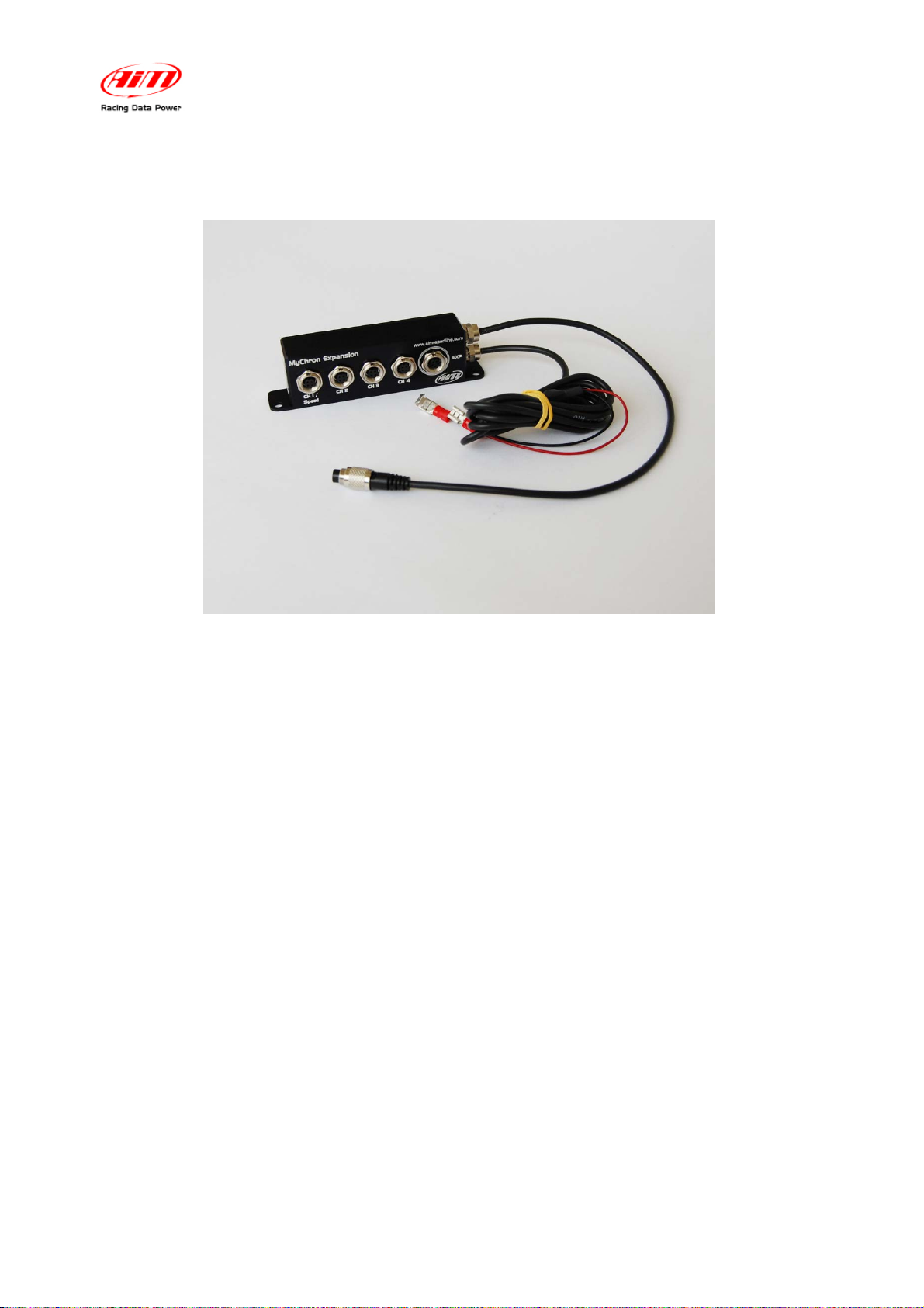
Chapter 1 – MyChron Expansion and part number
Release 1.02
MyChron Expansion is shown here above;
Part number is:
kit MyChron Expansion: X08MYEXUCS;
www.aim-sportline.com
4
Page 6

MyChron Expansion
User Manual
1
Chapter 2 – How to install and connect MyChron Expansion
Release 1.02
MyChron Expansion allows MyChron4 to sample temperatures, displacements and –
configuring channel 1 as digital – a speed. A correct installation of this expansion and its
sensors is thereby mandatory to sample correct and consistent data.
7
2.1 – How to install MyChron Expansion on the kart
Below images show how to install MyChron Expansion.
8
2.2 – How to connect MyChron Expansion to MyChron4
Once correctly installed, MyChron Expansion is to be connected to MyChron4 to be
configured. The connection comes plugging MyChron Expansion cable in MyChron4
connector labelled Exp/PC as shown here below.
Warning: connect MyChron Expansion to MyChron4 OFF.
www.aim-sportline.com
5
Page 7

MyChron Expansion
User Manual
2
Chapter 3 – How to configure MyChron Expansion
Release 1.02
MyChron Expansion is to be configured using MyChron4. Press “MENU” and select
“Control Panel” icon highlighted here below.
Once MyChron4 is connected to MyChron Expansion, its “Control Panel” menu shows
additional options. In particular – if channel 1 is configured as speed – its configuration
icon appears as shown here below.
www.aim-sportline.com
6
Page 8

MyChron Expansion
User Manual
13
3.1 – Sensors Setup (Menu<Control panel<Sensors Setup)
Release 1.02
This additional function appears only when MyChron4 is connected to MyChron
Expansion or to eBox. Here below is the menu.
All channels default setting is “None” and each type of sensor can be set on one channel
only.
Channel 1 can be configured as analog or digital: it can support a speed sensor and
shows the speed value on the display. “Speed” is thereby included in this channel
available options as shown here above.
Channels from 2 to 4 can support different sensors and the different labels are written
bold in the following list.
• Brake pressure sensor (PresBrk);
• Magnetic position sensor: shows exhaust gas valve opening in mm (GasValve);
• Magnetic position sensor: shows the throttle opening percentage, needs calibration
and its working range is 0-100% (MagThrot);
• Magnetic position sensor: shows brake pedal percentage of travel and its working
range is 0-100% (MagBrk);
• Temperature Sensor: shows kart cooling water temperature (WaterTemp)
• Temperature Sensor: shows Cylinder Head Temperature (CHT)
• Throttle Potentiometer: shows throttle pedal percentage of travel and needs
calibration (Throt);
• Brake Potentiometer: shows brake pedal percentage of travel and needs calibration
(PotBrk);
• Steering Potentiometer: is a mid zero potentiometer, shows the steering movement
in a range -100/+100 and needs calibration (Steer)
• Generic sensor for custom measurement: is a zero based potentiometer and shows
sampled values in a 0-100 range (0-100).
Once all connected sensors are set it is necessary to set pressure measure unit and to
calibrate sensors that need it.
Selecting “View sensors” the display shows sensors instant values and allows the
calibration needed.
7
www.aim-sportline.com
Page 9

MyChron Expansion
User Manual
Release 1.02
This screen is only available with the kart engine off; it is thereby necessary to manually
move the pedals to change shown values.
In case one or more sensors that need calibration are set, the system shows “CAL” button.
Otherwise it does not.
9
3.2 – Speed Setup (Menu<Control panel<Speed Setup)
It is an additional function that appears in the menu only when MyChron4 is connected to
MyChron Expansion and channel 1 is set on “Speed”. Selecting this icon the related
configuration screen appears.
Please note: modifying speed measure unit from km/h in mph wheel circumference
is recomputed in inches too.
10
3.3 – Potentiometers calibration (Menu<Control panel<Sensors
Setup<View Sensors)
Magnetic position sensor (“MagAccel”), throttle (“Throt”), brake (“PotBrk”) and steering
(“Steer”) potentiometer need calibration: press “CAL” button highlighted in “View Sensors”
screen here below (paragraph 4.1).
www.aim-sportline.com
8
Page 10
MyChron Expansion
17
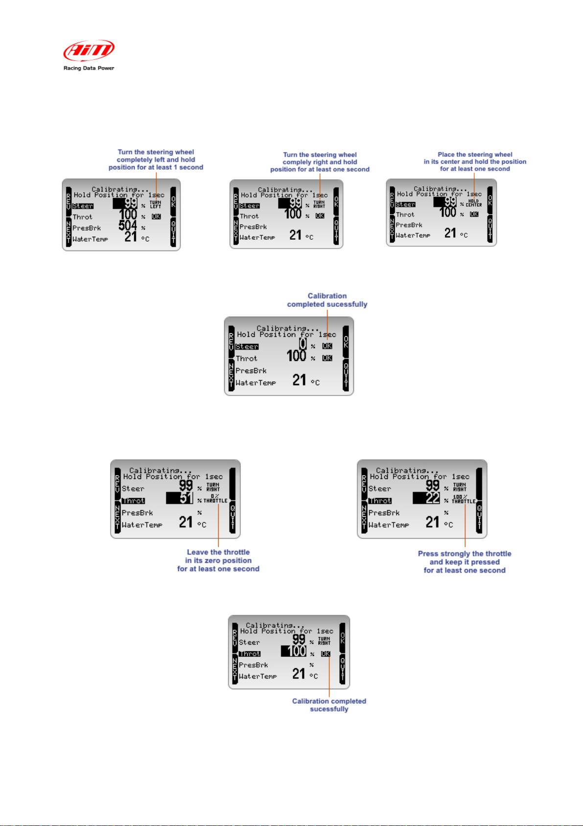
3.3.1 – Calibrating the steering potentiometer
The system calibrates the sensors in vertical order. Use “Prox” to scroll.
The display shows three screens sequentially: follow its instructions.
When calibration is over the system confirms. To invert set values press “REV”.
User Manual
Release 1.02
16
3.3.2 – Calibrating throttle and brake potentiometer
The display shows two screens sequentially: follow its instructions.
When calibration is over the system shows confirmation.
When all potentiometers calibration is over press “OK” and the system saves calibration
showing confirmation message.
9
www.aim-sportline.com
Page 11

MyChron Expansion
User Manual
14
3.4 – Setting 0-100 generic sensors (expert users only)
Release 1.02
This function manages custom sensors. Values are linked following this calibration curve:
• 0 counts – 0 Volt
• 100 counts – 5 Volt
Calibration curve is already set and needs no calibration.
Always refer to the sensors user manuals and datasheets supplied by the sensor
manufacturers for any further information.
18
3.4.1 – Analog channels connectors pinout
5 pins female Binder connector of CH1, CH2, CH3 and CH4 analog channels is shown
here below.
15
3.5 – Where to connect MyChron Expansion additional sensors
Additional sensors are connected to MyChron Expansion screwing them in their own
connectors. Below image shows connectors position and function.
www.aim-sportline.com
10
Page 12

MyChron Expansion
User Manual
3
Chapter 4 – How to install and configure speed sensors
Release 1.02
There are two types of available speed sensors: front wheel speed sensor and rear axle
speed sensor. Here below the installation instructions.
11
4.1 – Installing the front wheel speed sensor
Front wheel speed sensor (above on the left) has to be oriented as shown above on the
right, at 5 mm distance from the magnet.
12
4.2 – Installing the rear axle speed sensor
Rear axle speed sensor shown here above on the left fits an installation on the bearing
housing of the axle and can also be provided with a magnetic ring. It is to be installed at 35 mm from the magnet (or magnetic ring).
www.aim-sportline.com
11
Page 13

MyChron Expansion
User Manual
4
Chapter 5 – View data on track
Release 1.02
During the track session it is possible to see different values on the display according also
to the sensors installed on the kart. On track MyChron4 display shows this screen.
Pressing “ON/VIEW” it is possible to view speed – if configured – in spite of RPM digital
value (below image).
If power valve sensor is installed and the related channel configured, when power valve
opens MyChron4 display shows an icon as here below.
www.aim-sportline.com
12
Page 14

MyChron Expansion
User Manual
5
Chapter 6 – Data recall and analysis
Release 1.02
When a track session is over data stored in MyChron4 can be recalled pressing
“MEM/OK”.
The first page shown is session summary.
With “>>/OFF” and ”MENU/<<” all sessions are scrolled.
Pressing again “MEM/OK”, the second page – Lap time histograms – appears; it is just
the same shown by MyChron4. Refer to that logger user manual for any further
information.
Selecting a lap from histogram page and pressing again “MEM/OK” the third page – RPM
graph – shown here below appears.
“>>/OFF” and ”MENU/<<” scrolls temperature and RPM punctual values. “ON/VIEW”
shows other temperatures in the same page.
www.aim-sportline.com
13
Page 15

MyChron Expansion
Pressing again “MEM/OK” the fourth page – power valve graph – appears.
Pressing again “MEM/OK” the fifth page – lap summary – appears.
User Manual
Release 1.02
Use “>>/OFF” and ”MENU/<<” to scroll laps and “ON/VIEW” to see temperature values.
www.aim-sportline.com
14
Page 16

MyChron Expansion
User Manual
Release 1.02
6
Appendix – Technical drawing
N. rev. / Rev. N.
Descrizione / Description
CAN BUS
www.aim-sportline.com
EXP
POWER SUPPLY
Firma / Signature Contr. da / Ckd. by
4CAN-
2GND
3+VB
5+Vbext
1CAN+
4
5
3
1
2
5 pins male
Binder connector pinout
+Vb
GND
CAN-
CAN+
+Vbext
black cable
GND
red cable
+VBext
Data / Date
Exp.
1
4
2
3
5
+Vb
GND
+Vref
Analog Input 4
1
4
2
2
1
3
5
4
connector pinout
5 pins Binder female
3
+Vb
GND
+Vref
Analog Input 3
1
4
2
3
Channel Expansion Pinout
CH 2 CH 3 CH 4
CH 1/
Speed
MyChron Expansion
Rif. / Ref.
Progettato da / Designed by Contr. da / Ckd. by Approvato da / Approved by Nome file / File name Data / Date Scala / Scale
Q.tà/Q.ty
L.I.
Material / Material N. articolo / Item N.
Racing Data Power
Titolo / Title
N. disegno / Drawing N. Rev. / Rev. Foglio / Sheet
2
1
4
3
connector pinout
4 pins Binder female
Pinout MyChron Expansion
Analog Input 2
Channel 2 Channel 3 Channel 4
1
Analog Input 1
1
Channel 1/ Speed
+Vb
GND
2
3
+Vb
GND
234
+Vref
4
+Vref
1 of 1
15
www.aim-sportline.com
 Loading...