

Page 1
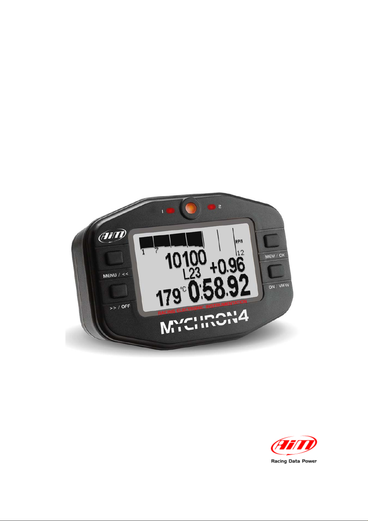
MyChron4
User Manual
Page 2

MyChron4 is an extremely innovative instrument in the world of multi-purpose kart
loggers. Designed and developed to be the heart of a modular end expandable
system, MyChron4 perfectly connects to a wide range of expansions.
This characteristic makes it unique and fitting any pilot need: from the beginner that
needs few basic information to the pro that needs to analyse his and its kart
performances in detail.
Moreover, thanks to the numerous and innovative functionalities of Race Studio
Analysis, the analysis software, strengths and weaknesses of any test session will
be analyzed in an easy and intuitive way. The software is available for free download
at www.aim-sportline.com and www.mychron4.com.
Equipped with a wide graphical display, MyChron4 can display sampled data as
histogram and, using MyChron4 Picture Manager, the free software, it is possible to
upload bitmap images, like, for example your team logo.
When connected to the expansions that AIM designed and developed for his most
innovative loggers, from Gps Module, to Data Hub, from Lambda controller to
eBox, MyChron4 becomes a data logger with a virtually infinite number of channels.
Moreover, thanks to the practical download via Data key, MyChron4 does not need
a Computer immediately available on the track and allows data download on different
computers.
MyChron4, like all AIM products, is always improving: this is why it is suggested to
periodically check www.aim-sportline.com or www.mychron4.com to know if AIM
released new firmware and/or software for MyChron4.
Page 3

MyChron4
User Manual
Release 1.03
INDEX
1 – MyChron4 display............................................................................................... 4
2 – MyChron4 connections and power................................................................... 5
2.1 – MyChron4 external power cable.............................................................................................6
3 –Temperature sensors for MyChron4.................................................................. 7
4 – MyChron4 receivers ........................................................................................... 8
5 – MyChron4 installation........................................................................................ 9
5.1 – Fixing RPM cable on 4 strokes engines (Honda, Briggs & Stratton).................................. 9
5.2 – Fixing RPM cable on 2 strokes engines (Tag, Junior, ICA, FA, ICC ecc..)....................... 10
6 – MyChron4 configuration and wizard............................................................... 11
6.1 – MyChron4 configuration menu............................................................................................. 12
6.2 – Control panel or custom configuration ............................................................................... 13
6.2.1 – RPM Setup .......................................................................................................................15
7 – MyChron4 data analysis................................................................................... 16
7.1 – Session Summary..................................................................................................................16
7.2 – Lap time histogram................................................................................................................17
7.3 – RPM Graph.............................................................................................................................. 18
7.4 – Split summary ........................................................................................................................ 19
7.5 – Best Rolling Lap and Best theoretical................................................................................. 20
8 – Data key for data download............................................................................. 21
8.1 – MyChron4 data download ..................................................................................................... 21
9 – MyChron4 firmware upgrading (firmup)......................................................... 23
www.aim-sportline.com – www.mychron4.com
3
Page 4
MyChron4
User Manual
Release 1.03
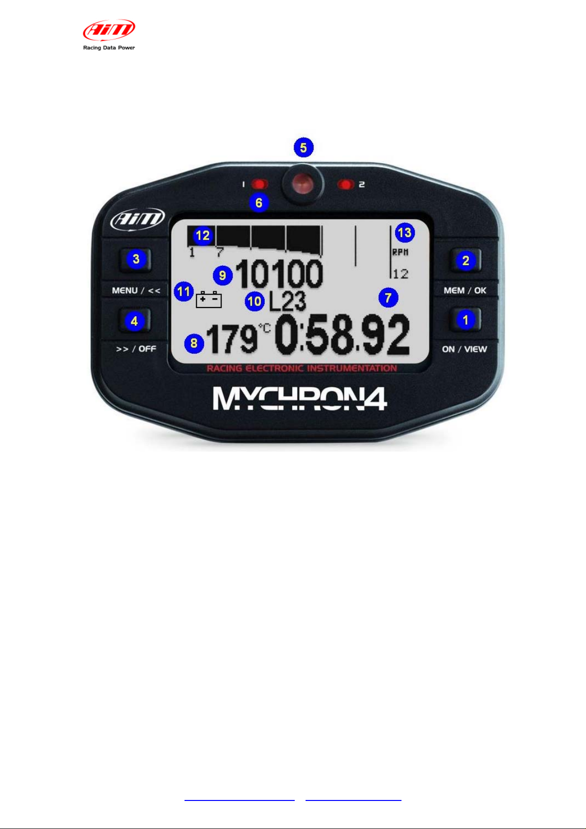
1 – MyChron4 display
MyChron4 display shows a lot of information. Here below they are explained in detail.
1. Power on button
2. Data recall button
3. Menu and scroll button
4. Power off and scroll button
5. RPM alarm led
6. Led AL1 temperature alarm
7. Lap time
8. Temperature value with configurable unit of measure
9. Digital RPM value
10. Lap number
11. External battery alarm
12. RPM graph bar
13. Bar graph scaling in thousands
www.aim-sportline.com – www.mychron4.com
4
Page 5
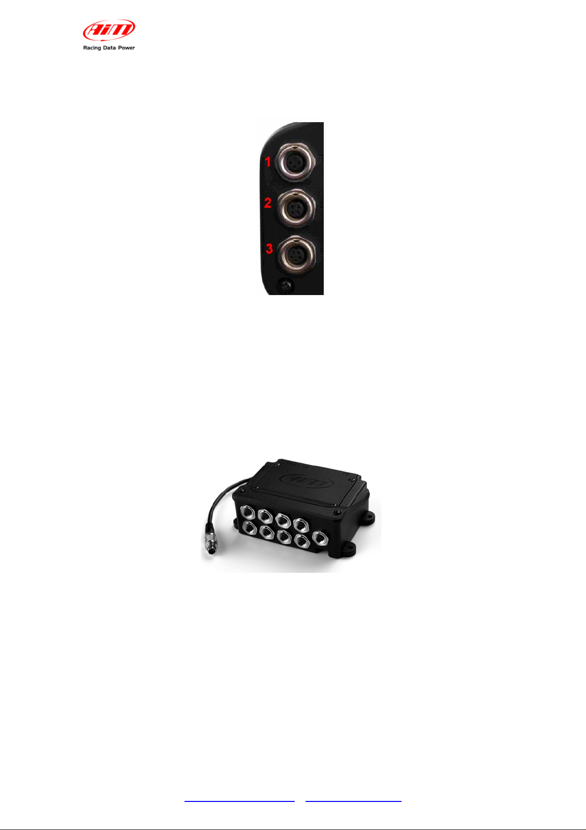
2 – MyChron4 connections and power
On the back of MyChron4 are three connectors, shown below.
Connector 1 –Temperature input
MyChron4
User Manual
Release 1.03
It allows the connection of a temperature sensor among those available to measure
water, cylinder head or exhaust gas temperature.
Connector 2 – Lap time receiver
It allows to connect optical or magnetic lap time receiver.
Connector 3 – eBox input
It is for MyChron4 external power, eBox and Data key connection, data download
on a Pc. Here below MyChron4 eBox is shown.
www.aim-sportline.com – www.mychron4.com
5
Page 6

MyChron4
User Manual
Release 1.03
2.1 – MyChron4 external power cable
MyChron4 can also be powered from an external power source but in this case it
needs the proper power cable, shown below.
External power cable has a double function: it powers MyChron4 using the engine
battery or the power produced by the master switch and detects RPM value through
this same cable when it is connected to the master switch, avoiding the installation of
RPM cable. External power cable is expected for some 4 stroke engines (Honda,
Briggs & Stratton).
Note: MyChron4 has an auto-power off function after eights minutes of inactivity that
switches the logger off also if externally powered.
www.aim-sportline.com – www.mychron4.com
6
Page 7

MyChron4
User Manual
Release 1.03
3 –Temperature sensors for MyChron4
MyChron4 can be connected to different temperature sensors, shown below.
CHT Thermo resistor:
detects the temperature of the cylinder
head and should be mounted removing
the spark washer to keep the same
compression ratio.
CHT Thermocouple:
Detects the temperature of the head of
the engine and should be mounted
removing the spark washer to keep the
same compression ratio.
Water Thermocouple:
Should be mounted on the proper
adaptor - shown on the right - wrapping
the thread with Teflon™ to ensure the
seal.
EGT Thermocouple:
Should be installed on the exhaust pipe
at a distance of 100 – 120 mm from the
piston shell to have a correct reading of
the value.
www.aim-sportline.com – www.mychron4.com
7
Page 8
MyChron4
User Manual
Release 1.03
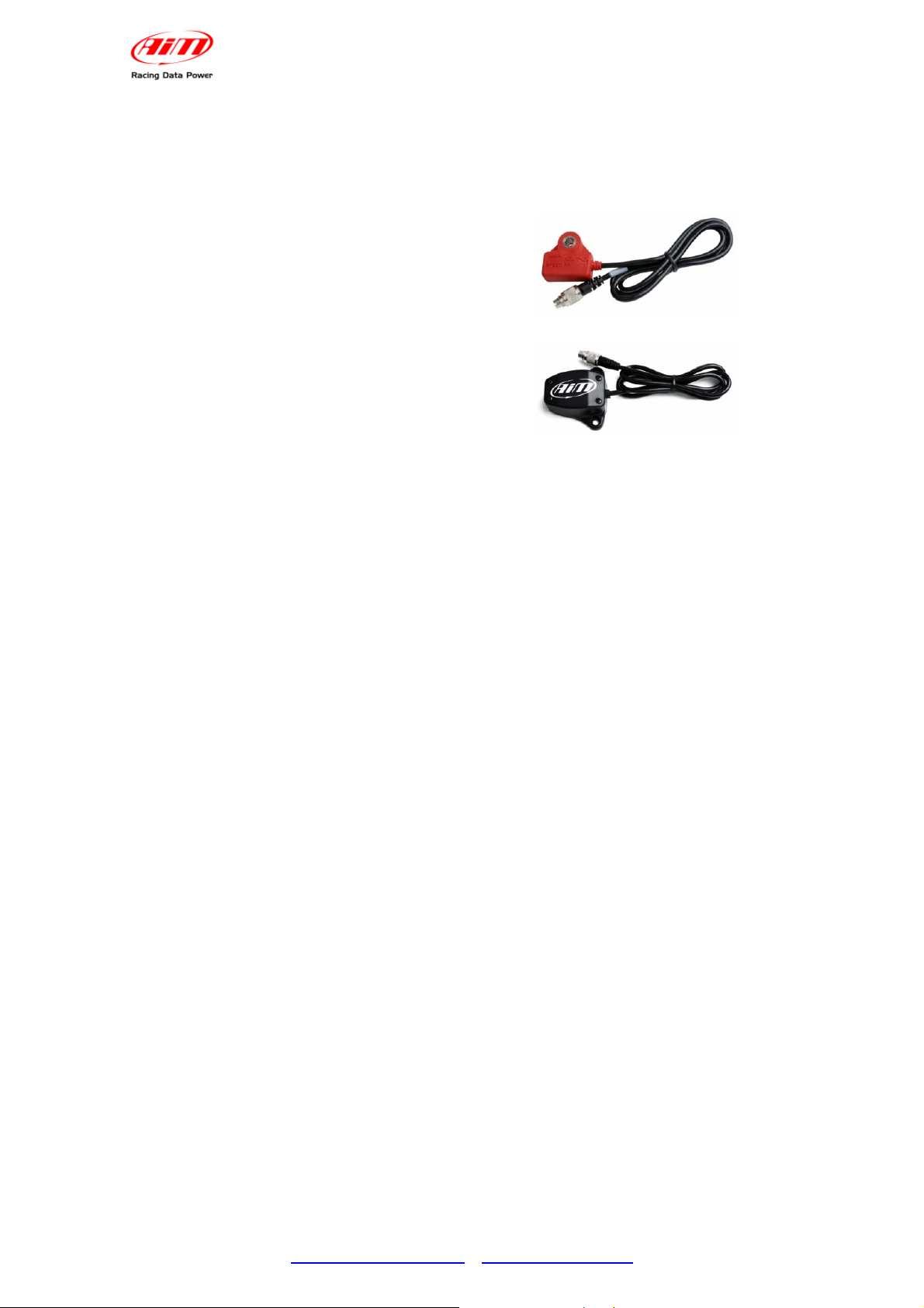
4 – MyChron4 receivers
MyChron4 supports both optical and magnetic lap receiver (shown below). The
system automatically recognizes the connected receiver.
Magnetic receiver
Optical receiver
As explained more in detail in the chapter concerning MyChron4 configuration, in
case the track has more magnetic strips/optical transmitters, it is necessary to set the
logger as to indicate:
• number of magnetic strips /transmitters installed on the track
• magnetic strip/transmitter corresponding to start/finish line
www.aim-sportline.com – www.mychron4.com
8
Page 9

MyChron4
User Manual
Release 1.03
5 – MyChron4 installation
Pay particular attention to this step to allow MyChron4 work properly.
To minimize logger vibrations the rubber washers supplied with the kit should be
mounted over and under the steering spoke as shown below:
Moreover it is suggested to fix RPM cable (in case of internal power) on the spark
plug cable following the specifications of the different engines.
5.1 – Fixing RPM cable on 4 strokes engines (Honda, Briggs &
Stratton)
4 strokes engines have a very weak power-on system. It is thereby necessary to
wrap more times the cable on the spark plug cable, as shown below, to make the
logger become more sensitive.
Wrapping of RPM cable on spark cable Particular of the wrapping
www.aim-sportline.com – www.mychron4.com
9
Page 10

MyChron4
User Manual
Release 1.03
5.2 – Fixing RPM cable on 2 strokes engines (Tag, Junior, ICA, FA,
ICC ecc..)
Power-on of 2 strokes engines supplies a very strong signal; it is thereby sufficient to
fix RPM cable on the spark plug cable using the proper clip as shown below:
Wrapping of RPM cable on spark cable Particular of the wrapping
www.aim-sportline.com – www.mychron4.com
10
Page 11

MyChron4
User Manual
Release 1.03
6 – MyChron4 configuration and wizard
To enter configuration menu press MENU button. The first configuration is made
trough the Wizard, a sort of tutorial menu that allows the user to quickly configure all
needed parameters.
Warning: the Wizard has to be completed at least once or it will re-start at the first
switch on.
Wizard steps are:
• Language
• Pilot name
• Drive Setup (in case of gearbox set the number of gears)
• Temperature unit of measure (Fahrenheit – Celsius)
• RPM max value
• RPM tattle
• M4 Temp 1 Alarm
• Adjust Hour/date
Almost all Wizard steps are extremely intuitive and do not require a particular
explanation, except, may be, “Drive Setup”:
• Direct drive: used in karts without clutch, like classical Formula and ICA;
• Low stall clutch: used in Rotax Max, TAG, JICA, HPV, Comer, and in most
4 strokes engines
• Gearbox: in case this drive type is selected the user is required to insert the
number of gears.
Note 1: the engaged gear number is shown on the display only if MyChron4 is
connected to eBox that, managing speed signal, allows to compute the engaged
gear using the proper algorithm (based on RPM and speed).
Note 2: in case of gearbox and direct drive type “predictive” option won’t be
available.
www.aim-sportline.com – www.mychron4.com
11
Page 12

MyChron4
User Manual
Release 1.03
6.1 – MyChron4 configuration menu
Press MENU button to enter the configuration. In case the Wizard has been
activated and completed at least once, the menu below appears:
Each icon allows the user to enter a configuration function:
Backlight icon: allows the user to enable/disable the display
backlight.
At logger power-on it is disabled and disables at power-off.
Session mode icon: allows the user to set session mode as:
• lap counter: the logger shows the incremental number of
run laps.
• count down: the logger shows the remaining time to the
end of the qualify or the race
Obscuring time icon: allows the user to set minimum lap time and
obscuring time.
It is very useful to avoid false lap times in case more magnetic strips
or transmitters are installed on the track. From start/finish line and
for the set period of time the receiver won’t record signals.
Track icon: allows the user to set the track name.
Track name is associated to each sampled run, downloaded to the
PC and managed by Race Studio 2 software.
It is possible to insert track names and select them when needed.
Configuration icon: allows the user to enter MyChron4 custom
configuration. Refer to the paragraph concerning control panel for
further information.
Configuration Wizard icon: enters MyChron4 configuration wizard
that allows the user to quickly set the basic parameters the logger
needs at start up.
Hour meter Icon: allows the user to manage the logger hour
meters. MyChron4 manages 5 hour meters four of which resettable,
that can be associated, for example to four different engines, and a
fifth one not resettable
Language icon: allows the user to select the logger language.
MyChron4 manages these languages: English, Italian, Dutch,
French, Deutsch, Japanese, Spanish, Swedish and Portuguese.
www.aim-sportline.com – www.mychron4.com
12
Page 13

6.2 – Control panel or custom configuration
Selecting configuration icon a sub-menu appears:
Each icon allows the user to set different functions:
Clear test data: allows to delete data stored in MyChron4 memory.
MyChron4
User Manual
Release 1.03
RPM Setup: enters a sub-menu explained in the related paragraph
Set Temperature: allows the user to link temperature alarm threshold
value to one of MyChron4 lateral led and to set temperature unit of
measure.
Drive setup: as explained in configuration wizard paragraph this function
allows the user to set drive type and in case, kart gears number (accepted
values from 2 to 6).
Lap / split Setup: selecting this icon the related sub-menu appears:
• Total magnetic strips: allows the user to set the number of
magnetic strips /optical transmitters installed on the track.
• Split mode: allows the user to show split as absolute value
(actual) or as difference in respect of best lap (+/- best)
• Start line number: in case of a track with more than one optical
transmitter/magnetic strip it is required to set the one used as
reference for lap time.
www.aim-sportline.com – www.mychron4.com
13
Page 14

MyChron4
User Manual
Release 1.03
System Setup: selecting this icon the related sub menu appears:
• Set Time/Date: set date and time format: 12 or 24h and
MM/DD/YY or YY/MM/DD or DD/MM/YY
• Predictive: enables/disables predictive lap time. Note: this
function is available only if split number is set on 1 and drive type
on direct drive (ICA,FA, etc). Like split, also predictive can be
enabled/disabled and can be shown as absolute or difference
mode.
• reverse: reverses MyChron4 menu background and text colours.
• System Information (shown below): shows logger name (1),
firmware version (2), logger serial number (3) and version (4) EU:
European - USA: American.
Pilot: selecting this icon the window shown below appears. It is associated
to each run, both in data recall on the display and in data analysis through
the PC.
Use the top right button to select a character, the arrow to delete it and the
floppy icon to save the pilot name.
www.aim-sportline.com – www.mychron4.com
14
Page 15

MyChron4
User Manual
Release 1.03
6.2.1 – RPM Setup
RPM Setup icon of system configuration menu allows the user to enter the related
sub-menu:
Maximum RPM: set RPM max value shown in the proper display field.
RPM Factor: available options are x1, x2, /2, /4.
RPM Tattle: set RPM threshold value that switches on MyChron4 RPM led shown
below.
Hold RPM Peak: set the period of time in seconds during which RPM value refresh
at display is stopped. Available options are from 5 to 10 with increasing value and
OFF (disabled).
RPM Max value is generally reached just before a corner, where it is very difficult for
the pilot to look at the lap counter. This is why, if required, the system stops the
refresh of RPM value at display for some seconds.
www.aim-sportline.com – www.mychron4.com
15
Page 16

MyChron4
User Manual
Release 1.03
7 – MyChron4 data analysis
To enter MyChron4 data recall and scroll menu pages, press more times MEM/OK
button. ON/VIEW button quits data recall and comes back to MyChron4 main display
page.
7.1 – Session Summary
Pressing once MEM/OK button session summary page, shown below, appears.
It shows a summary of the main session data distributed as follows:
1. test/session date;
2. test/session number
3. test/session number of laps
4. each lap max temperature;
5. each lap max and min RPM value
6. three faster laps lap time
7. lap number
8. Max RPM value recorded in that test/session.
It is possible to change the session using “<<” or “>>” button.
www.aim-sportline.com – www.mychron4.com
16
Page 17

MyChron4
User Manual
Release 1.03
7.2 – Lap time histogram
Pressing a second time MEM/OK button lap times histogram page, shown below,
appears.
It shows lap times in histogram format:
1. test/session number;
2. number of the selected (the one where the cursor is) lap;
3. lap time of the selected lap;
4. lap selection cursor;
5. difference in respect of test/session best lap (in this case the difference is zero
because selected lap is the best one);
6. test/session best lap time (in this case it is the same as lap time because the
selected lap is the best one).
It is possible to scroll all laps using “<<” and “>>” buttons.
Note: the histogram does not appear if the session/test has less that 5 laps.
www.aim-sportline.com – www.mychron4.com
17
Page 18

MyChron4
User Manual
Release 1.03
7.3 – RPM Graph
Pressing a third time MEM/OK button RPM graph page, shown below, appears.
It shows lap RPM value:
1. test/session number;
2. lap number;
3. incremental lap time in the selected point (the one where the cursor is
positioned);
4. selected lap time;
5. selection cursor;
6. temperature in the selected point (the one where the cursor is positioned)
7. RPM value in the selected point.
It is possible to scroll RPM and temperature lap values using “<<” and “>>” buttons.
www.aim-sportline.com – www.mychron4.com
18
Page 19

MyChron4
User Manual
Release 1.03
7.4 – Split summary
Pressing a fourth time MEM/OK button, split summary page, shown below, appears.
It shows a summary of the lap analysed in the previous page:
1. test/session number;
2. selected lap number;
3. selected lap laptime;
4. track name;
5. test/session date;
6. selected lap hour;
7. max/min RPM value of the analyzed lap;
8. max/min temperature value of the selected lap.
www.aim-sportline.com – www.mychron4.com
19
Page 20

MyChron4
User Manual
Release 1.03
7.5 – Best Rolling Lap and Best theoretical
In case MyChron4 is set to sample split times, pressing for the fifth time MEM/OK
button user enters Best rolling and best theoretical page, shown below.
Best Rolling shows the best lap time the pilot really made but not from start/finish
line to start/finish line;
Best Theoretical represents the lap time resulting from the sum of the best splits
recorded in the session.
www.aim-sportline.com – www.mychron4.com
20
Page 21

MyChron4
User Manual
Release 1.03
8 – Data key for data download
For a quick and immediate data download on a PC, AIM developed Data key, the
special USB pen drive extremely handy and compact.
With 32 Mb internal memory, it can be used to save data coming from different
sessions of the same kart or from different karts.
Each session is recognised thanks to the association of the data with track name,
pilot name and session incremental number.
Data key can be used also to upgrade MyChron4 firmware.
8.1 – MyChron4 data download
To download data from MyChron4 on the PC, connect Data key to MyChron4: data
download proceeding starts automatically and MyChron4 display shows a message.
Available options are:
• Memory Empty: MyChron4 has no stored data
• No New Data: data stored in MyChron4 memory have already been
downloaded on that Data key
• Download Data: there are new data to download on that Data Key.
Once data download is over, plug Data key in the PC USB port, run Race Studio 2
software and press “Download data” button as shown below.
www.aim-sportline.com – www.mychron4.com
21
Page 22

Data download window, shown below, appears.
MyChron4
User Manual
Release 1.03
It shows all data stored in Data key: select only those to download.
Press “download selected” button and the system downloads data. At the end the
software comes back to its main window.
To see downloaded data press “Go to Analysis” button on the vertical keyboard or on
the menu bar.
Warning: for any further information concerning Race Studio 2 or Race Studio
Analysis software refer to the related user manuals.
www.aim-sportline.com – www.mychron4.com
22
Page 23

MyChron4
User Manual
Release 1.03
9 – MyChron4 firmware upgrading (firmup)
MyChron4, like all AIM loggers, is always improving and can be easily upgraded
following this procedure:
• connect to www.aim-sportline.com or to www.mychron4.com website
• select download area and firmware section
• click on firmware MyChron4
• select “save” option and downloaded firmware destination folder
• connect Data key to the PC USB port and run the firmup
• press “run” button
• the window here below appears
It shows: top left (1) firmware versions included in the run firmup, top right (2)
firmware versions at present installed in Data key.
Bottom: possible updating options. To upgrade MyChron4 firmware select the first
option, green circled: Data key updates the firmware of MyChron4. The system ask
for confirmation. Press “Yes”
Note: firmware upgrading deletes data stored in Data key.
Firmware upgrading procedure will start: the waiting bar shows upgrading status and
a text informs the user on which step is in course as shown below.
www.aim-sportline.com – www.mychron4.com
23
Page 24

MyChron4
User Manual
Release 1.03
At the end of the procedure the system informs the user that upgrading has been
done on Data key.
It is sufficient to connect Data key to MyChron4 and updating procedure starts
automatically.
Note: in case firmware contained in the logger is the same or more recent that
the one contained in Data key and the first option has been previously
selected, the logger starts automatically data download procedure.
www.aim-sportline.com – www.mychron4.com
24
 Loading...