

Page 1

Dear MyChron 3 Plus/Gold/Gold XG Owner
Your MyChron 3 Plus/Gold/Gold XG represents the newest generation of Aim
data acquisition systems for car/bike racing that provide the driver with a wide,
easy to use and multifunctional display.
MyChron 3 Plus/Gold/Gold XG monitors and displays RPM, four analog inputs
(temperatures and pressures for Plus version, temperature, pressures,
potentiometers, Lambda sond for Gold versions), speed, gear number and lap
(split) times. It has a backlight, which can be switched on during night racing, and
a huge internal flash memory (512 kbyte for Plus version and 2 Mbyte for Gold
ones) which guarantees the capacity to record up to 315 laps. The gauge is
equipped with an USB port, used to interface the instrument with a PC. The new
software Race Studio 2 will allow you to easily configure the instrument, to
download data to a PC and to analyse them. Finally, the internal lateral G-force
sensor (standard equipment for Gold CAR versions) or the external gyroscope
(optional equipment for Gold BIKE versions) will allow you the ability to create a
circuit map, in order to correlate your data to your track position.
Our Customer Service is available every day from 9 to 5 and at most all the major
races throughout the country to provide you with personal service. If you have any
questions, need help, or want to give us feedback, please call us or visit our
website www.aim-sportline.com
.
Thank you for your MyChron 3 Plus/Gold/Gold XG purchase.
1
Page 2

Table of contents
ETTING STARTED WITH MYCHRON 3 PLUS/GOLD/GOLD
G
HRON 3 PLUS/GOLD/GOLD XG AND ITS PARTS
MYC
XG.............................................4
.............................................................5
The Display...................................................................................................................6
The Keyboard................................................................................................................7
The alarm led and the gear display ..............................................................................8
The Speed sensor for CAR installations........................................................................9
The Speed sensor for BIKE installations ....................................................................10
The Temperature sensors............................................................................................10
The LAP receiver ........................................................................................................11
The LAP transmitter (Beacon) ....................................................................................12
OW TO INSTALL MYCHRON 3 PLUS/GOLD/GOLD
H
XG.......................................................14
Installing MyChron 3 Gold XG...................................................................................14
Installing the H2O thermocouple (thermoresistance) .................................................16
Installing the EGT thermocouple................................................................................16
Installing the under-spark thermocouple....................................................................18
Installing the “CAR” speed sensor.............................................................................19
Installing the “BIKE” speed sensor ...........................................................................21
How to power the gauge .............................................................................................21
How to sample the RPM .............................................................................................21
N TRACK
O
...........................................................................................................................22
Configuration functions ..............................................................................................22
Utility functions ..........................................................................................................37
Maintenance ...............................................................................................................42
HRON 3 PLUS/GOLD/GOLD XG AND THE COMPUTER
MYC
..................................................44
Software installation...................................................................................................45
Installing the USB drivers...........................................................................................48
USB drivers troubleshooting.......................................................................................52
ONFIGURATION VIA SOFTWARE
C
........................................................................................56
Creating a new configuration .....................................................................................57
Channels .....................................................................................................................60
Customize sensor ........................................................................................................62
Channels configuration...............................................................................................64
2
Page 3

Transmitting the configuration ...................................................................................67
Sensors calibration (Gold/Gold XG versions only) ....................................................67
Gear sensor calibration..............................................................................................69
Online visualization ....................................................................................................70
OW TO DOWNLOAD A TEST
H
Downloading a test .....................................................................................................72
Inserting the test in a database...................................................................................74
OW TO USE RACE STUDIO ANALYSIS
H
How to load a test.......................................................................................................78
How to plot a channel.................................................................................................81
How to create your track map (Gold/Gold XG versions only)....................................83
Track map creation troubleshooting...........................................................................86
HRON 3 PLUS/GOLD/GOLD XG QUICK REFERENCE GUIDE
MYC
Configuration via keyboard ........................................................................................87
How to use MyChron 3 Plus/Gold/Gold XG...............................................................90
Configuration via software .........................................................................................90
...............................................................................................72
................................................................................77
..........................................87
3
Page 4

Getting Started with MyChron 3 Plus/Gold/Gold XG
Aim has developed and tested your MyChron 3 Plus/Gold/Gold XG to provide
precise and accurate results.
Here are the parts of your system:
• MyChron 3 Plus/Gold Display Unit. MyChron 3 Gold XG display unit and
Junction box.
• Gear tooth speed sensor (CAR installations) or magnetoresistive speed
sensor (BIKE installations).
• Temperature sensor: you may choose among Water thermocouple, Water
thermoresistance, Exhaust Gas Sensor or Under-spark thermocouple.
• Standard harness (available, on request, as specifications).
• RPM cable (only for MyChron 3 Gold XG).
• USB data download cable and Race Studio 2 CD-ROM.
Optional accessories:
• M5 inline fitting for water thermocouple/thermoresistance.
• External gyroscope for MyChron 3 Gold (BIKE installations).
• Oil/fuel pressure sensor.
• Linear and angular potentiometers (Gold versions only).
• Sensors’ extension cables.
• Optic lap receiver and transmitter.
4
Page 5
MyChron 3 Plus/Gold/Gold XG and its parts
Before installing MyChron 3 Plus/Gold/Gold XG, please read carefully these
installation instructions.
It is very important that your MyChron 3 Plus/Gold/Gold XG is correctly
installed to capture consistent and accurate data. Incorrect installation may
result in system malfunction.
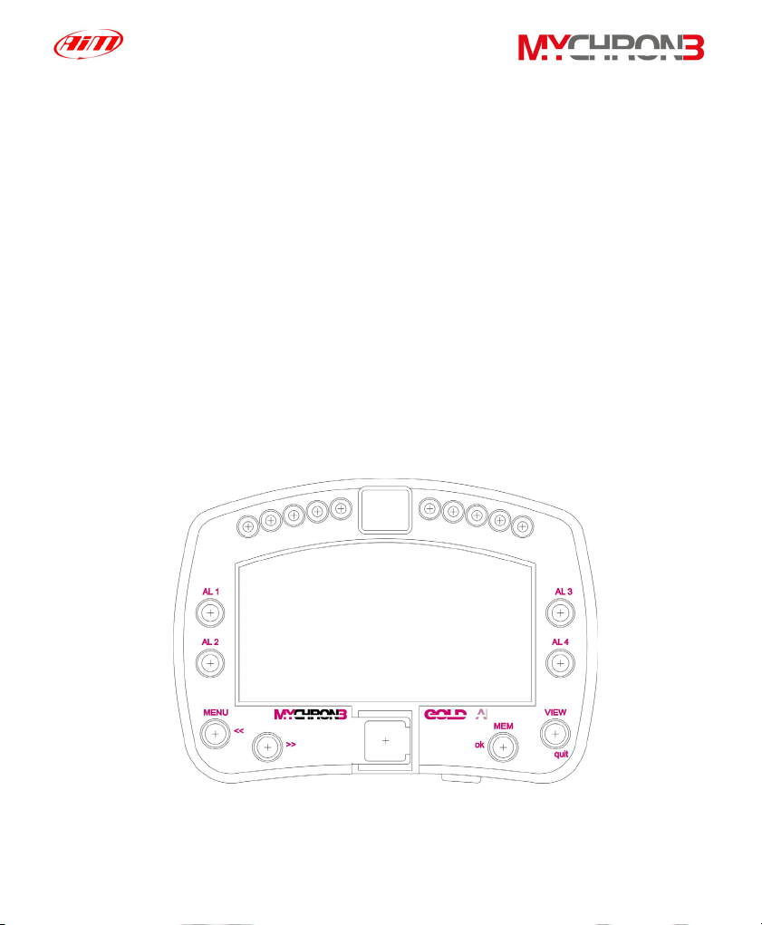
In the following drawing it is represented your MyChron 3 Gold display unit: in
the middle of the picture it is visible the wide display, in the lower part there is the
keyboard, on the left and on the right there are 4 coloured alarm led (labelled from
AL.1 to AL4) and, in the upper part, you can find the gear number display and 10
fully configurable RPM led.
In the following pages it will be described the different parts of MyChron 3
Plus/Gold/Gold XG system.
5
Page 6
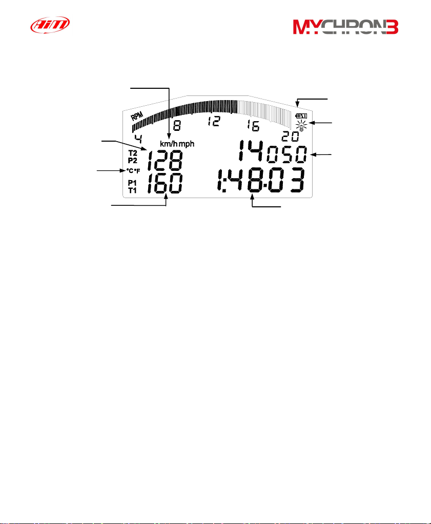
Speed measure
unit
Channels #2 and
#4
Temperature
measure unit
The Display
Low battery
warning
Night Vision
Configurable
display: RPM,
speed, battery
voltage
Channels #1 and
#3
Lap (split) time
The wide display with backlight shows RPM (graphical bar), temperature and
pressure analog inputs, test and lap number and, when the vehicle passes in front
of the beacon, it shows the Lap Time (or Split Time). It is also possible to
configure a second display page (using button VIEW) in order to see the RPM
digital value (as shown in the previous drawing), the vehicle speed (in km/h or
Mph) or the best lap time. When you are not running it is also possible to see the
battery voltage.
The display also shows some small icons, showing the configured Temperature
unit of measure (Celsius [°C] or Fahrenheit [°F]), the Speed unit of measure (km/h
or Mph), the current displayed measure (P1 → P4 for pressures, T1 → T2 for
temperatures, 1 → 4 for custom sensors) the backlight option and the Low Battery
Warning, that appears when the battery voltage is low.
6
Page 7

The Keyboard
MENU
<<
>>
The Keyboard is composed of four push-buttons and it is used to configure the
instrument, to recall recorded data and to clear the internal memory.
The four pushbuttons are used for:
MENU/<<
>>
MEM/OK
VIEW
The gauge automatically switches ON/OFF when the user switches on/off the
Used to enter configuration mode and to switch to previous
configuration option; also used to turn on/off backlight during a test.
Used in configuration to switch to next option; also used to switch
between the 4 analog inputs (temperatures and pressures).
Used to confirm a configuration, to retrieve recorded data and to
see the best lap time.
Used to exit configuration mode without saving, or to switch the
display from “digital RPM” value to “battery voltage”, to “best lap
time” or to “vehicle speed”.
USB
MEM
ok
VIEW
quit
car’s (bike’s) electric switchboard.
To run the system in DEMO MODE, while holding down button MENU/<< and >>,
press button VIEW.
In the middle of the keyboard, protected by a plastic cover, it is located the
instrument’s USB port (used to connect the instrument to a PC).
7
Page 8
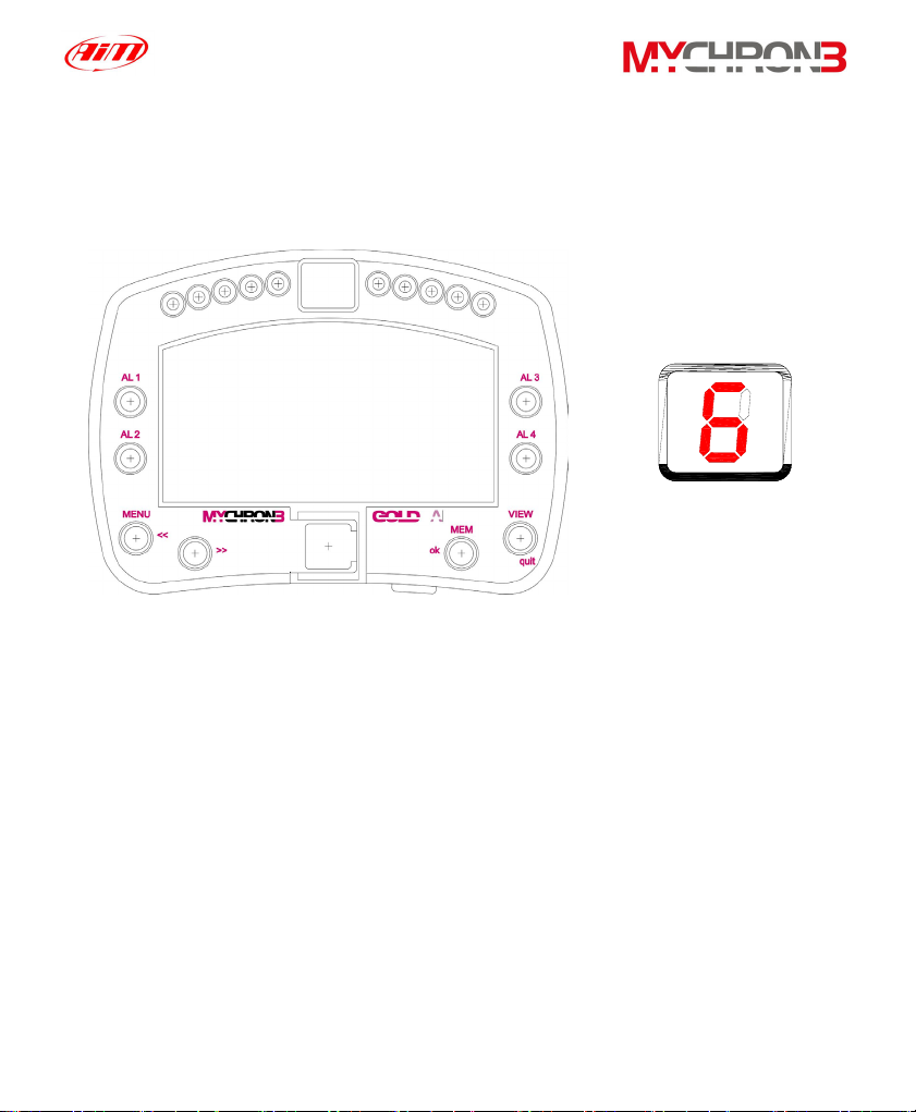
The alarm led and the gear display
In the following picture it is reported a drawing of MyChron 3 Gold Car display
unit.
• The alarm led are placed on the left and right of the main display: on the
left there are the led 1 and 2 and, on the right, there are the led 3 and 4.
The four led are red colored.
• The RPM led are placed in the display unit upper part: this fully
configurable led turn on two-by-two, advising the driver to shift gear. The
4 external led (2 on the left and 2 on the right) are green colored, the 2
middle ones are orange colored and the 4 remaining ones are red
colored.
• The Gear display is placed in the middle of the RPM led. This digital
display shows the current gear number; the instrument is able to display
up to 9 gears.
8
Page 9
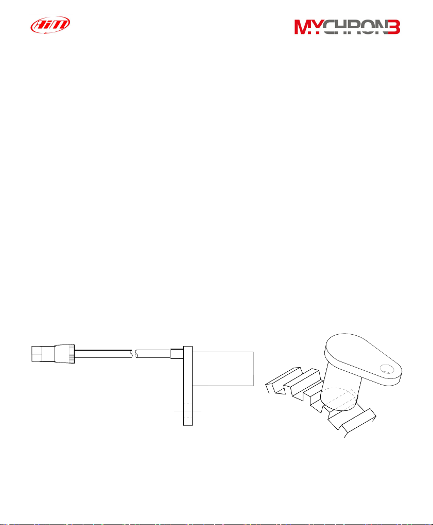
The Speed sensor for CAR installations
MyChron 3 Plus/Gold/Gold XG is equipped with a speed sensor, which allows
the pilot to measure vehicle’s speed.
The wheel speed sensor for gear tooth belongs to the “non contact” devices and it
needs a ferrous metal trigger to pass the sensor face.
The instrument’s measure range is included between 0.5 and 2 mm: the optimum
sensing distance is 1 mm.
Optimum sensor performance is dependent on the following variables, which
must be considered in combination: trigger material, geometry and speed, sensor
trigger gap, magnetic material in close proximity. Please refer to the “Installing the
CAR speed sensor” paragraph for further information.
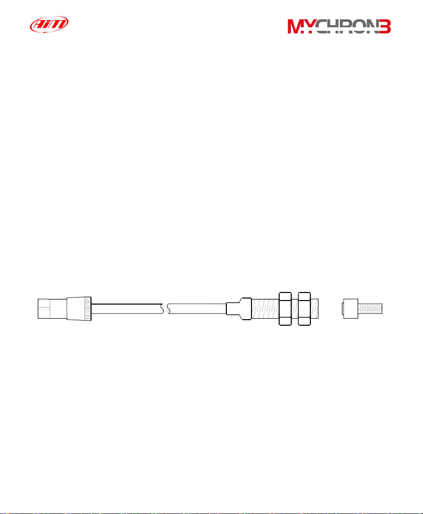
The speed sensor is supplied with an 80 mm long cable.
In the following drawing you can see the gear tooth speed sensor side view (on
the left) and a 3D view (on the right).
9
Page 10
The Speed sensor for BIKE installations
The wheel speed sensor for bike installations belongs to the “magnetoresistive –
non contact” devices and it needs a magnetic metal trigger to pass the sensor
face.
The magnetoresistive speed sensor is a high sensing distance instrument: its
measure range goes from 8 to 15 mm and the optimum sensing distance is
10 mm.
Please refer to the “Installing the BIKE speed sensor” paragraph for further
information.
The speed sensor is supplied with a 1700 mm long cable.
In the following drawing you can see the bike speed sensor and, on the right, the
magnetic trigger (supplied together with the sensor).
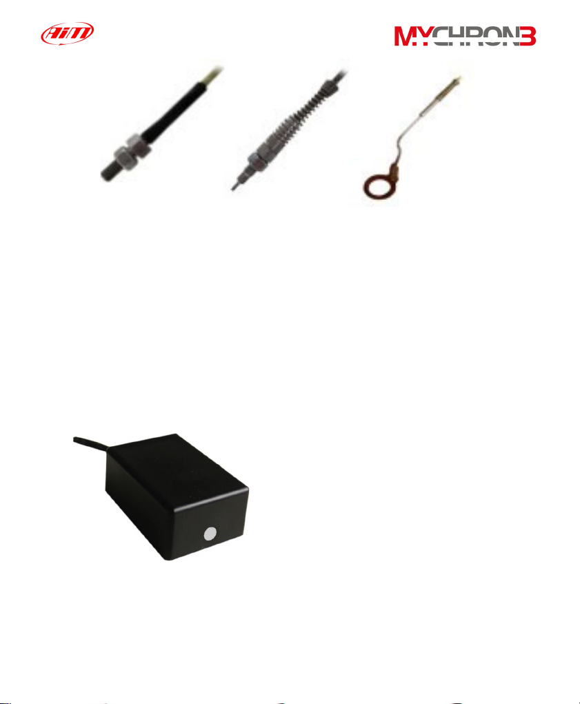
The Temperature sensors
MyChron 3 Plus/Gold/Gold XG supports up to 4 temperature sensors. There are
4 types of temperature sensors that are available for selection or subsequent
purchase:
O - Water thermocouple or thermoresistance: M5 type.
1. H
2
2. EGT - Exhaust gas thermocouple.
3. CHT - Cylinder head thermocouple.
10
Page 11
1
2
3
All temperature sensors are supplied with a 0.25 m long connection cable.
Thermocouple or thermoresistance extension cables are available with lengths
included between 0.5 and 2 m and, on request, as specified dimensions.
The LAP receiver
The infrared lap receiver is used to recognise a signal, called “lap marker”,
emitted from an infrared transmitter (Beacon).
The Infrared receiver has to “see” the
transmitter placed on the trackside, so
remember to install it with the receiver
eye (the grey point in the photo on the
left) pointed to the beacon transmitter.
11
Page 12
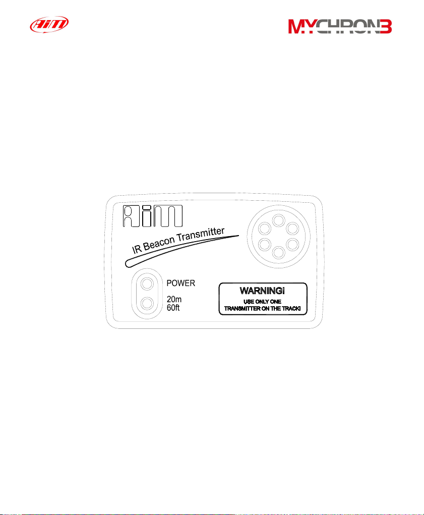
The LAP transmitter (Beacon)
The optical Beacon Transmitter has to be placed on the trackside to mark laps.
Ensure the infrared receiver eye faces the side of the track where the Beacon
has been placed, otherwise the system will not record lap time.
The Beacon transmitter is powered using 8 AA batteries or an external 12V power
cable. If you are using 8 AA batteries, unscrew the back cover of the Beacon
transmitter and place the battery pack into the transmitter casing.
The transmitter has two operating modes: Low power and High power. The Low
Power Mode has to be used when the track is less than 10 meters wide, while
the High Power mode has to be used when the track is wider than 10 meters.
To activate the High/Low Power function, please open the Beacon transmitter
with a corkscrew and place the clip (located directly below where the battery
pack is attached to the beacon transmitter board) either over one of the two
connectors (for low power mode) or over the two connectors (for high power
mode).
12
Page 13
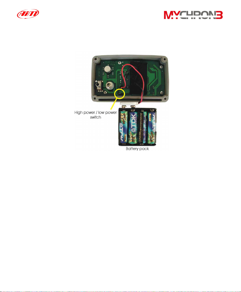
When the Beacon transmitter operates in high power mode, both the power led
lights will light up when the transmitter is turned on.
Please, remember that, in High Power Mode, the transmitter has to be
powered by an external 12 Volts battery.
13
Page 14

How to install MyChron 3 Plus/Gold/Gold XG
Now you can start installing your MyChron 3 Plus/Gold/Gold XG on your
car/bike.
It is recommended to follow these instructions in order to preserve your
instrument and to capture consistent and accurate data.
We remind you that your MyChron 3 Plus/Gold/Gold XG is not equipped with
internal batteries, and so it needs to be powered by an external power source (the
car / bike battery).
The first installation step consists in mounting the Gauge in your car’s
(motorbike’s) cockpit. It is recommended to choose a place where the instrument
will not be in contact with oil or fuel, make sure that the gauge is not installed too
close to heat sources and protect the instrument from vibrations.
In order to correctly measure the lateral g-force using the internal accelerometer
(MyChron 3 Gold only), it is suggested to install the gauge with the display
perpendicular to the vehicle’s speed.
Installing MyChron 3 Gold XG
Your MyChron 3 Gold XG is composed of two separate objects (the display unit
and the Junction box) connected by a pig-tail cable.
It is recommended to choose a place where both the display unit and the Junction
box are not in contact with oil or fuel, make sure that the gauge is not installed too
close to heat sources and protect the instrument from vibrations.
14
Page 15
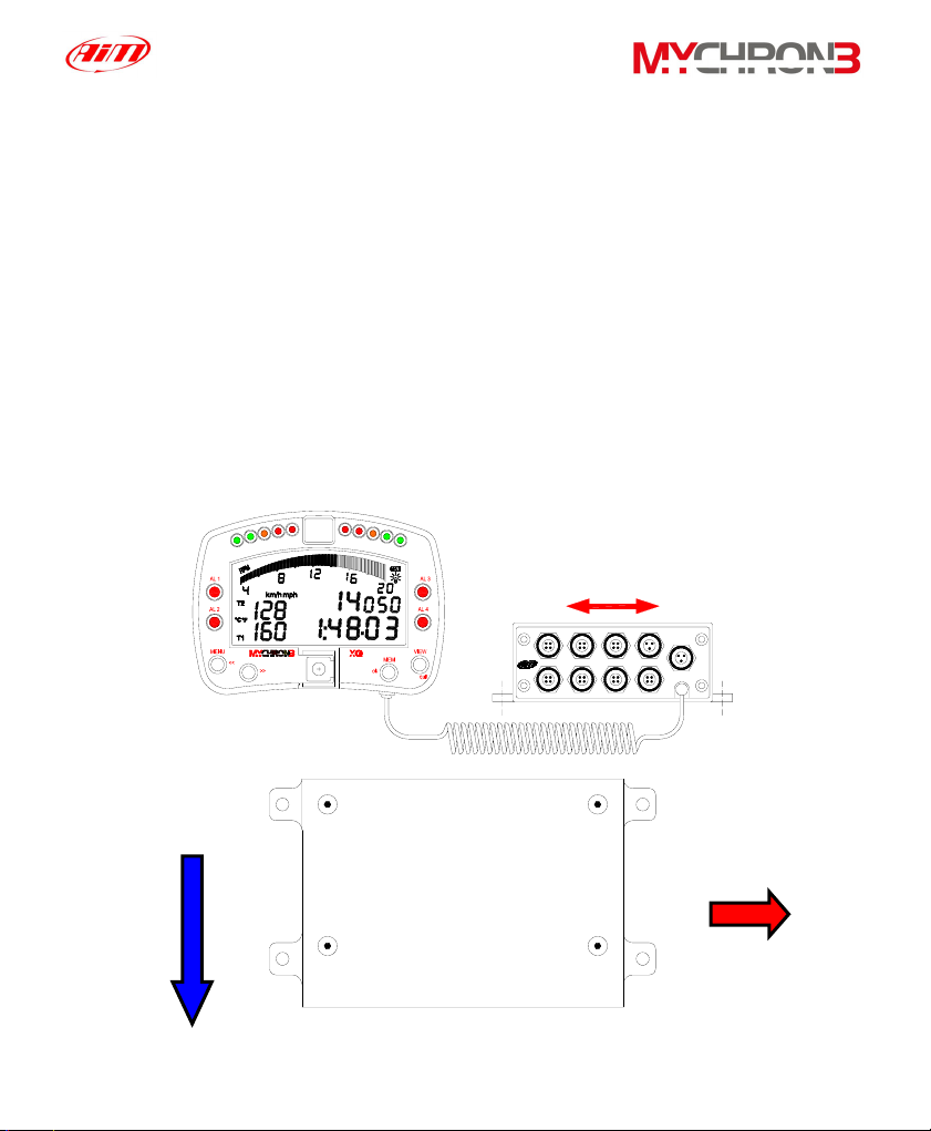
In particular, pay attention when installing the Junction box:
•
Avoid rigid connections between the Junction box and the chassis. It is
suggested to use anti-vibration mountings (Silent Blocks).
•
We remind you that your MyChron 3 Gold XG is not equipped with
internal batteries, and so it needs to be powered by an external power
source (i.e. the car battery).
•
In order to correctly measure the lateral g-force using the lateral
accelerometer (mounted inside the Junction box), it is suggested to install
the gauge with the Junction box’s front panel perpendicular to the car’s
speed, as shown in the following image.
Internal lateral accelerometer
CH1
CH3
CH2
CH4
Power IN
Speed
RPM
Beacon
GEAR
Speed
direction
Junction
Lateral
accelerometer
Box
15
Page 16
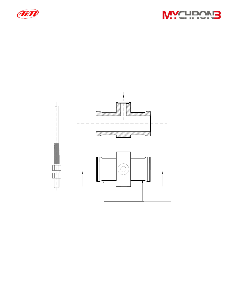
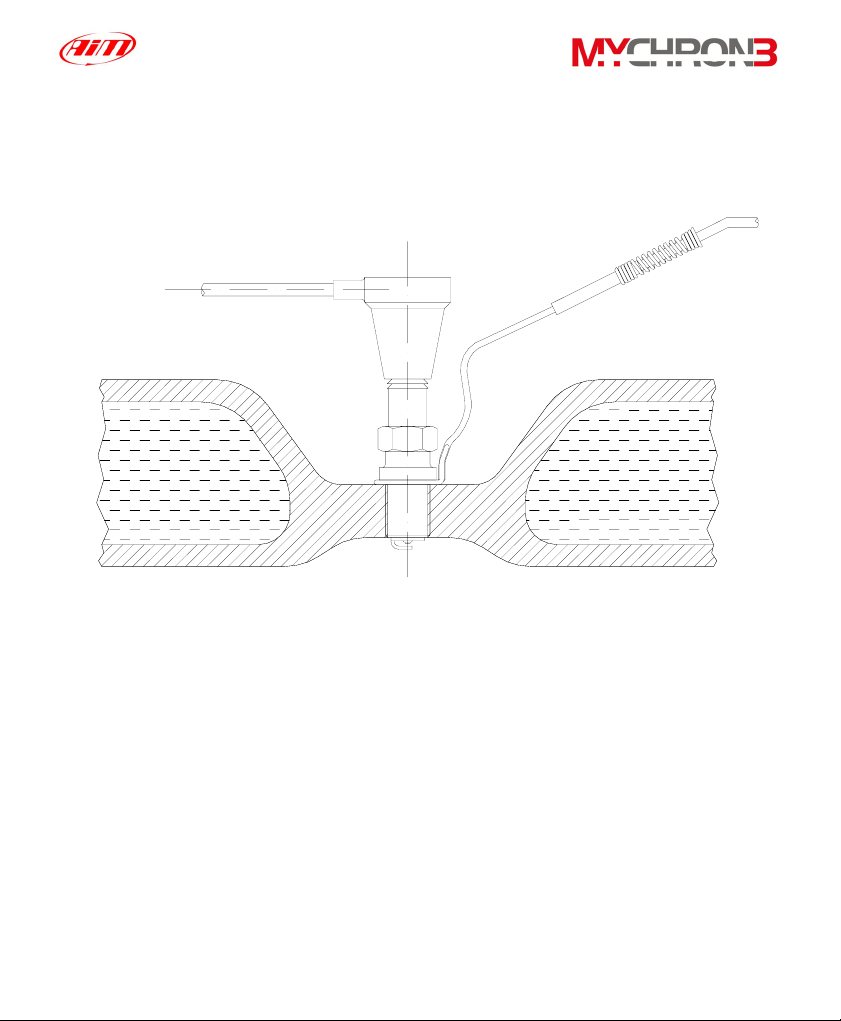
Installing the H2O thermocouple (thermoresistance)
The H
O thermocouple and the thermoresistance can be installed in the inline
2
water fitting (sold separately).
In the following drawing it is represented how to correctly install the water
thermocouple (thermoresistance) for the M5 type.
The water
thermocouple
SEZ A - A
A A
Water thermocouple
must be
placed here
Junction
must be
hanged here
with two
wiring wraps
Installing the EGT thermocouple
The Exhaust Gas Thermocouple (EGT) should be positioned inside the exhaust
header pipe at a distance of 150 mm (5.9 inches) from the exhaust port.
16
Page 17
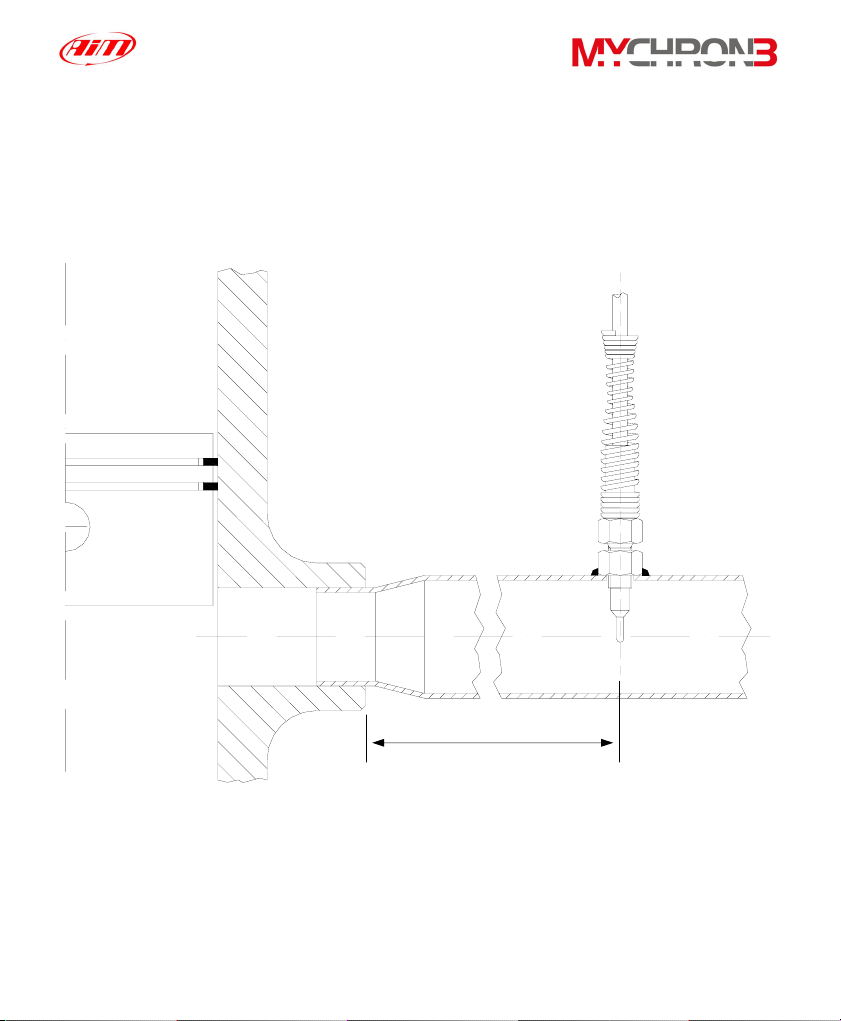
In the following drawing it is represented a correct installation of the EGT
thermocouple.
It is recommended that the probe be inserted between 25% and 50% inside the
exhaust gas header.
150 mm
To install the EGT thermocouple, please follow these instructions:
1. Make a 5 mm (0.2 inches) hole inside the exhaust header;
2. Weld the little nut to the exhaust header in the place where the hole has
been drilled;
17
Page 18
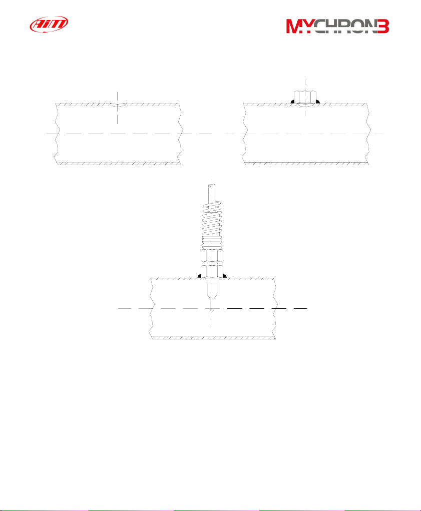
3. Connect the remaining part of the thermocouple and fix it to the exhaust
header by screwing it.
1 2
Weld
3
Installing the under-spark thermocouple
When using a Cylinder Head Thermocouple (CHT) sensor, always remove the
spark plug washer before inserting the spark plug into the sensor.
When tightening and loosening the spark plug, minimise movement of the sensor
to avoid damage.
18
Page 19
y
In the following drawing it is represented the correct installation of the under-spark
thermocouple.
CHT thermocouple
Spark
linder head
C
Installing the “CAR” speed sensor
The wheel speed sensor for phonic wheel belongs to the “non contact” devices
and it needs a ferrous metal trigger to pass the sensor face.
When mounting the sensor, please firmly install it on a self-made iron bracket and
make sure that the distance between the sensor and the phonic wheel is included
between 0.5 and 2 mm (1 mm is the optimum value). Once the sensor has been
installed, please plug the sensor’s Binder connector in your MyChron 3
Plus/Gold/Gold XG.
19
Page 20
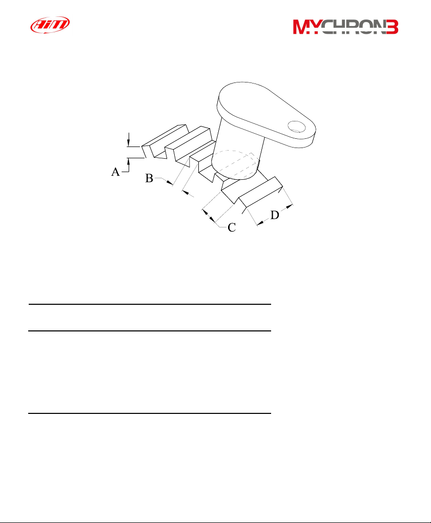
In the following drawing it is reported the speed sensor installation.
In the following table it is reported a short description of the minimum values for
the trigger dimensions A, B, C and D required for a correct sensor’s working.
Description Value (Minimum)
Tooth height (A) 5.06 mm
Tooth width (B) 2.54 mm
Tooth spacing (C) 10.16 mm
Thickness (D) 6.35 mm
In short, optimum sensor performance is dependent on the following variables,
which must be considered in combination: trigger material, geometry and speed,
sensor trigger gap, magnetic material in close proximity.
20
Page 21

Installing the “BIKE” speed sensor
The wheel speed sensor for bike installations belongs to the “magnetoresistive –
non contact” devices and it needs a magnetic trigger to pass the sensor face.
When mounting the sensor, please firmly install it on a self-made iron bracket and
make sure that the distance between the sensor and the magnetic trigger is
included between 15 and 8 mm (10 mm is the optimum value). Once the sensor
has been installed, please plug the sensor’s Binder connector in your MyChron 3
Gold.
How to power the gauge
The gauge must be powered by an external 9-15 VDC power source. Do not
exceed these limits.
Connect the red wire to the battery’s positive pole (+) and the black one to the
negative pole (-).
How to sample the RPM
The RPM signal may be sampled either from the ECU or from the coil.
• • The RPM signal sampled from the ECU is a square wave signal (from 8
up to 50 V);
The RPM signal sampled from the coil is a high voltage RPM input (from
150 to 400 V) and must not be connected on the “RPM from ECU” input
(this event may seriously damage the gauge).
It is also reminded to connect either the RPM signal from the coil or the
RPM signal from the ECU, NOT both (this event creates shortcuts).
21
Page 22

On track
As you power on your MyChron 3 Plus/Gold/Gold XG, some information is
displayed: here they are described in the same order as they appear:
AIM 1_xy
1.
MYC 3 PLUS/GOLD/GOLD XG CAR/BIKE
2.
Firmware version.
Instrument name.
Configuration functions
Before getting started, please configure your gauge in order to get correct
data from your system.
Enter CONFIGURATION MODE (push MENU/<< button) to set the parameters.
Buttons MENU/<< (back to previous option) and >> (forward to next option) are
used to scroll through the configuration menu.
To exit CONFIGURATION MODE and return to MAIN DISPLAY MODE, press
button VIEW.
The parameters you can set in CONFIGURATION MODE are here above
explained in the same order they appear by clicking the MENU/<< button.
22
Page 23

Night Vision
Clear test data
MyChron 3 Plus/Gold/Gold XG display can be set to
backlight display so that it is visible during night racing.
To set the Night Vision ON or OFF, press button MEM/OK
until you see
NIGHT VISION ON/OFF
and then push button MEM/OK. To return to main display
mode press button VIEW. When the Night Vision option is
activated, a light globe will be displayed in the display’s top
right corner.
To activate Night Vision mode during a test, it is enough to
press button MENU/<<.
The backlight setting is stored by the logger: each time the
logger is switched on, the setting used before switching off
the gauge is automatically restored
The “Clear test data” option clears the data stored in system’s
memory.
To run this function, after having entered the
CONFIGURATION MODE, push MENU/<< until you see
CLEAR TEST DATA
Then press button MEM/OK twice to erase data or press
VIEW to quit.
23
Page 24
Beacon
obscuring
time and
split’s number
These 2 functions are fundamental in order to acquire the
correct lap and split time.
The first function is used to set the Beacon’s obscuring time,
which is a time period during which the optic receiver, after
having acquired the lap marker, is “blind” and can’t detect
other lap markers.
The second function, instead, allows the user to set the track’s
split number. In fact, it is possible that a circuit is equipped
with more than one Beacon transmitter along the track:
additional transmitters than the first one installed on the
straight line give “split time”.
In the following paragraph, it is reported three examples of
obscuring time/split’s number configurations.
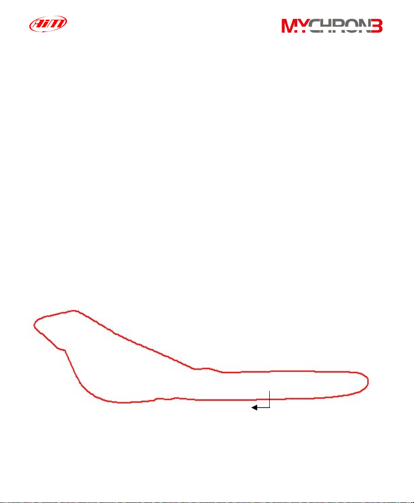
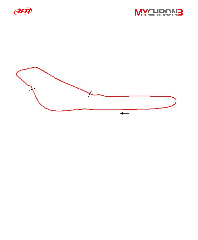
Example 1) The track is equipped with only one lap transmitter
Start/Finish
Lap time 1’ 25”
24
Page 25
• In this case you cannot acquire split times because the track is not
equipped with additional lap transmitters. It is recommended to set the
following values:
o Split’s number = 0;
o Beacon obscuring time: please set a time lower than your best
lap time. In this example, the best lap time is 1’ 25”: you should
set, for instance, 1’ 10”.
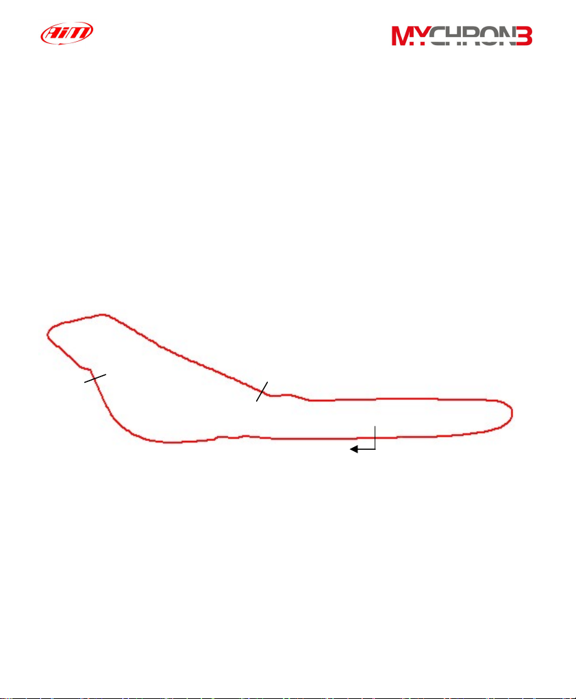
Example 2) The track is equipped with more than one lap transmitter but
you do not wish to capture split times
Intermediate 2:
Time 50”
Intermediate 1:
Time 30”
Start/Finish
Lap time 1’ 25”
• As the track is equipped with more than one transmitter and you do not
wish to capture split times, please set the following parameters:
o Split’s number = 0;
o Beacon obscuring time: please set a time lower than your best
lap time and greater than the time elapsed at the last
25
Page 26
intermediate before the finish line. In this example, you should
set a value included between 50” and 1’ 25”.
Example 3) The track is equipped with more than one lap transmitter and
you wish to capture split times
Intermediate 2:
Time 50”
Intermediate 1:
Time 30”
Start/Finish
Lap time 1’ 25”
• As the track is equipped with more than one transmitter and you wish to
capture split times, please set the following parameters:
o Split’s number = total number of lap transmitters installed on the
track excluded the one installed on the finish line. In this
example, set 2 split’s number.
o Beacon obscuring time: the obscuring time must be lower than
the minimum split time. In this example, as the minimum split
time elapsed is the one from the first intermediate to the second
one (split time 20”), please set the beacon obscuring time to 15”.
26
Page 27

To set the split’s number, after having entered the
CONFIGURATION MODE, push MENU/<< until you see
NUMBER OF SPLITS
Then push MEM/OK to enter EDIT MODE: use button
MENU/<< to change numbers and button >> to change digit.
The blinking number identifies the digit that can be edited.
Press button MEM/OK to save the changes or button VIEW to
discard the changes.
To set the Beacon obscuring time, after having entered the
CONFIGURATION MODE, push MENU/<< until you see
Obscuring time
Now push MEM/OK to enter EDIT MODE, then press button
MENU/<< until the correct number of splits appears on the
display’s lower right corner. The obscuring time can be set up
to a maximum value of 100 seconds.
Press button MEM/OK to save the changes or button VIEW to
Distance and
total time
discard the change
This function shows the total instrument working time (in hours
and minutes) and the distance covered by the vehicle (in km
or in miles) during a test.
To run this function press button MENU/<< until you see
TOTAL RUNNING
27
Page 28

To delete the total working time and the distance covered by
the vehicle, please press twice button MEM/OK; press VIEW,
instead, if you do not wish to delete these information.
It is reminded that this function computes only time and
distance corresponding to a single test: if you wish to know
the total distance covered by the vehicle, please run function
“Odometer”.
Odometer
Gears
calibration
This function computes the total distance covered by the
vehicle during all the tests made.
To run this function press button MENU/<< till you see
ODOMETER
Unlike the previous function, this parameter cannot be erased.
Your gauge is able both to detect the engaged gear by using
an on-board sensor (for those vehicles equipped with a sensor
installed inside the gearbox) or by calculating them (using an
algorithm based on engine’s RPM and Speed). If no sensor is
installed and the driver does not wish to see the gear number
on the display, the gauge allows the user to disable the gear
channel.
To run this function press button MENU/<< until you see
GEAR CALIBRATION
Press button NEXT/MEM to activate one of the gears
calibration functions here above described:
28
Page 29

GEAR computed
Gear is disabled
Gear with sensor
1) Compute gears
Once selected the “Gear computed” option, pressing button
MEM/OK, it will appear the following text:
Higher gear
Enter the higher gear number (up to 9) using button
MENU/<<; then press button MEM/OK to save the changes or
VIEW to discard them.
Once set the higher gear number, you have to run at least 2
track laps in order to let the gauge “learn” the threshold values
for the different gears.
It is strongly recommended to run these laps engaging all
gears. If a gear is not engaged during these “learning
laps”, the gauge will not be able to show all gears.
During these “learning laps”, no gear value will be shown.
Once finished the “learning laps”, return to the pit lane and,
before switching the gauge off, please ensure that the vehicle
is completely stopped (i.e. the speed value is 0). It is reminded
that there is no problem if you switch off the gauge together
with the engine (MyChron 3 Plus/Gold/Gold XG with firmware
1.55 or later).
29
Page 30

Case 1: if you turned off the engine and stopped the vehicle
without switching off the gauge, the red led AL 1 starts
blinking, informing the driver that the gauge is calculating the
threshold values.
Case 2: otherwise, if you switched off the gauge together with
the engine, the gear calculation procedure starts once you re-
switch on the gauge (the red led AL 1 blinks).
Once the red led AL 1 stops blinking, the gear calculation
procedure is completed: now you will be able to see the gear
value inside the gauge’s gear display.
If the gear values displayed do not correspond to the engaged
gears, please repeat the gear calibration procedure.
It is reminded that the threshold values are saved in the
gauge’s internal memory and the user will not have to
calculate them each time the gauge is switched on.
The algorithm is able to detect the engaged gear as it
calculates the engine’s RPM vs. speed ratio. If the speed is
acquired from a non-driving wheel, the algorithm may return
incorrect gear values.
The RPM vs. speed ratio is directly proportional to the
transmission/gearbox ratio and to the wheel circumference: if
one of them (or both) is changed, the gear calibration
procedure may have to be repeated.
30
Page 31

2) Gear is disabled
Select this option if you do not have a gear sensor installed
inside the gearbox or you do not wish to see the gear number.
3) Gear with sensor
Once selected the “Gear with sensor” option, you will see the
following sentence
INSERT GEAR
Meanwhile, in the gear display, you will see the gear number
blinking.
Please engage the “neutral gear” and then press button >> to
step to next gear calibration. The procedure to be followed is
similar to what has just been explained: you have to engage
the next gear and to press the >> pushbutton.
The gauge supports gearboxes with a gear number up to 9.
If your vehicle’s gearbox has a gear number lower than 9
(typical values are 5, 6 or 7 gears), once you have engaged
the last gear you have to press button MEM/OK to save the
current calibration.
To restart the calibration procedure, press button MENU/<<.
To disable the gear channel, press button MEM/OK when you
see the number 0 blinking in the gear display; it will also
appear the following sentence
GEAR IS DISABLED
To exit calibration mode without saving press button VIEW.
31
Page 32

Shift lights
configuration
This function allows the user to configure the 10 colored led
placed in the right upper part of the instrument’s display.
These led get switched on when the engine reaches a set
RPM value, indicating the pilot to shift gear.
To run this function, press button MENU/<< until you see
SHIFT LIGHT
By pressing button MEM/OK you will switch on the first led on
the left and the first one on the right, both green colored, and it
will appear the RPM value correspondent to that led lighting.
Press MEM/OK to enter EDIT MODE: use button MENU/<< to
change numbers and button >> to change digit. The blinking
digit identifies the digit that can be edited.
When the correct RPM value is displayed, press button
MEM/OK to save the changes and to step to second led
configuration; otherwise press button VIEW to quit without
saving.
The 10 led are colored in the following way: the first two on
the left and the first two on the right are green, the middle
ones are orange and the remaining ones led are red colored.
th
When the engine reaches the RPM value set for the 5
led, all
the 10 led will start flashing, advising the pilot to shift gear.
The RPM value can be set between 0 and 29999; if you set an
alarm value of 0, that led will be disabled.
32
Page 33

Wheel
circumference
Phonic
This function sets the wheel circumference (in mm or in
inches).
This parameter is fundamental to correlate the wheel’s
angular speed and the vehicle speed.
To run this function press button MENU/<< until you see
WHEEL CIRCUMFEREN
Then push MEM/OK to enter EDIT MODE: use button
MENU/<< to change numbers and button >> to change digit.
The blinking digit identifies the digit that can be edited.
The wheel circumference value can be set in a range included
between a minimum value of 0 and a maximum one of
9999 mm (0 and 399.99 inches).
When the correct circumference value has been set, press
button MEM/OK to save changes or press button VIEW to quit
without saving.
This option allows the user to set the phonic wheel’s teeth
wheel’s teeth
number
number in order to measure the wheel’s angular speed.
The speed sensor, passing by a gear tooth, generates an
electric pulse which gets acquired by the instrument: if the
phonic wheel is made up of just one tooth, the instrument will
measure one pulse per lap, while, if it is made up of more than
one tooth, the number of pulses per lap will be greater than
one.
33
Page 34

In order to capture the correct wheel’s angular speed, it is
necessary to set the correct teeth number.
To run this function press MENU/<< until you see
PULSES ON WHEEL
Then push MEM/OK to enter EDIT MODE: use button
MENU/<< to change numbers and button >> to change digit.
The blinking digit identifies the digit that can be edited.
This parameter is included between a minimum value of 0 and
a maximum of 199.
Press button MEM/OK to save the changes and button VIEW
to quit without saving.
Max RPM
value
This function sets the maximum scale for the graphical RPM
display and the maximum acceptable RPM value acquired by
your MyChron 3 Plus/Gold/Gold XG.
MyChron 3 Plus/Gold/Gold XG has seven levels for the
RPM scale: 8,000 / 10,000 / 12,000 / 16,000 / 20,000 / 22,000
and 25,000 RPM.
To run this function, after having entered the
CONFIGURATION MODE, push MENU/<< until you see
MAX RPM VALUE
Then push MEM/OK to enter EDIT MODE and use buttons
MENU/<< or >> to scroll between the seven standard RPM
values. When the required RPM value is displayed, press
button MEM/OK to save the changes or button VIEW to quit.
34
Page 35

Spark for Revs
Temperature
unit of
measure
This option represents the number of spark signals, acquired
from the coil or the ECU, per engine revolution.
To set the Spark for Revs, after having entered the
CONFIGURATION MODE, push MENU/<< until you see
SPARK FOR REVS
Then push MEM/OK to enter EDIT MODE and use buttons
MENU/<< or >> to scroll between six standard values: x1, x2,
/2, /3, /4 and /6. For instance, the correct value for a 4 strokes
4 cylinder engine is /2.
Press button MEM/OK to save the changes or button VIEW to
discard the changes.
This function sets the temperature’s unit of measure: the user
may choose between Celsius [°C] and Fahrenheit [°F]
degrees.
To run this function, after having entered the
CONFIGURATION MODE, push MENU/<< until you see
FAHRENHEIT/CELSIUS
Then push MEM/OK to enter EDIT MODE and use button
MENU/<< till you don’t see the proper Temperature unit of
measure, and confirm it pushing MEM/OK. Press button VIEW
to discard the changes.
The symbols °C or °F will appear on the left of the display.
35
Page 36

Speed unit of
measure
Pressure unit
of measure
This function sets the speed’s unit of measure; the user can
choose between km/h and Mph.
To run this function, after having entered the
CONFIGURATION MODE, push MENU/<< until you see
SPEED UNIT
Then push MEM/OK to enter EDIT MODE and use button
MENU/<< till you don’t see the proper unit of measure.
To confirm your choice push button MEM/OK; press button
VIEW to discard the changes.
This function sets the speed’s unit of measure; the user can
choose between Bar and PSI.
To run this function, after having entered the
CONFIGURATION MODE, push MENU/<< till you see
Pressure unit
Then push MEM/OK to enter EDIT MODE and use button
MENU/<< till you don’t see the proper unit of measure.
Message
language
To confirm your choice push button MEM/OK; press button
VIEW to discard the changes.
MyChron 3 Plus/Gold/Gold XG text can be displayed in
English, Italian, German or French.
To run this function, after having entered the
CONFIGURATION MODE, push MENU/<< until you see
MESSAGE LANGUAGE
36
Page 37

Firmware
Then push MEM/OK to enter EDIT MODE and use MENU/<<
or >> to change language.
Press button MEM/OK to save the changes or button VIEW to
discard the changes.
This function shows three numbers, which represent,
version
respectively, the firmware version, the firmware upgrade date
and the gauge’s serial number.
To run this function, after having entered the
CONFIGURATION MODE, push MENU/<< until you see
FIRMWARE version
The firmware management window is organized on two
different rows: in the upper one it is shown the firmware
version, on the left, and the firmware upgrade date, on the
right (dd/mm/yy). In the lower row, instead, it is shown the
gauge’s serial number.
Utility functions
Once configured your system, you are ready to manage the data acquired with
your gauge. MyChron 3 Plus/Gold/Gold XG records RPM, 4 analog inputs
(pressures or temperatures for Plus version, pressures, temperatures,
potentiometers, Lambda sond for the Gold/Gold XG ones), speed, gear number,
lateral g-force (Gold CAR and Gold XG versions) or Gyroscope (Gold BIKE
versions) at a maximum sampling rate of 200 Hertz (200 times per second) per
channel. These data can be retrieved at a later stage for analysis.
37
Page 38

MyChron 3 Plus/Gold/Gold XG segments data for a session as a test and each
test includes the laps completed in that session. To begin recording a new test
you may switch off your instrument and then switch it back on, or you may press
the MEM button: once you exit the “retrieve data from memory” function, your
MyChron 3 Plus/Gold/Gold XG will record data in a new test session.
Viewing data
MyChron 3 Plus/Gold/Gold XG will display “Test 01” or the
while driving
current test number if memory has not been cleared, and “Lap
001” once the infrared receiver passes the beacon transmitter.
If the system has been configured to capture back segments
using the number of splits option, the system will display “Split
Number x”, up to the number of splits selected. Once the
system records times for each split, the final segment is
displayed as a completed lap.
At the same time the system displays the time gap between the
current split time and the split time of the previous lap.
When the system records the best lap time for a test, the text
BEST LAP TIME
will appear on the display under the RPM graphical bar.
By pressing button VIEW it is possible to visualize, instead of
lap time, the RPM digital value or vehicle’s speed.
The four analog inputs are shown on the left of the display: the
system will display, as a default, channels number 1 and
number 2.
38
Page 39

By pressing button >> it is possible to shift your MyChron 3
Plus/Gold/Gold XG to another display page, where you can
see the other two analog inputs.
Moreover, together with the channel’s values, the display shows
two further information:
• an icon (T or P), to identify the sensor type: “T” stands
for “temperature sensor”, while “P” stands for “Pressure
sensor”. If you connected a temperature or pressure
“custom sensor” (please refer to paragraph “Customize
sensor”), the display will show the corresponding icon
(T or P). Otherwise, if you connected a generic “custom
sensor” (i.e. a custom sensor which does not belong to
the temperature/pressure sensors), no icon “T” or “P”
will be shown.
• A number (from 1 to 4), which identifies the sensor
number.
For instance, if you connected a temperature sensor on channel
1, a “generic custom sensor” on channel 2, a pressure sensor
on channel 3 and another temperature sensor on channel 4,
your MyChron 3 Plus/Gold/XG will show, in the first display
page, “T1” for channel 1 (it is the first temperature channel),
“1” for channel 2 (it is the fist “generic custom sensor”), “P1”
for channel 3 (it is the first pressure channel) and “T2” for
channel 4 (it is the second temperature channel).
39
Page 40

When the gauge is switched on, the display shows the last
selected measures during race time: for instance, if you were
visualizing speed, temperature 1 and temperature 2, the display
will show these channels. Moreover, the gauge saves the
backlight status (switched on or off) and restores the previously
saved status when the gauge was switched on.
Your gauge’s memory is divided into two separate parts. In the
first one it is stored the sampled channels and it has 45 minutes
(MyChron 3 Plus) or 3 hours (MyChron 3 Gold/Gold XG)
maximum storage time. In the second one it is only stored the
lap times, the split times and the maximum / minimum values of
speed, RPM and channels number 1 and 2 for each lap.
If during race the “sampled channels” memory fills up, the
following text will be displayed:
Measures mem full
The gauge will keep on recording the lap/split times and the
channels’ maximum/minimum values.
If, otherwise, the “maximum/minimum values” memory fills up,
the following text will be displayed:
Lap Memory full
The gauge will keep on recording the channels’ values.
When both memories are full, the following text will be
displayed:
Memory full
40
Page 41

In this situation, the data logger works only as a “dash” and
does not samples any more data. It is recommended to
download the data stored in the gauge’s memory and to clear it.
When a test is completed, the system displays the last lap number and last lap
time. Using button MEM/OK you will access the data stored in system’s memory.
Let’s now see how to retrieve data after the completion of a test.
Viewing data
To view the data for the lap with the best lap time, press
per best lap
time
MEM/OK while in general display mode.
The best lap time is displayed for the most recent test. The
lap time will be flashing, signaling that this is the best time for
the current test.
The instrument will also show the test and lap number and
the maximum values corresponding to channels number 1
and 2 for the current lap.
If button MEM/OK is pressed a second time, it will appear the
minimum values corresponding to channels number 1 and 2
and minimum RPM for the best lap.
If you press button VIEW in one of the two previously
described display pages, the display will show the maximum
values corresponding to speed and to channels number 1
and 2.
Press button VIEW again to quit replay mode or press button
MEM/OK to view the minimum values corresponding to speed and
to channels number 1 and 2.
41
Page 42

View other
completed
lap data
To view completed lap data, while in general display mode,
press button MEM/OK to view the best lap time. Then press
button MENU/<< to view a previous lap or button >> for a
following lap. If you have configured your MyChron 3
Plus/Gold/Gold XG to capture splits, buttons MENU/<< and
>> will also scroll through the split times within each lap.
To retrieve previous test data (when more than one test has
been recorded) press button MENU/<< until the required test
and lap details (or split details) appear on the display.
Buttons MEM/OK and VIEW will allow you to switch between
the different display pages, as previously described in the
“Viewing data per best lap time” paragraph.
Maintenance
Your MyChron 3 Plus/Gold/Gold XG does not require any special
maintenance.
Provided adequate care is taken with the display unit and components, the only
maintenance will be to upgrade the firmware when upgrades are released by
Aim (periodically check www.aim-sportline.com
).
Upgrading
the firmware
To upgrade the firmware, please visit to our website
www.aim-sportline.com
and download the latest firmware
version. The file you have to download is an EXE file, and it is
called “FIRMUP.EXE” (FIRMware UPgrade).
42
Page 43

Connect MyChron 3 Plus/Gold/Gold XG to your PC using the
USB cable furnished as equipment.
Now you can launch the FIRMUP file by double-clicking on it
and the system will automatically upgrade your instrument’s
firmware.
43
Page 44

MyChron 3 Plus/Gold/Gold XG and the computer
MyChron 3 Plus/Gold/Gold XG is equipped with an internal non volatile flash
RAM memory (512 kbyte for Plus version and 2 Mbyte for Gold/Gold XG ones)
which guarantees the capacity to record up to 315 laps and a total amount of 45
minutes (Plus version) or 3 hours (Gold/Gold XG ones) full analog inputs
record.
MyChron 3 Plus/Gold/Gold XG has been designed and developed to be
interfaceable with a PC: through an USB cable it is possible to connect the
gauge to a PC in order to both download the data stored in memory and
configure your instrument.
Aim reminds all MyChron 3 Plus/Gold/Gold XG owners that, for a correct,
complete and easier instrument configuration, it is absolutely
necessary to
use a PC and the software Race Studio 2.
This software has been properly developed by Aim in order to interface all its
products (Drack, EVO 3, MyChron 2, MyChron PRO, Dash ST1, MyChron 3
standard/Plus/Gold) with the PC.
It is reminded that the new software installation does not either cancel or
influence the functionalities of Race Studio 1. Once installed the program, the
user will be able to choose if to use the new software even with his old Aim
products (all supported by Race Studio 2) or if to keep on using the previous
program. It is also reminded that Aim newest products (MyChron 3, MyChron 3
Plus/Gold/Gold XG and Dash ST1) are only supported by Race Studio 2.
44
Page 45

In the following pages it will be shown how to install the software on your
PC and how to correctly configure your MyChron 3 Plus/Gold/Gold XG by
using a PC.
Software installation
Inside MyChron 3 Plus/Gold/Gold XG packaging you will find a CD containing
Race Studio 2, software properly developed to download and analyse the data
stored in your MyChron 3 Plus/Gold/Gold XG memory.
To install the software, insert the CD inside the CD-ROM drive: if the autorun
option is enabled (most of cases), the software installation will automatically
start, otherwise click twice on the SETUP icon.
st
The 1
installation language choice. Through a pop-up menu it will be possible to
choose the preferred language.
screenshot that will appear on your PC’s monitor concerns the
It is reminded that the installation language choice does not entail the software’s
working with only that language.
45
Page 46

If on your PC you have installed a previous version of Race Studio 2, it will
appear the following screenshot:
It is possible to choose whether to Remove the previous version or to Install the
new release. By choosing this second option, the software will automatically
uninstall the previous version and install the new one.
Otherwise, if you do not have older versions of Race Studio 2 on your PC, it will
appear the standard installation window:
46
Page 47

By using button Browse, it is possible to choose the software installation folder: if
you click on the Next button without choosing the installation folder, the software
will be installed in the default folder “X:\Program files\AIM”, where “X” represents
the Hard Drive in which you installed the operative system.
The following screenshot is the final one: please click on Finish button and, then,
run the program.
To run the program, click twice on Race Studio 2 icon, located directly on your
computer desktop, once the installation has finished.
To uninstall Race Studio 2 from your computer, please insert the CD-Rom
containing the software inside the CD-ROM drive and run the installation
procedure. It will appear a dialog box where the user will be allowed to “Remove
Race Studio 2” or to “Install a new release of Race Studio 2”. Please, select the
first option and press “Next” button: Race Studio 2 will be automatically
removed from your computer.
47
Page 48

If you wish to update Race Studio 2, please connect to our website
www.aim-sportline.com and go to “Download” page, where it is possible to
download the latest updates. To install the update, click twice on the downloaded
file and follow the instructions you see on your PC’s monitor.
Race Studio 2 program has been designed and developed to guarantee the
maximum working reliability and its proper working has been tested with
the following operative systems: Microsoft Windows 98 ™, Windows
2000 ™, Windows Me ™, Windows Xp ™. Microsoft Windows 95 ™,
Windows NT ™ and other operative systems (Linux, Unix, Macintosh ™)
are not supported.
If you have troubles during installation or normal working time, please check out
our website or contact Aim.
Installing the USB drivers
Please, read carefully these instructions in order to correctly install the
USB drivers: an incorrect installation may cause system’s malfunctions.
To connect your MyChron 3 Plus/Gold/Gold XG to the PC’s USB port, please
use the USB cable furnished as equipment.
When the PC and the instrument are switched off, connect your MyChron 3
Plus/Gold/Gold XG to the PC’s USB and then switch on both computer and
MyChron 3 Plus/Gold/Gold XG (it is suggested to switch on before the PC and
later on the gauge).
48
Page 49

During restart time, the operative system will recognize a new hardware and will
ask you to install the proper driver, driver that is included either in Race Studio 2
installation CD-ROM or in the “X:/Program files/AIM/USB_DRIVER” folder on
your PC”.
The driver file name is WDUSB522.inf.
In the following pages it will be reported two examples concerning the USB
drivers’ installation for the Microsoft Windows 98 ™, Microsoft Windows
2000 ™ and Microsoft Windows XP ™ operative systems.
How to install the USB Driver for Windows 98 ™:
1. Press [ Next ] button when the “Add new Hardware wizard” window
appears.
2. Select [ Search for the best driver for your device ] and press the [ Next ]
button again.
3. Place the Race Studio 2 disk in the computer’s CD-ROM drive if it is not
already there.
4. If the autorun option is enabled the system will try to install
Race Studio 2. As you have already installed it, please exit installation
menu. If the autorun option is enabled, go directly to next installation
step.
5. Place a check beside [ CD-ROM drive ] and click the [ Next ] button.
6. Click the [ Next ] button again.
7. The installation software has to search for WDUSB522.inf.
8. Click the [ Finish ] button once reached the end of the installation.
9. Restart the computer if prompted.
49
Page 50

How to install the USB Driver for Windows 2000 ™:
1. Press [ Next ] button when the “Found new Hardware wizard” window
appears.
2. Select [ Search for a suitable driver for my device ] and press the [ Next ]
button again.
3. Place a check beside [ Specify a location ] and click the [ Next ] button.
4. Browse the path until you find the driver file WdUSB522.inf located in
the directory X:\Program files\AIM\USB_DRIVER.
5. Click [ Next ] when the correct driver has been selected.
6. Click [ Yes ] if the “Digital Signature Not Found” window appears.
7. Click the [ Finish ] button once reached the end of the installation.
8. Reboot the system in order to install the Virtual Device driver.
9. Press [ Next ] button when the “Found new Hardware wizard” window
appears.
10. Select [ Search for a suitable driver for my device ] and press the [ Next ]
button again.
11. Place a check beside [ Specify a location ] and click the [ Next ] button.
12. Browse the directory path until you find the driver wd_virtual.inf, located
in the directory X:\Program files\AIM\USB_DRIVER, and then click [OK].
13. Click [ Next ] when the correct driver has been selected.
14. Click [ Yes ] if the “Digital Signature Not Found” window appears.
15. Click the [ Finish ] button once reached the end of the installation.
16. Restart the computer if prompted.
50
Page 51

How to install the USB Driver for Windows XP ™:
1. Press [ Next ] button when the “Found new Hardware wizard” window
appears.
2. Select [ Install from a list or specific location (Advanced) ] and press the
[ Next ] button again.
3. Place a check beside [ Include this location in the search ] and click the
[ Browse ] button.
4. Browse the path until you find the driver file WdUSB522.inf located in
the directory X:\Program files\AIM\USB_DRIVER.
5. Click [ Next ] when the correct driver has been selected.
6. Click [ Yes ] if the “Digital Signature Not Found” window appears.
7. Click the [ Finish ] button once reached the end of the installation.
8. Reboot the system in order to install the Virtual Device driver.
9. Press [ Next ] button when the “Found new Hardware wizard” window
appears.
10. Select [ Install from a list or specific location ] and press the [ Next ]
button again.
11. Place a check beside [ Include this location in the search ] and click the
[ Browse ] button.
12. Browse the directory path until you find the driver wd_virtual.inf, located
in the directory X:\Program files\AIM\USB_DRIVER, and then click [OK].
13. Click [ Next ] when the correct driver has been selected.
14. Click [ Yes ] if the “Digital Signature Not Found” window appears.
15. Click the [ Finish ] button once reached the end of the installation.
16. Restart the computer if prompted
51
Page 52

If the USB drivers have been correctly installed, when your MyChron 3
Plus/Gold/Gold XG is switched on, in your PC’s Device management window
(click Start \ Settings \ Control Panel \ System \ Device management) you will
find the voice HID (Human Interface Device) Class and, in subnode, AIM
logger, as shown in the following screenshot.
USB drivers troubleshooting
In this paragraph it will be described the possible solutions to the mostly common
USB drivers installation troubles encountered.
1. Once connected MyChron 3 Plus/Gold/Gold XG to a switched on PC,
the automatic USB drivers installation does not start:
52
Page 53

a. Control that the instrument is correctly plugged in the PC’s USB
port.
b. Verify that both PC and MyChron 3 Plus/Gold/Gold XG are
switched on.
c. If MyChron 3 Plus/Gold/Gold XG does not turn on, verify that
the external battery charge status is good.
d. If the instruments switches on but the automatic USB drivers
installation does not begin, try to plug the USB cable into another
USB port (if a second USB port is available).
e. If available, try to use another USB cable to plug MyChron 3
Plus/Gold/Gold XG in a PC’s USB port.
2. The automatic USB drivers installation starts but the USB driver is not
properly installed:
a. Control your PC’s Control Panel (click Start \ Settings \ Control
Panel \ System \ Device management): if you see a voice like
Unknown Peripheral or Unknown USB device with a yellow
question mark (or a red cross), please select that voice and
remove it (click the mouse right button and select the “Remove”
option). Then switch off your MyChron 3 Plus/Gold/Gold XG,
unplug the USB cable from the PC’s USB port, re-plug the USB
cable in the PC’s USB port and repeat the previously described
installation procedure.
53
Page 54

b. If you see a yellow question mark again, please select the voice
and, instead of removing it, click on the “Property” option; then
choose the “Driver” tab and finally select the “Driver Update”
option. It is now possible to repeat the installation procedure
described in the “How to install the USB Driver for Windows”
paragraph. Please remember to specify the correct path for the
USB drivers, which is the Race Studio 2 CD-ROM drive.
3. In case your PC has not been able to automatically recognize your
MyChron 3 Plus/Gold/Gold XG or the two procedures previously
described had not succeeded in solving your problems, you have to install
the driver manually as here above explained:
• Go to Control panel window.
• Select the “New Hardware” icon.
• Click twice button “Next”.
• Place a check beside “No, I want to select the hardware from list”.
54
Page 55
• Select “HID class” (or “Human Interface Device”).
• Specify the correct path for the USB driver (i.e. Race Studio 2 CD-
ROM drive).
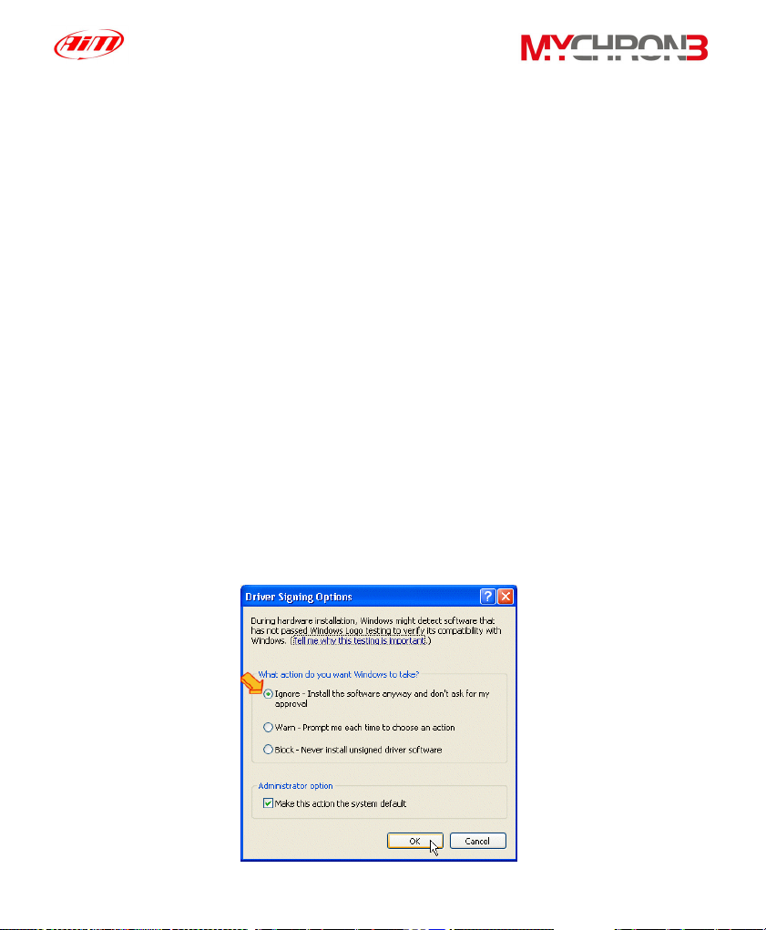
4. The USB driver WDUSB522 does not have a “digital signature”. In some
cases (very rare) Windows XP ™ or Windows 2000 ™ operative
systems have some default settings which do not allow the driver
WDUSB522 to be installed. These settings may be removed following this
procedure:
• Go to Control panel window.
• If you have a Windows XP ™ operative system, select the
“Performance and maintenance” option.
• Click the “System” button (both for Windows XP ™ and 2000 ™).
• Select the “Hardware” flag and, then, press button “Driver signing”.
• Select the “Ignore” option and press button “OK”, as showed in the
following image.
55
Page 56

Configuration via software
For a correct, complete and fast MyChron 3 Plus/Gold/Gold XG
configuration, it is absolutely
necessary to use a PC and the software Race
Studio 2.
The “via software configuration” allows the user to set some parameters that
cannot be set using the keyboard. For instance, the temperature sensors
(thermocouples, thermoresistances, VDO sensors) or the pressure ones, cannot
be set via keyboard and so, if you wish to measure temperature or pressure, you
have to configure your MyChron 3 Plus/Gold/Gold XG using Race Studio 2.
Moreover, if you bought a MyChron 3 Gold/Gold XG and you wish to measure
the lateral g-force (or the gyroscope input), in order to create a track map, you
have to autocalibrate the gauge via software.
Before starting the via software configuration, it is reminded to install Race
Studio 2 and the USB drivers, as mentioned in the previous chapter. It is
also reminded that, before configuring the instrument, you have to connect
it to a PC and to switch it on.
Once launched the program, by double-clicking on the Race Studio 2 icon on
your PC’s desktop or by selecting the Race Studio 2 shortcut in your PC’s Start
toolbar, it will appear the software’s main window, reported here above:
56
Page 57

On the left of the window you may see the icons corresponding to all the Aim
instruments supported by Race Studio 2: Dash ST1, MyChron 3 Plus/Gold,
MyChron 3, Evo 3, Drack, MyChron Pro, MyChron 2.
To select MyChron 3 Plus/Gold/Gold XG, please click on the corresponding
icon (as showed in the previous image).
Creating a new configuration
It is now possible to configure the instrument: in order to start the configuration
procedure, please click on the Logger manager icon, located in Race Studio 2
toolbar. It will appear the following screenshot:
57
Page 58
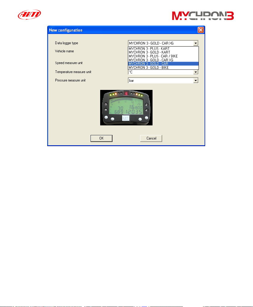
The user will have to set some parameters, listed here above:
• Data logger type: choose among MyChron 3 Plus/Gold/Gold XG and
Kart/Car/Bike. It is reminded NOT to select the KART version;
• Vehicle name;
• Speed unit of measure: choose between km/h and Mph;
• Temperature unit of measure: choose between °C and °F;
• Pressure unit of measure: choose between Bar and PSI.
Once filled all the boxes of the previous screenshot, click on the OK pushbutton to
save the settings. On your PC’s monitor it will appear the Logger manager main
window:
58
Page 59

Here above you can see a short description of all the pushbuttons that can be
used to configure your MyChron 3 Plus/Gold/Gold XG:
• General: with this pushbutton you activate the Logger manager main
window;
• Configuration: this pushbutton will open a very useful dialog box, where
the user is allowed to set the temperature and pressure alarm values,
the RPM shift light threshold values, the RPM and speed parameters
and the measure units;
• Channels: by using this option you may visualize the sensors installed
on your vehicle;
• Customize sensor: this pushbutton allows the user to customize a
sensor, setting the sensor’s calibration curve;
• Logger identification: this button allows the user to detect the
characteristics of the data logger connected to the PC;
• Transmit: once configured the data logger, the parameters have to be
transmitted to the instrument by clicking this button;
• Receive: if you connect to a PC a data logger of whom you do not know
the configuration, you may detect its configuration, by clicking the
Receive button, and to save it in the configuration’s database;
59
Page 60

• Online: the Online button allows the user to make a data acquisition
simulation, in order to verify if the new configuration is correct and if it
has been correctly transmitted to the data logger;
• Calibrate: this button allows the user to calibrate both the lateral
accelerometer and the gear sensor;
• New / Delete / Clone: these three buttons allows the user to create a
new configuration, to delete an old one or to clone an existing one;
• Import / Export: these 2 functions are used to export the selected
configuration (among the available ones) into a “.cfn” file or to import a
configuration (saved into a “.cfn” file) into the configuration database.
• Exit: this button is used to exit the “Logger manager” menu.
Channels
Clicking on the Channels pushbutton it will appear the following screenshot:
60
Page 61

In the window previously shown, it is possible to set the channels acquired by
your MyChron 3 Plus/Gold/Gold XG.
• Channels labelled as CH_1 ÷ 4 may be used to acquire a temperature or
a pressure input, if you are using a MyChron 3 Plus, or may be used to
sample temperature, pressure, potentiometer or Lambda sond, if you are
using a MyChron 3 Gold/Gold XG. The user may choose the sensor
among a long list of Aim standard sensors or, otherwise, may set a
custom sensor by selecting the “Custom sensor management” (see
Customize sensor paragraph).
• If your MyChron 3 is a Gold version one, you may also install an external
gyroscope (for BIKE installations), labelled as CH_7, which will allow you
to create the circuit map.
• Your MyChron 3 Gold/Gold XG (CAR versions) has an internal lateral g-
sensor, labelled as ACC_1, which will allow you to create the circuit map.
61
Page 62

Customize sensor
By using this function, the user can configure a “custom” sensor, setting the
sensor’s calibration curve. This option is very useful when the sensor (pressure,
temperature or other) installed on the vehicle does not appear in the default
sensors list.
It is reminded that the “Customize sensor” option is intended only for
expert users.
To enter this function, please press button Customize sensor: it will appear the
following screenshot:
62
Page 63

In the window’s left part there are three columns: in the first one it is possible to
insert the instrument’s output voltage (i.e. the abscissa values of the calibration
curve), while in the second one it is possible to insert the temperature/pressure
value corresponding to the previous voltage (i.e. the ordinate values of the
calibration curve). These values will be interpolated using a polynomial. In the
third column it is reported the “Curve Error”, i.e. the difference between the
computed curve and the experimental values.
To set how many experimental values you wish to use to create the calibration
curve, please place a check in the column besides the abscissa values.
In the window’s middle part it is reported both the sensor’s calibration curve and
the 5 coefficients (from a
to a4) of the interpolation polynomial. Please, use
0
button “Compute Curve” to refresh the calibration curve to apply any changes.
On the right of the calibration curve there are some boxes, where you can insert
the sensor name, the desired measure units and the sensor type (Temperature,
Pressure or Other).
Below these boxes there are some pushbuttons which allow the user to save or
delete a customized sensor.
In the window’s upper right corner you can see some default “custom” sensors. If
you wish to load one, please click twice on the sensor’s name.
Once correctly defined the new sensor, the user may exit Customization sensor
mode, by clicking on the OK pushbutton, and has to set the new sensor on the
desired channel (press button Channels and follow the instructions reported in the
channels paragraph).
63
Page 64
Channels configuration
Your MyChron 3 Plus/Gold/Gold XG is equipped with 14 fully configurable
coloured led; the 4 ones placed on the left and right of the display unit represent
the 4 analog inputs (temperatures and pressures) maximum alarms, while the
other 10 led in the upper part of the display are called Shift light.
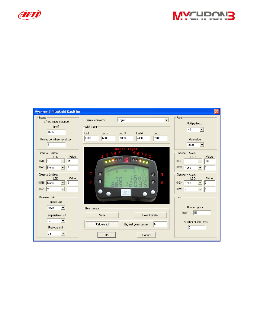
By clicking on the Configuration icon it will appear the following screenshot:
• Wheel circumference: this function allows the user to set wheel
circumference (in mm or in inches); this value is fundamental to correlate
the wheel revolution speed and the vehicle speed.
64
Page 65

• Number of pulses per wheel revolution: this function allows the user to
set the number of pulses per wheel revolution (i.e. the phonic wheel
teeth number), in order to measure the wheel revolution speed. When
the sensor passes by a gear tooth, it generates an electric pulse if the
phonic wheel is made up of just one tooth, the instrument will measure
one impulse per lap, while, if it is made up of more than one tooth, the
number of pulses per lap will be greater than one.
• Configuring the Shift light led: in the window’s middle part it is possible to
set 5 RPM values, each one corresponding to a coloured led. The five led
progressively turn on in order to indicate the pilot to shift gear.
To set the proper RPM value, you have to modify the values in the
different boxes.
The 10 led are so coloured: the first two on the left and the first two on the
right are green coloured, the middle ones are orange coloured and the
last four are red. When the engine reaches the RPM value set in the 5
box, all the five led start blinking, informing the pilot to change gear.
th
If a value is set to 0, the corresponding led will be disabled.
• Number of pulses per engine revolution: this option represents the
number of pulses, acquired from the coil or from the ECU, per engine
revolution. The user may choose the multiply factor among these values:
/1, /2, /3, /4, /6 and *2. For instance, the correct value for a 4 strokes 4
cylinders engine is /2.
• Maximum RPM value: this option allows the user to set the Maximum
RPM value acquired by the instrument.
65
Page 66

• Configuring the 4 alarms led: the 4 alarms led may be configured as
Maximum alarms, Minimum alarms or both for the 4 analog inputs. This
means that led #1, for instance, may switch on when temperature 1
reaches a value greater and/or lower than a fixed value. It is reminded to
select the led number inside the “High led” menu if you wish to set a
Maximum alarm (max value 1999), otherwise, if you wish to set a
Minimum alarm (min value -99), select the led number inside the “Low
led” menu. If you do not wish to set an alarm, please choose the “None”
option.
• Configuring the unit of measure: the user can set the Speed (Km/h or
Mph), Temperature (°C or °F) and Pressure (Bar or PSI) unit of measure
• Gear sensor: the software allows you setting the gear sensor type.
Select “None” if you do not wish to see the gear number, select
“Potentiometer” if your vehicle is equipped with a gear sensor installed
inside the gearbox or select “Calculated” if you wish to use a software
algorithm to calculate the engaged gear. In this case, the “Higher gear
number” box will become enabled: please insert the gear number.
• Configuring the lap parameters: by setting these two parameters, the
user will be able to acquire the correct lap time and, if more than one
optic transmitter is available, the split times. For further information on
these parameters, please refer to the “Beacon obscuring time and split’s
number” paragraph reported in the “Configuration functions” paragraph.
• Language selection: the user may choose the display text language
among 6 different languages: Italian, English, German, Spanish, French
and Slovenian.
66
Page 67
Transmitting the configuration
It is recommended, before transmitting the configuration, to switch on the
instrument and to connect it to the PC’s USB port.
Once set all the parameters, it is necessary to transmit the configuration to the
instrument.
In order to transmit the configuration, you have to press the Transmit pushbutton
and the system, automatically, will download the configuration from the PC to the
instrument’s Flash memory.
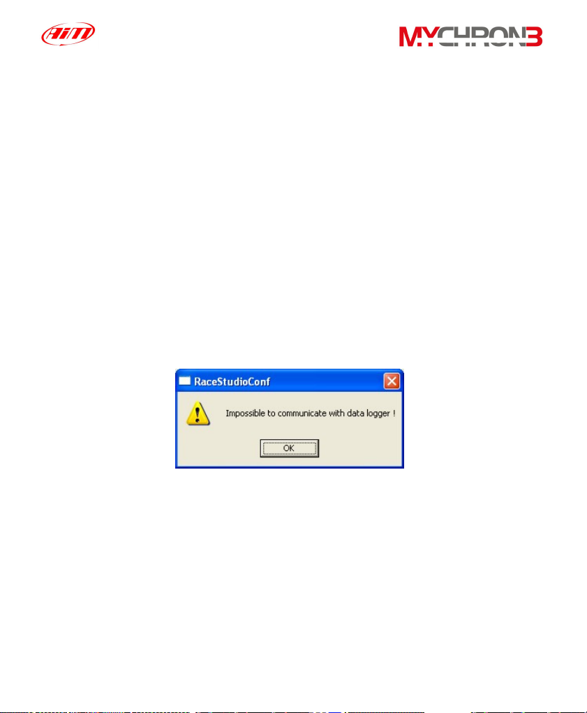
If the data logger is not correctly connected to the PC’s USB port or if the data
logger is switched off when transmitting the configuration, it will appear the
following screenshot on your PC’s monitor:
Please, ensure that the data logger is switched on and correctly connected to the
PC and then retry to transmit the configuration.
Sensors calibration (Gold/Gold XG versions only)
Once the configuration has been transmitted to the instrument, it is absolutely
necessary to autocalibrate the internal lateral g-sensor (or the Gyroscope) and
the “potentiometer distance”, and to calibrate the “mid zero potentiometer”, the
67
Page 68

“zero based potentiometer” and the gear sensor (for the gear sensor, please refer
to paragraph “Gear sensor calibration”).
In order to calibrate/autocalibrate, press button “Calibrate”: the following
screenshot will be prompted:
• The g-force sensor, the gyroscope and the “potentiometer distance” need
to be autocalibrated pressing button “Click here to autocalibrate all
sensors in the list”. Once autocalibrated, the “calibration status” will turn
from “To calibrate” in “Calibrated”.
In order to correctly autocalibrate the g-sensors (accelerometer and
gyroscope), it is suggested to keep the car as horizontal as possible and
to leave the bike on the prop-stand.
68
Page 69

• The “mid zero potentiometer”, the “zero based potentiometer” and the
gear sensor need to be calibrated. Press the button “Calibrate”
corresponding to the channel you wish to calibrate and follow the
instructions prompted on your PC’s monitor.
Once all the sensors have been calibrated, it is absolutely necessary to transmit
the calibration to the logger pressing button “Transmit calibration”.
It is reminded that the calibration/autocalibration procedure is fundamental
to acquire correct data.
Gear sensor calibration
To calibrate the gear sensor, once entered calibration mode by clicking the
“calibrate” button, to select the “Gear sensor calibration” button. It will appear the
following screenshot:
69
Page 70

Now, please follow the instructions listed here above:
• Check the box corresponding to the gearbox’s gear number;
• Engage the neutral gear;
• Press the “Continue” button;
• Engage the first gear;
• Press the “Continue” button;
• Repeat this procedure until the last gear has been engaged (the
instrument supports gearboxes up to 9 gears);
• Once the last gear has been engaged, press the “End Calibration” button;
• Once the gear calibration has finished, it is absolutely necessary to
transmit the calibration to your MyChron 3 Plus/Gold/Gold XG by
pressing the “Transmit calibration” button.
Online visualization
Once you finished calibrating/autocalibrating the sensors, it is suggested to enter
the “Online” mode, by pressing the Online button in the “Logger manager” main
window, in order to verify that each channel has been correctly configured.
The “Online” visualization mode will allow you to control if the
temperature/pressure sensors have been correctly set and if the gear sensor and
the accelerometers have been correctly calibrated. It is also possible to see the
“Battery charge level” and to start a test data acquisition, in order to verify that the
system is correctly working.
70
Page 71

Attention: if the gear channel and the accelerometer one have not been
correctly calibrated, it will not be possible both to acquire the current gear
and, for MyChron 3 Gold/Gold XG only, to create the circuit map. It is
recommended to pay a particular attention when calibrating/autocalibrating
the channels.
71
Page 72

How to download a test
Once a test session has finished, it is possible to download the data stored in the
instrument’s memory.
In order to correctly download these data, please connect your MyChron 3
Plus/Gold/Gold XG to the PC’s USB port by using the USB cable and to switch
on the instrument.
Downloading a test
To download the data, please run Race Studio 2 and, then, click on the
“Download” button, located in the commands toolbar: the file download will
automatically start and it will appear the following screenshot:
72
Page 73

• In the window’s upper part you can see a “wait-bar” which informs you on
the download percentage status;
• In the line directly below the download wait-bar, there is a function which
allows the user to Clear the logger memory after saving data or to leave
data in the instrument’s memory: if you wish to clear the memory after
saving data, please place a check in the proper cell;
• Once downloaded the instrument’s memory, the Save button, located on
the right of the window, will become enabled. If the user presses this
button without specifying the file name and the download folder, the file
will be automatically saved in the default folder “X:\Program
files\AIM\DATA” (where X represents the hard drive where you have
installed Race Studio 2) with the default name “new.drk”.
• If you wish to save the file with another name, please insert the file name
in the “Name” box. Moreover, if you wish to save the file in custom folder,
please press button “Browse”: you will be allowed to choose the desired
folder, as showed in the following image.
73
Page 74

• If you have not placed a check besides the “Clear logger memory after
saving data” option, once you press button OK to exit download window,
it will appear a dialog box where the user is allowed to choose whether to
clear the or not to clear the logger memory. Please, select the desired
option and exit download.
Inserting the test in a database
Race Studio 2 has a new and innovative tests storing system based on
databases.
This storing system allows the user to save the files specifying 5 characteristics,
such as the vehicle name, the driver, the track, the championship and the test
type. Such information are saved together with the test file and are very useful, as
they allow the user to group the files into self-defined categories, each one
characterized by 5 attributes (vehicle, driver, track, championship and test type).
• When saving a new test file, it will be possible to insert this file in the
previously set database categories or to create a new category.
• When loading a test from database, the user may select the desired
category from the database and all the tests which do not belong to that
category will not be shown (in this case, the database works like a filter).
74
Page 75
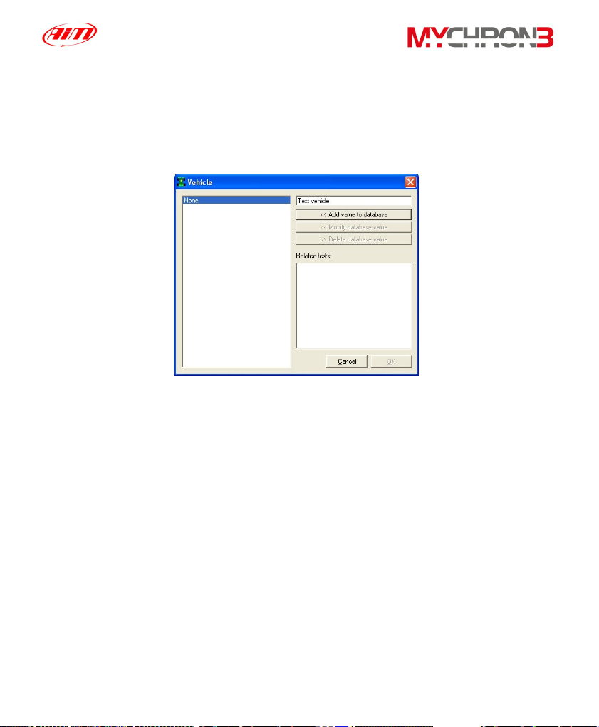
To insert a test in the database, please follow these instructions:
• Once the download has finished, please enter the file name;
• Then click on the “Add/Modify” button corresponding to the Vehicle
attribute. It will appear the following window;
• If the database is empty or you wish to create a new category, please fill
the upper right box with the new Vehicle category and then click the “Add
value to database” button. The new category will appear in the left column
and the “OK” button will become enabled. Then click the “OK” button;
• If the desired category appears in the previously set database categories
(left column), you may select it by single-clicking on the name. Then click
the “OK” button;
• It is reminded that, if you do not wish to specify any category, the file will
be saved in the database and the attributes will be set to “None”.
• Please, repeat this procedure until the 5 categories have been filled.
Once all the attributes have been set, like in the following image, please
click the “OK” button.
75
Page 76

76
Page 77

How to use Race Studio Analysis
Race Studio Analysis is software properly developed to analyse the data
acquired with your gauge. The map creation option (available with MyChron 3
Gold/Gold XG versions only), the possibility to compare different laps, the data
animation option, the possibility to plot channels VS time, VS distance or VS
frequency, the histograms plotting option and the very useful math channels,
make Race Studio Analysis a very powerful instrument to analyse and improve
the driver performances.
It is reminded that all the “.drk” files, downloaded with the previous software Race
Studio 1, are perfectly compatible with the new one.
If you wish to update Race Studio Analysis, together with Race Studio 2,
please connect to our website www.aim-sportline.com
and go to “Download”
page, where it is possible to download the latest updates. To install the update,
click twice on the downloaded file and follow the instructions you see on your
PC’s monitor.
To run Race Studio Analysis, please click twice
on the corresponding icon (reported here above)
that you can find on your PC’s desktop.
It is also possible to run Race Studio Analysis
while working with Race Studio 2 clicking on the
“Analysis” tab, using the “F5” function key
or clicking the following shortcut “Start \ Program \ AIM \ Race Studio 2 \ Race
Studio 2 Analysis”.”
77
Page 78

Once run Race Studio Analysis, it will appear the following window:
The “Test database and lap manager” window is organized on different layers and
allows the user to load/unload a test and to manage both with the database and
the loaded tests.
How to load a test
There are two possible ways to load a test: the first one (recommended) is based
on 5 selection criteria (ensure that the “Use selection criteria” box is checked),
while the second one does not use these criteria.
Open test from database using the selection criteria
: Race Studio 2 and Race
Studio Analysis have been designed to manage the test files using a database.
In the “Test database and Lap manager” window you can see, in the lower part,
all the tests included inside the database and, in the upper part, the database
78
Page 79

categories and sub-categories. To select a test from the database using the
selection criteria, please left-click on the desired selection pushbutton (i.e. “Select
track”, “Select vehicle”, etc…): it will appear the corresponding selection window.
For instance, here below on the left it is shown the “Test type selection”,
corresponding to the “Select test type” pushbutton.
In order to choose a database’s sub-category, place a check besides the desired
one, as shown in the second “Test type selection” window’s screenshot.
It is reminded that you may select more than one sub-category at the same time:
for instance you may select both “Generic testing” and “Qualifying testing”.
It is recommended to repeat this procedure for all the 5 database’s categories
(track, vehicle, driver, championship and test type).
All the tests which do not belong to the selected sub-categories will be filtered and
will not be shown in the “Test database and Lap manager” window’s lower part.
To load a file, once the desired database’s categories have been checked, you
may double-click on the file, you may select it and then press button “Open test”
or you may right-click on the file name and choose the “Open test” function.
79
Page 80

Open test from database NOT using the selection criteria: if you do not wish to
use the selection criteria, it is suggested to remove the check besides the “Use
selection criteria” checkbox.
To load a file, you may double-click on the file, you may select it and then press
button “Open test” or you may right-click on the file name and choose the “Open
test” function.
The “Test database and Lap manager” window also allows the user to insert a
new test inside the database (please refer to the “Inserting the test in a database”
paragraph), to delete a previously saved test from the database and to modify the
test properties. Once a test has been loaded, it will appear the window shown
here below, where you can find both the “Test database” layer and the “Loaded
tests” layers.
80
Page 81

It is reminded that you may load up to 4 different tests (i.e. files) at the same time
(as shown in the previous screenshot), in order to make comparisons between
many different laps.
If you wish to select a particular lap, you may double-click on the corresponding
lap number or you may single-click and choose the “Show lap” function: when the
lap is selected, the green icon located on the left of the lap number turns yellow
coloured. To unselect a lap, click twice on the lap number.
How to plot a channel
Race Studio Analysis will allow you the ability to plot the recorded laps and the
sampled channels versus time, distance and frequency.
For instance, if you wish to plot engine’s RPM and the vehicle speed versus time,
first of all you have to select these measures by clicking on them in the “Measures
and laps” toolbar, located on the left of Race Studio Analysis window, and then
you have to click on the “Plot vs. time” icon.
In order to plot a channel vs. time, it is also possible to use the shortcut
“CTRL+F1” or to click “View \ Plot vs. time” command.
In the following graph, on the left, it is shown the speed (black) and the RPM
(orange) diagram during a lap, while, on the right, it is shown the “Measures and
laps” toolbar.
Left click on the desired channel name (inside the “Measures and laps” toolbar) in
order to add a sampled channel to the graph.
81
Page 82

Left click on the coloured-boxes column if you wish to change the graph colour:
the user may set the desired colour for each recorded lap and for each sampled
channel. If you wish to add the scale to the graph, left click in the checkbox
corresponding to the desired channel name.
Left click on the pushbuttons of the last column of the “Measures and laps”
toolbar to load the “Measure information” dialog box: this window allows the user
to change the channel name, the plotting scale and the unit of measure.
It is also possible to amplify and shift the diagram by using the
“Value=(Value*A)+B” option: A is the amplification factor (included between -1000
and +1000), while B is the shift factor (included between –500000 and +500000).
In the following picture it is reported the “Measure information” dialog box.
82
Page 83

If you choose a channel from the channel list in the right upper corner list, it will
also appear the parameters (in the lower left corner) that the user can set (i.e.
RPM multiply factor, wheel circumference, pulses per revolution, etc…)
How to create your track map (Gold/Gold XG versions only)
The internal lateral g sensor or the external gyroscope allow you the ability to
create a circuit map on your PC.
To create a circuit map, once loaded a test and selected a good lap
(labelled as “Lap marker” in the Lap cause column of the Lap manager
dialog box) please press “Map \ New” from the Command toolbar or
“Shift+F4” keys: it will appear the following screenshot:
83
Page 84

The user will be able to modify a large number of parameters by pressing the
different pushbuttons, whose working is here above explained:
1. Track shape cursor: this button allows the user to modify the curves’
radius of curvature, obtaining more or less open shaped curves.
2. Track type: it is possible to choose the track type between 4 choices:
Clockwise, Counter Clockwise, Figure-8 and Open Shaped. Most of
circuits belong to the first two types, while, for instance, the circuit of
Suzuka (Japan) is a Figure-8 track type.
3. Two Wheels / Four Wheels: this option has to be set to “Four Wheels” if
using a car or to “Two Wheels” if using a bike.
4. Default values: this pushbutton loads the default values for the different
parameters that can be set during the map creation.
84
Page 85

5. File name: once the map has been correctly created, it is possible to save
it by choosing its “file name” and clicking the OK pushbutton.
6. Rotation pushbuttons: by using these buttons it is possible to right
(Clockwise) or left (Counter Clockwise) rotate the circuit map of a 5 or 30
degrees angle.
7. Modify parts pushbuttons: these four buttons will allow the user to modify
the track map just created. In particular it is possible to
a. Divide a split in two separate splits;
b. Remove an intermediate split;
c. Change a circuit part from Straight (green line) to Corner (blue /
red lines) or vice versa. It is reminded that it is not possible to
have two consecutive straights but each straight has to be kept
separate from another one by one curve at least.
d. Mirror the track map.
Once the map has been created and saved, it is possible to recall it from the “Map
Manager” dialog box (shortcut “SHIFT+F2”) by double clicking on the desired one.
85
Page 86

Track map creation troubleshooting
In this paragraph it will be described the possible solutions to the mostly common
map creation troubles encountered.
1. If it appears the following window
please select a “Good lap, labelled as “Lap marker” in the Lap cause
column of the Lap manager dialog box, and deselect the previously used
lap (by double clicking on the lap number).
2. Select a lap without many skids.
3. Verify that it is set the correct vehicle type (2 or 4 wheels) in the “Modify
track map” window.
4. Verify that the values stored in both speed channel and lateral
acceleration one are sensible: lateral acceleration has to be near to 0 in
the straight line, while speed must be greater than 0 and must not have
high or low peaks.
5. If lateral acceleration, or the gyroscope signal, in the straight line is not
quite near to 0, it is probable that the lateral accelerometer, or gyroscope,
has not been autocalibrated. It is possible to solve this problem by
summing or subtracting a fixed value (see “Measure Information” dialog
box) in order to have 0 in the straight line. Please, before starting a new
test run, remember to calibrate the internal lateral accelerometer.
86
Page 87

MyChron 3 Plus/Gold/Gold XG quick reference guide
Configuration via keyboard
• Press MENU/<< to activate the configuration mode.
• Press MENU/<< (previous option) or >> (next option) to scroll through
the configuration menu.
Setting the number of splits
• Select the “Number of Splits” option.
• Press MEM/OK to enter edit mode.
• Press MENU/<< or >> to set the number of splits.
• Press MEM/OK to save or VIEW to quit.
Setting the obscuring time
• Select the “Obscuring Time” option.
• Press MEM/OK to enter edit mode.
• Press MENU/<< to set the correct number of seconds.
• Press >> to switch between digits.
• Press MEM/OK to save or VIEW to quit.
Gear calibration
• Select the “Gear calibration” option.
• If you have selected the “Gear with sensor” option, follow these
instructions:
o Engage the NEUTRAL gear.
o Press >> pushbutton.
o Engage the first gear.
87
Page 88

o Press >> and repeat this procedure for all the gears.
o Once the last gear has been engaged, press button
MEM/OK.
o To restart calibration procedure, press button MENU/<<.
• If you have selected the “Gear computed” option follow this
procedure:
o Start for some “Learning laps”.
o During these laps, engage all gears.
o Stop the vehicle and turn off the engine in order to let the
gear calculation procedure start.
o If the calculated gears do not correspond to the engaged
ones, run another “learning lap”.
Setting the temperature alarms
• Select the “MAX/MIN TE1/TE2 Alarm” option.
• Press MEM/OK to enter edit mode.
• Press MENU/<< until the correct number appears.
• Press >> to switch between digits.
• Press MEM/OK to save or VIEW to quit.
Shift lights configuration
• Select the “Shift light” option.
• Press MEM/OK to enter edit mode.
• Press MENU/<< until the correct number appears.
• Press >> to switch between digits.
• Press MEM/OK to save and to configure the next led.
• Press VIEW to quit.
88
Page 89

Setting the circumference wheel
• Select the “Wheel circumference” option.
• Press MEM/OK to enter edit mode.
• Press MENU/<< until the correct number appears.
• Press >> to switch between digits.
• Press MEM/OK to save or VIEW to quit.
Setting the pulses per wheel revolution
• Select the “Pulses on wheel” option.
• Press MEM/OK to enter edit mode.
• Press MENU/<< until the correct number appears.
• Press >> to switch between digits.
• Press MEM/OK to save or VIEW to quit.
Setting the maximum RPM value
• Select the “Max RPM value” option.
• Press MEM/OK to enter edit mode.
• Press MENU/<< or >> to select the desired RPM value.
• Press MEM/OK to save or VIEW to quit.
Setting the RPM factor
• Select the “Spark for revs” option.
• Press MEM/OK to enter edit mode.
• Press MENU/<< or >> to select the desired value.
• Press MEM/OK to save or VIEW to quit.
89
Page 90

How to use MyChron 3 Plus/Gold/Gold XG
Viewing data per best lap time
• Press MEM/OK to see the best lap and the maximum RPM and
temperatures values.
• Press MEM/OK to see minimum RPM and temperatures values.
• Press VIEW to switch from RPM to speed.
• Press VIEW twice to return to main display mode.
Viewing other completed lap data
• Press MEM/OK.
• Press MENU/<< to view a previous lap or >> to view a following lap.
• Press VIEW to return to main display mode.
Configuration via software
• Install Race Studio 2 software (see “Software installation” paragraph).
• Connect the instrument to a “switched on” PC by using the USB cable.
• Switch on your MyChron 3 Plus/Gold/Gold XG and install the USB
drivers (see “Installing the USB drivers” paragraph).
• Start Race Studio 2.
• Select MyChron 3 Plus/Gold/Gold XG and click “Logger manager”
button.
• Set the correct values in the boxes of the “New configuration” dialog box.
• Click “Channels” button.
90
Page 91

• Set the correct input channels by double-clicking in the “Sensor type”
column.
• Click “Configuration” button and set the following parameters:
• Message language;
• Wheel circumference and pulses per wheel revolution;
• Shift light led;
• RPM multiply factor and RPM maximum value;
• Channels’ alarms;
• Speed, temperature and pressure unit of measure;
• Beacon receiver obscuring time and number of splits;
• Transmit the configuration to the instrument by pressing the “Transmit”
button.
• Calibrate/autocalibrate the sensors (potentiometers, accelerometer,
gyroscope and gear sensor).
• Transmit the calibration to the instrument by using button “Transmit
calibration”.
91
 Loading...