

Page 1
TECHNICAL DOCUMENTATION 10/06/2005 GAUGE
Notes: MyChron 3 Visor technical documentation, dimensions and pinout. Version 1.09
SPEED
BEACON POWER-COM
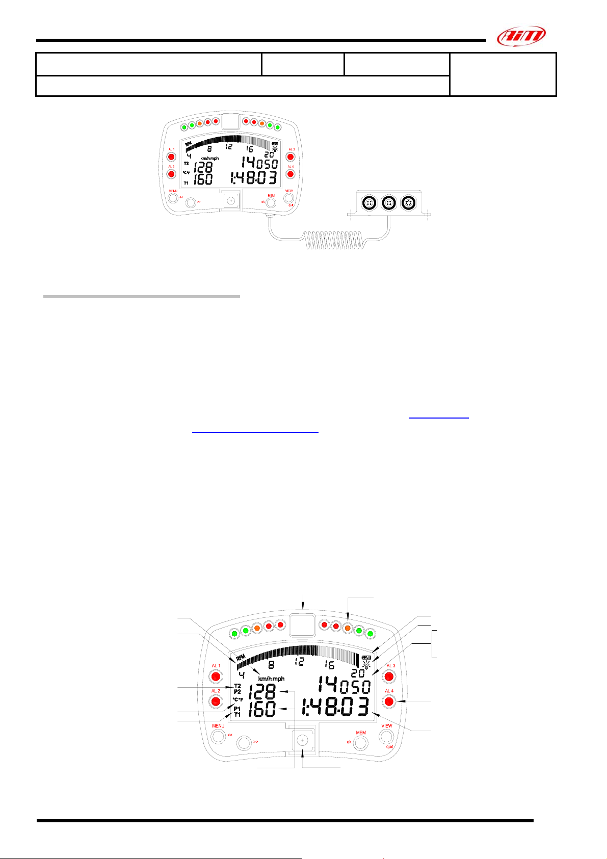
Figure 1: MyChron 3 Visor
Introduction
MyChron 3 Visor represents the new generation of “High-technology” Aim
data acquisition systems for car racing.
MyChron 3 Visor samples and displays speed and lap (split) times.
Moreover it can be interfaced with the engine’s ECU using a Serial / CAN
cable connected to the POWER/COM input to sample all the channels
acquired from the ECU.
To have a complete list of compatibles ECUs, communication protocol and
connection with AIM logger, please refer to “documents” page of our
website www.aim-sportline.com, where You find a dedicated datasheet
called ECU-AIM logger.
The logger records the following parameters:
• lap and split times;
• 1 speed input;
• All the channels acquired from the engine’s ECU.
Data are stored in a the 512 kb internal flash memory and may be
downloaded to a PC through an USB cable. Please, refer to Figure 2 to
get further information concerning the gauge’s display.
Gear display
10 fully configurable shift lights
MyChron 3
VISOR
Speed unit of measure
RPM graphical bar
Configurable RPM scaling
2nd displayed channel
Temperature unit of measure
1st displayed channel
Displayed input channels
USB port
Low battery warning
Night vision
RPM digital value
Speed
Best lap time
Battery voltage
4 alarm led:
from "AL 1" to "AL 4"
Lap / Split times
Figure 2: MyChron 3 Visor display
Technical documentation: MyChron 3 Visor Version 1.09
1
Page 2
Installation notes
• We recommend You to choose a place where both display unit and
“Junction box” are not in contact with oil or fuel; make sure that the
gauge is not installed too close to heat sources and protect the
instrument from vibrations.
• We remind you that your MyChron 3 Visor is not equipped with
internal batteries, so it needs to be powered by an external power
source (i.e. the car’s battery).
• Once the gauge has been correctly installed, you may plug the
speed sensor and the beacon receiver inside the female connectors
located on the Junction box’s front panel. Moreover, you may
connect the gauge to the engine’s ECU using a serial/CAN cable.
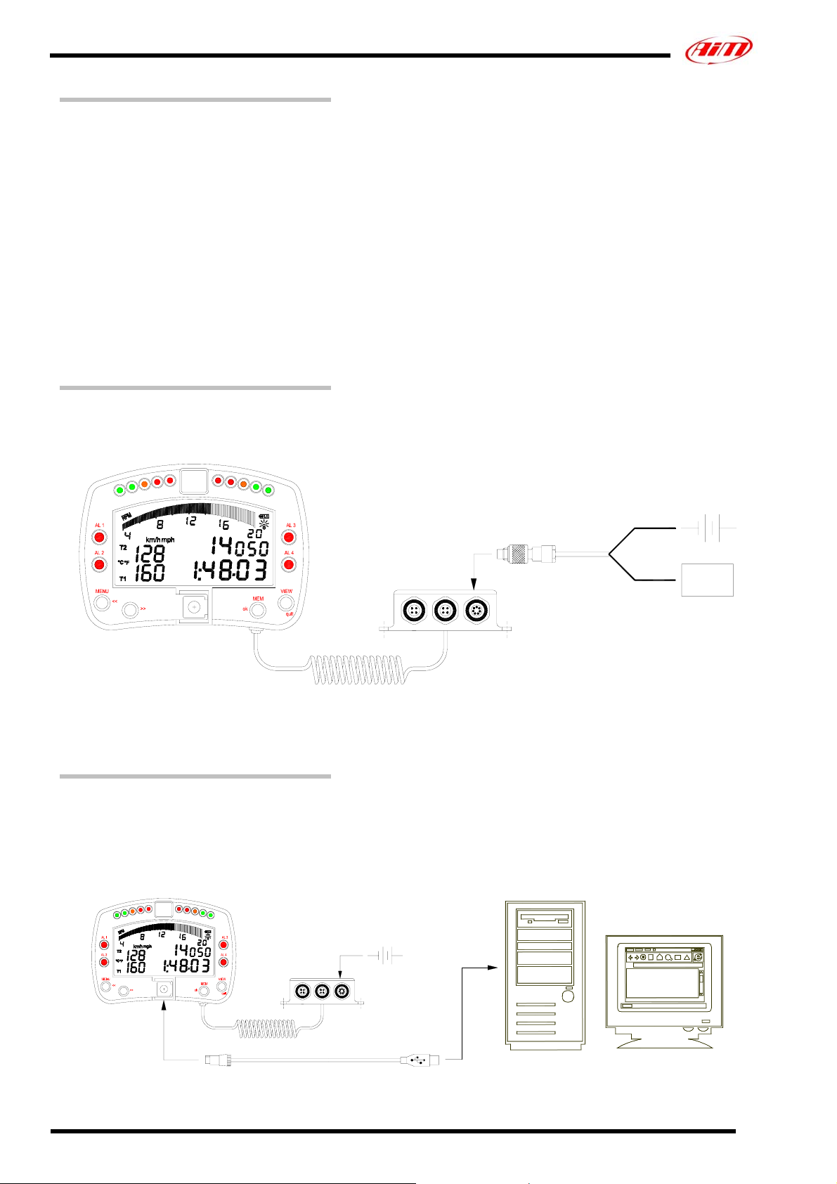
How to connect MyChron 3 VISOR to the ECU
To connect MyChron 3 Visor to the ECU, please use a serial/CAN cable
connected to the gauge’s POWER/COM connector, as shown in Figure 4.
SPEED
BEACON
Figure 4: How to connect your MyChron 3 Visor to the engine’s ECU
How to connect MyChron 3 Visor to the PC
In order to connect your MyChron 3 Visor to the PC, please use the USB
data download cable and plug it both in the gauge’s USB port and in the
PC’s USB port, as explained in Figure 5. Please remember to use a 9-15
Volts external power source in order to be able to switch the gauge on.
9 – 15 VDC
POWER-COM
ENGINE'S
ECU
SPEED
POWER-COMBEACON
Figure 5: How to connect your MyChron 3 Visor to the PC
Technical documentation: MyChron 3 Visor Version 1.09
2
Page 3

Software
Once the data logger has been installed and the sensors plugged in it, the data logger
needs to be configured acquire consistent and correct information.
For a correct configuration, please use Race Studio 2, the software properly developed by
Aim to configure its instruments and analyze stored data and follow the instructions
explained here below.
In Race Studio 2 main window, shown here
below, You can choose your data logger.
Please, select “M3 Log/Visor” and then press
“System manager” button.
Now, please follow these configuration steps:
1. Set the desired input channels;
2. Configure the input channels;
3. Transmit the configuration to the logger;
2) How to configure the gauge
Once checked the input channels, press
“Configuration” button to set the displayed
channels, the alarms etc… The following
screenshot will appear.
1) How to set the input channels
Press “Channels” button to set the sensors you
have installed on your gauge. The following
screenshot will appear.
This screenshot shows all the input channels
sampled by your MyChron 3 Visor.
To correctly configure your MyChron 3
Visor is necessary to set all the parameters
reported in this dialog box:
• Speed channel, wheel circumference
and pulses per wheel revolution.
• Display language.
• Shift lights.
• Rpm
• Channels and alarms concerning
Display page 2
• Obscuring time and Number of splits
• Gear sensor
• Measure units
• Channels and alarms concerning
Display page 1.
3) How to transmit the configuration
Once you have set the input channels and
configured them, the configuration needs to
be transmitted to the instrument. To do so,
please press OK button to save the
configuration. The program will take You
back to “System Manager” general
screenshot: press “Transmit” button.
Please note that, in order to transmit the
configuration, the gauge must be switched
on and connected to the PC, as shown in
Figure 5.
Technical documentation: MyChron 3 Visor Version 1.09
3
Page 4
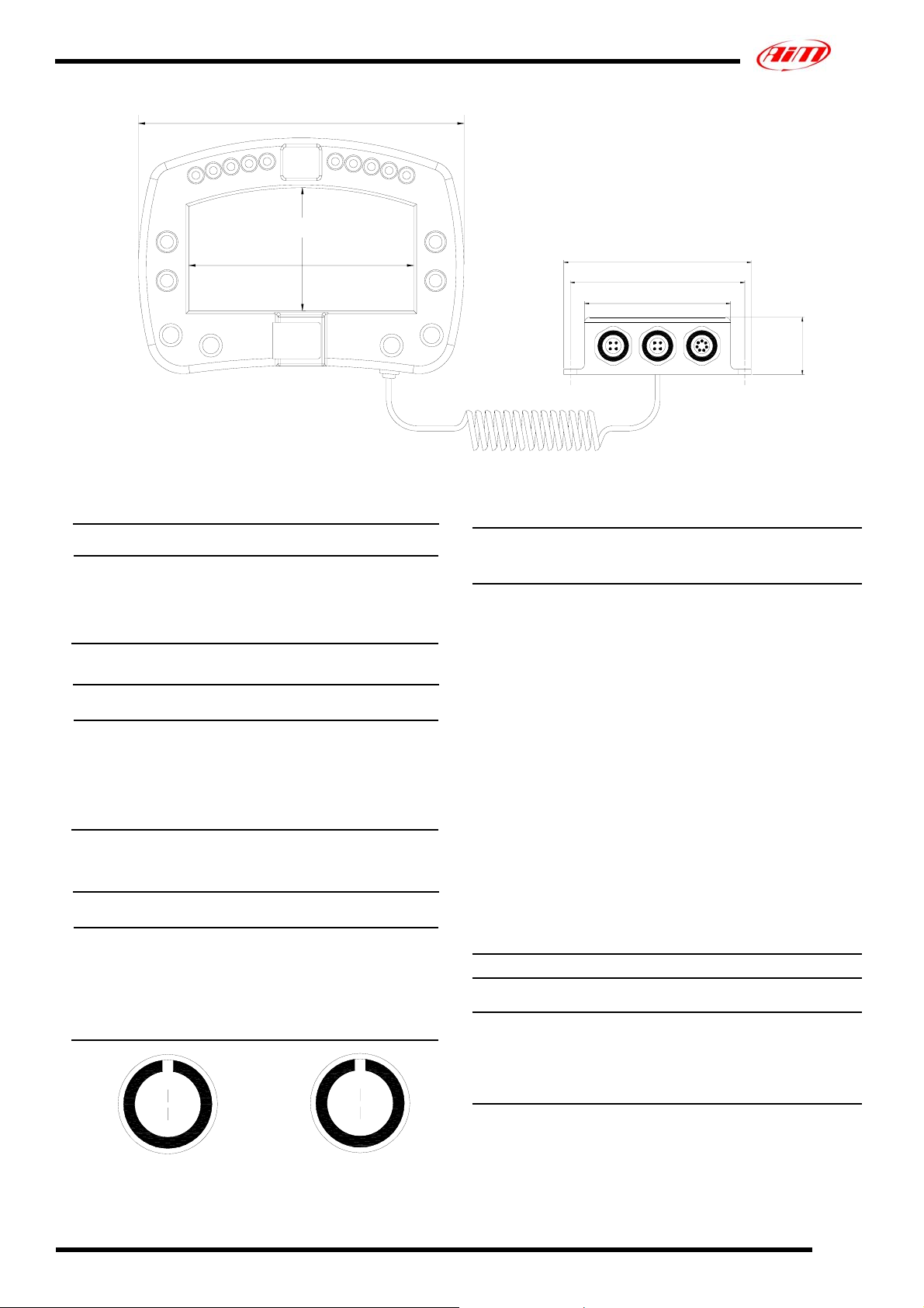
Dimensions
126 [4,96]
48 [1,89]
87 [3,43]
Speed channel pinout
Pin Function Pin Function
1 Speed signal input 3 +V battery
2 GND 4 Not connected
Beacon channel pinout
Pin Function Pin Function
Magnetic / Optic
1
codified lap
2 GND 4
3 +V battery
Optic not
codified lap
POWER / COM channel pinout
Pin Function Pin Function
1 CAN + 5 Rx 232
2 CAN - 6 N.c.
3 + V batt. 9 -15V 7 GND
4 Tx 232
1
4
1
2
3
4 & 7 pins female Binder 712 connectors pinout:
external view
7
6
2
5
3
4
72 [2.83]
64 [2.52]
56 [2.19]
SPEED
BEACON POWER-COM
Dimensions in millimeters [inches]
22 [0.87]
Technical characteristics
General
characteristics
Input channels 1 speed input
Input channels from
ECU
Speed sampling
frequency
External power From 9 to 15 VDC
Internal memory 512 kbytes flash
ECU interface: serial
protocol
ECU interface: CAN
protocol
PC interface 300 kbyte/sec USB
Other characteristics Value
M3 Visor dimensions 126x92x24 mm
Display dimensions 87x48 mm
Environmental IP 65
Value
Max. 64
10 Hz
EPROM
19.2 bps (Pectel and
MBE)
9.6 bps (DTA)
1 Mbit/sec (EFI
EUROPE)
500 kbit/sec (SEAT)
port
Technical documentation: MyChron 3 Visor Version 1.09
4
 Loading...