

Page 1
Made in Italy
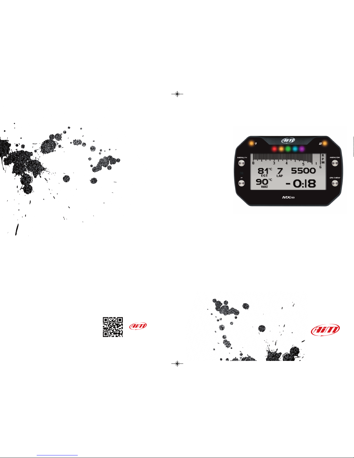
MXm
USER GUIDE 1.00
www.aim-sportline.com
MANUALE MXm 1.00 2018.qxp_Layout 1 01/08/18 15:08 Pagina 1
Page 2

MXm
1 MXm in a few words
2 What is in the kit?
3 Installation, powering and accessories
4 At power on
5 What you can do via keyboard
5.1 Backlight
5.2 Unit of measure
5.3 WiFi
5.4 Tracks Management
5.4.1 Creating a track with MXm
5.5 Counters
5.6 Date and Time
5.7 Language
5.8 System Info
6 MXm and the PC
6.1 Connection to the PC
6.1.1 WiFi configuration
6.1.2 Configuring MXm as an access point AP
6.1.3 Adding MXm to an existing network
6.1.4 WiFi network settings
6.1.5 The Internet connectivity
6.1.6 Connection issues
6.1.7 Working on Mac
TM
with virtualized Windows
TM
6.1.8 Connected device visualization issues
6.2 Configuration of MXm
04
06
10
11
12
13
14
14
15
16
16
17
18
18
19
19
21
22
25
28
30
30
31
34
34
6.2.1 Channels configuration
6.2.2 ECU Connection and configuration
6.2.3 LCUOne C AN setting
6.2.4 Math channels
6.2.5 Status variables setting
6.2.6 Parameters settings
6.2.7 Shift Lights and Alarms
6.2.8 Power Outputs setting
6.2.9 Display settings
6.2.10 SmartyCam stream setting
6.3 Managing a track on MXm with Race Studio 3
6.4 ECU Driver builder
6.5 The device window
7 On the track
7.1 Track page
7.2 Other pages
8 Data recall
9 Data download
10 Data Analysis
11 New firmware upgrade
12 RPM 69
12.1 RPM from ECU
12.2 RPM via a 550V square wave or coil 150400V
13 Connection with SmartyCam and LCUOne
14 Technical specifications and drawings
35
37
38
39
40
42
43
49
51
53
54
60
61
62
62
62
63
65
66
68
69
69
69
72
74
MANUALE MXm 1.00 2018.qxp_Layout 1 01/08/18 15:08 Pagina 3
Page 3
1. MXm in a few words
04 05
n
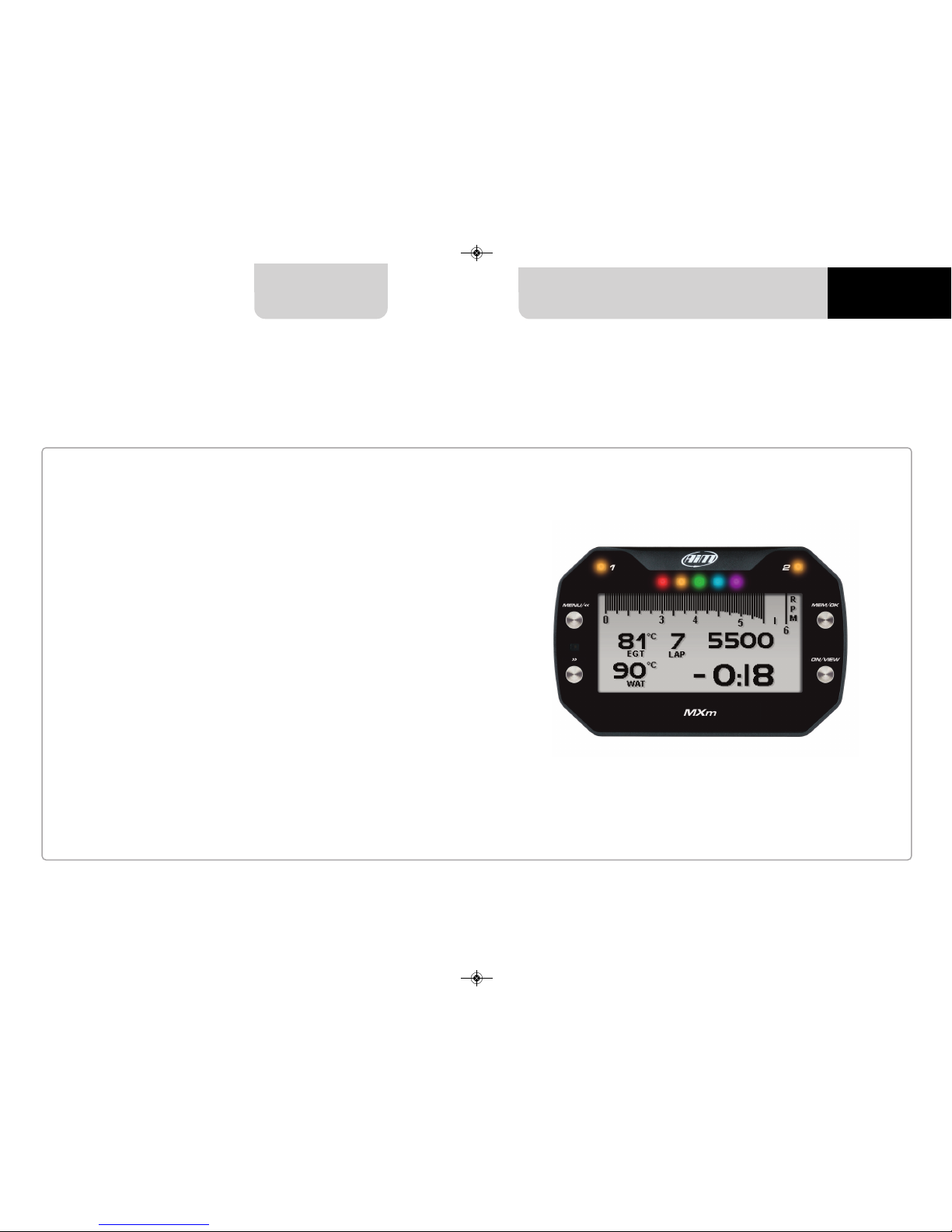
What is MXm?
MXm is the new AiM mini logger that
combines small dimensions, usability
and logging capability.
Why MXm?
Because it features:
n
ECU connection
n
2 speed inputs
n
4 analog inputs
n
2 digital high side output
n
up to 8 configurable display pages
n
integrated GPS + Glonass receiver
n
a huge tracks database to automati-
cally select the track you are racing on
n
a powerful and comfortable Wi-Fi
connection
n
10 RGB LEDs that clearly show if you
are improving or not
n
a huge amount of internal memory
(four gigabytes) capable of recording a
lot of tests
What about ECU connection?
MXm manages all the hardware ECU
connections as well as all the communication lines: CAN, K-Line, RS232. Its
huge database includes more than
1500 protocols you can load in your
MXm.
CHAPTE R 1 MXm
If the vehicle does not have an ECU?
In case your vehicle does not have an
ECU, you can anyway connect MXm to
an RPM wave to synchronize RPM to
the position on the track thanks to the
cable labelled RPM of 37 pins connector harness you find in the kit.
Is MXm an expandable logger?
Yes. MXm can be connected to AiM
LCU-One CAN to maximize your engine
performances and AiM SmartyCam to
see your track performances on your
PC with all the values you need in overlay.
Anything else?
Of course yes.
An app for iPhone is coming! In a few
weeks you will be able to analyse essential data on your iPhone; furthermore, you will be able to see in real
time all the values MXm samples, upgrade its firmware, create new tracks as
well as update your database and modify Wi-Fi settings.
MANUALE MXm 1.00 2018.qxp_Layout 1 01/08/18 15:08 Pagina 5
Page 4

CHAPTE R 2
06 07
MXm
MXm kit includes:
MXm
37 pin connector harness
4 pins connector kit
CD for software installation
2. What is in the kit?
1
2
1
2
3
4
4
3
MANUALE MXm 1.00 2018.qxp_Layout 1 01/08/18 15:08 Pagina 7
Page 5

CHAPTE R 2
08 09
MXm
MXm
37 pins connector
4 pins connector
Nylon body
Integrated GPSRGB Shiftlights Alarm Led 2Alarm Led 1
PushbuttonsWide Graphical display Light sensor
MANUALE MXm 1.00 2018.qxp_Layout 1 01/08/18 15:08 Pagina 9
Page 6
3. Installation, powering and accessories
MXm is powered connecting the 37 pins connection harness you find in the kit to the
vehicle master switch. This way MXm will switch on/off with the vehicle engine.
37 pins connection harness wires to be used are labelled “9-15 VDC” and “GND”.
A said before, AiM MXm features two digital outputs you can turn ON/OFF according
to pre-defined conditions you can set using Race Studio 3 software.
They need the connection of the 4 pins connector included in the kit. Please refer to
MXm pinout you find at the end of this user manual for further information.
CHAPTE R 3 CHAPTE R 4
10 11
MXm
4. At power on
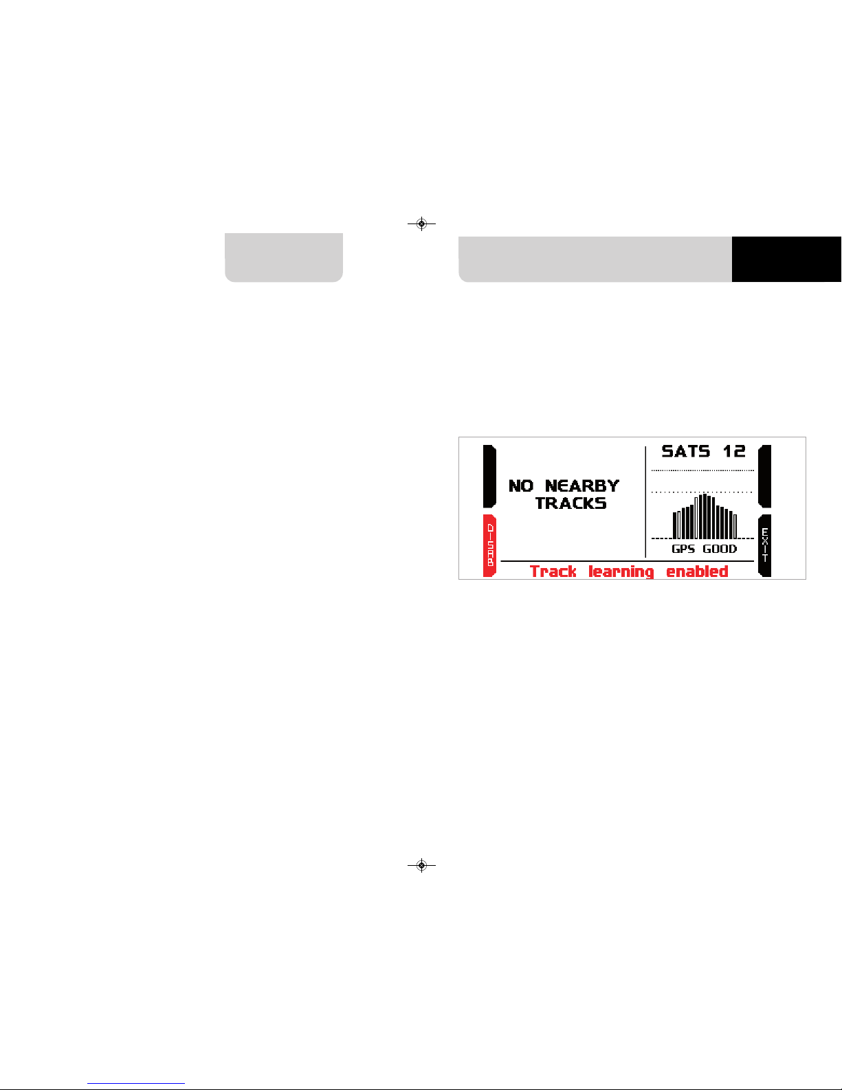
When switched on MXm shows satellite page.
Here you can see the number of connected satellite (SATS 12 in the image above) as
well as the quality of the signal.
If you are on a track not included in MXm database the system shows the message
“NO NEARBY TRACKS and “Track learning” enables automatically. You can disable it
pressing the related button, that switches to “ENABLE” and you only need to press it
again to enable track learning mode. In this second case the system asks for confirmation.
Please refer to “Tracks Management” chapter for further information.
MANUALE MXm 1.00 2018.qxp_Layout 1 01/08/18 15:08 Pagina 11
Page 7
CHAPTE R 5
12 13
MXm
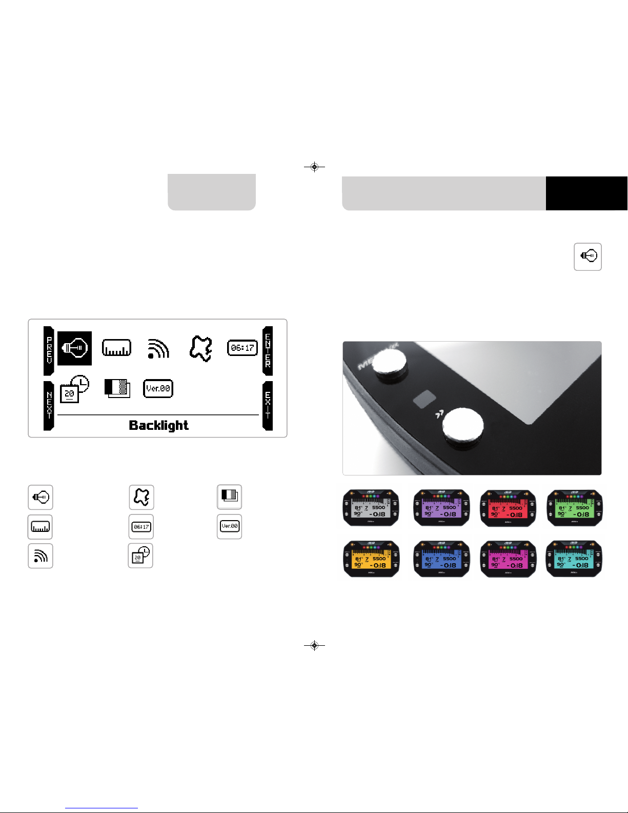
5.1 Backlight
You can set MXm backlight as “AUTO”(Default setting), “ON” or “OFF”.
Thanks to the light sensor, placed left front of MXm, “AUTO” setting switches the
backlight on/off according to the ambient light conditions.
MXm back light can be: white, purple, red, green, yellow blue, magenta and cyan.
5. What you can do via keyboard
MXm is mainly configurable using Race Studio 3 software but some functions are
settable via keyboard as explained here below. Press “MENU” and this page shows
up.
The icons are to manage:
Backlight
Wi-Fi
Date Time
Language
System info
Unit of measure
Counters
Tracks
MANUALE MXm 1.00 2018.qxp_Layout 1 01/08/18 15:08 Pagina 13
Page 8
CHAPTE R 5
14 15
MXm
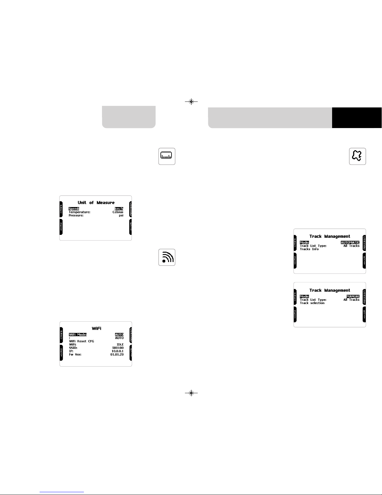
5.4 Tracks Management
MXm built in GPS receiver is used for:
n
Lap time calculation
n
Speed calculation
n
Predictive lap time calculation
n
Position on the track in analysis
To calculate these data the system needs to know the start/finish line coordinates.
MXm comes with a long list of the world main tracks. The list is constantly updated
by our technicians and it updates on your PC when you run Race Studio 3 software
and a connection to the internet is available. Available track selection modes are: automatic and manual
5.3 Wi-Fi
Here you can manage Wi-Fi as well as reset its configuration. Wi-Fi modes are:
n
ON
n
Auto: switches Wi-Fi on when the vehicle is stopped and automatically switches
it off when MXm starts recording, according to the setting you performed in
“Parameters” page of Race Studio 3 software (see paragraph 6.2.6 for further
information)
n
OFF
“Wi-Fi reset CFG” allows you to reset Wi-Fi configuration and is very useful if you do
not remember Wi-Fi password.
5.2 Unit of measure
Here you can manage speed, temperature and pressure unit of measure. Use:
n
“PREV”/”NEXT” buttons to scroll the measure to set
n
“CHANGE” button to change the measure unit
Both track modes provide three track list type:
n
nearest: shows only tracks in a 10 km distance with max 50 tracks shown
n
all tracks: shows all tracks stored in the system in alphabetical order
n
custom: shows only the tracks you have previously created (learning mode)
Automatic:
the system automatically recognizes
the track you are running on, loads
start/finish line and calculates lap
times.
This is the best mode in most cases.
Manual:
allows you to manually select the track
from the internal database.
This mode is to be preferred when multiple track configurations are available
nearby. In this case MXm would anyway recognize the track but would
need at least one complete track lap.
To be ready from the first lap manual
mode would be helpful.
MANUALE MXm 1.00 2018.qxp_Layout 1 01/08/18 15:08 Pagina 15
Page 9
CHAPTE R 5
16 17
MXm
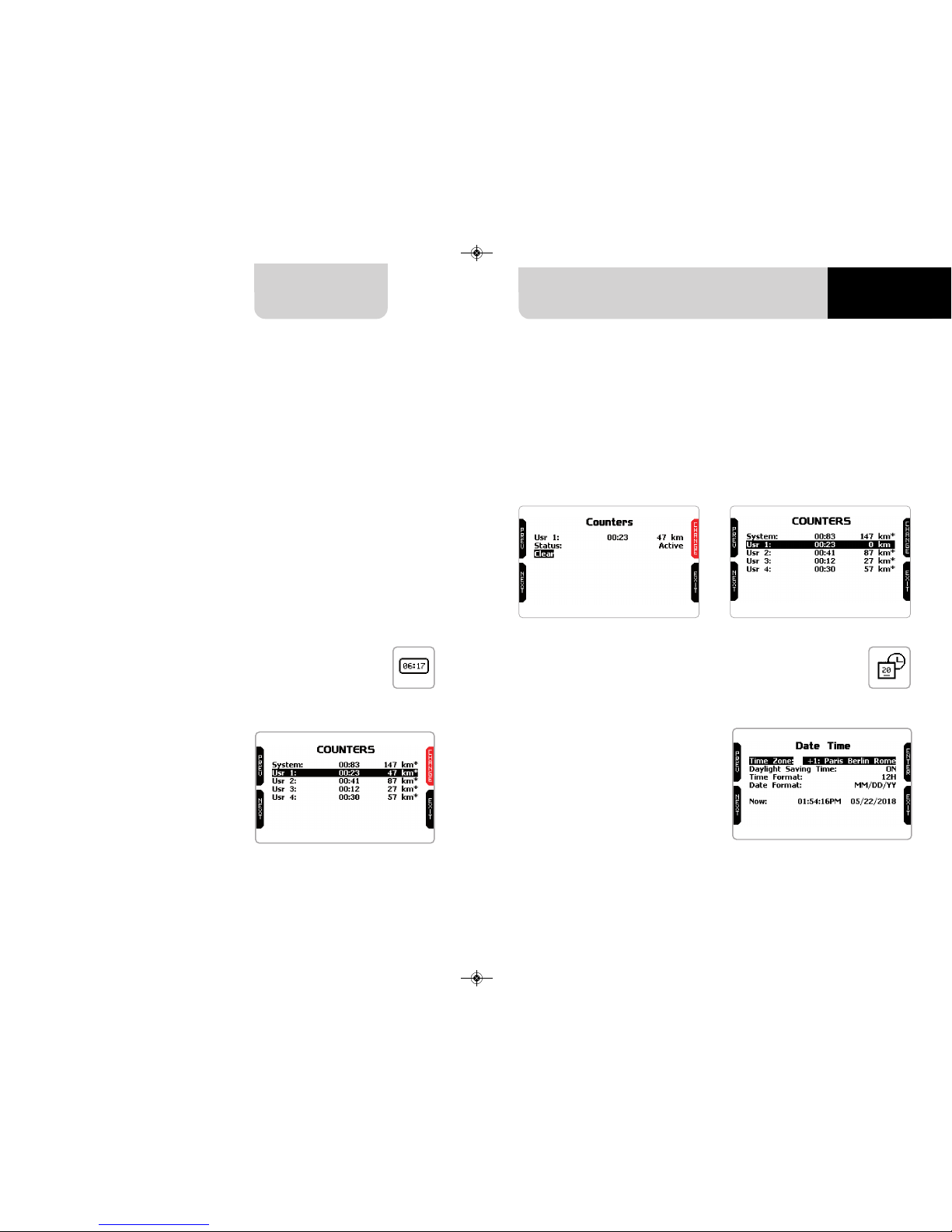
n
scroll to Status and press “CHANGE” to switch from “Active” to “Stop” and vice-versa
n
scroll to clear and press “CHANGE” to reset an odometer (left image below)
n
pressing “EXIT” you come back to odometer page and the odometer you
stopped/reset will not show the asterisk and will show “0” km (in the example
below both operations have been performed on odometer 1 (right image below).
5.4.1 Creating a track with MXm
5.5 Counters 5.6 Date and Time
If you are running in a track NOT included in MXm database the device switches to
“learning” mode and behave this way:
n
it starts sampling all track points
n
when detects that it is crossing the same points for the second time it realizes that
the track is closed and sets a temporary start/finish line showing lap time each
time it crosses that point;
n
at the end of the session the system shows the track map with start/finish line:
you can move start/finish line using MXm side buttons;
n
you can add this new map to MXm database, modify start/finish line coordinates,
name the track and transmit it to the PC at first PC-MXm connection
You find a deeper explanation of track management with Race Studio 3 in the related
chapter and a “Track manager” user manual is available in documentation area, firmware/ software of www.aim-sportline.com.
This page manages the 4 resettable
odometers of MXm.
The system odometer is not resettable.
All odometers are shown on Race Studio 3 too (see chapter about MXm and
the PC).
Each odometer can be activated/deactivated and/or reset. To select the odometer you want to manage press
“CHANGE”.
Here you can set the time zone of your
MXm as well as enable/disable Daylight Saving Time” option. Time zone is
always set manually. Date and time can
be shown in different format.
Time is automatically synchronized as
MXm receives the GPS signal.
MANUALE MXm 1.00 2018.qxp_Layout 1 01/08/18 15:08 Pagina 17
Page 10
CHAPTE R 6
MXm
You can set MXm language. Default setting is English. Press “CHANGE” to set the
language you prefer. At present available languages are (in this order):
n
English
n
Italian
n
German
n
Spanish
n
French
n
Dutch
n
Danish
n
Portuguese
n
Japanese
n
Czech
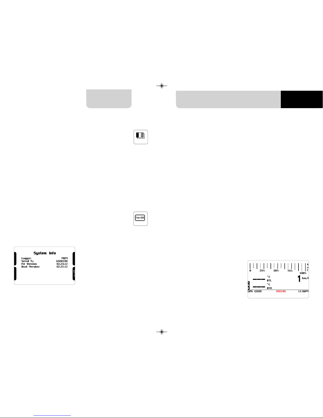
This page shows serial number as well
as firmware and boot version of your
MXm.
n
check that MXm is set on “AUTO”
or on “ON”
n
read your MXm name – mid of MXm
home page bottom line – or look for
it in system information page
Using AiM Race Studio 3 software you can configure MXm, manage its tracks database as well as check other device functions using the device window.
MXm can be connected to the PC via Wi-Fi or via USB.
To connect MXm to the PC via USB use the USB cable you find in the kit: plug it in
the cable labelled “USB” of MXm 37 pins connector harness and in the PC USB port.
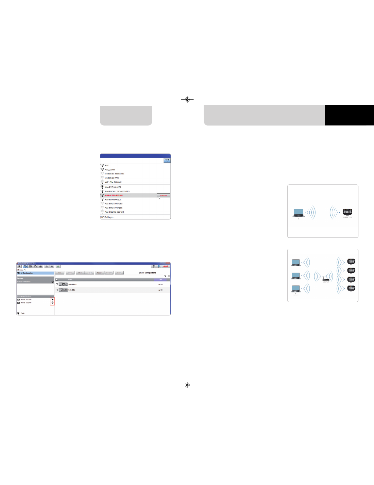
To connect MXm to the PC via Wi-Fi
18 19
CHAPTE R 5
5.7 Language
6 MXm and the PC
5.8 System Info 6.1 Connection to the PC
MANUALE MXm 1.00 2018.qxp_Layout 1 01/08/18 15:08 Pagina 19
Page 11
CHAPTE R 6
20
21
MXm
As far as Wi-Fi connection is concerned
two possible Wi-Fi modes are available.
1 – As an access point (AP – default)
This is the ideal configuration if you
have one only device and one only
computer. In this situation your MXm
creates a Wi-Fi network and works as
an Access Point you can connect your
PC to.
2 – Existing network (to connect to
an existing Wi-Fi network – WLAN)
This mode is complex and implies an
external access point (AP) but it is also
more flexible and powerful because allows you to communicate with more
than one device and with more than
one computer in the same network.
MXm and the PC must connect to an
existing Wi-Fi network made by a device that works as an external access
point.
n
click Race Studio 3 Wi-Fi icon and se-
lect your MXm
n
press “Connect” and wait just a few
moments
Once the system is connected to the PC the software shows it bottom left of the
software home page showing also the way it is connected: an USB icon for USB
connection and a Wi-Fi icon if connected via Wi-Fi as shown here below.
6.1.1 Wi-Fi configuration
When working in WLAN mode MXm has two available security levels:
n
network authentication: network password
n
device authentication: MXm password
Both levels allow you to use different strategies. A PC in WLAN, for example, can see
several AiM devices but can communicate only with those he knows the password
of. If you forget the password you can reset Wi-Fi configuration from MXm menu as
explained before.
MANUALE MXm 1.00 2018.qxp_Layout 1 01/08/18 15:08 Pagina 21
Page 12
CHAPTE R 6
22 23
MXm
n
run Race Studio 3
n
click Wi-Fi icon and select your device
n
in a few seconds the connection is established
To set other parameters create a unique password to protect your device/your network. With a password the communication is safe and encrypted using WPA2-PSK
standard.
Characters allowed in the password are all letters, also capital, all digits and these
characters: ‘+-_()[]{}$£!?^#@*\\\”=~.:;/%"
“Space” type can be used if it is not the first one because this could cause incomprehension in some WindowsTMversions.
This is MXm default configuration and is the easiest and most direct connection
mode, ideal if you want to communicate with one MXm using one PC. It is free and
so completely accessible by anyone. Please set an access password as soon as possible.
To establish a Wi-Fi connection:
n
ensure that the Wi-Fi is enabled
n
read your MXm Name
6.1.2 Configuring MXm as an access point (AP)
MANUALE MXm 1.00 2018.qxp_Layout 1 01/08/18 15:08 Pagina 23
Page 13

CHAPTE R 6
24 25
MXm
This AP or SSID name is unique for your device.
An example of name is:” AiM-MXm-00100” where:
n
“AiM” is the prefix of all AiM devices
n
“MXm” is the device identifier
n
“00100” is your device serial number assigned by the factory.
To make your device more recognizable you can add a name to the SSID. The limit is
of eight characters. Allowed characters are all letters, capital too, all digits and these
characters: ‘+ - _ () [] {}!.
“Space” type can be used provided that it is not the first one because it can cause incomprehension in some WindowsTM versions.
If, for example, you add the driver’s name, Tom Wolf, the network name (SSID) becomes:
”AiM-MXM-00100-TomWolf”
Once all parameters set click “Transmit”. MXm reboots and is configured with the new
parameters. If MXm is protected by a password, as recommended, Race Studio 3 will
ask that password to authenticate.
Please Note the same Wi-Fi connection can be created with the operative system
tool. Once the device has been authenticated in the Wi-Fi network you can
communicate with it using Race Studio 3.
This situation is ideal for a team with multiple drivers and staff members and is desired
to communicate with one or more AiM devices using the same PC network. Each
MXm can have its password that adds another security and privacy level to the network.
Race Studio 3 will show all MXm connected to the same network under “Connected
devices” label, bottom left of the software page: click your device.
Enter “Wi-Fi and properties” tab and set it on “Existing Network”; fill in network name,
network password and device password.
Transmit the network settings to your device clicking “Transmit”: your device reboots
and joins that network.
Please note: the only admitted password are those following WPA2-PSK standard.
6.1.3 Adding MXm to an existing network
MANUALE MXm 1.00 2018.qxp_Layout 1 01/08/18 15:08 Pagina 25
Page 14

CHAPTE R 6
26 27
MXm
To complete this procedure use Race Studio 3 software as here explained. To obtain connectivity on the device the PC has to be authenticated to the same
network as shown here below.
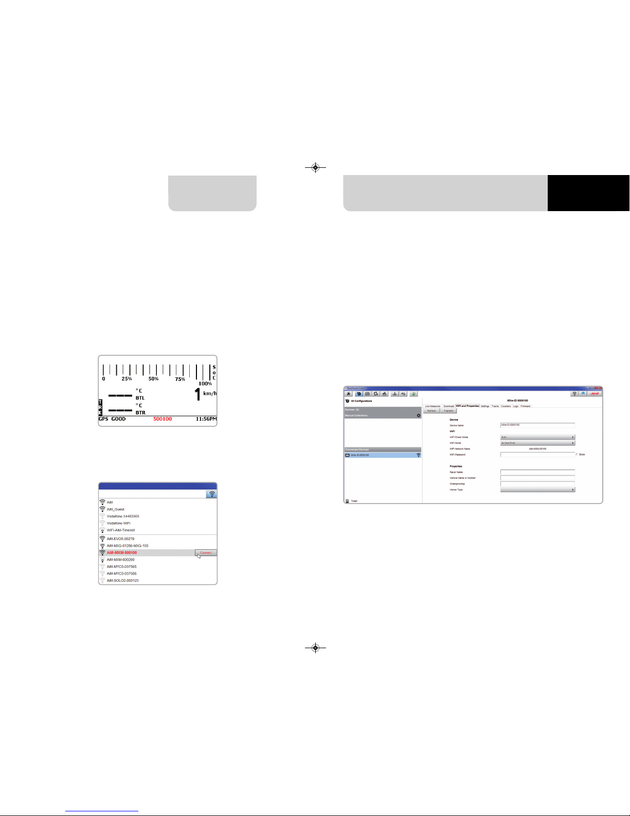
When the PC is authenticated to the network called “AiM” it can see all devices you
configured to access the same network. In the image below two AiM devices are
connected to the same “AiM” WLAN.
Here above you see a device “MXm ID 6500100” that switched from AP to WLAN mode
(Existing Network).
Network name is “AiM” and does not work with free access because is protected by a
password
MANUALE MXm 1.00 2018.qxp_Layout 1 01/08/18 15:08 Pagina 27
Page 15

CHAPTE R 6
28 29
MX UTV
6.1.4 Wi-Fi network settings
In this chapter, you find a short description of how to configure a WLAN including
AiM devices and a PC.
Here below is an example of configuration.
The parameters for the device network configuration in this example are:
n
Wireless network name: Network_1
It means that the WLAN network name is “Network_1.” A PC has to be
authenticated in this network to interact with any AiM device of this network.
n
Gateway address: 192.168.0.1
primary DNS server: 0.0.0.0
secondary DNS server: 0.0.0.0
(These settings prevent Internet connectivity on this WLAN)
n
Subnet mask: 255.255.255.248
Enable DHCP server: yes
DHCP IP address range: 192.168.0.2 to 192.168.0.6
These settings enable a DHCP server running on this WLAN and provide an IP address
in a 2-6 range. This means that this network allows 5 network hosts.
The number of devices on a WLAN network depends on the subnet mask. Here below
you see typical examples of network masks and IP addresses range.
The configuration in bold is the one we suggest (if a greater number of devices is not
needed), being the one that makes it easier and quicker for Race Studio 3 the identification of the devices in the network.
For better network performances, we suggest the use of a network device equipped
with a DHCP server and using 3x3 MIMO technology like, for example a Linksys
AS3200.
To maximize the bandwidth, you should not allow the Internet on this WLAN; this
means the DHCP server should be configured without any DNS address nor gateway
by default.
Subnet mask:
255.255.255.0
255.255.255.128
255.255.255.192
255.255.255.224
255.255.255.240
255.255.255.248
IP address range:
192.168.0.1 – 254
192.168.0.1 – 126
192.168.0.1 – 62
192.168.0.1 – 30
192.168.0.1 – 14
192.168.0.1 – 6
Number of devices:
254
126
62
30
14
6
MANUALE MXm 1.00 2018.qxp_Layout 1 01/08/18 15:08 Pagina 29
Page 16

CHAPTE R 6
30 31
MXm
6.1.5 The Internet connectivity
For an optimal speed of your AiM device(s) we recommend not to allow the Internet
on the same network and to set the WLAN in the same way.
You can of course allow the Internet access on your network but this would degrade
the communication.
This slightly slower speed can be suitable for your needs but you can also have a
second Wi-Fi connection using an additional hardware (NIC).
This configuration would provide an optimal speed of the data network of your AiM
device(s) and at the same time would provide an internet connectivity with the
second NIC.
6.1.6 Connection issues
It can occur that MXm is correctly connected to Race Studio 3 via Wi-Fi but the user
interface does not show it. This may be because Wi-Fi port setting is set with a static
IP. To switch it to dynamic (DHCP):
n
open “Network and sharing centre” in the WindowsTMresearch engine
n
right click on the Wi-Fi connection and a panel shows up
n
select “Properties” option
n
double click on “Internet Protocol version 4 (TCP/IPv4)”
n
verify that option “Obtain an IP address” is active
For further information refer to FAQ section, Wi-Fi of www.aim-sportline.com.
6.1.7 Working on Mac™ with virtualized Windows™
Race Studio 3 only works on WindowsTMoperative systems; Mac users can use a
virtualized Windows
T
M
machine.
The main problem is that the host OS (Mac) must share its Wi-Fi interface with the
virtualized operative system (Windows) as Ethernet interface and not as Wi-Fi
interface.
Configuring Parallels(™)
Select “Menu -> Configure…”
in Parallels.
Press “Hardware” – top on the page
that shows up – and select “Network”
in the drop-down menu on the left.
Right on the configuration panel set
"Type" field on “Wi-Fi”.
Then select the device you want to
communicate with.
MANUALE MXm 1.00 2018.qxp_Layout 1 01/08/18 15:08 Pagina 31
Page 17

CHAPTE R 6
32 33
MXm
To ensure that the communication
works select
“Open Network preferences…” menu.
Verify that the status in the window that shows up is “Connected” and that the IP
address associated is, for example, 10.0.0.10 (could be 10.0.0.11, 10.0.0.12, or
generically 10.0.0.x).
To enable Race Studio 3 correctly working on a Mac with virtualized WindowsTM:
n
press Wi-Fi icon
n
select “Wi-Fi Settings…” icon
n
enable the checkbox shown here below.
MANUALE MXm 1.00 2018.qxp_Layout 1 01/08/18 15:08 Pagina 33
Page 18

CHAPTE R 6
34 35
MXm
6.1.8 Connected device visualization issues
It may occur that using Race Studio 3 on an iMac with virtualized Windows the device
connected via Wi-Fi takes some time to be shown in the network or is not shown at
all. This is why we always suggest using an Wi-Fi (WLAN) router.
This router work as an Access Point allowing more external devices to connect to its
network. MXm Wi-Fi configuration is to be set on Existing Network as explained before.
6.2 Configuration of MXm
Once MXm connected to the PC
n
click “Configurations” icon and configurations page appears
n
click “New” and new configuration panel appears: select “MXm” and press “OK”.
6.2.1 – Channels configuration
“Channels” layer opens; all channels are disabled by default. Here you can set all MXm
channels.
To set a channel just click on its line and the related panel shows up. Speed 1 and 2
and the four Analog channels are disabled by default. First thing to do is enabling
them.
MANUALE MXm 1.00 2018.qxp_Layout 1 01/08/18 15:08 Pagina 35
Page 19

CHAPTE R 6
36 37
MXm
To set Speed channels click on the row and a setting panel appears. In addition to
sampling frequency, unit of measure and display parameters, you can choose:
n
Function: Vehicle speed, Angular velocity, Speed, Turbo RPM
n
Sensor: Speed sensor or ABS speed
n
Speed parameters in the proper bottom box
Please note: if you set one speed as ABS Speed the second will switch to ABS speed
too as shown here below.
To set the four Analog channels click on the related row, a setting panel appears and
you can choose function, sensor type, measure units, display precision or specific parameters.
6.2.2 ECU Connection and configuration
MXm can be connected to your vehicle ECU. When possible documents explaining
how to connect your MXm to your vehicle ECU are published on our website
www.aim-sportline.com. As explained, MXm can communicate using all currently
available communication lines: CAN, RS232, K-Line.
To load the ECU protocol in MXm configuration:
n
enter “ECU Stream” tab
n
press “Change ECU” button
n
elect ECU Manufacturer and ECU Model (in the example FORD/ MUSTANG 2010)
n
press OK
MANUALE MXm 1.00 2018.qxp_Layout 1 01/08/18 15:08 Pagina 37
Page 20

CHAPTE R 6
38 39
MXm
6.2.3 LCU-One CAN setting
MXm can be connected to AiM LCU One CAN lambda controller plugging the 5 pins
male Binder connector of LCU one in the female one of MXm 37 pins harness cable
labelled “EXP”.
Once the expansion connected you need to set it:
n
enter “LCU-One CAN” tab
n
press “ADD” button; it switches to “Remove”
n
name your LCU One and fill in its serial number or press “Get SN from a connected
expansion” to receive the serial number from the connected LCU-One
n
select the multiplier to calculate AFR from lambda
(in the example “14.57 Gasoline”) or add a custom value pressing
“Add Custom Value” (the related panel shows up)
n
set the LCU One channels double clicking on each channel and setting the panel
that shows up.
6.2.4 Math channels
Here you can create math channels; available options are:
n
Bias: considering a relation between two mutually compatible channels it
computes which one is prevailing (typically used for suspensions or brakes);
n
Bias with threshold: it needs the user to set a threshold value for the considered
channels; once these threshold values are both exceeded the system makes the
calculation;
n
Calculated gear: it calculates the gear position using engine RPM and vehicle speed
n
Precalculated gear: it calculates the gear position using Load/Shaft ratio for
each gear and for the vehicle axle too
n
Linear correction: typically used when a channel is not available in the desired
format or if it is wrongly tuned and cannot be tuned again.
Each option asks the user to fill in a proper panel.
MANUALE MXm 1.00 2018.qxp_Layout 1 01/08/18 15:08 Pagina 39
Page 21

CHAPTE R 6
40 41
MXm
In the example below the user created a Status variable called “Water Temp Alarm”.
The status variable can also be logged checking “add to the device logged channels”
checkbox thereby working as an analog channel. Mousing over the status variable a
summary panel appears on the right.
6.2.5 Status variables setting
Here you can set Status variables.
Status variables are user defined conditions that can be used in different situations.
This means that when setting an alarm in “Shift lights and Alarm page” you can set
different alarm including each the same condition (status variable) simply recalling
it from the list.
Pressing “Add New Variable” the related panel appears.
MANUALE MXm 1.00 2018.qxp_Layout 1 01/08/18 15:08 Pagina 41
Page 22

CHAPTE R 6
42 43
MXm
Parameters page is divided in two parts.
n
on top GPS Lap detection parameters; mousing over the question marks a pop
up message will explain you the working mode of:
n
hold lap time for: the time period for which lap time is shown on your
MXm display
n
the track width: width that will be considered for any GPS point you set
n
bottom Start data recording conditions;
n
standard conditions (default setting) make MXm start recording when RPM
is higher than 500 or speed is higher than 10 km/h and switches MXm Wi-Fi off
n
custom conditions: you can set two conditions and decide if making MXm start
recording when only one of them is reached (“ANY”) or when both are satisfied (“ALL”);
pressing the button it sets the condition as shown here below.
6.2.6 Parameters settings
In this page you can set shift lights (on top) and set the alarm led (bottom) of your
MXm.
6.2.7 Shift Lights and Alarms
MANUALE MXm 1.00 2018.qxp_Layout 1 01/08/18 15:08 Pagina 43
Page 23

CHAPTE R 6
44 45
MXm
On top you can set your MXm shift lights working mode. Available options are shift
lights (default) and predictive time.
Use as gear Shift Lights. To use the led bar as shift lights click the setting icon ( )
and the related panel shows up.
You can
n
import/export shift lights setting using the proper buttons
n
decide the sequence mode of the LEDs enabling the desired option:
n
a LED stays on if its threshold is exceeded
n
a LED stays on until another LED with higher threshold turns on or
n
link the shift lights to the engaged gear enabling the related checkbox; in this last
case you need to fill in max gear number and set LEDs colours and threshold values
for each gear.
Use for predictive time. To use the LED bar for predictive lap time enable the related
option and press the setting icon ( ).
You can
n
import/export shift lights setting using the proper buttons
n
decide the sequence mode of the LEDs enabling the desired option:
n
a LED stays on if its threshold is exceeded
n
a LED stays on until another LED with higher threshold turns on or
n
fill in the predictive time increment of each LED. The LED value indicates the time
gap to be assigned to each LED. Assuming you fill in “0.1” and your lap time is improving of 0.3 sec toward the reference lap, your MXm will switch on 3 LEDs green; if, on
the contrary, your lap time is worsening the LEDs will switch on red.
The lap considered as reference is the best one of the current session.
MANUALE MXm 1.00 2018.qxp_Layout 1 01/08/18 15:08 Pagina 45
Page 24

CHAPTE R 6
46 47
MXm
Create and set MXm alarm
As for any AiM logger you can import/export alarms using the related buttons but
you can also create new ones.
To create a new alarm press “+ Add new Alarm”
To set the new alarm:
n
fill in description box on top of “Create New Alarm Panel” (1)
n
press the arrows you find on the left of “Create new alarm “ panel (2)
n
“Select Channel” panel shows up on the right
n
as you can see in the image below if you set a status variable (Water Temp Alarm
in the example) you find it in the available channels list: select the channel
you prefer (3) and press “OK”
n
decide which action is to be trigged (4) among displaying a message or a timed
popup message, display a measure, switch a LED on or activate an output signal
(Power output page, see the related paragraph)
n
decide the alarm ending condition (“Until” – 5) among condition no longer met,
the device is turned off, a button is pushed or data are downloaded
n
“+” buttons you find right of the panel are to add new alarms (the top one) or
to add new actions to an alarm (bottom one)
n
when all operations have been performed press “Save” in “Create New Alarm Panel”
and you will come back to “Shift Lights and Alarm” page
MANUALE MXm 1.00 2018.qxp_Layout 1 01/08/18 15:08 Pagina 47
Page 25

CHAPTE R 6
48 49
MXm
Bottom of the page an Alarm summary is shown. Right clicking on the setting icon,
right of the alarm row you can edit to modify or delete the alarm.
Editing the alarm its “Modify Alarm” panel shows up on the right as in the image
below.
MXm features 2 Power outputs, that can drain up to 15 Amp each. The power outputs
connector, highlighted here below, is a four pin connector.
Each Power output is managed by three channels:
n
the output (ON or OFF)
n
the drained current
n
the Status (OK, Shortcut, Overcurrent, Open Circuit)
Pin Function
1 High side output2
2 9-15V power input
3 9-15V power input
4 High side Output1
6.2.8 Power Outputs setting
MANUALE MXm 1.00 2018.qxp_Layout 1 01/08/18 15:08 Pagina 49
Page 26

CHAPTE R 6
50 51
MXm
To set the two power outputs:
n
enter Power output page
n
mouse over the power output you want to set
n
setting icon appears on the right of the power output row: click it
The setting panel appears: fill it in. In the example Power output 1 has been configured to manage a fan: it turns ON when Water temperature is greater than 90°C: Max
accepted current (Maximum value of requested Loan) is 8 Amp: over this value the
output circuit opens and the read status becomes “Overcurrent”.
6.2.9 Display settings
MXm can have up to eight pages to be set via software. Each page can have from 1
to 4 fields and can be set as you prefer.
n
enter “Display” tab
n
a panel shows up where you can select the display page you prefer
(in the example a four fields page with bar graph has been chosen)
n
select the page and press “OK”
n
repeat the operation for the number of pages you want to set
MANUALE MXm 1.00 2018.qxp_Layout 1 01/08/18 15:08 Pagina 51
Page 27

CHAPTE R 6
52 53
MXm
When the page has been selected two setting panels appears bottom of the page:
n
on the left a panel that shows as many rows as the fields to be set
(in the example 5 fields)
n
on the right a panel shows the channels group you can set in that field and all the
channels in it included; you can drag and drop the channel you want to set in the
desired field or double click on it
n
if you added more display pages the one you are setting is indicated top of the tab
as highlighted here below.
MXm can be connected to AiM SmartyCam to show the data you wish on SmartyCam
video. To set each channel:
n
click on it and a setting panel shows up
n
it shows all channels and/or sensors that fits the selected function
n
in case you do not find the channel or the sensor in the list enable “Enable all
channels for functions” checkbox and all channels/sensors will be shown
n
once all channels set your configuration is finished: press “Transmit” on the page
top keyboard
6.2.10 SmartyCam stream setting
MANUALE MXm 1.00 2018.qxp_Layout 1 01/08/18 15:08 Pagina 53
Page 28

CHAPTE R 6
54 55
MXm
6.3 Managing a track on MXm with Race Studio 3
With Track Manager function of Race Studio 3 you can create, delete and modify
tracks, transmit and receive them to/from your MXm. Press “Tracks” icon.
The main page is divided in three columns; on the left:
n
on top, the filters that allow to collect many tracks following customized criteria;
by default, all tracks are shown (light blue “All Tracks” filter in the image below).
n
bottom left, the connected devices (in the image, “MXm ID 6500100”)
The column in the middle shows:
n
on top a fast search bar, that allows to select the tracks which satisfy your personal
research criteria; by pressing “?”a pop-up window explains research criteria
(highlighted in red below), where:
n
long name is the name you see in bold in each track box
n
short name is the track name shown on the display of your MXm and is
the name you find top right of each track box
n
track city is the name of the city the track is located in
n
all the tracks listed in Race Studio 3 database. It automatically updates at start up
if a connection to the Internet is available.
The column on the Right shows:
n
the data sheet of the track you are mousing over.
MANUALE MXm 1.00 2018.qxp_Layout 1 01/08/18 15:08 Pagina 55
Page 29

CHAPTE R 6
56 57
MXm
When your MXm is connected it is shown on the left bottom part of the page as said
before. Clicking on it all the tracks it contains are shown in the right column of the
page. The tracks you created are labelled “user ” in red.
n
New: create a new track
n
Import: import one or more tracks you stored in your MXm or in another external
device
n
Export: export one or more tracks to a specific PC folder or to another peripheral
device
n
Receive: receive from your connected MXm the tracks you created
(if no device is connected the button is disabled)
n
Transmit: transmit one or more tracks form the PC to your connected MXm
(if no device is connected the button is disabled)
n
Delete: delete one or more tracks from Race Studio 3 Database
n
Refresh: refresh the track list stored in your connected MXm
n
Delete: delete one or more tracks from your MXm memory
n
Delete All: delete all tracks stored in your MXm memory
n
Save all: save all the tracks stored in your connected MXm; it creates a zip file you
can load to another AiM device
n
Load Saved: load the tracks you previously saved in your connected MXm
memory
The keyboard you find above the central column allows you to:
The keyboard you find above the right column allows you to:
The page keyboards are used to manage the tracks.
MANUALE MXm 1.00 2018.qxp_Layout 1 01/08/18 15:08 Pagina 57
Page 30

CHAPTE R 6
58 59
MXm
As said before, your MXm detects if the track it is racing on is not included in its database and it starts recording in “learning” mode. At the end of the session you can
connect the logger to the PC to add the track map to your PC database.
n
click the device name bottom left of Race Studio 3 page
n
select the track map and press “Receive”: the track map appears in the central
column list
n
right click on the map and select “Edit option”
A page for adding some useful information appears. It may be useful to know that:
n
“Track name short” is the name you will see on your device
n
“Circuit type” and “Road surface”, even if not necessary to set the track, are used by
the research filters.
It is possible to change the start line position (move the cursor and set “Cursor Position”) and to add split points in order to organize the track in different segments. This
will be used in Data Analysis.
Press “Save” and the new track will appear in the list labelled “User”.
Since the software is constantly updated, may be other information or features will
be available soon. Please check our website www.aim-sportline.com documentation
area software section “Track Manager” manual.
MANUALE MXm 1.00 2018.qxp_Layout 1 01/08/18 15:08 Pagina 59
Page 31

CHAPTE R 6
60 61
MXm
If your vehicle ECU is not included in Race Studio 3 software you can use CAN Driver
builder to create your own CAN protocol. Press CAN Protocols button shown here
above and then “New”. The panel shown below appears.
You can add a new ECU Manufacturer and/or a new ECU model.
Please note: this Race Studio function is for expert users only and a CAN Driver builder user manual can be freely downloaded from AiM website at www.aimsportline.com, documentation area software/firmware section.
Clicking your MXm bottom left of the software page you enter the device window
and have these options:
n
Live Measures: to check all MXm channels;
n
Download: to download data, see the related chapter;
n
Wi-Fi and Properties: to manage the Wi-Fi configuration – see the related paragraph;
n
Settings to:
n
set date format
n
enable/disable daylight time
n
set time format and time zone
n
set backlight colour
n
enable/disable night vision
n
Tracks: to manage the tracks stored in the device memory
n
Counters: to set each user odometer decimal places as well as reset it
n
Logo: transmit/receive the logo that shows up when switching MXm on;
supported image format are JPEG or BMP; always use the most recent Windows
TM
versions (Windows8 or Windows10) whose graphic libraries are more updated
n
Firmware: to check or update your MXm firmware version.
6.4 ECU Driver builder 6.5 The device window
MANUALE MXm 1.00 2018.qxp_Layout 1 01/08/18 15:08 Pagina 61
Page 32

CHAPTE R 7
CHAPTE R 8
62 63
MXm
Some MXm pages are available for online visualization. To scroll them press “NEXT.
Pages can change according to the device configuration.
At very first switch on, when you quit track page MXm shows by default Laptime
Page; afterwards it will show the last page you displayed.
As said before, MXm can show up to eight custom pages to be configured using Race
Studio 3 software; use “>>” button to scroll among them.
This is the first page that appears when
you switch MXm on and can be recalled pressing “TRACK” button that appears on the left of the logger home
page. When you start the engine of
your car it goes away automatically. It
shows:
• on the left the selected track;
you can select a new one manually or
automatically (“MENU”/ Track Management); in case of “Automatic” selection
the track is selected according to the
coordinates of your vehicle; in case the
track you are running on is not included in your MXm database the laptimer switches to “learning mode” as
shown in the bottom image here on
the right
• on the right the satellite bar
(visible satellites and signal level of
each one) useful to evaluate the status
of GPS signal.
First is “Summary” page.
Select the session you want to see and
press “ENTER”
Once the session selected you see all
tests in a box showing time of the test
and best lap of the test.
Select the test you want to see and
press “ENTER”.
Here you see the three best lap of the
test with max speed value of each lap.
Press “PAGE”.
7 On the track
At the end of the test you can recall sampled data pressing “MEM”.
8 Data recall
7.1 Track page
7.2 Other pages
MANUALE MXm 1.00 2018.qxp_Layout 1 01/08/18 15:08 Pagina 63
Page 33

CHAPTE R 8 CHAPTER 9
64 65
MXm
Once MXm-PC connection is established activate “Download” tab to download sampled data
This page shows all information about the files stored in the system: number of laps,
best lap, date/time and file dimensions.
Select one or more files and press “Download” to download and analyse them.
This page is a histogram test summary.
Moving the cursor left and right you
can see all laps and the difference versus the best lap of that test.
Lap page shows lap time with speed
max/min values.
9 Data download
MANUALE MXm 1.00 2018.qxp_Layout 1 01/08/18 15:08 Pagina 65
Page 34

CHAPTE R 10
66 67
MXm
Select your file double clicking on it and start analysing it. A lot of pages, graphs and
images will help you analysing your data in the best way.
10 Data Analysis
When data have been downloaded press Analysis icon and Race Studio Analysis software will open showing this page.
MANUALE MXm 1.00 2018.qxp_Layout 1 01/08/18 15:08 Pagina 67
Page 35

CHAPTE R 11 CHAPTE R 12
68 69
MXm
MXm can receive RPM value from the ECU. If on the contrary your vehicle does not
have an ECU you can sample RPM using the wire labelled “RPM” of 37 pins connector
harness you find in the kit.
To get the RPM from the ECU you only need to connect your MXm to the ECU and it
will automatically sample that value.
The output labelled “GRAY TACH” gives a 5-50V output that can be directly sampled
by MXm.
11 New firmware upgrade 12 RPM
12.1 RPM from ECU
If your vehicle has no ECU you need to connect the wire labelled ” RPM” of 37 pins
connector harness to the ignition system. This way MXm can read the signal form the
low voltage of the coil (whose peak can be from 150 to 400 V) or from a possible
square wave (the peak can be from 5 to 50 V).
The image below shows an example of wiring of the ignition system.
12.2 RPM via a 5-50V square wave or coil
(150-400V)
Our technicians and engineers are constantly working to improve both the firmware
(the application that manages your device) and the software (the application you install on your PC).
Each time a new firmware and/or software version is available the icon here above
appears with an arrow indicating that something is available for download (otherwise
the icon only shows the cloud).
Click it and freely download the new applications.
Once the new firmware has been downloaded connect your device to the PC via
Wi-Fi to perform a firmware upgrade. In a few seconds the device is ready.
MANUALE MXm 1.00 2018.qxp_Layout 1 01/08/18 15:08 Pagina 69
Page 36

CHAPTE R 12
70 71
MXm
In case the vehicle ignition system has no output you need to connect MXm to the
low voltage of the coil as shown in the following images.
Point 1: low voltage of the coil
Point 2: connected to the spark plug
Point 3: connected to the +12V of the battery
Once MXm connected to RPM signal you can set its parameters in channels page of
Race Studio 3 as explained in “Channels configuration” paragraph.
MANUALE MXm 1.00 2018.qxp_Layout 1 01/08/18 15:08 Pagina 71
Page 37

CHAPTE R 13
72 73
MXm
Your MXm can be connected to AiM SmartyCam HD, SmartyCam GP HD and LCUOne CAN as shown in the images below.
Please remember that all channels transmitted by these AiM expansions have to be
set in Race Studio 3 software as already explained in the related paragraphs (“LCUOne CAN setting” and “SmartyCam stream setting”).
Moreover for further information concerning SmartCam HD, SmartyCam GP HD and
LCU One refer to the related manuals you can download from “Documentation” area
of AiM website www.aim-sportline.com.
To connect MXm to SmartyCam HD connect SmartyCam CAN cable to the cable labelled “EXP” of MXm 37 pins connection harness and 7 pins Binder connector of SmartyCam CAN cable to 7 pins Binder connector placed rear left of SmartyCam HD as
shown here below.
To connect MXm to SmartyCam GP HD connect SmartyCam CAN cable to the cable
labelled “EXP” of MXm 37 pins connector harness and 7 pins Binder connector of
SmartyCam HD CAN cable to the recorder central connector as shown here below.
To connect MXm to LCU-One CAN connect cable labelled “EXP” of MXm 37 pins
connector harness to 5 pins Binder connector of LCU-One as shown here below.
13 Connection with SmartyCam and LCU-One
MANUALE MXm 1.00 2018.qxp_Layout 1 01/08/18 15:08 Pagina 73
Page 38

CHAPTE R 14
74 75
MXm
14 Technical specifications and drawings
n
Display resolution
n
Display pages
n
Backlight
n
Ambient Light sensor
n
Shift Lights
n
Alarm LEDs
n
CAN connections
n
Analog Inputs
n
Digital Inputs
n
Digital outputs
n
Integrated track database
n
Inertial platform
n
Wi-Fi connection
n
Integrated GPS
n
ECU connection
n
External power
n
Internal memory
n
Pushbuttons
n
Connectors
n
Body
n
Weight
n
Dimensions
n
Waterproof
n
Analysis software
268x128 pixel
Up to 8 freely configurable
7 configurable RGB colours
Yes
5 freely configurable RGB LEDs
2 freely configurable RGB LEDs
2
4 fully configurable max 1.000Hz each
2 speed inputs, coil RPM input
2 hight side
Yes
9 axis internal platform
Yes
10Hz GPS+Glonass
CAN, RS232, K-Line
12V
4Gb
Metallic
37 pins motorsport connector
+ 4 pins power connector
Glass fiber reinforced Nylon
330g
137x88,4x31,9 mm
IP65
Race studio analisys freely downloadable from
www.aim-sportline.com
MANUALE MXm 1.00 2018.qxp_Layout 1 01/08/18 15:08 Pagina 75
Page 39

76 77
MXm
MXm Pinout MXm 37 pins Deutsch connector harness
MANUALE MXm 1.00 2018.qxp_Layout 1 01/08/18 15:08 Pagina 77
Page 40

78 61
MXm
Our web site, www.aim-sportline.com is
constantly updated.
Please, refer to it for downloading the last
release of our documentation.
MANUALE MXm 1.00 2018.qxp_Layout 1 01/08/18 15:08 Pagina 79
 Loading...