

Page 1
Suzuki GSX-R K3
Plug&Play kit
User Manual
1
Page 2

MXL P&P SUZUKI GSX-R K3
User Manual
Release 1.07
SUMMARY
Preface ................................................................................................................................ 4
1 – Kit description .............................................................................................................. 5
1.1 – Part Numbers (see Appendix “A”) .................................................................................................... 7
2 – Plug & Play kits installation ........................................................................................ 8
2.1 – Removing the lateral mirrors and the front and lateral fairings .................................................... 9
2.2 – Removing the bike seat and lifting the fuel tank. ......................................................................... 11
2.3 – Releasing the high beam and the front fairing screws. ............................................................... 12
2.4 – Removing the stock dash; unplugging the connectors ............................................................... 12
2.5 – Assembling the kit. .......................................................................................................................... 14
2.6 – Cables connection ........................................................................................................................... 15
2.7 – Installing the kit ................................................................................................................................ 16
2.8 – Installing the TPS cable ................................................................................................................... 17
3 – MXL connection inputs ............................................................................................. 18
4 – MXL GSX-R K3 firmware ........................................................................................... 19
5 – Configuration ............................................................................................................. 20
6 – Gear calibration ......................................................................................................... 25
6.1 – Saving the configuration with custom gear calibration ............................................................... 28
7 – Equivalent circumference compute ......................................................................... 29
8 – TPS sensor configuration ......................................................................................... 30
9 – Channels ..................................................................................................................... 32
10 – Data download and analysis ................................................................................... 33
11 – MXL optional expansions ........................................................................................ 33
11.1 – Appendix “A” MXL for Suzuki GSX-R K3 kit wirings .................................................................. 34
11.2 – Appendix “B” TPS Cable ............................................................................................................... 40
www.aim-sportline.com
2
Page 3

MXL P&P SUZUKI GSX-R K3
User Manual
Release 1.07
PRESENTATION
AIM: a world leader in data acquisition for racing environment.
Established in 1976, AIM is today a world leader in the production of high performances
instruments for racing environment: dashes, data loggers, digital displays, lap timers.
AIM set new standards in various motor sports: from kart to car, bike, dragster, Formula 1
boat, Offshore and even snowboards!
AIM products merges the functionalities of traditional tachometers, RPM indicators,
temperature, pressure and lap timers with compact high performing friendly using units.
Different products for different applications but with one shared characteristic: great
innovation.
Each AIM system is completely designed, produced and tested by its technicians. The
research and development board is made of electronic and mechanical engineers, physics
and other specialists that develop firmware, software, hardware and the related
documentation.
Our fame is build on quality products, innovative technology and faithful commitment in
supporting our customers.
www.aim-sportline.com
3
Page 4
MXL P&P SUZUKI GSX-R K3
•
User Manual
Release 1.07
0
Preface
MXL Plug & Play kit for Suzuki GSX-R K3 is the dashboard (with data logger function in
Pista version) designed for an easy and quick installation: with a minimum effort a straight
connection with the bike ECU is made and a lot of different information (depending on the
logger model) are displayed with no need of additional sensors:
MXL STRADA MXL PISTA
• RPM
• Speed
• Water temperature
• Oil Pressure Signal
• Fuel level
RPM
• Speed
• Water temperature
• Engaged gearl
• 6 free channels
• Turning lights
• High beam
• Engaged gear
• 2 free channels
The logger, like the stock dash, is powered by the bike master switch.
MXL Strada and Pista for Suzuki GSX-R K3 kits have been developed for the following
bike models:
Cubic capacity Year 2003 Year 2004 Year 2005
600
750
1000
√ √ √
√ √ √
√ √
See
K5 manual
√= supported
Note: thanks to the optical IR transmitter/receiver (included in MXL Pista kit, optional to
MXL Strada), lap times will be displayed/recorded.
For any additional information not expressly handled in this tutorial, always refer to MXL
user manual and/or to Race Studio Configuration user manual.
www.aim-sportline.com
4
Page 5
MXL P&P SUZUKI GSX-R K3
User Manual
Release 1.07
1
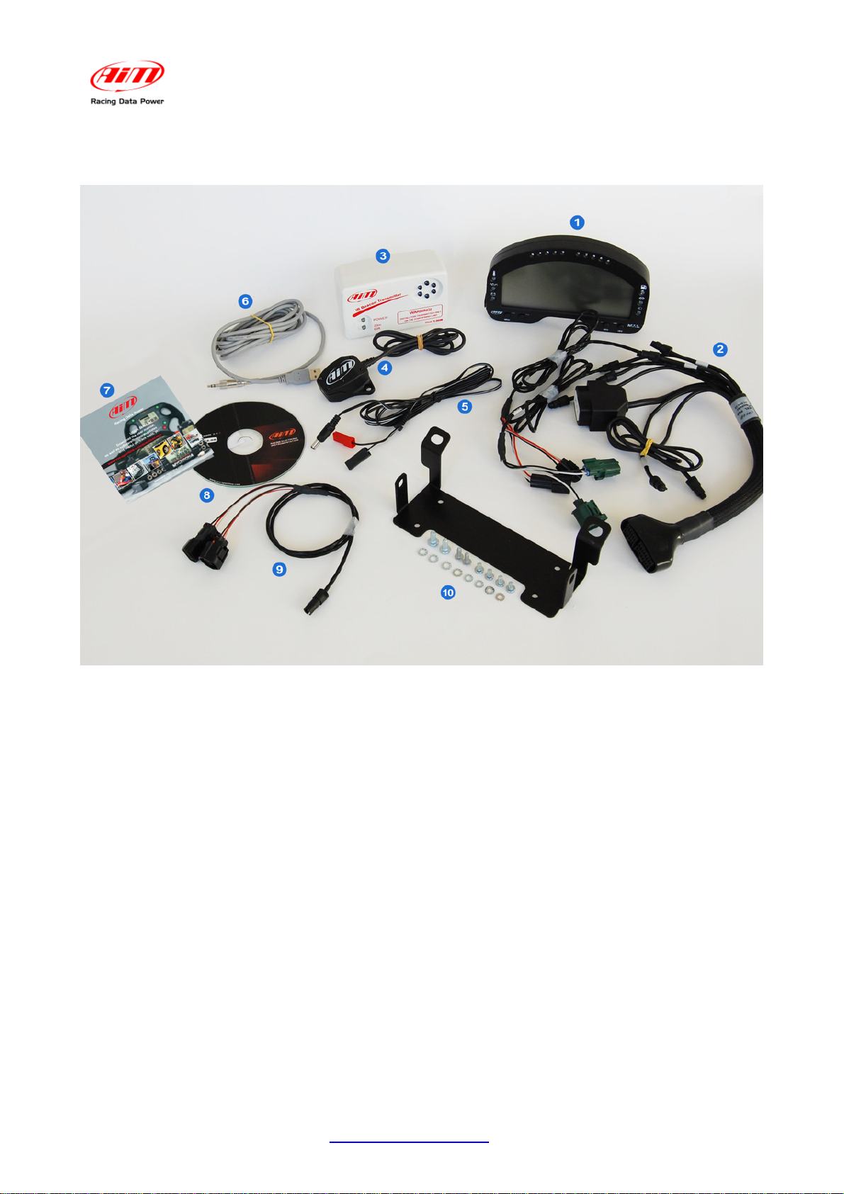
1 – Kit description
Suzuki GSX-R K3 Plug & Play kits differ depending on the version of MXL. Each type of
kit includes some of the objects shown in the above picture, recognizable by their
numbers:
MXL Strada kit:
N.1 – MXL Strada (1)
N.1 – Suzuki GSX-R K3 interface wiring (2)
N.1 – USB cable for MXL (6)
N.1 – Leaflet MXL Suzuki GSX-R K3(7)
N.1 – Race Studio 2 software CD (8)
N.1 – Bracket kit (10) that includes:
n° 4 Phillips 4*8 mm recess screws
n° 2 Phillips 5*12 mm recess screws
n° 4 Grover washers Ø 4 mm
n° 4 washers Ø 5 mm
n° 4 Phillips threading forming recess screws 40*12
www.aim-sportline.com
5
Page 6
MXL P&P SUZUKI GSX-R K3
User Manual
Release 1.07
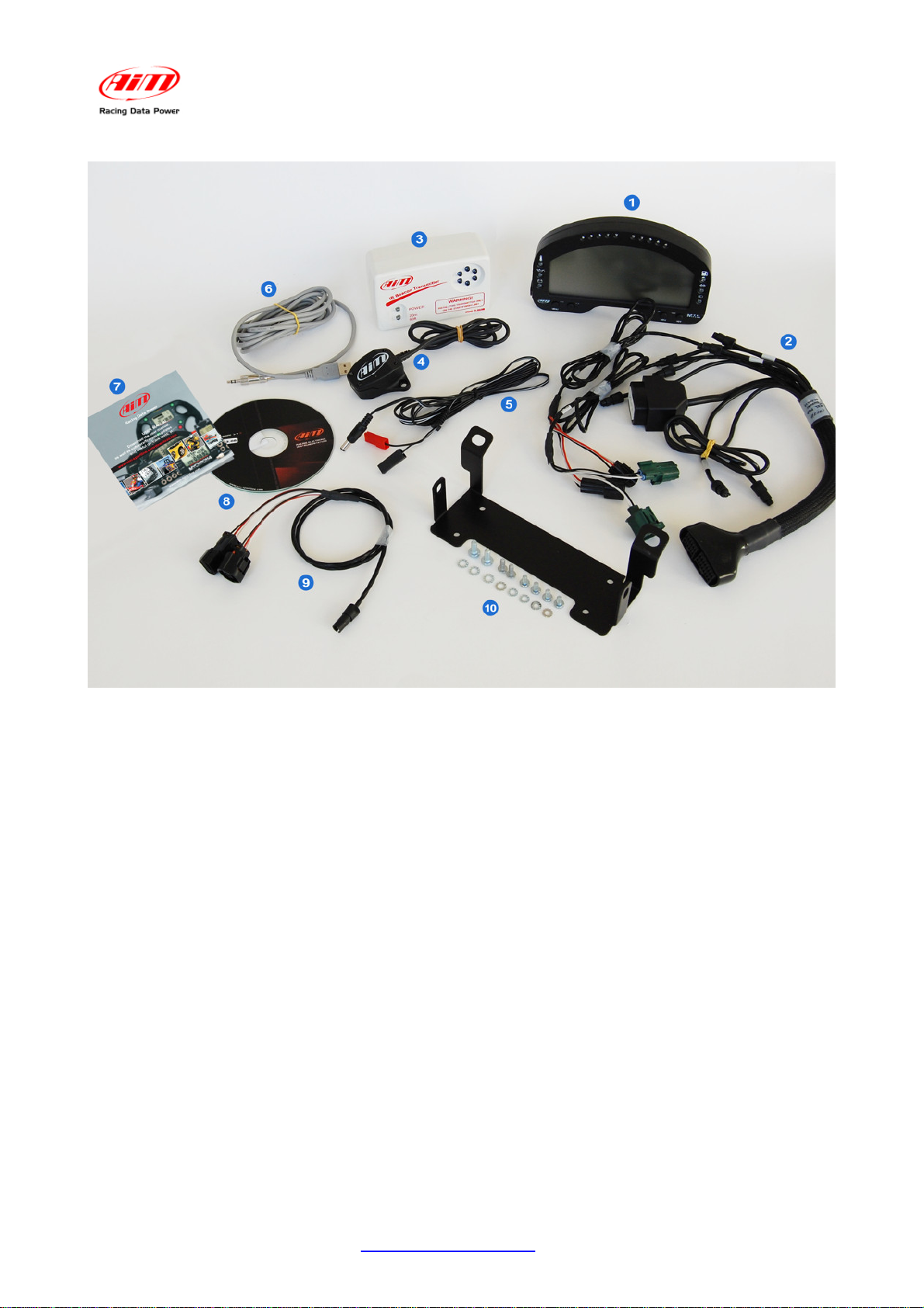
MXL Pista kit:
N.1 – MXL pista (1)
N.1 – Suzuki GSX-R K3 interface wiring (2)
N.1 – IR Transmitter (3)
N.1 – IR receiver (4)
N.1 – Transmitter power cable (5)
N.1 – USB cable for MXL (6)
N.1 – Leaflet AIM products (7)
N.1 – Race Studio 2 software CD (8)
N.1 – TPS – throttle position sensor - cable (9)
N.1 – Bracket kit (10) that includes:
n° 4 Phillips 4*8 mm recess screws
n° 2 Phillips 5*12 mm recess screws
n° 4 Grover washers Ø 4 mm
n° 4 washers Ø 5 mm
n° 4 Phillips threading forming recess screws 40*12
www.aim-sportline.com
6
Page 7

MXL P&P SUZUKI GSX-R K3
User Manual
Release 1.07
Universal kit (for customers that already have an MXL Strada, Pista):
N.1 – Universal interface cable for Suzuki GSX-R K3 (2)
N.1 – Bracket kit (10) that includes:
n° 4 Phillips 4*8 mm recess screws
n° 2 Phillips 5*12 mm recess screws
n° 4 Grover washers Ø 4 mm
n° 4 washers Ø 5 mm
n° 4 Phillips threading forming recess screws 40*12
MXL Strada optional
N.1 – IR transmitter (3)
N.1 – IR receiver (4)
N.1 – Transmitter power cable (5)
N.1 – TPS – throttle position sensor cable (9)
Note: before starting kit installation it is suggested to carefully verify that the kit contains all
listed items.
12
1.1 – Part Numbers (see Appendix “A”)
MXL Strada Plug&Play kit for Suzuki GSX-R600-750 K3 – code X10MXLSGS3467:
• only CAN connection + analog channels;
• technical draw code 04.554.14.
MXL Strada Plug&Play kit for Suzuki GSX-R1000 K3 – code X10MXLSGS3410:
• only CAN connection + analog channels;
• technical draw code 04.554.14.
MXL Pista Plug&Play kit for Suzuki GSX-R600-750 K3 – code X10MXLCGS3467
• only CAN connection + analog channels;
• technical draw code 04.554.13.
MXL Pista Plug&Play kit for Suzuki GSX-R1000 K3 – code X10MXLCGS3410
• only CAN connection + analog channels;
• technical draw code 04.554.13.
Universal kit for MXL Strada Suzuki GSX-R K3 (wiring + bracket) – code V02554140
• to transform an MXL Strada into a Plug&Play application for Suzuki GSX-R K3;
• technical draw code: 04.554.14
Universal kit for MXL Pista Suzuki GSX-R K3 (wiring + bracket): code V02554130
• to transform an MXL Pista in Plug&Play application for Suzuki GSX-R K3;
• technical draw code 04.554.13
Optional to MXL Strada Suzuki K3 kit
• IR receiver: code X41RX12090
• IR transmitter: code X02TXKMA01
• transmitter power cable: code V02POWTX0
• TPS cable – throttle position sensor – Suzuki GSX-R K3: code V02550690
www.aim-sportline.com
7
Page 8

MXL P&P SUZUKI GSX-R K3
User Manual
Release 1.07
2
2 – Plug & Play kits inst allation
Suzuki GSX-R K3 Plug and Play kits have been expressly designed to be real plug and
play systems.
WARNING: these kits have been developed and tested to guarantee maximum
compatibility with the stock bike sold by the manufacturer.
The anchor plugs mounted on the back of the logger allows the user to replace the stock
dash in an easy and quick way with no need of cutting, bending or punching anything:
each component is “Plug and Play”.
The logger needs to be connected to the bike high beam using the bracket that comes with
the kit. The bracket is in black anodized aluminium, lightweight and mechanically resistant.
GENERAL NOTES – Read carefully these instruction before installing the kit.
• Do not cut any cable: the wiring supplied with the kit is Plug & Play.
• Be careful not to damage the stock connectors while plugging/unplugging them; in
the following pages is described how to correctly manage them.
• Do not install the system when the engine is hot: stock connectors are quite near
to the engine and there is burning danger.
• The space under the fuel tank is quite reduced: be careful plugging/unplugging
the connectors.
• Be careful not to lose screws and washers.
• Be careful not to damage the fairings while installing/uninstalling them.
www.aim-sportline.com
8
Page 9
MXL P&P SUZUKI GSX-R K3
User Manual
Release 1.07
18
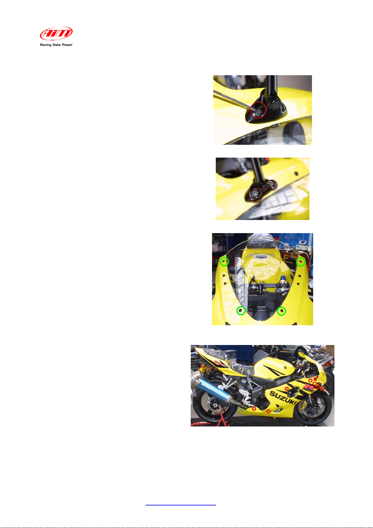
2.1 – Removing the lateral mirrors and the front and lateral fairings
The first installation step is removing
lateral mirrors and front and lateral
fairings.
Lateral mirrors are fixed to the bike
chassis with two hex screws that have a
plastic cover. To remove the covers see
Figure 1.
It is then possible to remove the hex
screws shown in Figure 2.
Both mirrors need to be removed.
Afterwords remove the front screen and
the right lateral fairing.
It is suggested to remove the front screen
to uninstall the stock dash and install the
new one.
The fairing is fixed to the bike with four
Phillips thread forming screws.
Figure 1: plastic covers removal.
Figure 2: hex screws.
In Figure 3 the position of the screws is
shown: remove them.
The logger wiring is to be installed on the
bike right side.
It is only required removal of the right
lateral fairing, fixed to the chassis through
6 hex screws and four plastic pins. Screws
are red circled in Figure 4 while pins are
highlighted by red/yellow arrows in
Figures 4 and 5.
The plastic pin on Figure 4 is only visible
looking at the bike frontally.
Figure 3: front screen – 4 Phillips thread forming
screws.
Figure 4: right lateral fairing – screws and pins.
www.aim-sportline.com
9
Page 10
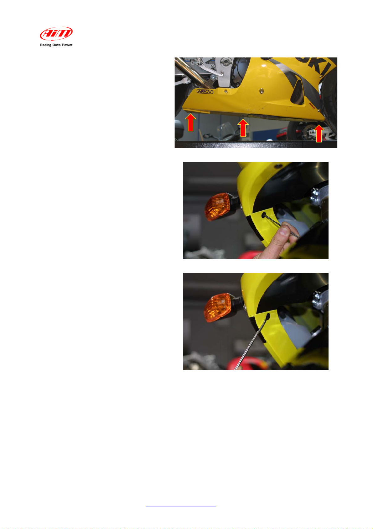
The remaining three plastic pins are on
the bottom part of the bike.
To correctly remove them refer to
Figures 6 and 7.
Insert a tip in the central hole of the pin
and press until you hear a click. This
way the pin is released.
MXL P&P SUZUKI GSX-R K3
User Manual
Release 1.07
Figure 5: Right and left fairings junction – pins position.
Once the pin released it is possible to
remove it. Use a flat screwdriver: insert
under the pin and rotate it.
All the three pins have to be removed.
When all hex screws and pins are
removed the right lateral fairing is
released.
Figure 6: release the central clip of the plastic pin.
Figure 7: removal of the plastic pin
www.aim-sportline.com
10
Page 11
MXL P&P SUZUKI GSX-R K3
19
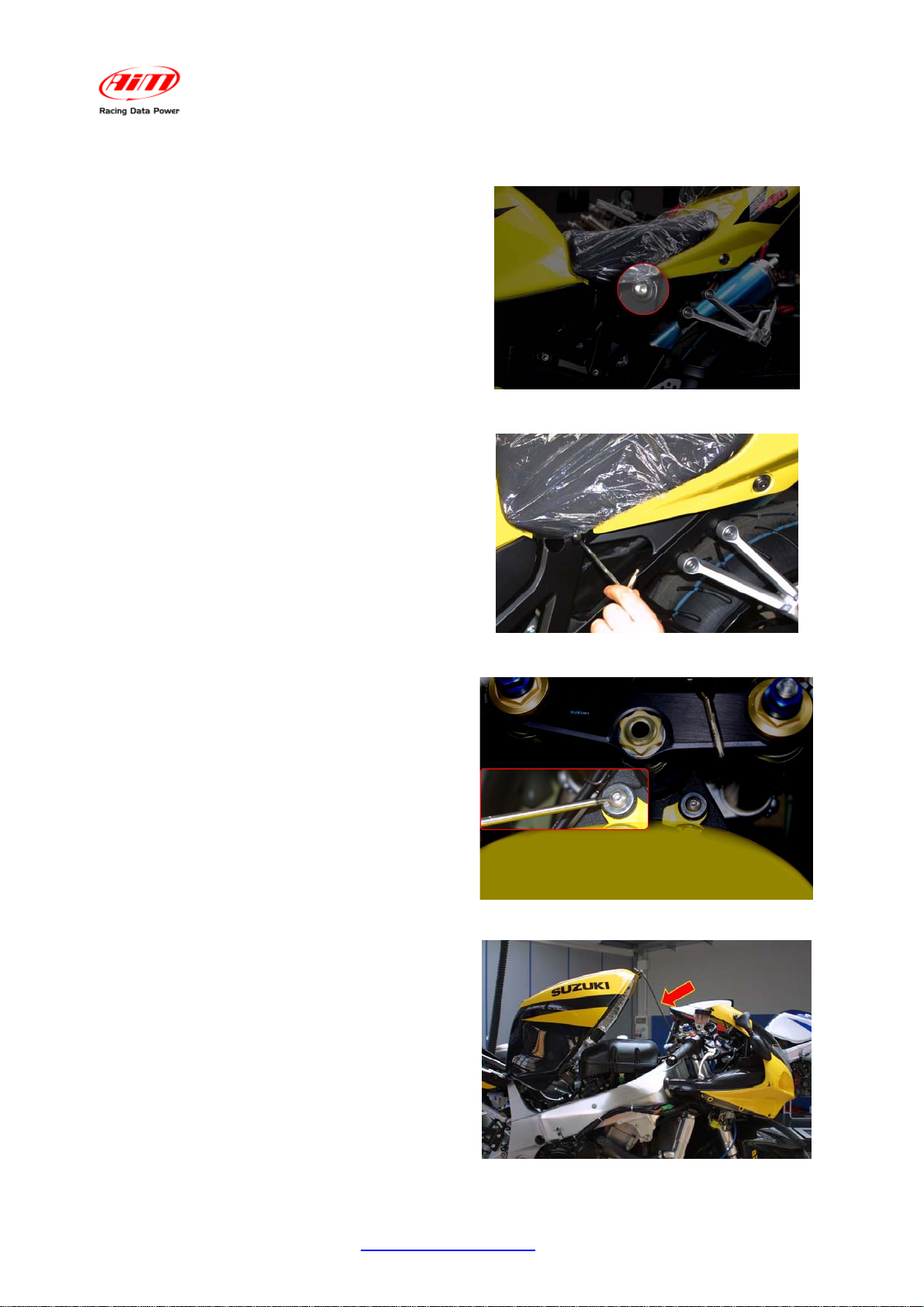
2.2 – Removing the bike seat and lifting the fuel tank.
User Manual
Release 1.07
Some bikes connectors are very near to
the engine and placed under the fuel tank;
it is then required to lift the latter.
To lift it remove the bike seat, which is
fixed to the bike with two screws. In
Figure 8 the left screw is indicated.
Remove the two lateral screws of the bike
seat as shown in Figure 9.
It is now possible to remove the bike seat.
Figure 8: bike seat
The fuel tank is hinged to the chassis near
to the seat and fixed with two hex screws
placed close to the fork. Unscrew them as
shown in Figure 10.
Once the screws are removed, it is
possible to lift the fuel tank using the bike
standard equipment as shown in Figure
11.
Figure 9: unscrew the bike screws
Figure 10: how to remove the fuel tank
www.aim-sportline.com
Figure 11: lifting the fuel tank
11
Page 12
MXL P&P SUZUKI GSX-R K3
d
13
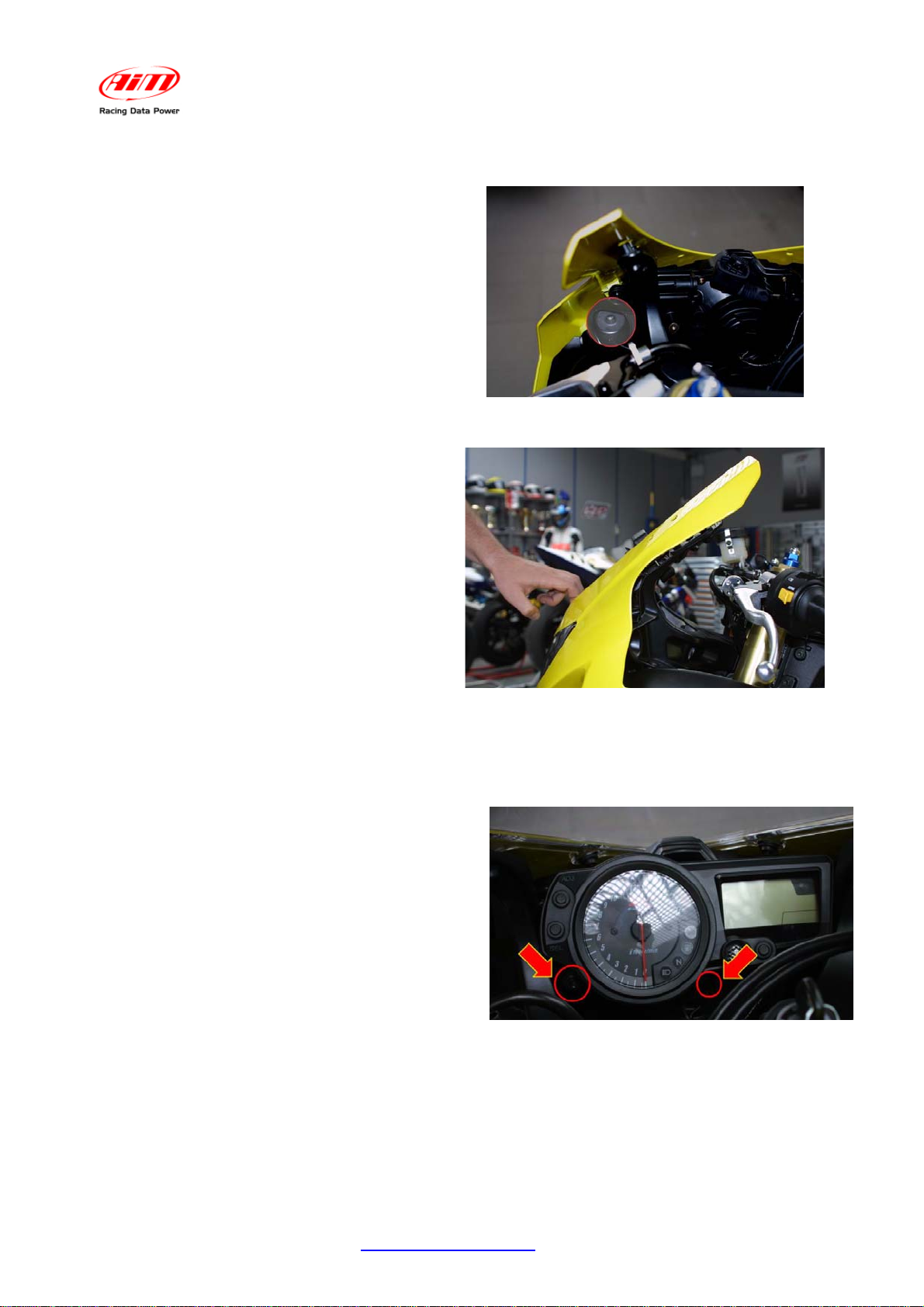
2.3 – Releasing the high beam and the front fairing screws.
User Manual
Release 1.07
The 3
r
installation step is releasing the
high beam and the front fairing screws, to
install more easily the kit. These screws
are self threading Phillips.
In Figure 12 is highlighted one of the two
remaining screws of the fairing.
Note: in the Figure the screws has
already been removed.
Once released these screws, pull (softly)
the front fairing onwards to fix the lateral
screws of the new dash (see Figures 28
e 30 for further information).
While pulling the fairing, pay attention not
to disconnect the high beam that may fall
down.
Note: to pull the fairing onwards, screws
and pins should have been removed.
Figure 12: front fairing and high beam screws
position
14
2.4 – Removing the stock dash; unplugging the connectors
Figure 13: front fairing and high beam screws
released.
The fourth installation step is removing the
stock dash and unplugging the stock
connectors.
The stock dash is fixed to the bike in four
points: with two 5 mm hex screws in the
first two and through a bracket in the other
two.
Remove the hex screws highlighted in
Figure 14.
Figure 14: stock dash front screws posit i on.
www.aim-sportline.com
12
Page 13

Once removed the screws, it is possible to
uninstall the stock dash and rotate it
towards himself and unplug it from the high
beam.
Once removed the stock dash, unplug the
16 pins AMP connector from the back of
the dash.
Remove the plastic cover, press the tongue
(highlighted by an arrow Figure 16) and
unplug the connector from the dash.
MXL P&P SUZUKI GSX-R K3
User Manual
Release 1.07
Figure 15: stock dash removal
Figure 17 shows gear and water
temperature stock connectors default
position.
For further information concerning the
stock connectors refer to Figures from 18
to 19.
The gear connector, shown in Figure 18 is
a 3 pins white connector, usually placed on
the left part of the bike (see Figure 17).
Here below are shown the two gear
connectors: male and female.
Note: cable colours correspond to real
ones.
White connector
Figure 16: unplugging the stock dash conector.
Figure 17: stock connectors position
To the engine
To the ECU
www.aim-sportline.com
Figure 18
: gear connector – particular
13
Page 14

Water temperature stock connector,
Figure 19, is a 2 pins green connector
placed on the left part of the bike (see
Figure 17).
Here below is the water temperature
connector.
NOTE: cable colours corresponds to real
ones.
Green connector
To the ECU
3 pins male/female connector are inserted
one in the other.
MXL P&P SUZUKI GSX-R K3
User Manual
Release 1.07
Figure 19: water temperature connector – particular
To unplug male connector from female one
use a flat screwdriver: push down the
locking tongue and unplug the connectors.
Attention: pull the connectors and not the
cables (they me be seriously damaged)
and unplug each cable from the connector.
15
2.5 – Assembling the kit.
The 5th installation step is assembling the
kit for Suzuki GSX-R.
It has four anti-vibration mountings already
fixed on the back of MXL;
Install MXL on the aluminium bracket: the
bracket needs to be fixed to MXL in
correspondence of the 4 anti-vibration
mountings and with 4 screws and 4
Grover washers.
Figure 20: how to unplug a connector.
Figure 21: anti-vibration mounting – particular
Figure 22 shows the correct assembling
of MXL, bracket and washers (rear view).
www.aim-sportline.com
Figure 22: MXL and bracket – rear view
14
Page 15

16
2.6 – Cables connection
MXL P&P SUZUKI GSX-R K3
User Manual
Release 1.07
The 6th installation step is installing the
wiring supplied with the kit.
The entire wiring is wrapped in a rubber
girdle. Bend it 90 degrees and let it run
along the bike right side.
Follows these instructions to correctly
install the wiring.
Let the wiring (except cable labelled
“Lap”) pass between the high beam and
the front fairing.
The 2 AMP connectors, “Lap” cable and
stock wiring (the one terminating with a
black aluminium box), should remain over
the high beam chassis.
Both AMP connector and black box are
too big to pass between the chassis and
the high beam. It is suggested to insert
the wiring from top.
Figure 23: wiring installation
Figure 24: kit installation
Let the cable labelled “Gear”, “Water
temp” etc… pass along the bike chassis
like in Figure 25. Use plastic wrappers to
fix them to the bike stock wiring.
“Gear” and “Water temp” stock connectors
are under the fuel tank and it is better to
let them enter in the engine compartment
as in Figure 25.
“Gear” and “Ch. 1 Water temp” cables
have two connectors, male and female.
Connect AIM male connectors to female
stock ones and vice versa.
Connect the 16 pins black connector to
the male one in the black aluminium box
(press until a click is heard). Refer to
Figure 26 for further information.
Once the 16 pins connector has been
connected, use the stock dash plastic
cover to make the connection water
resistant.
Figure 25: the wiring runs along the chassis
www.aim-sportline.com
Figure 26: particular of AMP connector
15
Page 16

17
2.7 – Installing the kit
MXL P&P SUZUKI GSX-R K3
User Manual
Release 1.07
The 7th installation step is connecting the
26 pins MS connector to MXL. Once
installed the connector, place the black
aluminium box between the bracket and
the high beam.
When the channels interface box has
been placed (using Velcro or plastic
wrappers), install the kit on the high
beam.
The new dash needs to be fixed in four
points: two of them frontally visible and
two lateral.
Use the M5 screws supplied with the kit
to fix the new dash in the two frontal
points and the Phillips thread forming
screws to fix it laterally.
Figure 27: 4 screws position.
Use the thread forming screws supplied
Figure 28
: position of lateral and bottom wings of the
bracket.
with the kit to fix the new dash laterally
(Figure 29). The screws have to be
inserted in the hole circled in Figure 29.
Note: the front fairing has already
been pulled onwards like in Figure 13.
It is possible to use plastic wrappers to
fix the new wiring to the chassis.
Figure 29: lateral screws fixing
Before remounting lateral fairing, front screen, bike seat and fuel tank, switch the bike on
and check system integrity, its correct installation and proper working.
www.aim-sportline.com
16
Page 17

MXL P&P SUZUKI GSX-R K3
20
2.8 – Installing the TPS cable
Warning: before installing the cable it is necessary to remove the fuel tank, as
recommended in the previous pages.
User Manual
Release 1.07
Unplug the Suzuki stock cable form TPS sensor and connect it to MXL wiring male
connector labelled as TPS (as shown in the image above).
Connect female connector of MXL TPS cable to the TPS sensor (as shown by the blue
arrow).
Connect the 4 pins male plastic Binder connector to one of the free channels depending
on MXL model (See chapter “Channels”).
To configure the channel the TPS sensor is installed on, refer to the related chapter in the
following pages.
www.aim-sportline.com
17
Page 18

MXL P&P SUZUKI GSX-R K3
User Manual
Release 1.07
10
3 – MXL connection inputs
Thanks to interfaces cable supplied with Plug & Play Suzuki GSX-R K3 kit, data
acquisition is really easy and fast.
Here below all connectors that allows the user to display data on MXL are shown:
• Lap connector (left connector), which allows lap time acquisition
• Expansion modules connector (right connector), for all CAN expansion modules
(GPS, Lambda probe) connection
• 2 AMP connectors (12 and 16 pins), which allow communication between the
logger and Suzuki GSX-R K3 ECU.
www.aim-sportline.com
18
Page 19

MXL P&P SUZUKI GSX-R K3
User Manual
Release 1.07
3
4 – MXL GSX-R K3 firmware
MXL Strada/Pista for Suzuki GSX-R K3 is equipped with a special firmware version, that
provides the user with a second virtual dashboard.
On the road, the display is set on “street mode”
and shows these parameters:
RPM graph bar configurable scaling: black
digital RPM value / battery voltage / total and
partial odometer, date and time: fuchsia
(VIEW/QUIT button to switch the options);
Speed: red
Engaged gear: green
Always on top analog inputs depending on MXL
version: blue
Figure 30: Display in modalità strada
Field, until 4 fields displayed two by two: light
blue
To switch the visualization, use “>>” button.
On the track, when passing by a switched on
transmitter, the display switches automatically on
“track mode”.
Lap time takes the place of odometer on the
display (Figure 31).
Figure 31: Display in modalità pista
Visualisation mode (street/track) set via software is stored by the logger. Default setting is
“show odometer”. If user sets via software “Show lap time” this visualisation mode is
restored at each switch on, no matter if the bike is on the road or on track.
Note: for further information concerning the display management and its configuration
refer to MXL Strada/ Pista/Pro and/or Race Studio Configuration user manual.
www.aim-sportline.com
19
Page 20

MXL P&P SUZUKI GSX-R K3
User Manual
Release 1.07
4
5 – Configuration
After MXL installation, the logger is ready to work thanks to the default configuration. In
case a custom configuration is needed, here follows the correct procedure.
Run Race Studio 2 software.
Press “AIM system manager” button on the left vertical keyboard; the panel showing all
AIM systems managed through this software appears: select MXL.
Press New button in system configuration window:
www.aim-sportline.com
20
Page 21

Fill in the window here below.
MXL P&P SUZUKI GSX-R K3
User Manual
Release 1.07
• Data logger type: select MXL Pista or MXL Strada Suzuki GSX-R depending on
the kit.
• New configuration name: fill in a configuration name.
• Vehicle name: fill in a vehicle name.
• Select speeds, temperatures and pressures unit of measure.
• Click on OK button to create the configuration.
Select Channels layer to enter MXL channels configuration:
www.aim-sportline.com
21
Page 22

If an MXL Pista is being configured this window appears:
MXL P&P SUZUKI GSX-R K3
User Manual
Release 1.07
If an MXL Strada is being configured this window appears:
Both of them show the channels sampled by the logger.
: all additional analog channels are disabled by default. To configure them refer to
Note
Race Studio Configuration user manual.
www.aim-sportline.com
22
Page 23

It is now necessary to configure the display.
Select System configuration layer:
This window appears:
MXL P&P SUZUKI GSX-R K3
User Manual
Release 1.07
The following fields have already been set:
RPM: RPM Max value is set on 14000;
Gear sensor: the procedure explained in chapter 6 is required;
Shift light: an engine limiter at 11000 Rpm is expected. If the engine has a limiter with an
higher max value, users need to modify threshold values inserted in the shift lights cases,
so that the last red led switches on just before the limiter intervention.
Speed: the speed sensor of Suzuki GSX-R K3 bike is installed on the jackshaft that
connects the gearbox to the pinion. The number of magnets installed on this jackshaft is 4.
The wheel circumference written in the proper cell is an “equivalent circumference”
calculated using the following formula:
NCircumfWheel
*
p
CircumfEquiv
=
N
c
Np = pinion teeth number
Nc = crown teeth number
Using the default values for crown/pinion teeth number and wheel circumference for a
Suzuki GSX-R K3 750, the equivalent circumference is 801.4 (31.55inches).
If the pinion or the crown are changed and the new one has a different teeth number,
equivalent circumference needs to be re-computed.
For the automatic compute of the wheel circumference, please refer to “Equivalent
circumference compute” paragraph.
www.aim-sportline.com
23
Page 24

MXL P&P SUZUKI GSX-R K3
User Manual
Release 1.07
Displayed channels are:
ECT: water temperature; threshold value: Low (Min) 50° / High (Max) 90°.
ODOMETER: by default it is set on show odometer. Once on the track (with optical lap
receiver and transmitter) the logger switches automatically on “Show lap time” mode.
Switching on/off the MXL the logger shows again odometer.
Note: To modify and customize displayed channels refer to Race Studio Configuration
user manual.
This way the configuration is ready and can be transmitted to MXL: to do so press
“Transmit” button on the top keyboard.
www.aim-sportline.com
24
Page 25

MXL P&P SUZUKI GSX-R K3
User Manual
Release 1.07
5
6 – Gear calibration
Gear calibration is the last system configuration step.
This procedure is to be done only if the default one does not allow correct visualisation of
the engaged gear number.
This procedure can only be done using a PC with Microsoft XP or Microsoft Vista
operating system and Race Studio 2 software (included in the kit) installed. The logger
has to be connected to the PC through the proper USB cable supplied with the kit and
switched on.
Once the PC connected to MXL and this last one switched on, run Race Studio 2 and:
select the logger (MXL Strada / Pista GSX-R);
• press “Calibrate” button on the menu bar or “AIM System calibration” button on the
left vertical keyboard
This window appears: press ‘calibrate’ button corresponding to the sensor to calibrate
www.aim-sportline.com
25
Page 26

This window appears:
MXL P&P SUZUKI GSX-R K3
User Manual
Release 1.07
• Select highest gear number enabling the related checkbox and press “Continue”
button;
• engage progressively all gears also with the bike switched off but the master switch
on and press “Continue” button after each gear engagement as for the instructions
that appear on the PC monitor. New values are stored automatically by the system.
www.aim-sportline.com
26
Page 27

Once the calibration is over this window appears.
MXL P&P SUZUKI GSX-R K3
User Manual
Release 1.07
To finish this procedure press “End calibration” button. This window appears:
Press “Transmit calibration” button and the new configuration is transmitted to the logger.
www.aim-sportline.com
27
Page 28

MXL P&P SUZUKI GSX-R K3
User Manual
Release 1.07
21
6.1 – Saving the configuration with custom gear calibration
To save the new configuration in Race Studio 2 database, activate “Select configuration”
layer in system configuration window and press “Receive” button.
The configuration of the logger connected to the PC (the MXL whose configuration was
previously transmitted) is read and saved as the last on bottom of configurations database
(highlighted in yellow).
Note: for any further information concerning Race Studio 2 Configuration installation and
use refer to the related user manual.
www.aim-sportline.com
28
Page 29

MXL P&P SUZUKI GSX-R K3
User Manual
Release 1.07
6
7 – Equivalent circumference compute
To compute the equivalent circumference, to be inserted in the correspondent cell of Race
Studio 2 software “Channels” layer, is possible to use “Bike.exe”.
It is placed in “X:\Utilities” folder -. Race Studio 2 software CD
To do so browse the Cd:
Double click on “Bike.exe” icon and the
following window appears.
Please:
insert “Drive gear teeth number” (1)
insert “Driven gear teeth number”(2)
select circumference unit of measure (3)
insert circumference value (4)
press compute button
The software computes the equivalent
circumference and the final value appears
in the related cell (red circled).
Please insert this value in the related cell of
Race Studio 2 Configuration window.
www.aim-sportline.com
29
Page 30

MXL P&P SUZUKI GSX-R K3
User Manual
Release 1.07
7
8 – TPS sensor configuration
Once the TPS sensor is installed on the bike (see the related chapter for further
information), it is necessary to calibrate it so to sample correct data.
This procedure needs a PC with Microsoft XP or Microsoft Vista operating system and
Race Studio 2 software (included in the kit).
The logger has to be connected to a switched on PC through the proper cable supplied
with the kit.
• run Race Studio 2;
• select the proper logger (MXL Pista GSX-R K3-K5);
• activate Channels layer;
• select a free channel depending on MXL model;
• enable the channel checking the related checkbox in “Enabled/Disabled” column;
• set, if desired, a channel name;
• select “Zero based Potentiometer” through the menu of “Sensor Type” column;s
• set the sensor unit of measure in the cell of “Measure Unit” column;
• set high scale value (suggested 110%);
• click on “Transmit” button to transmit the configuration to the logger.
Click “Calibrate” on the left vertical keyboard or on the menu bar.
www.aim-sportline.com
30
Page 31

This window:
MXL P&P SUZUKI GSX-R K3
User Manual
Release 1.07
Click “calibrate” (as shown in the image below).This window appears:
Follow the instruction that appears on the PC monitor:
• with gas completely opened press “Get raw value” button;
• with the gas in zero position, press on the corresponding “Get raw value” button;
• match acquired values with custom values to be inserted in “Measure” box;
• press OK button.
The calibration is transmitted to the logger.
www.aim-sportline.com
31
Page 32

MXL P&P SUZUKI GSX-R K3
User Manual
Release 1.07
8
9 – Channels
Channels set in MXL Strada/ Pista for Suzuki GSX-R default configurations are:
MXL Pista Suzuki
Channel Identifier Channel name Function
RPM
SPD_1
Ch_2
Ch_3
Ch_4
Ch_5
Ch_6
Ch_7
Ch_8
CALC_GEAR
ACC_1
LOG_TMP
BATT
Engine
Speed1
Channel_2
Channel_3
Channel_4 (12V)
Channel_5 (12V)
Channel_6 (12V)
Channel_7 (12V)
Gear
Calculated Gear
LatAcc
Datalogger_Temp
Battery
RPM Value
Speed value
Free channel
Free channel
Free channel
Free channel
Free channel
Free channel
Engaged gear number
Calculated gear
Lateral Acceleration
Data logger temperature
Battery voltage
MXL Strada Suzuki
Sigla Identificativa Nome canale Funzione
RPM
SPD_1
Ch_1
Ch_2
Ch_3
Ch_4
Ch_5
Ch_6
Ch_7
Ch_8
CALC_GEAR
LOG_TMP
BATT
Engine
Speed_1
Water_Temp_ECT
Channel 2
Oil_Press_signal
Channel 4
Fuel_level
Turning _light
Hi_beam
Gear_pot
Calculated_gear
Datalogger _Temp
Battery
RPM Value
Speed value
Water temperature
Free channel
Oil pressure
Free channel
Fuel level
Turning lights ON/OFF
High beam ON/OFF
Gear potentiometer
Calculated gear
Data logger temperature
Battery Voltage
There are other channels that, depending on the wiring the user bought, can be used to
connect additional sensors like suspension potentiometers, brake pressure sensors, etc…
: for further information concerning additional sensors installation and configuration
Note
refer to MXL and Race Studio Configuration user manual.
www.aim-sportline.com
32
Page 33

MXL P&P SUZUKI GSX-R K3
User Manual
Release 1.07
9
10 – Data download and analysis
When a test session is over it is possible to download data stored in the logger memory
and save them in a database.
Note: data download and analysis are only available on MXL Pista. For further information
on this subject refer to Race Studio Configuration and Race Studio Analysis user
manual.
11
11 – MXL optional expansions
Thanks to AIM wide range of products expressly dedicated to the different needs of each
pilot, MXL is a modular and expandable system.
GPS Module allows the user to sample a
lot of important information: brake and
suspensions analysis, information
concerning the vehicle chassis and analysis
of the pilot behaviour in each point of the
track.
This allows the user to see the track,
position and related speed and even to
evaluate his mistakes, exporting all
information in Google Earth®. Sport
performances will be reviewed through real
images.
LCU – ONE CAN controls and allows the
user to optimize Stoichiometric ratio (Air /
Fuel) with extreme precision.
To obtain maximum engine performance,
LCU-ONE uses a Bosch LSU 4.9 wide
band probe and can detect punctual
Lambda values in a range 0,65 - 1,6.
www.aim-sportline.com
33
Page 34

MXL P&P SUZUKI GSX-R K3
22
11.1 – Appendix “A” MXL for Suzuki GSX-R K3 kit wirings
User Manual
Release 1.07
N.rev. / Rev. N.
Descrizione / Description
male connector
3 pins Sumitomo
Data / date
2 pins AMP
N. 7 Binder 719
4 pins female connectors
3 pins Sumitomo
female connector
10 pins Hirose female connector
2 pins AMP
male connector
female connector
Firma / Sign
4
1
1
10
Contr. da / Ckd. by
3
2
solder termination view
4 pins Binder 719 female connector
45321
13 12 11 10 9
1416 15
786
contact insertion view
AMP 16 pins female connector
Wiring for MXL Pista Suzuki K3 Plug&Play kit
Materiale / MaterialQ.tà / Q.tyRif. / Ref.
Progettato da / Designed by Contr. da / Ckd. by
Racing Data Power
female
connector
AMP 16 pins
Approvato da / Approved by
Titolo / Title
N. disegno / Drawing N.
female
AMP 12 pins
connector
Nome file / File name
N. articolo / Item N.
Data / Date
06/09/2005
Cablaggio per kit Plug&Play MXL Pista Suzuki K3
04.554.13
811 910 7
45312
contact insertion view
6
12
3
AMP 12 pins female connector
Scala / Scale
Foglio / SheetRev. / Rev.
1 of 3
www.aim-sportline.com
34
Page 35

MXL P&P SUZUKI GSX-R K3
User Manual
Release 1.07
N.rev. / Rev. N.
Descrizione / Description
Data / date Firma / Sign
Contr. da / Ckd. by
Gear channel
Cable label: "Ch. 8 - Gear"
Sumitomo
3 pins female connector
contact insertion view
white
lack
b
ed
Cable lenght 1400 mm
Connected to pin 9
of AMP 16 pins connector
white
white
r
Sumitomo
3 pi
re
bl
d
a
wh
c
k
it
e
ns male connector
co
ntact insertion view
Water temperasture channe
Cable lenght 1400 mm
white
Connected to pin 8
of AMP 16 pins connector
Materiale / MaterialQ.tà / Q.tyRif. / Ref.
Progettato da / Designed by Contr. da / Ckd. by
Racing Data Power
Cable label: "Ch. 1 - Water T."
white
Approvato da / Approved by
Titolo / Title
N. disegno / Drawing N.
Nome file / File name
white
white
b
la
whi
c
k
t
e
N. articolo / Item N.
Data / Date
Cablaggio per kit Plug&Play MXL Pista Suzuki K3
04.554.13
AMP 2 pins
21
contact insertion view
AMP 2 pins female connector
12
contact insertion view
06/09/2005
3
male connector
Scala / Scale
Foglio / SheetRev. / Rev.
2 of 3
www.aim-sportline.com
35
Page 36

MXL P&P SUZUKI GSX-R K3
User Manual
Release 1.07
N.rev. / Rev. N.
Descrizione / Description
Data / date Firma / Sign
Contr. da / Ckd. by
10 pins Hirose female connector table
Channel
Ch.2
Ch.3
Ch.4
Ch.5
Ch.6
Ch.7
USB
Channel
On-board
rev
counter
Binder pin
AMP 12 pins pin
2
1
11
12
8
Cable colour
whie
1
black
2
3
bleu
4
white
1
black
2
3
bleu
4
white
1
black
2
3
bleu
4
white
1
black
2
3
bleu
4
white
1
black
2
3
bleu
4
white
1
black
2
3
bleu
4
white
1
black
2
3
4
Red
bleu
Hirose pin
1
2
3
4
5
6
7
8
9
10
12V / +Vbext
cable colour connection
Black
Green
Grey
Binder 719 connectors table
AMP 16 pins pinAMP 12 pins pin
5
red
red
red
red
red
red
red
n.c.
9
9
11
11
10
7
7
6
4
3
6
1
3
2
16
15
2
13
15
2
12
11
14
10
n.c.
n.c.
GND
n.c.
+Vb
Speed
n.c.
n.c.
RPM
connection
Analog input 2
Analog GND
V reference
Analog input 3
Analog GND
V reference
Analog input 4
Analog GND
V reference
Analog input 5
Analog GND
V reference
Analog input 6
Analog GND
V reference
Analog input 7
Analog GND
V reference
USB D+
USB D-
+VB
+VB
+VB
+VB
GND
cable lenght
420 mm
cable length
330 mm
330 mm
380 mm
380 mm
430 mm
430 mm
1080 mm
Materiale / MaterialQ.tà / Q.tyRif. / Ref.
Progettato da / Designed by Contr. da / Ckd. by
Racing Data Power
Approvato da / Approved by
Titolo / Title
N. disegno / Drawing N.
Nome file / File name
Cablaggio per kit Plug&Play MXL Pista Suzuki K3
04.554.13
www.aim-sportline.com
N. articolo / Item N.
Data / Date
06/09/2005
Scala / Scale
Foglio / SheetRev. / Rev.
3
3 of 3
36
Page 37

MXL P&P SUZUKI GSX-R K3
User Manual
Release 1.07
N.rev. / Rev. N.
Descrizione / Description
male connector
3 pins Sumitomo
3 pins Sumitomo
Data / date
2 pins AMP
female connectors
N. 3 - 4 pins Binder 719
female connector
10 pins Hirose female connector
2 pins AMP
male connector
female connector
Firma / Sign
4
1
1
10
3
2
Contr. da / Ckd. by
female connector
4 pins Binder 719
solder termination view
Wiring for MXL Strada Suzuki K3 Plug&Play kit
Materiale / MaterialQ.tà / Q.tyRif. / Ref.
Progettato da / Designed by Contr. da / Ckd. by
Racing Data Power
female
connector
AMP 16 pins
Approvato da / Approved by
Titolo / Title
N. disegno / Drawing N.
AMP 12 pins
female
connector
Nome file / File name
Cablaggio per kit Plug&Play MXL Strada Suzuki K3
04.554.14
45321
786
45312
6
N. articolo / Item N.
Data / Date
06/09/2005
13 12 11 10 9
1416 15
contact insertion view
AMP 16 pins female connectors
811 910 7
contact insertion view
12
3
AMP 12 pins female connector
Scala / Scale
Foglio / SheetRev. / Rev.
1 of 3
www.aim-sportline.com
37
Page 38

MXL P&P SUZUKI GSX-R K3
User Manual
Release 1.07
N.rev. / Rev. N.
Descrizione / Descrip tion
Data / date Firma / Sign
Contr. da / Ckd. by
Gear channel
Cable label: "Ch. 8 - Gear"
3 pins Sumitomo
female connector
contact insertion view
hite
k
c
w
la
b
Cable lenght 1400 mm
Connected to pin 9
of 16 pins AMP connector
white
white
red
3 pins Sumitomo male
r
e
bl
d
a
whi
c
k
t
e
connector
Contact insertion view
Water temperature channel
Cable lenght 1400 mm
white
Connected to pin 8
of AMP 16 pins connector
Materiale / MaterialQ.tà / Q.tyRif. / Ref.
Progettato da / Designed by Contr. da / Ckd. by
Racing Data Power
Cable label: "Ch. 1 - Water T."
white
Approvato da / Approved by
Titolo / Title
N. disegno / Drawing N.
Nome file / File name
k
c
white
a
l
b
b
l
a
whi
c
k
t
e
21
12
N. articolo / Item N.
Data / Date
06/09/2005
Cablaggio per kit Plug&Play MXLStrada Suzuki K3
04.554.14
AMP 2 pins male connector
contact insertion view
AMP 2 pins female connector
contact insertion view
Scala / Scale
Foglio / SheetRev. / Rev.
3
2 of 3
www.aim-sportline.com
38
Page 39

MXL P&P SUZUKI GSX-R K3
User Manual
Release 1.07
N.rev. / Rev. N.
Descrizione / Description
Data / date Firma / Sign
Contr. da / Ckd. by
10 pins Hirose female conector table
Channels
On-board
rev
counter
Channel
Ch.2
Ch.4
USB
AMP 12 pins pin
2
1
11
12
8
Binder pin
1
2
3
4
1
2
3
4
1
2
3
4
AMP 16 pins pin
cable colour conection
Red
4
12
13
16
Brown
Black
Yellow
Green
Grey
Purple
White
Bleu
Binder 719 connectors table
Cable colour
white
black
red
bleu
white
black
red
bleu
white
black
red
n.c.
10
AMP 16 pins pinAMP 12 pins pin
9
7
Hirose pin
1
2
3
4
5
6
7
8
9
10
5
7
6
1
3
2
10
n.c.
12V / +Vbext
Oil P / Ch.3
GND
High beam / Ch.7
+VB
Speed
Dir Light / Ch. 6
Fuel / Ch. 5
RPM
connection
Analog input 2
Analog GND
V reference
Analog input 4
Analog GND
V reference
USB D+
GND
USB D-
cable lenght
420 mm
cable lenght
330 mm
380 mm
1080 mm
Materiale / MaterialQ.tà / Q.tyRif. / Ref.
Progettato da / Designed by Contr. da / Ckd. by
Racing Data Power
Approvato da / Approved by
Titolo / Title
N. disegno / Drawing N.
Nome file / File name
Cablaggio per kit Plug&Play MXL Strada Suzuki K3
04.554.14
www.aim-sportline.com
N. articolo / Item N.
Data / Date
06/09/2005
Scala / Scale
Foglio / SheetRev. / Rev.
3
3 of 3
39
Page 40

23
11.2 – Appendix “B” TPS Cable
MXL P&P SUZUKI GSX-R K3
User Manual
Release 1.07
N. rev. / Rev. N.
4 pins Binder 719
male connector
male connector pinout
solder termination view
Descrizione / Description
14
2
3
4 pins Binder 719
TPS cable for MXL Plug&Play kit for Suzuki GSX-R K3-K4
Cables spilt detail
e
t
hi
W
Red
White
Black
B
l
ack
Red
White
White
Heat shrink
Data / Date
White
Red
Black
Black
Red
White
Firma / Signature Contr. da / Ckd. by
3 pins Yazaki
male connector
3 pins Yazaki female
connector
Contact insertion view
3 pins Yazaki
male connector
contact insertion view
Rif. / Ref.
Q.tà/Q.ty
Progettato da / Designed by Contr. da / Ckd. by Approvato da / Approved by Nome file / File name Data / Date Scala / Scale
Racing Data Power
Material / Materia l N. articolo / Item N.
Titolo / Title
N. disegno / Drawing N. Rev. / Rev. Foglio / Sheet
Cavo TPS per kit P&P MXL Suzuki 2004
04.550.69
Rev. 1
1 of 1
www.aim-sportline.com
40
 Loading...