

AIM AT5608 Datasheet
AT5608
Bi-directional Motor Driver
Features
˙Built-in brake function.
˙Built-in diode to absorb surge currents.
˙Low standby circuit current .
˙ Wide range of operating supply voltage
(4.5~13.5V).
˙Interfaces with the TTL logic.
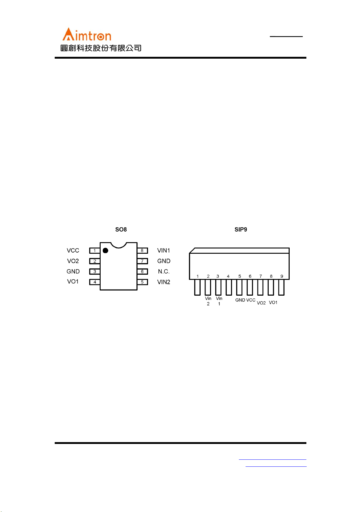
Pin Configuration
Description
The AT5608 is a monolithic integrated circuit
designed for driving bi-directional DC motor.
It has two pins of logic input for controlling the
forward/reverse and braking,
output current of up to 100mA (typical)
according to the logic control.
which can supply an
Applications
DVD and VCD player tray driver.
2F, No.10, Prosperity RD. II, Science-Based Industrial Park, Hsinchu 300,Taiwan, R.O.C.
Tel: 886-3-563-0878 WWW: http://www.aimtron.com.tw
Fax: 886-3-563-0879 Email: service@aimtron.com.tw
1
AT5608
Bi-directional Motor Driver
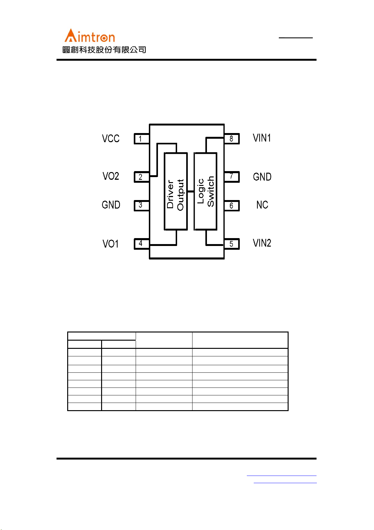
Circuit Configuration
Pin Descriptions
Pin No.
SO8 SIP9
1 6 VCC Power supply
2
35 GNDGND
4 8 VO1 Motor output1
5 2 VIN2 Logic input2
6 1,4,9 N.C. N.C.
75 GNDGND
8 3 VIN1 Logic input1
2F, No.10, Prosperity RD. II, Science-Based Industrial Park, Hsinchu 300,Taiwan, R.O.C.
Tel: 886-3-563-0878 WWW: http://www.aimtron.com.tw
Fax: 886-3-563-0879 Email: service@aimtron.com.tw
7
Pin name Function
VO2
Motor output2
2
AT5608
Bi-directional Motor Driver
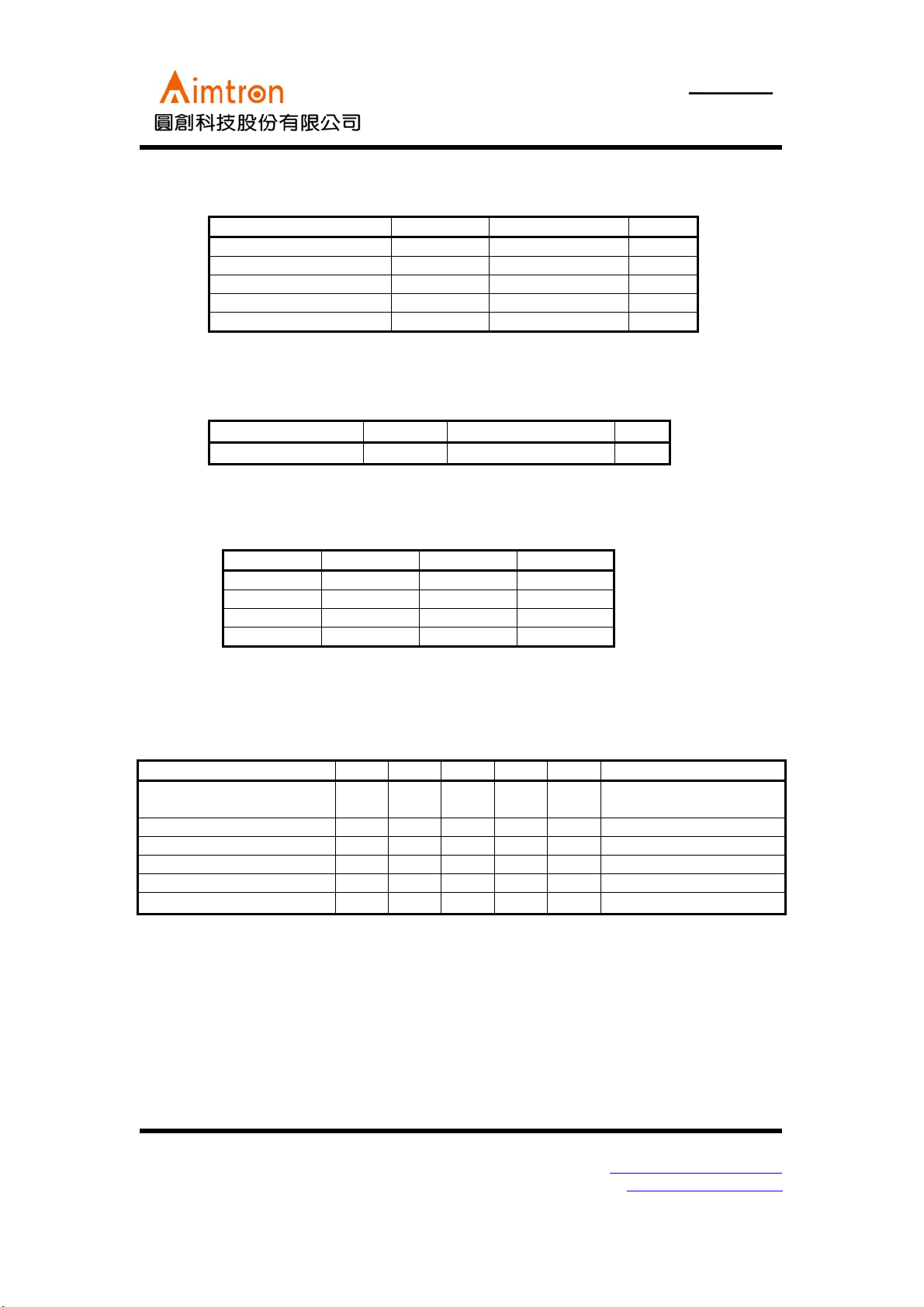
Absolute maximum ratings (Ta = 25oC)
Parameter Symbol Limits unit
Power supply voltage V
Power dissipation P
Operating temperature T
Storage temperature T
Maximum output current I
﹡Reduce by 13.5 mW for each increase in T
CC
d
opr
stg
OUT
of 1oC over 25oC.
a
Recommended operating conditions (Ta = 25oC)
Parameter Symbol Limits unit
Power supply voltage Vcc 4.5~12 V
13.5 V
*
450
-20~+60
-55~+125
500 mA
mW
o
C
o
C
Input truth table
VIN1(8pin) VIN2(5pin) VO1(4pin) VO2(2pin)
HLHL
LHLH
HHL L
L L OPEN OPEN
*:HIGH level input is 2.0V or more
LOW level input is 0.8V or less.
Electrical characteristics (unless otherwise noted, Ta = 25
Parameter Symbol Min. Typ. Max. Unit Conditions
Standby supply current I
Output current I
Output saturation voltage V
Input high level voltage V
Input high level voltage V
Input high level current I
A diode that absorbs at least 500 mA is built in to give protection against surge currents with a pulse width of 10 ms and a duty
ratio of 10﹪or less.
ST
O
CE
IH
IL
IH
- - 0.4 mA When inputs VIN1 and
200 - - mA
--1.7VI
2.0 - - V
--0.8V
--400μAVIH=4.5V
o
C and V
= 9V)
CC
VIN2 are both "L" level
=100mA
O
2F, No.10, Prosperity RD. II, Science-Based Industrial Park, Hsinchu 300,Taiwan, R.O.C.
Tel: 886-3-563-0878 WWW: http://www.aimtron.com.tw
Fax: 886-3-563-0879 Email: service@aimtron.com.tw
3
 Loading...