

AIM AT5558S, AT5558D Datasheet
AT5558
Quad Operational Amplifier for Audio
2F, No.10, Prosperity RD. II, Science-Based Industrial Park, Hsinchu 300,Taiwan, R.O.C.
Tel: 886-3-563-0878 WWW: http://www.aimtron.com.tw
Fax: 886-3-563-0879 Email: service@aimtron.com.tw
1
Features
˙Operating Voltage : ±1.5~±8V or 3~16V
˙Large DC Voltage Gain: 100 dB
˙High input Resistance :0.8MΩ
˙Low Input Offset Voltage:0.7mV
˙Bandwidth(unity gain):3MHz
˙Bipolar Technology
Description
The AT5558 consists of four independent, high
gain, internally compensated amplifiers which
were designed specifically to operate from a
single or split power supply.
Application areas include transducer amplifier,
DC gain blocks and all the conventional
operational amplifier circuits. The AT5558 can
be directly operated +5V power supply, which is
normally used in digital systems.
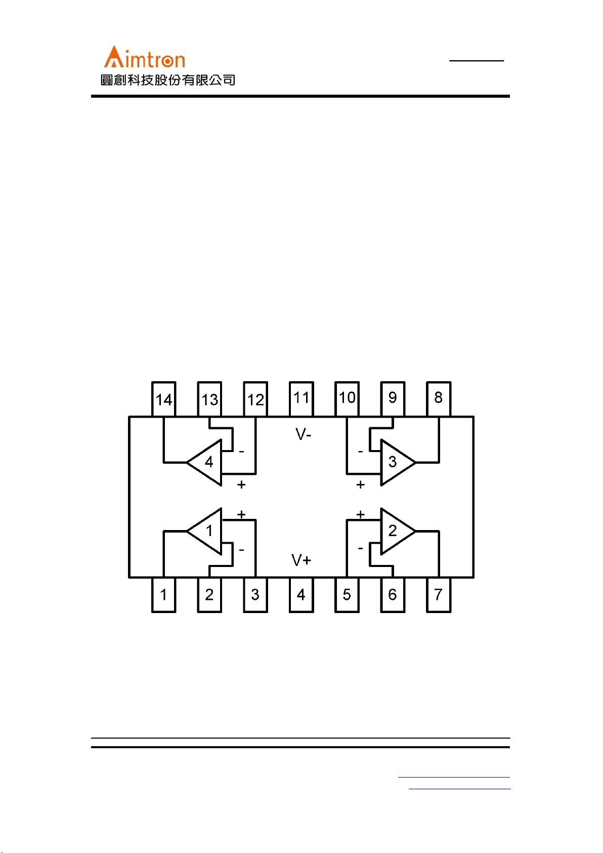
Block Diagram
AT5558
Quad Operational Amplifier for Audio
2F, No.10, Prosperity RD. II, Science-Based Industrial Park, Hsinchu 300,Taiwan, R.O.C.
Tel: 886-3-563-0878 WWW: http://www.aimtron.com.tw
Fax: 886-3-563-0879 Email: service@aimtron.com.tw
2
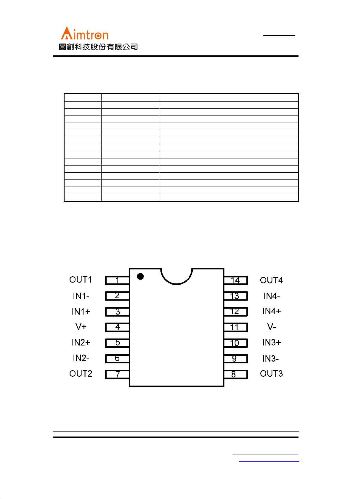
Pin Descriptions
Pin No.
Pin name Function
1 OUT1 Output 1
2 IN1- Negative input 1
3 IN1+ Positive input 1
4 V+ Positive Power Supply
5 IN2+ Positive input 2
6 IN2- Negative input 2
7 OUT2 Output 2
8 OUT3 Output 3
9 IN3- Negative input 3
10 IN3+ Positive input 3
11 V- Negative Power Supply
12 IN4+ Positive input 4
13 IN4- Negative input 4
14 OUT4 Output 4
PinOut
AT5558
Quad Operational Amplifier for Audio
2F, No.10, Prosperity RD. II, Science-Based Industrial Park, Hsinchu 300,Taiwan, R.O.C.
Tel: 886-3-563-0878 WWW: http://www.aimtron.com.tw
Fax: 886-3-563-0879 Email: service@aimtron.com.tw
3
Absolute maximum ratings (Ta = 25oC)
Parameter Symbol Limits unit
Power supply voltage V+/V-
±8
V
Diffeential Input Voltage V
ID
±14
V
Input Voltage V
IN
±7
Power Dissipation P
D
500 mW
Operating temperature T
opr
0~+85
o
C
Storage temperature T
stg
-55~+150
o
C
*Stresses beyond those listed under “ absolute maximum ratings” may cause
permanent damage to the device. Exposure to absolute-maximum-rated conditions
for extended peeriods may affect device reliability.
Recommended Operating Condition
Parameter Symbol Limits unit
Power supply voltage V+/V-
±1.5~±8(3~16)
V
Electrical characteristics (
unless otherwise noted, Ta = 25oC, V+ = 6V, V- =-6V
)
Parameter Symbol Min. Typ. Max. Unit Conditions
Input Offset Voltage V
IO
-0.7 - mV
Rs≤10KΩ
Input Offset Current I
IO
-5200 nA
Input Bias Current I
B
-70500 nA
Input Resistance R
IN
0.5 0.8 -
mΩ
Input Voltage Range Vin - -
±5
V
Large Signal Voltage Gain Av - 100 - dB
Gain Bandwidth GBW - 3 - MHz
Phase Margin
θm
-60 - deg.
Output Voltage Swing Vsw - +5.09/
-4.86
-V
RL=10KΩ
DC common mode
Rejection ratio
CMRR - 98 - dB
Power supply rejection
Ratio
PSRR - 95 - dB
Slew rate SR 1.0 1.3 -
V/μS
RL=2KΩ
CL
=100pF
Input Noise Voltage Vnoise - 1.94 - uVrms
Output Resistance Ro - 75 -
Ω
Output Short-Circuit
Current
Ios - 100 - mA *
Channel separation
α
- 100 - dB f=1KHz~20KHz
Rise Time Tr - 55 - ns
Operating Current Icc - 5.5 10 mA
*1 Due to power disspation issue, it is not allowed for both channels to operate at this condition at the same moment.
AT5558
Quad Operational Amplifier for Audio
2F, No.10, Prosperity RD. II, Science-Based Industrial Park, Hsinchu 300,Taiwan, R.O.C.
Tel: 886-3-563-0878 WWW: http://www.aimtron.com.tw
Fax: 886-3-563-0879 Email: service@aimtron.com.tw
4
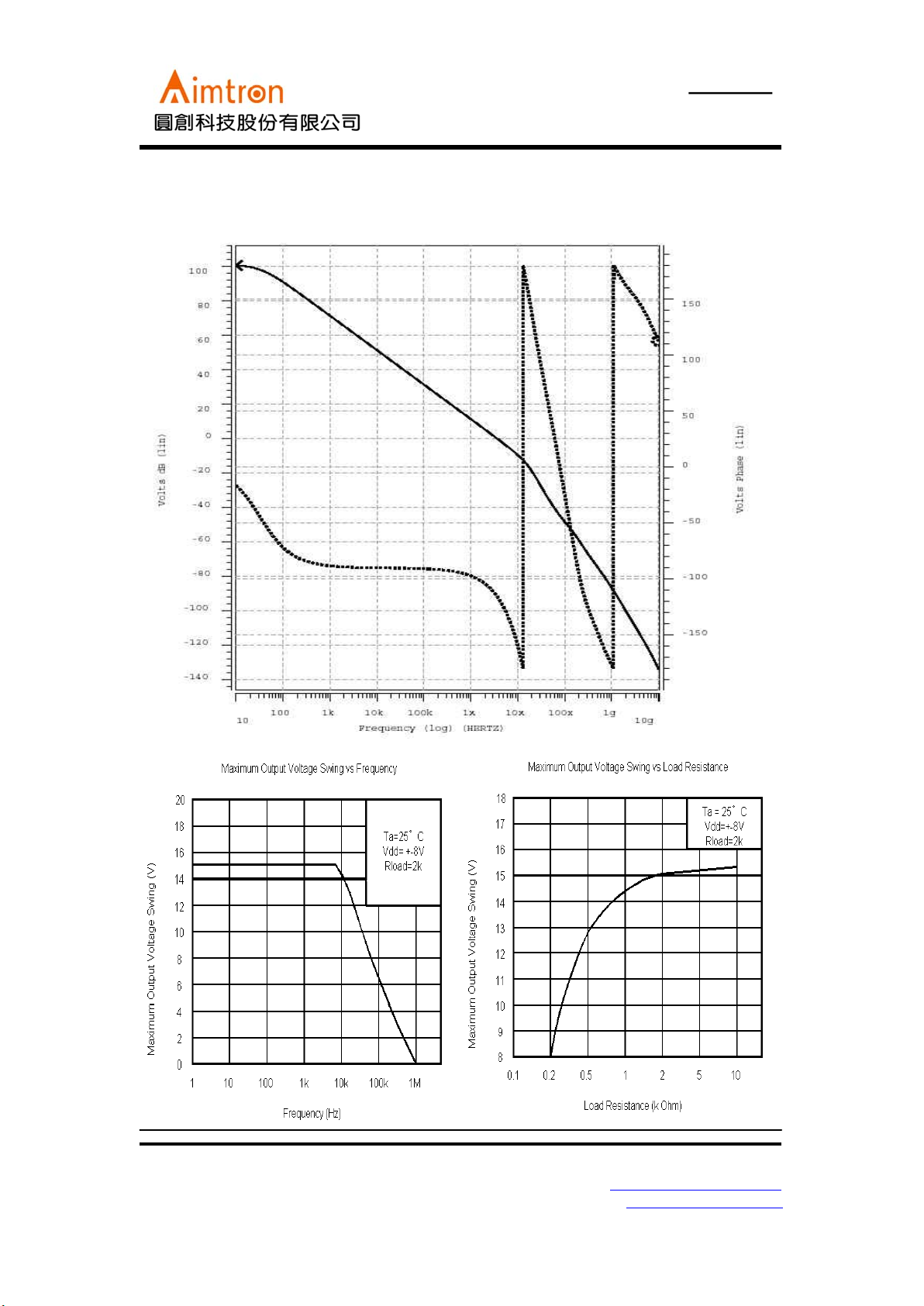
Typical Curve
Open-Loop Gain Bandwidth and Phase Margin
 Loading...