

Page 1
PF3000 and PF3000 Pro – Application Rate Mode - Quick Reference Menu Tree for Mid-Tech controllers with Data-Link– March 2002
p
b
f
p
p
p
p
p
p
p
p
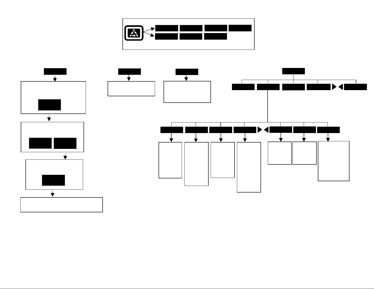
FIELD
[Create or change field and name field
functions. Active configuration for
field displayed.]
VIEW
CONFIG
[Set active configuration and active
tgt prescription file.]
ACTIVE
ON/OFF
[Select and accept new tgt
rescription file.]
EDIT
TGT FILE
VIEW
INFO
[Create or change load and
name load functions.]
Menu Key
FIELD LOAD
CAL SETUP
Press Menu Key to switch between Main Menu keys
LOAD
Press at
guidance
reference
SHOW MAP
[Splits screen and shows On
Screen Map on left side.
Press HIDE MAP key to
return to full screen. ]
SET A
eginning o
ass.
SET B
Press at end
of guidance
reference
ass. When
using curve
attern,
ress at end
of every
ass.
DIAG
RESET
Press to
reset
guidance
and area
oints to
start a new
field.
OPTIONS SHOW MAP
PAUSE
Press to
guidance
when filling
applicator.
Drive back
to swath and
RESUME
key.
ause
ress
LIGHTBARMARKS
OPTIONS
NAVIGATE
ADD/STRT
Used for
Headlands.
See Lightbar
Manual.
BOUNDARY
CLR/STOP
Used for
Headlands.
See Lightbar
Manual.
GRID
AREA PT
Press at every
corner of field to
calculate field
area. Must have
“Field Area”
displayed on
main screen to
see area.
[Screen displays field, product, units/ac and default
rate stored in tgt file.]
Revision 2 1 of 4 P.N. 2002831-18
Page 2
PF3000 and PF3000 Pro – Application Rate Mode - Quick Reference Menu Tree for Mid-Tech controllers with Data-Link– March 2002
p
N
g
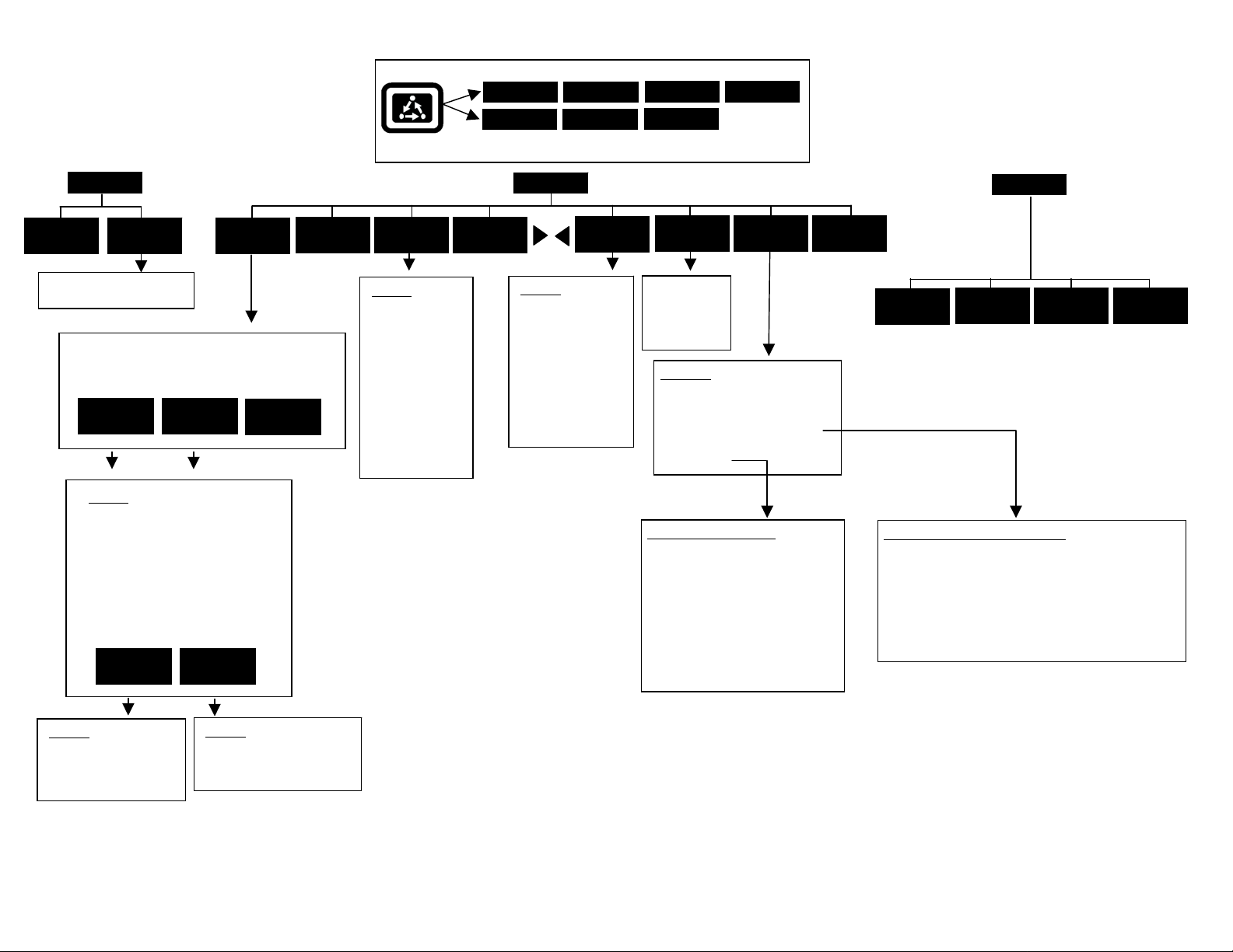
Menu Key
FIELD LOAD
OPTIONS SHOW MAP
CAL
AREA
DISTANCE
[Radar calibration screen]
[Screen Displays all product/controller
configurations]
EDIT
SETTINGS
CREATE
NEW
Settings
Controller Make
Controller Model
Product
Units
Ground Speed Source
App Distance From GPS
Full Swath
Tgt Units:Contrler Units
Target Rate Increment
Actual Rate Scale Factor
ADVANCED
SETTINGS
CONTRLER
SETTINGS
APP RATE
CONFIG
DELETE
MARKS
CAL SETUP
Press Menu Key to switch between Main Menu keys
SETUP
CARD
Settings
Logging device
Logging interval
Log file
[To erase files,
ress SHOW
ALL FILES key,
select file, press
FILE OPTIONS
key and press
LOAD
CONSOLE
Settings
Operating mode
Units of Measure
Month/Day/Year
Time
Serial number
Box cal
Voltage cal
GPS check sum
Field marker input
Display brightness
ERASE FILE
key.]
DIAG
MEMORY
[Clear data in
loads or erase
all fields
functions]
Selections
MEA MESSAGE
GPS/PORT CONFIGURATION
BEACON DIFFERENTIAL
SATELLITE DIFFERENTIAL
LIGHTBAR
GUIDANCE
Guidance Screen Settings
Pattern
Headland Type
Look-Ahead
Display Mode
Swath Direction
Swath Width
Antenna Offset
Pass Skips
Units Displayed
Contour Log Interval
GPS
MAP
DIAG
SYSTEM
SENSORS
GPS
RAW
NMEA
Satellite Differential Screen Settings
Differential source = BEACON or WAAS or SATELLITE
Differential provider
Satellite frequency
Satellite baud rate
Provider user code
Omnistar code
Subscription expiration
Age of differential
Settings
Target rate outside field
Controller time delay
Settings
Controller Channel
Controller Operating Mode
Actual rate units
Lo
actual rate
Revision 2 2 of 4 P.N. 2002831-18
Page 3

PF3000 and PF3000 Pro – Quick Reference Setup Instructions for all Mid-Tech controllers with Data-Link – March 2002
Note: These instructions pertain to PF firmware versions 4.00 or
higher. Cable Connections: Connect the serial cable from the
DataLink to Port3 of the PF.
Settings for MidTech TASC/Ag Logix Controllers that have DataLink
1. Press SETUP key. Press APP RATE CONFIG key. Press CREATE
NEW key. Set the following:
Controller Make: Set to MIDTECH.
Controller Model: Set to your MidTech model.
Product: Press EDIT key. You can select an existing product and press
ACCEPT key or create a new product by pressing CREATE NEW key.
Press EDIT NAME key and enter name of product. Use Left or Right
Arrow keys to select a character. Use Up or Down Arrow key to change
the character. Set every character and press ACCEPT key twice.
Units: Usually set to GALLONS. Set to Units/Acre of application.
Ground Speed Sensor: Set to RADAR or GPS or SERIAL. SERIAL is
recommended. Note: This setting affects all configurations.
App Distance From GPS: Set to distance between where product exits
applicator and position of GPS antenna on vehicle. Example: If spray
boom is 20 feet behind GPS antenna set to 20 ft back.
Full Swath: Ignore setting. Swath comes from serial port of MidTech.
Tgt Units:Contrler Units: Normally set to 1:1.0000. This ratio is used to
convert the units in a target file (.tgt) to the units of application.
Example: Tgt file in pints/ac of Treflan, MidTech applies gallons/ac. If
tank mix is 1 pint of Treflan / 10 gallon water, then set to 1:10.0000.
Target Rate Increment: Determines increment value by which you can
change the manual target rate with each press of Up or Down arrow keys.
Actual Rate Scale Factor: Use chart below for setting.
Avg. Speed Swath Application Rate between
0-25 mph 0-80 ft 0-10 units/ac
0-10 mph 0-80 ft 11-100 units/ac
11-15 mph 0-50 ft 11-100 units/ac
11-15 mph 51-80 ft 11-100 units/ac
16-25 mph 0-80 ft 11-100 units/ac
0-25 mph 0-80 ft 101-500 units/ac
0-10 mph 0-80 ft 501-1000 units/ac
11-15 mph 0-50 ft 501-1000 units/ac
11-15 mph 51-80 ft 501-1000 units/ac
16-25 mph 0-80 ft 501-1000 units/ac
0-25 mph 0-80 ft 1001+ units/ac
Scale Factor
1.000
1.000
1.000
0.100
0.100
0.100
0.100
0.100
0.010
0.010
0.010
When the data is mapped, the rate will be 1/10th of the real rate when the
Actual Rate Scale Factor is 0.100. It will be 1/100
th
of the real rate when
the Actual Rate Scale Factor is 0.010. The rate actually applied and rate
that appears on Pro is unaffected by this setting.
2. Press CONTRLER SETTINGS key. Set the following:
Controller Channel: Set to channel of MidTech to record or control rate.
Note: If you have an Ag Logix, TASC6000 or TASC6100 this setting will not be displayed.
Controller Operating Mode:
Set to Granular for all TASC models.
Set to Granular or Liquid if using Ag Logix model.
Note: To view mode of Ag Logix, move dial to “Total Applied” hold
switch to “-“ position. If “L” set to Liquid. If “Gr” set to Granular.
Note: If you have a TASC 6000, 6300, 6600 this setting will not appear.
3 Press EXIT key to return to screen with ADVANCED SETTINGS key on
bottom. Press the ADVANCED SETTINGS key.
Target Rate Outside Field: This only pertains to using a target file.
Set to ZERO if want rate outside field to be zero.
Set to USE LAST if want rate to be the last rate used at the time the
vehicle is detected outside the field. This is useful when experiencing
problems with the vehicle being falsely detected outside of the field
during the outside pass.
Set to TGT DEFAULT if want rate outside field to be the default rate
stored in the target rate file.
Controller Time Delay: Set to 3 seconds. This is delay of controller to
change application equipment to new rate + 2 seconds.
Actual Rate Units: Ignore this setting.
Log Actual Rate: Set to YES to log actual rate to card. Set to NO,
otherwise.
4 Exit back to main screen.
a)Press FIELD key twice.
b)Select appropriate field and press VIEW CONFIG key.
c)Select appropriate product/controller configuration and press ACTIVE
ON/OFF key to check it as active.(All other configs must be unchecked
first).
d)If you will be using a target file, press EDIT TGT FILE key, otherwise
press EXIT key and skip to step f.
e)Select target file. Press VIEW INFO key to ensure it is the correct one.
After exiting view info screen, press ACCEPT key. Press EXIT key.
f)Press ACCEPT key to accept field.
Revision 2 3 of 4 P.N. 2002831-18
Page 4

PF3000 and PF3000 Pro – Quick Reference Setup Instructions for all Mid-Tech controllers with Data-Link – March 2002
Note: The Datalink must be set to “External Enable” for the PF to establish
communication with controller. Channel switch on Mid-Tech, must be in the
“Alt-Rate” position for PF to send target rate to controller. If you do not want
PF to control target rate, but want it to record the actual rate from a channel, set
the channel switch on Mid-Tech to “ON” or “Standard” (exception: on Ag
Logix, PF can not receive actual rate without controlling target rate).
How to change a setting
Press the EDIT key and use the Up or Down Arrow keys to change the setting.
For most settings, you can set each digit by pressing the Left or Right Arrow
key to select the digit. Use the Up or Down Arrow keys to set the digit.
Setting the Target Rate
1 The display item “Target Rate” must be displayed on the main screen to
set the rate.
Arrow symbols on the line displaying target rate indicate that this display
item is selected for changing. Press the key to the right of the line
displaying target rate if you do not see these arrows. Press it again to
deselect the line (remove the box) but keep the arrow symbols.
2 You can either set a manual rate or use a target file to automatically
control the rate based on the vehicle position in the field.
Setting a manual rate
a) Press Right Arrow key to highlight “man” (“m” if viewing on screen
map).
b) Use the Up or Down Arrow keys to set the manual rate.
c) If you want to change how much the rate changes with each arrow
press refer to step 1 on other side of sheet and edit the “Target Rate
Increment” setting.
Using a target file and setting an automatic rate
a) Press Left Arrow key to highlight “auto” (“a” if viewing on screen
map).
b) You must have a target file (.tgt) selected for the field, otherwise the
PF will not control the rate of the Raven. Refer to step 4 on other side
on how to set the Target File.
You can switch between auto and man whenever you are on the main
screen and Target Rate is selected for changing.
Setting the PF to NOT control the rate (record rate only)
Set the Target Rate to “auto” and leave the Target File setting on
“NONE”.
Area Counting
The area count switch (located on bottom right of front panel) must be up and
MidTech must start applying for area to be on.
Revision 2 4 of 4 P.N. 2002831-18
 Loading...