

Page 1
Product Bulletin
Release Date: April 2002
Instructions for Initial Startup of Ag Leader Lightbar
Beginning April 1, 2002, the instructions for initial startup of the Ag Leader Lightbar
have changed slightly. These changes apply to all Lightbars with the model number of
21A that are used in conjunction with an PF Series monitor (PF3000, PF3000 PRO and
PFavantage) running version 4.20 and lower. This model number can be found on the
serial number tag on the bottom the Lightbar and should read AgGPS 21A Lightbar.
If the Ag Leader Lightbar does not have this model number, this product bulletin can be
disregarded and the instructions detailed in the Lightbar Manual should be followed as
usual.
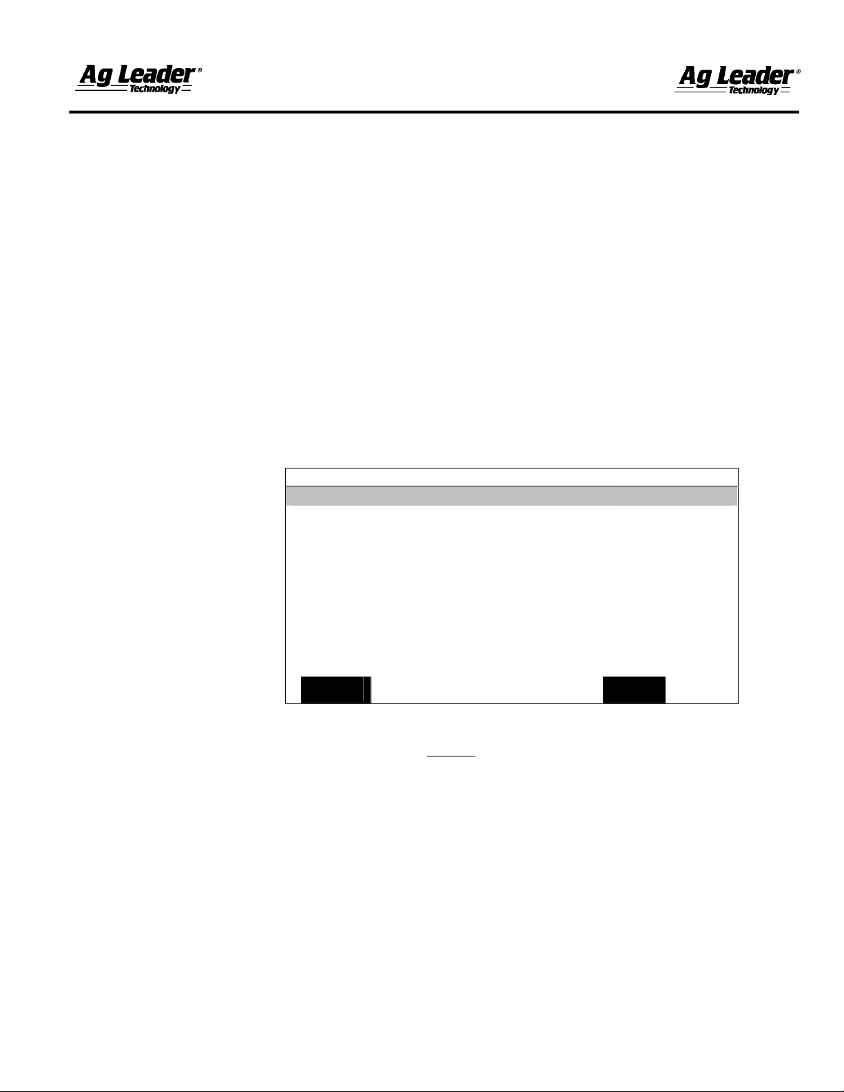
1. Before hooking the Lightbar to the GPS unit, the Lightbar Status setting must be
turned ON in the PF monitor. To turn on the Lightbar, press the MENU button until
you see SETUP on the bottom of the screen and press this button. Locate and press
the GPS button (may need to scroll left or right) on the bottom of the screen. A
screen similar to the one pictured below should now be displayed.
GPS/LIGHTBAR
Lightbar Status ON
Mounting Position Dash
Brightness (1-5) 5
Text Mode PASS # & ERROR
Proximity Sensitivity 25 ft
LED Spacing Mode LINEAR
LED Spacing 1.0 ft
End Distance --- ft
2. Lightbar status should now be highlighted. Press the EDIT button and use the up or
down arrow to change this setting to ON (Do Not
time).
3. Now plug the Lightbar into the GPS connection.
4. After plugging in the Lightbar, press ACCEPT on the PF monitor. The Lightbar
should now be ready for operation. Refer to the Lightbar Manual for additional setup
and operational instructions.
If you see EZ-Guide displayed on the Lightbar or it prompts you for a swath width, the
process was not completed correctly and should be tried again. It is important to plug the
Lightbar in first, before you press the Accept button. If you still encounter problems,
please contact your local Ag Leader dealer or our Tech Support department at (515) 2325363 ext. 1.
EDIT
EXIT
press the ACCEPT button at this
February 2003
Page 2

Page 3

Light Bar
INSTALLATION
AND
GENERAL INSTRUCTIONS
February 2003 Rev.3 3000135
Page 4

Page 5

Light Bar
Ag Leader Technology
Important Notices
Before beginning installation of your Light Bar, please take the time to
thoroughly read these instructions. Signal words (CAUTION,
IMPORTANT, and NOTE) are provided to draw attention to
information that is important for the safe/correct installation and
operation of this product.
• CAUTION--will alert you to situations that will impact the physical
safety of you or others.
• IMPORTANT—will alert you to the potential for damage to the
product or loss of data.
• NOTE--will provide you with additional information to simplify a
procedure or clarify a process.
After completing installation of the Light Bar we recommend that you
place these instructions in the Options Section of your PF monitor
Operator’s Manual to prevent their loss.
To receive upgrade/update information of this product you must send
in or fax the Registration Form. Refer to the Registration Form for
address and fax number.
Installing Light Bar 2
General Information 5
Explanation of GPS/Light Bar Screen 5
Explanation of GPS/Guidance Screen 8
General Operation 13
Following a Curved Line 13
Using Headlands 13
Using Light Bar with PF Series monitors 13
PF monitor Setup for Light Bar 31
PF monitor Pro Setup for Guidance 40
Parts List 51
Contents
Item Page
***
February 2003 Rev.3 3000135
1
Page 6

Installation
Installing Light
Bar
Light Bar
Ag Leader Technology
IMPORTANT: The Light Bar must be mounted inside the cab
of your vehicle. The Light Bar is not resistant to weather
elements on the outside of the vehicle and could be damaged if
mounted outside of the cab.
1. Determine a location on the dash or ceiling to mount the Light Bar.
The Light Bar should be positioned within your peripheral vision.
2. Use an upright position for dash mounting and inverted for ceiling
mounting.
NOTE: Mounting the Light Bar on the ceiling inverts the Light Bar
text and requires a SETUP change.
3. Mounting the Light Bar bracket may be done by using three
methods: Dual-Lock strips, mounting hardware or the Optional
Suction cup. Select one of the methods below to mount the
bracket.
a. Bracket mounting with Dual-Lock strips:
(1) Clean the surface of the mounting location with
provided alcohol swabs.
(2) Remove the peel off strip from the Dual-Lock strip
on the back of the Light Bar bracket.
Do not touch the adhesive surface of the strip.
(3) Press the Light Bar bracket to the mounting location
determined in Step 1. Press the bracket firmly or
gently pound on the bracket to bond the adhesive
strip.
NOTE: The two additional Dual-Lock strips are for
replacement of the bracket strip or to add additional
mounting locations in the cab.
b. Bracket mounting with hardware:
(1) Using the mounting bracket as a template, mark the
three bracket holes for the position you determined
in Step 1.
(2) Use a 3/16-in. drill bit to drill the holes.
2
February 2003 Rev.3 3000135
Page 7
Light Bar
Ag Leader Technology
NOTE: Use the screws, nuts and washers for plastic or
soft materials or self-tapping screws for sheet metal.
Refer to diagram in hardware bag.
4. Attach Light Bar to bracket.
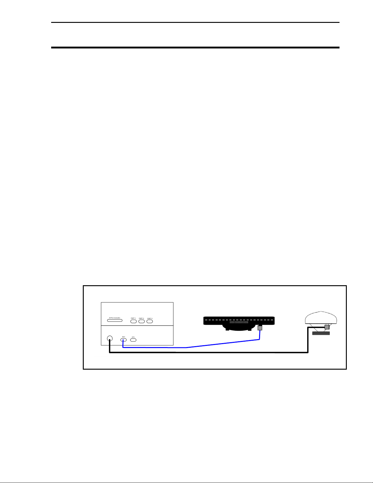
5. Attach cable to Light Bar and run to the AUX port of the Add-On
GPS3050 or 3100.
NOTE: If you are attaching the Light Bar to a PF3000 Pro or PFadvantage, attach the Light Bar cable to the AUX 1 port.
Figure 1. Light Bar cable connections to PF3000 with Add-On GPS
Installation
(3) Attach bracket with screws, nuts and washers
provided.
c. Bracket Mounting with optional suction cup:
NOTE: The Optional Suction cup is ordered
separately from the Lightbar Kit.
(1) Attach suction cup to bracket with 1/4 inch nut
(NOT provided).
(2) Refer to suction cup instructions to mount.
Ferbruary 2003 Rev.3 3000135
3
Page 8
Installation
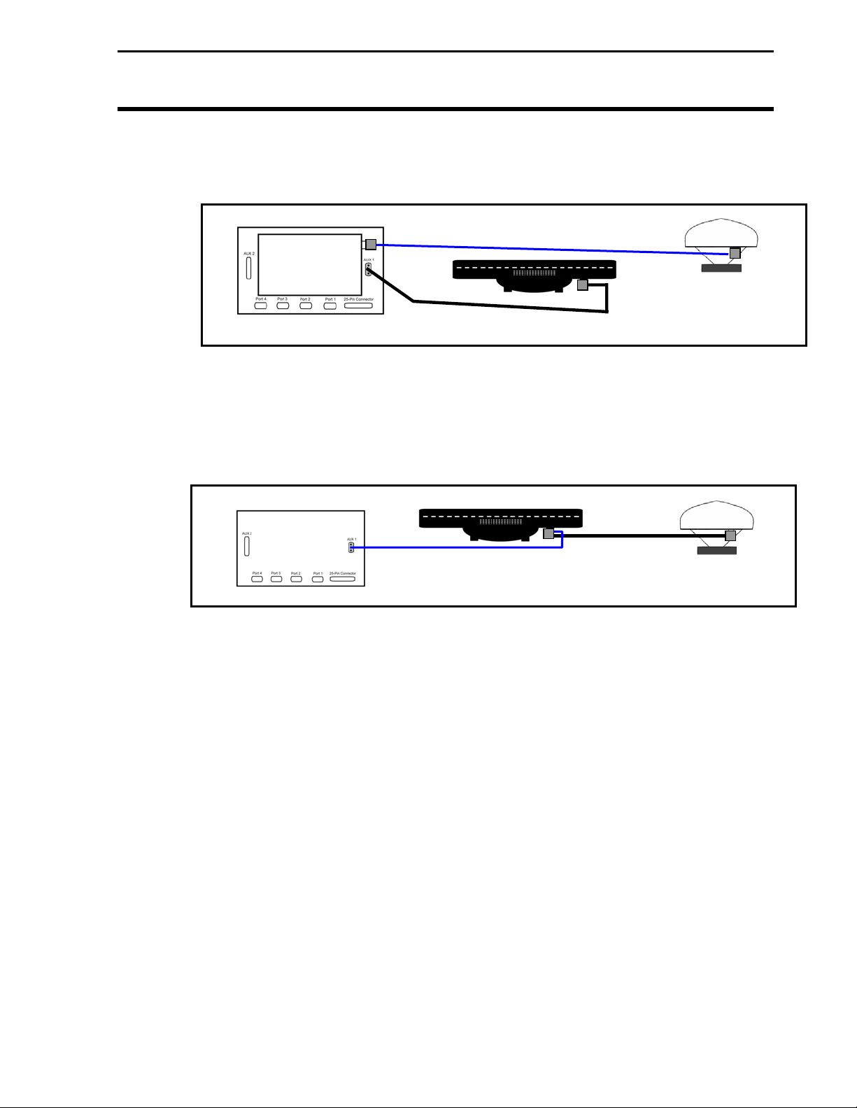
Figure 3. Light Bar cable connections to PF3000 Pro or PFadvantage with “all-
Light Bar
Ag Leader Technology
Figure 2. Light Bar cable connections to PF3000 Pro with integrated GPS
in-the-antenna” GPS 4100
4
February 2003 Rev.3 3000135
Page 9
Light Bar
Ag Leader Technology
General
Information
Explanation of
GPS/Lightbar
Screen
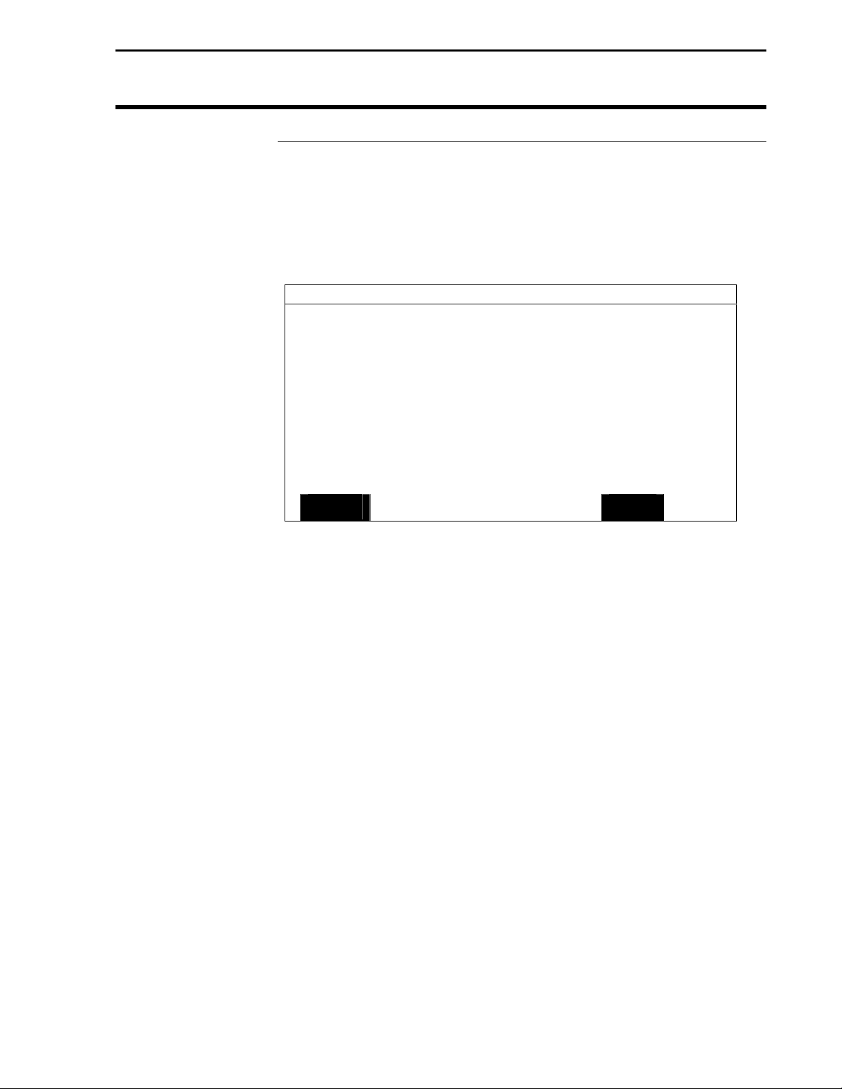
Use the following information to determine your requirements to setup the PF Series monitor for your Light Bar.
NOTE: The Add-On GPS3050/3100, or GPS 4100 are the only
receivers that can operate the Ag Leader Light Bar.
GPS/LIGHTBAR
Lightbar Status ON
Mounting Position Dash
Brightness (1-5) 5
Text Mode PASS # & ERROR
Proximity Sensitivity 25 ft
LED Spacing Mode LINEAR
LED Spacing 1.0 ft
End Distance --- ft
EDIT
Use Figure 4 to note the location of items on the screen.
NOTE: The Light Bar may be used in GRAIN HARVEST,
APPLICATION RATE or SITE VERIFICATION modes. Refer to
Console Setup in the Setup Section of the PF monitor Operators
Manual.
Lightbar Status: ON signifies that power is being sent to the light
bar.
Mounting Position: Ceiling mounting of the lightbar requires that it
be inverted. This setting will allow the text to be inverted also.
Brightness (1-5): This setting (1 = dim, 5 = bright) allows you to
determine the brightness of the LED on the lightbar.
Figure 4
General Information
EXIT
February 2003 Rev.3 3000135
5
Page 10
General Information
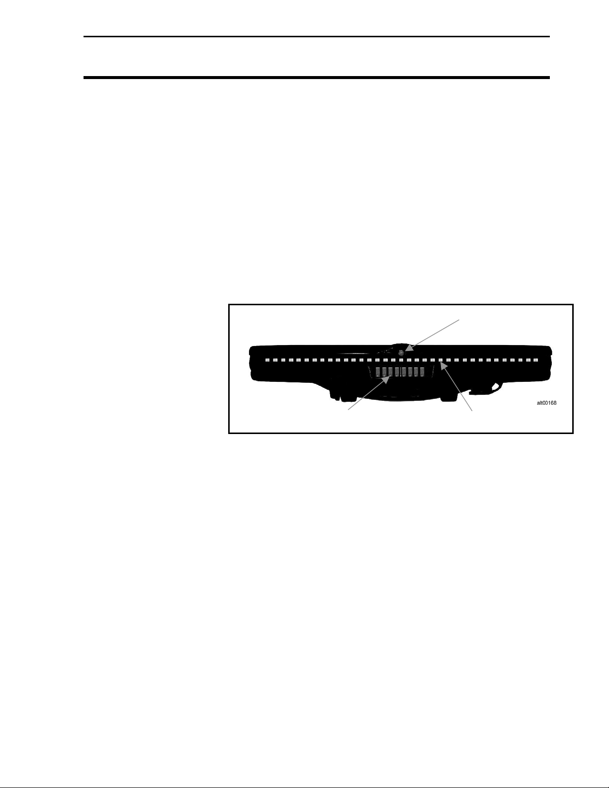
Text Mode: Provides the following selection to monitor (See
Figure 2 for location of text items)
Pass # & Error - Provides the pass number and error
from the center of the swath.
No Text – No text is displayed on the screen
Demo – Used for demonstration only, cycles power on
and off
Pass & Speed – Provides pass number and ground speed
Ground Speed – Displays ground speed only
Light Bar
Ag Leader Technology
Approach LED
Text Display Area
Guidance LED
Figure 5
Heading Error – Displays the degree error for the
heading from the center of the swath
Cross – TRK Error – Displays the error between current
position and swath
True Heading – Displays the actual degree heading from True
North
End Line Dist(ance) – Displays the distance from the
end of a pass (decreasing)
Start Line Dist(ance) – Displays the distance from the
start of a pass (increasing)
6
February 2003 Rev.3 3000135
Page 11

Light Bar
Ag Leader Technology
and magnitude of the correction, more
arrows indicate a sharper turn. For
curved modes only.
Sensitivity: This setting sets the sensitivity for the PAUSE function.
It only affects the large center LED of the Light Bar.
The large LED changes color as you approach headlands,
or the Pause/Resume point.
NOTE: LED sensitivity should be set larger as
ground speed increases
LED Spacing Mode: Use the Linear or Scaled settings to set the
spacing interval of the lightbar LED’s.
line. i.e. a setting of one foot off line from the
center of the swath will be represented by one
LED. The second LED will represent two feet
etc.
Scaled – Sets the first 10 LED’s each side of the
lightbar on a linear scale. The outer 7 LED’s on
each side are scaled to represent an end value
setting.
LED Spacing: This setting establishes LED spacing distance. If the
setting is 3 feet, the LED slides one unit to the left or
right for every 3 feet off line.
NOTE: The smaller the LED spacing the more precise
guidance the lightbar will provide.
End Distance: This setting is used when in Scaled for LED Spacing
Mode. You cannot set an end value smaller than the
LED spacing multiplied by 17 (there are 17 LEDs on
each side of the lightbar.
General Information
Pass # - Displays the current pass number for that field
Curve Arrows – Displays arrows indicating the direction
GPS Status – Displays GPS and Differential information on the text screen
Linear - Set the light bar to show off-line distance on a
February 2003 Rev.3 3000135
7
Page 12
General Information
Explanation of
GPS/Guidance
Screen
Use Figure 6 to note the location of items on the screen.
NOTE: The Light Bar may be used in GRAIN HARVEST,
APPLICATION RATE or SITE VERIFICATION modes. Refer to
Console Setup in the Setup Section of the PF monitor Operator’s
Manual.
Pattern: Determines which guidance pattern is driven.
None: Configures straight line guidance parallel to the
beginning and end of the first swath driven.
Curve Spiral: Use this curve setting to drive spirals or
closed rings.
Curve: Activates last curve following. Positions are
logged during current swath. The next swath is
parallel to the previous swath driven.
Skip Pass: Provides parallel guidance in a racetrack pattern
with a user specified swath skip. This setting is
for equipment with a large turn radius.
A+ Heading: Allows establishing a reference line from True North
Light Bar
Ag Leader Technology
GPS/GUIDANCE
Pattern NONE
Headland Type CURVED
Look – Ahead 3 SEC
Display Mode SHOW CORRECTION
Swath Direction Auto
Swath Width 60.0 ft
Antenna Offset +20.0 ft
Pass Skips 2
Units Displayed English
Contour Log Interval SWATH CHANGE
EDIT
Figure 6
EXIT
8
February 2003 Rev.3 3000135
Page 13

Light Bar
Ag Leader Technology
Headland Type: Determines the type of headland used.
None: In this mode, swath lengths are
infinite. The center LED remains one color,
never changing to indicate end of swath.
C-Clamp: Field ends are sprayed as headlands so
parallel passes may be used with minimal
overlap.
Curved: Logs irregular boundary shapes for
guidance.
Closed: Defines headlands with a series of user
entered points. The last point connects to
the first point to form a closed loop.
A-B End Zones: A & B points mark the center of
the boundary swath. (See Figure
Look-Ahead: The value that allows the system to predict future error.
This accounts for system delays, including operator
response time. 3 seconds is the default setting.
Display Mode: Determines which direction from the center of the
light bar the LEDs light indicate off-line error.
Show Error: Displays the extent and direction of the
error between current position and
swath line. Steer vehicle to "pull"
lights back to center of the lightbar.
Show Correction: Displays the extent and direction
of the necessary correction to
match the swath line. Steer
vehicle by "chasing" lights left or
right.
Swath Direction: This setting determines whether the swath is
manually or automatically incremented.
General Information
4) When the system is inside the
boundary area the center LED
illuminates green. The center
LED glows red when beyond the
boundary area.
February 2003 Rev.3 3000135
9
Page 14

General Information
Auto: Automatically increments in the direction
turned after the first swath. The swath
increments when the vehicle turns more than
110 degrees.
Right: Swaths are manually incremented to the
right of the A-B line.
Left: Swaths are manually incremented to the left
of the A-B line.
Snap: Automatically increments swath
number to the closest swath. (Not availabe
with Pass Skip and Curve following.) This is
the default setting.
Swath Width: Adjust in .5 ft increments from 1 to 999 ft. Set the
swath width to 1 ft less than the actual swath width to
reduce skip. Set the swath width 1 ft more than the
actual swath to reduce overlap.
Antenna Offset: The distance from the antenna, ahead or behind the
spray boom so that guidance information is
referenced to the spraying boom instead of the
antenna. It is adjusted in .5 ft increments from 0 to
100 ft. The antenna must be placed along the
vehicle’s centerline. Negative numbers are used for
a boom in front of the antenna, positive numbers are
for a boom behind the antenna.
Pass Skips: Adjusted in 0 to 99.
Units Displayed: Determines whether Metric or US Standards
(English) are used. The default is Metric.
Contour Log Interval: The settings are Swath Change and Heading
Change. Heading change is the default and
recommended setting. With the Contour Log
Interval set to Heading Change a reference
point will be logged whenever the heading
changes slightly.
Light Bar
Ag Leader Technology
10
February 2003 Rev.3 3000135
Page 15
Light Bar
Ag Leader Technology
Approach LED
Action
Figure 7. Headland Approach LED Action for AB ENDZONE
Green
Figures 7 through 9 show the action of the lightbar LED for different
patterns and headland types.
B
A
Figure 8. Headland Approach LED Action for Curved
RED
GREEN
RED
Green
Operator sees
Approach LED
change colors near
headland boundary
General Information
Red
Orange
Orange
Headland: Vehicle centerline on
last headland pass
Red
February 2003 Rev.3 3000135
11
Page 16
General Information
RED
Figure 9. Headland approach LED action for closed circuit
GREEN
GREEN
Light Bar
Ag Leader Technology
REDRED
RED
***
12
February 2003 Rev.3 3000135
Page 17

Light Bar
Ag Leader Technology
General Operation
Following a Curved
Line
Using Headlands
Using Light Bar
with PF Series
monitors
The following are general operation information to aid you in the use
of the Light Bar.
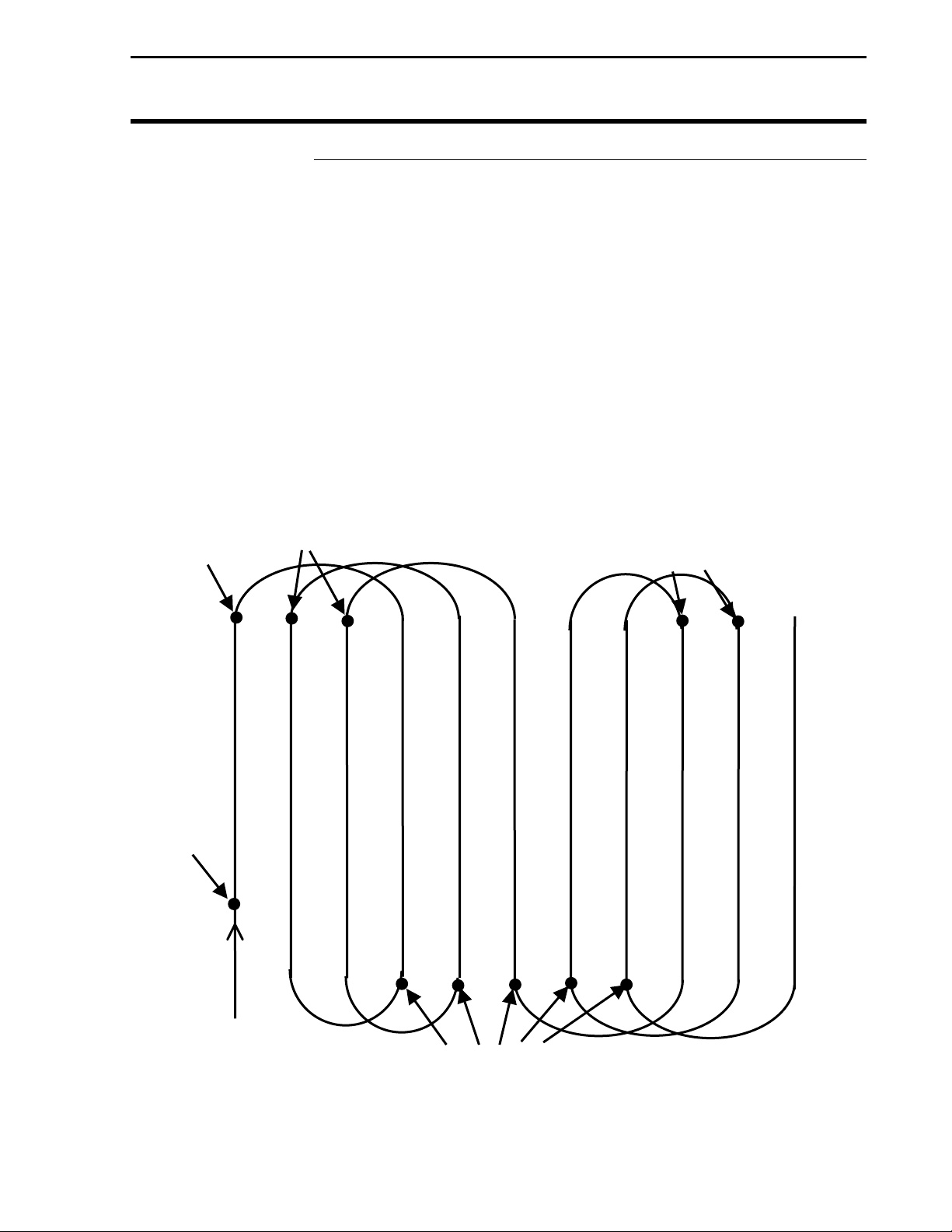
When using curve following pattern, guidance is provided parallel to
the previously driven swath.
While driving a swath, the GPS receiver records the swath location.
When the swath is incremented, positions logged are offset in the turn
direction. Guidance begins down the offset positions. Meanwhile,
new positions are logged for the current swath. When the swath
increments, the new positions are offset and guidance begins down the
next swath. The cycle repeats until guidance is reset.
Because of limited memory capacity, only the positions representing
the current and next swath are stored. Positions representing previous
swaths are deleted.
To help operators anticipate upcoming turns; a turn signal has been
added to the Light Bar. As turns approach, the lightbar illuminates in
the turn direction. The more LEDs illuminated, the sharper the turn.
The turn signal indicates a swath turn at twice the look-ahead distance.
By default, the turn signal occurs six seconds before the turn is
required.
Headlands specify field zones that have specific meaning. In some
applications, it may be an area where chemical application is not
desired. In other applications, the headland can be used to turn
equipment and move to the next swath. Its most simple function might
be to indicate the end of swath.
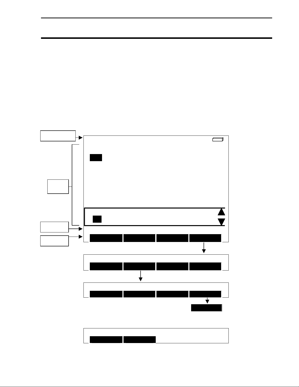
Power up the PF monitor.
Press the MENU key until OPTIONS is displayed and press OPTIONS
key.
Under OPTIONS press the LIGHTBAR key. (See Figure 10)
The key settings perform the following functions:
SET A: Sets the beginning of the first swath.
SET B: Sets the end of the first swath.
General Operation
February 2003 Rev.3 3000135
13
Page 18
General Operation
<
<
Screen Info Line
F1: HOME 40 L1: ENDS DG >
Light Bar
Ag Leader Technology
headland points are cleared.
Pause: Used to leave the field in mid swath. Press once to
disable guidance. Leave the swath. The system guides
back to the pause location. Press this key again to
resume swathing.
ADD/STRT: Adds a point to the headland or starts logging
headland points.
CLR/STOP: Deletes the last point entered from the headland
or stops logging headland points.
Reset: Resets Guidance to begin a new field. Pattern and
TARGET
[auto man]
TOTAL SEEDS
Active
Display
AREA
PASS NUMBER
< left right >
Status Line
Menu Line
OPTIONS SELECTIONS
LIGHTBAR
Application: CORN 1 AREA ON
FIELD LOAD SHOW MAP OPTIONS
Application: CORN 1 AREA ON
MARKS LIGHTBAR NAV BoUNDARY
Application: CORN 1 AREA ON
SET A SET B RESET PAUSE
PRESS < > TO GET ADDITIONAL SELECTIONS
Application: CORN AREA ON
ADD/STRT CLR/STOP
300125
Figure 10
160
10.1
A-B
bu/ac
sds
acres
>
RESUME
>
3 Rev.3 3000135
14
February
200
Page 19

Light Bar
Ag Leader Technology
Basic A-B Parallel
Swathing using
AUTO or Snap
Use this type of pattern when no headlands are required and the field is
going to be driven in a straight parallel swath pattern. Refer to the PF
monitor Setup for Guidance Section on page 23 for the procedures to
set the following:
Pattern: Set to NONE
Headland Type: Set to NONE
Swath Direction: Set to AUTO or SNAP
Look – Ahead, Display Mode, Swath Width and Units Display should
be established to your preference or situation.
Before making your first pass:
Press MENU key until OPTIONS is displayed and press OPTIONS
key.
Press the LIGHTBAR key.
Press the RESET key to clear all points in memory.
NOTE: Before working in a new field, you should reset the system
to clear previous field information.
When you begin your first pass, press SET A key. (See Figure 11.)
At the end of the first pass press SET B key.
NOTE: SET B cannot be set without first setting SET A.
General Operation
February 2003 Rev.3 3000135
15
Page 20

General Operation
Ag Leader Technology
Light Bar
Set B
Set A
Direction of Travel
Figure 11.
Basic A-B Parallel Swathing with Auto or Snap to swath increment.
NOTE: You may manually override Auto or Snap by using the UP or DOWN ARROW
keys. Using the manual override will not change the setting of Auto or Snap. The system
will default back to Auto or Snap after overriding.
IMPORTANT: In order to use the UP or DOWN ARROW, the Lightbar pass
number must be displayed on the screen of the PF monitor.
16
February 2003 Rev.3 3000135
Page 21

Light Bar
Ag Leader Technology
Set B
Set turn
direction to
left or right
of A-B
reference
line
Set A
Direction of Travel
IMPORTANT: In order to use the UP or DOWN ARROW,
number must be displayed on the screen of the PF monitor.
UP
ARROW
UP
ARROW
UP
ARROW
Basic A-B Parallel Swathing with Manual Increment
To use Manual Increment:
Have Lightbar Pass Number item displayed on the PF monitor screen.
Set swath direction under GPS/Guidance to left or right of A-B line.
At the Set B spot, of the current swath, press the UP ARROW to increase
your pass number and down arrow to decrease the pass number.
UP
ARROW
UP
ARROW
Figure 12
UP
ARROW
UP
ARROW
General Operation
UP
ARROW
UP
ARROW
the Lightbar pass
February 2003 Rev.3 3000135
17
Page 22

General Operation
C-Clamp Pattern
Light Bar
Ag Leader Technology
This pattern may be used in a field you want to work in a parallel A-B
pattern. The ends of the fields are sprayed as headlands so the parallel
A-B passes are made with minimal overlap in the headland zones.
Pattern: Set to None
Headland pattern: Set to C-Clamp
NOTE: Before working in a new field, you should reset the
system to clear previous field information.
IMPORTANT: In order to use the UP or DOWN ARROW,
the Lightbar pass number must be displayed on the screen of
the PF Monitor.
18
Figure 13. Straight Parallel pattern with C-clamp headland.
February 2003 Rev.3 3000135
Page 23

Light Bar
p
Ag Leader Technology
C-Clamp PatternCurve Following
Figure 13a. Curved Following pattern with C-clamp headland.
Use this pattern when working an irregularly shaped field. Guidance in
curve following mode is always based on the previous swath after the
initial A-B line is established. The ends of the fields are sprayed as
headlands so the parallel curved passes are made with minimal overlap in
the headland zones.
Pattern: Curved
Headland pattern: Set to C-Clamp
NOTE: Before working in a new field, you should reset the
system to clear previous field information.
IMPORTANT: In order to use the UP or DOWN ARROW,
the Lightbar pass number must be displayed on the screen of
the PF Monitor.
CLR/
Sto
Set A
Set B
Add/
Start
Up Arrow
General Operation
Up
Arrow
Up Arrow
Red
Orange
Orange
Red
Up Arrow Up Arrow Up Arrow
Up
Arrow
February 2003 Rev.3 3000135
19
Page 24

General Operation
Double Curved
Headland, Straight
Pattern
Figure 14. Straight Parallel Pattern with a double curved headland.
Light Bar
Ag Leader Technology
This pattern may be used in a field you want to work in a parallel A-B
pattern. The ends of the fields are sprayed as headlands so the parallel
A-B passes are made with minimal overlap in the headland zones.
Pattern: Set to None
Headland pattern: Set to Curved
NOTE: Before working in a new field, you should reset the
system to clear previous field information.
IMPORTANT: In order for this pattern to function properly
the Lightbar pass number must be displayed on the screen of
the PF monitor.
18
March 2001 Rev.1 3000135
Page 25

Light Bar
Ag Leader Technology
Straight Parallel
Swathing with A-B
Endzone Headlands
Set B
Set A
Basic Straight Parallel Swathing with A-B Endzones as the headland type
Use this pattern when headlands are required at both ends of a
rectangular field and the field is driven in a straight parallel swath
pattern. Headland locations are determined by the A and B points on
the A-B reference line. Headlands are generated perpendicular to the
A-B line at both ends of the field. The A-B points mark the center of
the headlands at either end of the field.
The Approach LED illuminates green when the vehicle is inside the
headlands boundary. The Approach LED changes to red upon crossing
the headland boundary.
Pattern: Set to NONE.
Headland pattern: Set to A-B Endzone.
NOTE: Before working in a new field, you should reset the
system to clear previous field information.
General Operation
Approach LED Color
Red
Green
Red
Figure 15.
May 2001 Rev.2 3000135
19
Page 26

General Operation
A
r
Straight Parallel
Swathing with
Closed Circuit
Headland
ADD/STRT
ADD/STRT
Set B
Basic Straight Parallel Swathing with a single Closed Circuit Headland
Light Bar
Ag Leader Technology
Use this pattern when headlands are required, the ends of the field are
irregularly shaped, and the field is driven in a straight parallel swath
pattern. The headland location is determined by the position of the
headland points along the outside field boundary. Headlands are
generated one swath width along the field boundary according to the
manually entered headland points. The system automatically closes the
headland boundary by connecting the first and last headland point.
The Approach LED illuminates green when the vehicle is inside the
headland boundary. The Approach LED changes to red upon crossing
the headland boundary.
Pattern: Set to NONE.
Headland pattern: Set to Closed Circuit.
Direction of Travel
Set A
1/2 Swath Width
Figure 16
ADD/STRT
ADD/STRT
Red
Green
Red
pproach LED
Colo
20
May 2001 Rev.2 3000135
Page 27

Light Bar
A
Ag Leader Technology
Straight Parallel
Swathing with
Curved Headlands
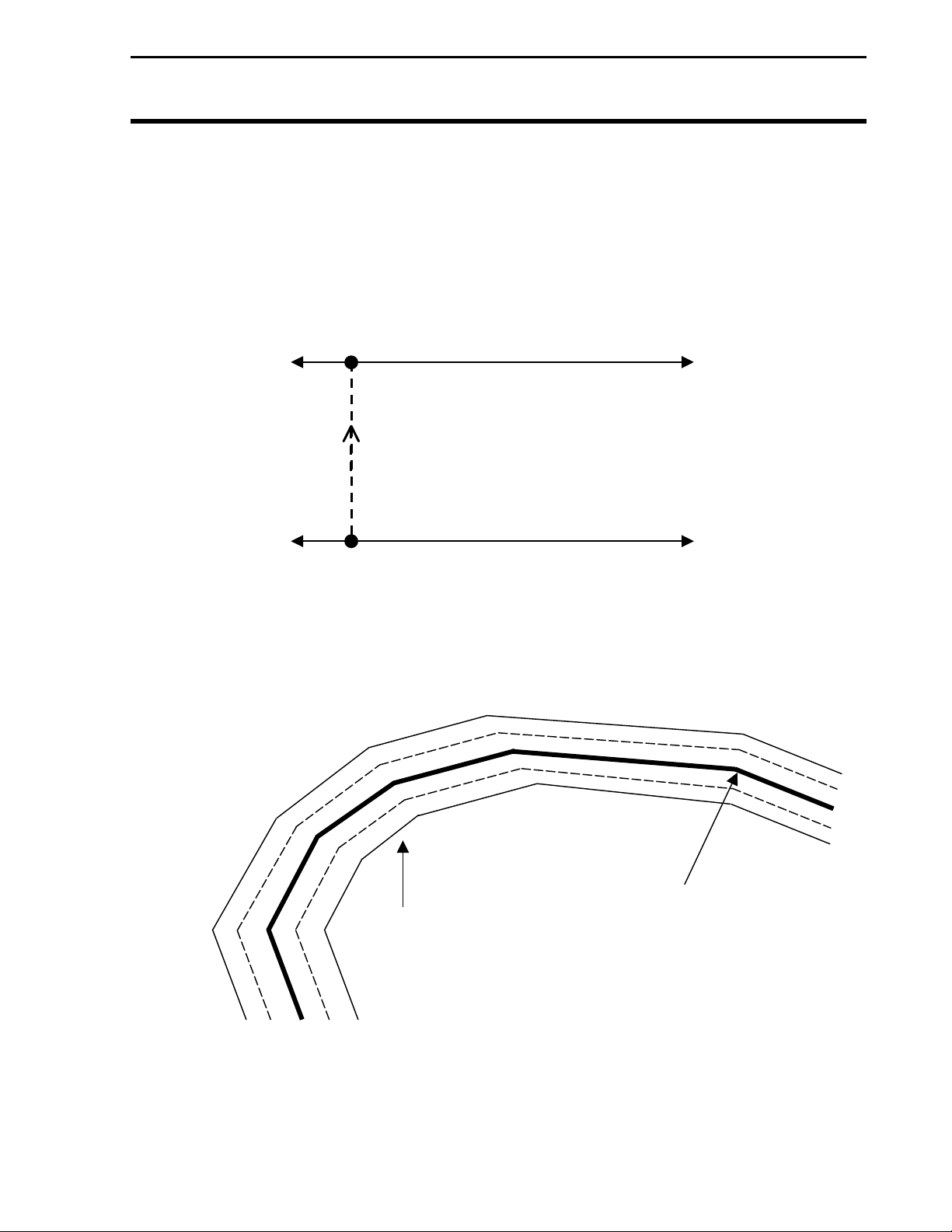
Basic Straight Parallel Swathing with a single Curved Headland
Use this pattern in an irregularly shaped field that is still worked in a
parallel straight pattern. The irregularly shaped boundary can be
recorded as a sprayed headland using curved headlands, so the
following straight parallel passes can be made with minimal overlap
into the headland zone.
The Light Bar will prompt you to Set B after you press ADD/STRT
when beginning the circuit, ignore this message. Continue to the end
of the circuit and press CLR/STOP. Then press Set A and resume
following Light Bar prompts to begin parallel swathing.
The Approach LED illuminates green when the unit is inside the
headland boundary. As the unit approaches the edge of the headland
boundary the Approach LED changes to orange within 1/2 swath width
of the sprayed headland edge and to red upon crossing the headland
edge.
NOTE: If you pass beyond the outer orange band in this mode, the
Approach LED changes back to Green (See Figure 15).
Pattern: Set to None.
Headland pattern: Set to Curved.
Figure 17
General Operation
1/2 Swath
DD/STRT
Approach LED
May 2001 Rev.2 3000135
23
Page 28

General Operation
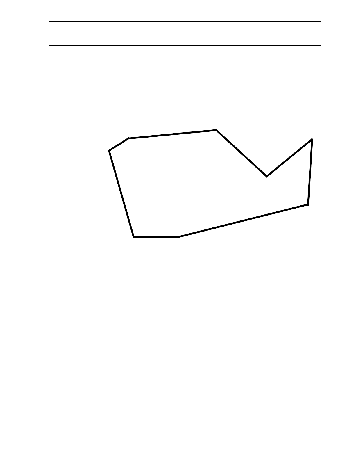
A
Parallel A-B on
Center Pivots
Light Bar
Ag Leader Technology
Use this pattern for spraying crops that are irrigated with a center pivot
when only sections of the entire circle are to be sprayed or worked.
This pattern is typically used where more than one type of crop is
irrigated by one pivot and no (or minimal) furrows exist.
The Approach LED illuminates green when inside the headland
boundary. When approaching the edge of headland boundary the
Approach LED changes to orange within 1/2 swath width of the
sprayed edge and to red upon crossing the headland edge.
Pattern: Set to NONE.
Headland pattern: Set to Curved.
NOTE: Before working in a new field, you should reset the
system to clear previous field information.
ADD/STRT
Set B
Figure 18.
Straight Parallel swathing with Curved Headlands
pproach
LED Color
Red
Orange
Green
Green
Set A
CLR/STOP
24
May 2001 Rev.2 3000135
Page 29

Light Bar
Ag Leader Technology
A + Pattern
Set the angle from true north that you want to swath. As you
begin to make your first pass, press Set A. When you get to the
end of your first pass, turn into your next pass and the lightbar
will guide you on the reverse angle you set.
Pattern: Set to A+ Heading.
Headland pattern: Set to None.
Baseline heading: 315 degrees (Example)
Below is an example of the settings an operator may choose to
establish the desired heading across a field.
Figure 19. A+ Swath pattern
General Operation
Direction of travel
at 315 degrees
May 2001 Rev.2 3000135
25
Page 30

General Operation
Curve Following
Set B
Set A
Light Bar
Ag Leader Technology
Use this pattern when working an irregularly shaped field. Guidance in
curve following mode is always based on the previous swath after the
initial A-B line is established.
Pattern: Set to Curve.
Headland pattern: Set to curved (this happens by default with this
pattern setting).
NOTE: Before working in a new field, you should reset the
system to clear previous field information.
IMPORTANT: In order for this pattern to function
properly the Lightbar pass number must be displayed on
the screen of the PF monitor.
Set B or UP ArrowSet B or UP Arrow
Set B
or UP
Arrow
Figure 20. Curve Pattern
Set B
or UP
Arrow
Set B
or UP
Arrow
24
February 2003 Rev.3 3000135
Page 31

Light Bar
Ag Leader Technology
Curve Following on
Pivots
Use this pattern for crops that are irrigated with a center pivot. It is
typically used on center pivots where crops irrigated by the pivot have
furrows around the center of the circle or when the pivot tracks become
difficult to navigate.
Pattern: Set to Curved.
Headland pattern: Set to None
Figure 21. Curve Pattern – Center Pivot
General Operation
NOTE: Before working in a new field, you should reset the
system to clear previous field information.
IMPORTANT: In order for this pattern to function
properly the Lightbar pass number must be displayed on
the screen of the PF monitor.
Set B
Set B or UP Arrow
Set B or UP Arrow
Set A
May 2001 Rev.2 3000135
25
Page 32

General Operation
Curve Following
with Curved
Headlands
Press
ADD/STRT
UP Arrow
Figure 22. Curve Pattern with Curved Headlands
Light Bar
Ag Leader Technology
Use this pattern when headlands are required on all sides of a field that
is irregularly shaped. Double headland passes and curved swath lines
can also be implemented in this mode. Guidance in Curve Following
mode is always based on the previous swath after the initial A-B line is
established.
The Approach LED illuminates green when inside the headland
boundary. When approaching the edge of a headland boundary, the
Approach LED changes to orange within 1/2 swath width of the
sprayed edge and to red upon crossing the headland edge.
Pattern: Set to Curve.
Headland pattern: Set to Curved.
IMPORTANT: In order for this pattern to function properly the
Lightbar pass number must be displayed on the screen of the PF
monitor.
NOTE: Before working in a new field, you should reset the
system to clear previous field information.
Set B or UP Arrow
Set B or UP Arrow
CLR/STOP
Set B or UP Arrow Set B or UP Arrow
Set B or UP Arrow
26
February 2003 Rev.3 3000135
Page 33

Light Bar
y
y
Ag Leader Technology
Spiral
Set A
Use this pattern when the operating pattern within a field dictates
continuous application from the center out or outside in. Using the
curved guidance spiral pattern, a field can be worked continuously and
completely using no headlands.
This pattern is not recommended for fields under 10 acres. Fields with
long runs may cause erratic behavior. The more contour to a swath the
better this pattern will perform. At the start of a new guided pass, it
may take a short period of time for the lightbar to determine your
location and guidance pattern.
Pattern: Set to Curved Spiral.
Headland Pattern: Set to None.
Up Arrow Ke
General Operation
IMPORTANT: In order to use the UP or DOWN ARROW,
the Lightbar pass number must be displayed on the screen
of the PF monitor.
NOTE: Depending on the direction that your want to spiral,
you increment the pass in the following manner:
Up Arrow =Right, Down Arrow = Left
NOTE: Before working in a new field, you should reset the
system to clear previous field information.
Up Arrow Ke
Figure 23. Curved Spiral Pattern
May 2001 Rev.2 3000135
29
Page 34
General Operation
ARRO
ARRO
Skip with No
Headlands
Set B
Set A
Press UP
Figure 24. Parallel swathing with Pass Skips
Light Bar
Ag Leader Technology
Use this pattern when the equipment being used to work a field
requires a larger turning radius than the standard parallel A-B pattern
allows. Skip enables the operator to specify the number of swaths to
skip between passes and provides racetrack guidance across the field
accordingly.
Pattern: Set to Skip Pass.
Headland Pattern: Set to None.
IMPORTANT: In order for this pattern to function
properly the Lightbar pass number must be displayed on
the screen of the PF monitor.
NOTE: Before working in a new field, you should reset the
system to clear previous field information.
W KEY
Press UP
ARROW key
Press UP
W key
30
February 2003 Rev.3 3000135
Page 35

Light Bar
Ag Leader Technology
Using In-Field
Guidance
LED Sensitivity
Figure 25. Approach LED Sensitivity with Pause/Resume Point
The Pause/Resume feature disables lightbar guidance in mid-swath.
You can leave the swath, navigate back to the work location and resume
swathing.
By pressing the pause/resume key, you can leave the current swath.
When restarting, the lightbar provides guidance to help align the vehicle
with the swath that was active when guidance was paused. To use the
lightbar to find the active swath:
The LED illuminates green when the vehicle is within the
Approach LED sensitivity setting of the pause.
When the LED turns green, press resume to continue. See
Figure 25 for an example.
General Operation
Pass Direction
Approach LED
Sensitivity
Red
Amber
Pause/Resume Point
Green
Amber
Red
***
May 2001 Rev.2 3000135
31
Page 36

PF3000 or PF3000 Pro Setup for Light Bar
PF Series monitors Setup for Lightbar
1. Power up the PF monitor.
2. Press MENU key until SETUP is displayed and select SETUP.
3. Press the left or right arrow keys to select GPS.
4. At the GPS Setup screen, use the up or down arrow key to scroll
down until Light Bar is highlighted and press EDIT key. (Figure
26)
GPS SETUP
NEMA MESSAGES
GPS/PORT CONFIGURATION
BEACON DIFFERENTIAL
SATELLITE DIFFERENTIAL
LIGHT BAR
GUIDANCE
EDIT
Figure 26.
Light Bar
Ag Leader Technology
EXIT
30
March 2001 Rev.1 3000135
Page 37

Light Bar
Ag Leader Technology
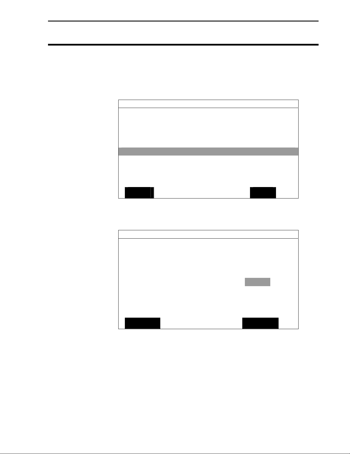
5. With the Lightbar Status line highlighted, press EDIT key. (Figure
27) Change the lightbar status to ON or OFF and press ACCEPT
key. (Figure 28)
GPS/LIGHTBAR
Lightbar Status OFF
Mounting Position Dash
Brightness (1-5) 5
Text Mode PASS # & ERROR
Proximity Sensitivity 25 ft
LED Spacing Mode LINEAR
LED Spacing 5.0 ft
End Distance --- ft
EDIT
GPS/LIGHTBAR
Lightbar Status ON
Mounting Position Dash
Brightness (1-5) 5
Text Mode PASS # & ERROR
Proximity Sensitivity 25 ft
LED Spacing Mode LINEAR
LED Spacing 5.0 ft
End Distance --- ft
ACCEPT
PF3000 or PF3000 Pro Setup for Light Bar
Figure 27.
Figure 28.
EXIT
CANCEL
March 2001 Rev.1 3000135
31
Page 38

PF3000 or PF3000 Pro Setup for Light Bar
Ag Leader Technology
Light Bar
6. Scroll down to Mounting Position and press EDIT key (Figure 29).
Use the up or down arrow key to select “Dash” or “Ceiling”
mounting and press ACCEPT key. (Figure 30) Selecting ceiling
mount will invert the text
GPS/LIGHTBAR
Lightbar Status OFF
Mounting Position Dash
Brightness (1-5) 5
Text Mode PASS # & ERROR
Proximity Sensitivity 25 ft
LED Spacing Mode LINEAR
LED Spacing 5.0 ft
End Distance --- ft
EDIT
EXIT
Figure 29.
GPS/LIGHTBAR
Lightbar Status ON
Mounting Position Dash
Brightness (1-5) 5
Text Mode PASS # & ERROR
Proximity Sensitivity 25 ft
LED Spacing Mode LINEAR
LED Spacing 5.0 ft
End Distance --- ft
ACCEPT
CANCEL
Figure 30.
32
March 2001 Rev.1 3000135
Page 39

Light Bar
Ag Leader Technology
PF Monitor Setup for Light Bar
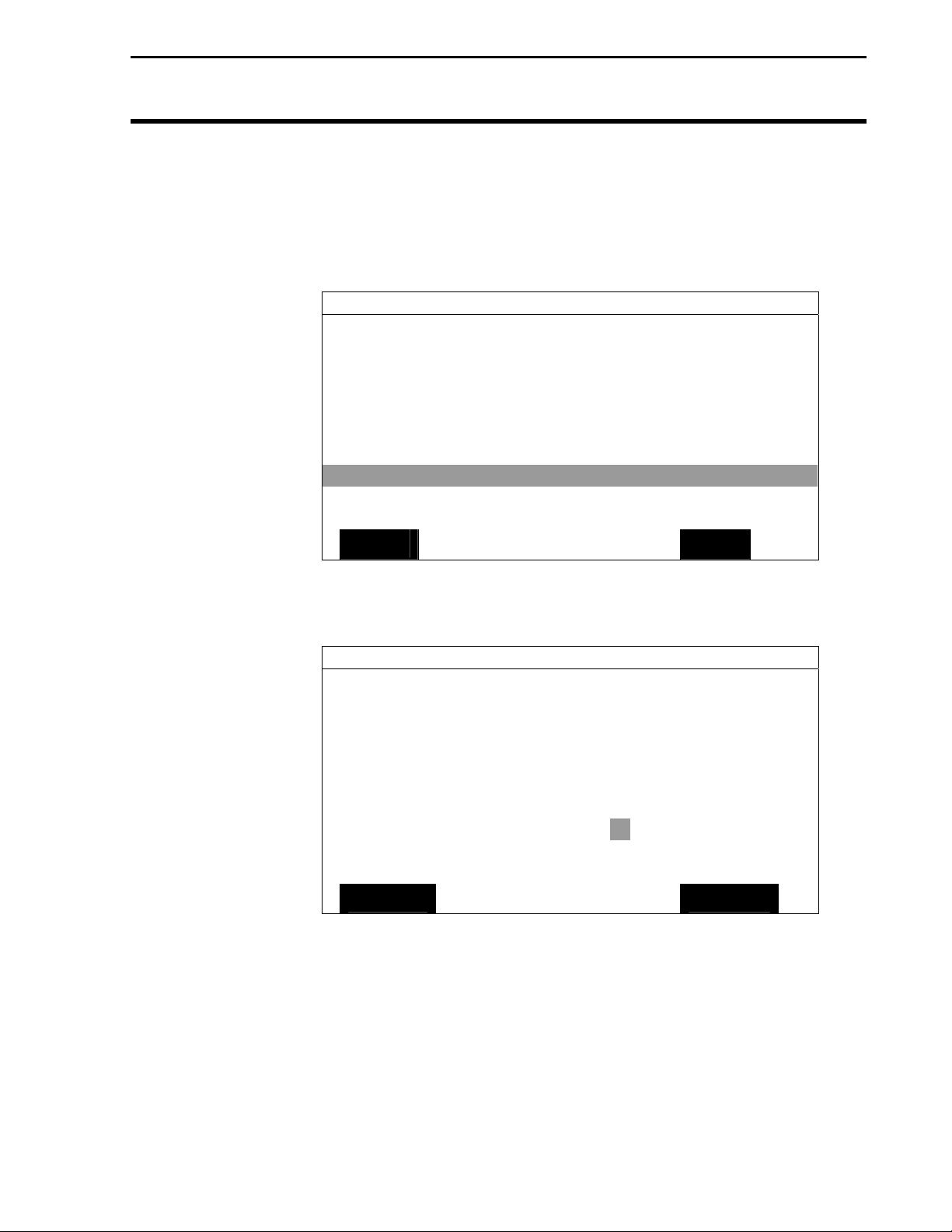
7. Scroll down to Brightness and press EDIT key. (Figure 31) Use
the up or down arrow key to select the lightbar display brightness
from 1 (dimmest) to 5 (brightest) and press ACCEPT key. (Figure
32)
GPS/LIGHTBAR
Lightbar Status OFF
Mounting Position Dash
Brightness (1-5) 5
Text Mode PASS # & ERROR
Proximity Sensitivity 25 ft
LED Spacing Mode LINEAR
LED Spacing 5.0 ft
End Distance --- ft
EDIT
EXIT
Figure 31.
GPS/LIGHTBAR
Lightbar Status ON
Mounting Position Dash
Brightness (1-5) 5
Text Mode PASS # & ERROR
Proximity Sensitivity 25 ft
LED Spacing Mode LINEAR
LED Spacing 5.0 ft
End Distance --- ft
ACCEPT
CANCEL
Figure 32.
March 2001 Rev.1 3000135
33
Page 40

PF3000 or PF3000 Pro Setup for Light Bar
Ag Leader Technology
Light Bar
8. Use the down arrow key to scroll down until Text Mode is
highlighted (Figure 33) and press EDIT key. Use the up or down
arrow key to select one of the following and press ACCEPT key
(Figure 34):
Pass # and Error Cross-TRK Error
No Text True Heading
Curve Arrows Demo
End Line Dist Pass & Speed
Start Line Dist Ground Speed
Pass # Heading Error
GPS Status
GPS/LIGHTBAR
Lightbar Status OFF
Mounting Position Dash
Brightness (1-5) 5
Text Mode PASS # & ERROR
Proximity Sensitivity 25 ft
LED Spacing Mode LINEAR
LED Spacing 5.0 ft
End Distance --- ft
EDIT
EXIT
Figure 33.
GPS/LIGHTBAR
Lightbar Status ON
Mounting Position Dash
Brightness (1-5) 5
Text Mode PASS # & ERROR
Proximity Sensitivity 25 ft
LED Spacing Mode LINEAR
LED Spacing 5.0 ft
End Distance --- ft
ACCEPT
CANCEL
Figure 34.
34
March 2001 Rev.1 3000135
Page 41

Light Bar
Ag Leader Technology
PF Monitor Setup for Light Bar
9. Scroll down to Proximity Sensitivity and press EDIT key. (Figure
35) Use the up or down arrow key to select a setting from 1 to 99 ft
and press ACCEPT key. (Figure 36)
GPS/LIGHTBAR
Lightbar Status OFF
Mounting Position Dash
Brightness (1-5) 5
Text Mode PASS # & ERROR
Proximity Sensitivity 25 ft
LED Spacing Mode LINEAR
LED Spacing 5.0 ft
End Distance --- ft
EDIT
EXIT
Figure 35.
GPS/LIGHTBAR
Lightbar Status ON
Mounting Position Dash
Brightness (1-5) 5
Text Mode PASS # & ERROR
Proximity Sensitivity 25 ft
LED Spacing Mode LINEAR
LED Spacing 5.0 ft
End Distance --- ft
ACCEPT
CANCEL
Figure 36.
March 2001 Rev.1 3000135
35
Page 42
PF Monitor Setup for Light Bar
Ag Leader Technology
Light Bar
10. Scroll down to LED Spacing Mode and press EDIT key. (Figure
37) Use the up or down arrow key to select "Linear" or "Scaled"
and press ACCEPT key (Figure 38).
GPS/LIGHTBAR
Lightbar Status OFF
Mounting Position Dash
Brightness (1-5) 5
Text Mode PASS # & ERROR
Proximity Sensitivity 25 ft
LED Spacing Mode LINEAR
LED Spacing 5.0 ft
End Distance --- ft
EDIT
EXIT
Figure 37.
GPS/LIGHTBAR
Lightbar Status ON
Mounting Position Dash
Brightness (1-5) 5
Text Mode PASS # & ERROR
Proximity Sensitivity 25 ft
LED Spacing Mode LINEAR
LED Spacing 5.0 ft
End Distance --- ft
ACCEPT
CANCEL
Figure 38.
36
March 2001 Rev.1 3000135
Page 43

Light Bar
Ag Leader Technology
PF Monitor Setup for Light Bar
11. Scroll down to LED Spacing and press EDIT key. (Figure 39) Use
the up or down arrow keys to select a setting from 0.1 to 9.9 ft and
press ACCEPT key. (Figure 40)
GPS/LIGHTBAR
Lightbar Status OFF
Mounting Position Dash
Brightness (1-5) 5
Text Mode PASS # & ERROR
Proximity Sensitivity 25 ft
LED Spacing Mode LINEAR
LED Spacing 5.0 ft
End Distance --- ft
EDIT
EXIT
Figure 39.
GPS/LIGHTBAR
Lightbar Status ON
Mounting Position Dash
Brightness (1-5) 5
Text Mode PASS # & ERROR
Proximity Sensitivity 25 ft
LED Spacing Mode LINEAR
LED Spacing 5.0 ft
End Distance --- ft
ACCEPT
CANCEL
Figure 40.
March 2001 Rev.1 3000135
37
Page 44

PF Monitor Setup for Light Bar
Ag Leader Technology
Light Bar
12. Scroll down to End Distance and press EDIT key. (Figure 41) If
SCALED is used, the first 10 LED’s are normal spacing and the
remaining LED distance represents the difference to the end
distance. Enter that value and press ACCEPT key. (Figure 42)
GPS/LIGHTBAR
Lightbar Status OFF
Mounting Position Dash
Brightness (1-5) 5
Text Mode PASS # & ERROR
Proximity Sensitivity 25 ft
LED Spacing Mode LINEAR
LED Spacing 5.0 ft
End Distance --- ft
EDIT
EXIT
Figure 41.
GPS/LIGHTBAR
Lightbar Status ON
Mounting Position Dash
Brightness (1-5) 5
Text Mode PASS # & ERROR
Proximity Sensitivity 25 ft
LED Spacing Mode LINEAR
LED Spacing 5.0 ft
End Distance --- ft
ACCEPT
CANCEL
Figure 42.
13. Press EXIT key to return to GPS Setup screen.
***
38
March 2001 Rev.1 3000135
Page 45

Light Bar
Ag Leader Technology
PF Series monitor
Setup for
Guidance
1. At the GPS Setup screen, scroll down to Guidance and press EDIT
key. (Figure 43)
Figure 43.
PF3000 or PF3000 Pro Setup for Guidance
GPS SETUP
GPS/PORT CONFIGUREATION
BEACON DIFFERENTIAL
SATELLITE DIFFERENTIAL
EDIT
NEMA MESSAGES
LIGHT BAR
GUIDANCE
EXIT
March 2001 Rev.1 3000135
39
Page 46

PF3000 or PF3000 Pro Setup for Guidance
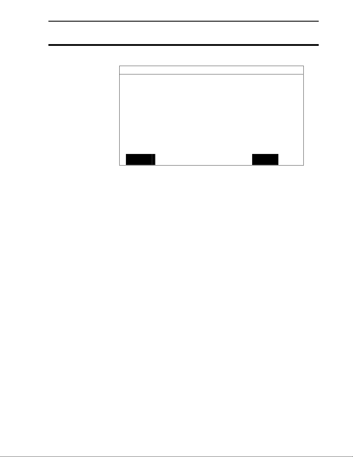
2. With Pattern highlighted, press EDIT key. (Figure 44) Use the up
or down arrow keys to select one of the following and press
ACCEPT key (Figure 45):
None
A+ Heading
Curve Spiral
Curve
Skip Pass
GPS/GUIDANCE
Pattern NONE
Headland Type CURVED
Look – Ahead 3 SEC
Display Mode SHOW CORRECTION
Swath Direction Auto
Swath Width 60.0 ft
Antenna Offset 20.0 ft
Pass Skips 15
Units Displayed English
Contour Log Interval HEADING CHANGE
EDIT
Figure 44.
GPS/GUIDANCE
Pattern CURVE
Headland Type CURVED
Look – Ahead 3 SEC
Display Mode SHOW CORRECTION
Swath Direction Auto
Swath Width 60.0 ft
Antenna Offset 20.0 ft
Pass Skips 15
Units Displayed English
Contour Log Interval HEADING CHANGE
ACCEPT
Figure 45.
Light Bar
Ag Leader Technology
EXIT
CANCEL
40
March 2001 Rev.1 3000135
Page 47

Light Bar
Ag Leader Technology
3. Scroll down to Headland Type and press EDIT key. (Figure 46)
Use the up or down arrow key to select one of the following and
press ACCEPT key (Figure 47):
GPS/GUIDANCE
Pattern NONE
Headland Type CURVED
Look – Ahead 3 SEC
Display Mode SHOW CORRECTION
Swath Direction Auto
Swath Width 60.0 ft
Antenna Offset 20.0 ft
Pass Skips 15
Units Displayed English
Contour Log Interval HEADING CHANGE
EDIT
GPS/GUIDANCE
Pattern CURVE
Headland Type CURVED
Look – Ahead 3 SEC
Display Mode SHOW CORRECTION
Swath Direction Auto
Swath Width 60.0 ft
Antenna Offset 20.0 ft
Pass Skips 15
Units Displayed English
Contour Log Interval HEADING CHANGE
ACCEPT
PF3000 or PF3000 Pro Setup for Guidance
None C-Clamp Curved
Closed Circuit A-B End Zones
Figure 46.
Figure 47.
EXIT
CANCEL
March 2001 Rev.1 3000135
41
Page 48

PF Monitor Setup for Guidance
4. Scroll down to Look – Ahead and press EDIT key. (Figure 48)
Use the up or down arrow key to select from 0 to 9 seconds and
press ACCEPT key. (Figure 49)
GPS/GUIDANCE
Pattern NONE
Headland Type CURVED
Look – Ahead 3 SEC
Display Mode SHOW CORRECTION
Swath Direction Auto
Swath Width 60.0 ft
Antenna Offset 20.0 ft
Pass Skips 15
Units Displayed English
Contour Log Interval HEADING CHANGE
EDIT
GPS/GUIDANCE
Pattern CURVE
Headland Type CURVED
Look – Ahead 3 SEC
Display Mode SHOW CORRECTION
Swath Direction Auto
Swath Width 60.0 ft
Antenna Offset 20.0 ft
Pass Skips 15
Units Displayed English
Contour Log Interval HEADING CHANGE
ACCEPT
Light Bar
Ag Leader Technology
EXIT
Figure 48.
CANCEL
Figure 49.
42
March 2001 Rev.1 3000135
Page 49

Light Bar
Ag Leader Technology
5. Scroll down to Display Mode and press EDIT key. (Figure 50)
Use the up or down arrow key to select “Show Correction” or
“Show Error” and press ACCEPT key. (Figure 51)
GPS/GUIDANCE
Pattern NONE
Headland Type CURVED
Look – Ahead 3 SEC
Display Mode SHOW CORRECTION
Swath Direction Auto
Swath Width 60.0 ft
Antenna Offset 20.0 ft
Pass Skips 15
Units Displayed English
Contour Log Interval HEADING CHANGE
EDIT
GPS/GUIDANCE
Pattern CURVE
Headland Type CURVED
Look – Ahead 3 SEC
Display Mode SHOW CORRECTION
Swath Direction Auto
Swath Width 60.0 ft
Antenna Offset 20.0 ft
Pass Skips 15
Units Displayed English
Contour Log Interval HEADING CHANGE
ACCEPT
PF Monitor Setup for Guidance
Figure 50.
Figure 51.
EXIT
CANCEL
March 2001 Rev.1 3000135
43
Page 50

PF Monitor Setup for Guidance
6. Scroll down to Swath Direction and press EDIT key. (Figure 52)
Use the up or down arrow key to select one of the following and
press ACCEPT key (Figure 53):
AUTO LEFT
RIGHT SNAP (Default)
GPS/GUIDANCE
Pattern NONE
Headland Type CURVED
Look – Ahead 3 SEC
Display Mode SHOW CORRECTION
Swath Direction Auto
Swath Width 60.0 ft
Antenna Offset 20.0 ft
Pass Skips 15
Units Displayed English
Contour Log Interval HEADING CHANGE
EDIT
GPS/GUIDANCE
Pattern CURVE
Headland Type CURVED
Look – Ahead 3 SEC
Display Mode SHOW CORRECTION
Swath Direction Auto
Swath Width 60.0 ft
Antenna Offset 20.0 ft
Pass Skips 15
Units Displayed English
Contour Log Interval HEADING CHANGE
ACCEPT
Light Bar
Ag Leader Technology
EXIT
Figure 52.
CANCEL
Figure 53.
44
March 2001 Rev.1 3000135
Page 51

Light Bar
Ag Leader Technology
7. Scroll down to Swath Width and press EDIT key. (Figure 54) Use
the up or down arrow key to set swath width from 0.1 to 100.0 ft
and press ACCEPT key (Figure 55).
GPS/GUIDANCE
Pattern NONE
Headland Type CURVED
Look – Ahead 3 SEC
Display Mode SHOW CORRECTION
Swath Direction Auto
Swath Width 60.0 ft
Antenna Offset 20.0 ft
Pass Skips 15
Units Displayed English
Contour Log Interval HEADING CHANGE
EDIT
GPS/GUIDANCE
Pattern CURVE
Headland Type CURVED
Look – Ahead 3 SEC
Display Mode SHOW CORRECTION
Swath Direction Auto
Swath Width 60.0 ft
Antenna Offset 20.0 ft
Pass Skips 15
Units Displayed English
Contour Log Interval HEADING CHANGE
ACCEPT
PF Monitor Setup for Guidance
Figure 54.
Figure 55.
EXIT
CANCEL
March 2001 Rev.1 3000135
45
Page 52

PF Monitor Setup for Guidance
8. Scroll down to Antenna Offset and press EDIT key. (Figure 56)
Use the up or down arrow key to set Antenna Offset from –100 to
+100 ft and press ACCEPT key. (Figure 57)
NOTE: Antenna Offset could be a negative number if your spray
boom is mounted in front of the antenna. Positive numbers indicate
a boom mounted behind the antenna.
GPS/GUIDANCE
Pattern NONE
Headland Type CURVED
Look – Ahead 3 SEC
Display Mode SHOW CORRECTION
Swath Direction Auto
Swath Width 60.0 ft
Antenna Offset 20.0 ft
Pass Skips 15
Units Displayed English
Contour Log Interval HEADING CHANGE
EDIT
GPS/GUIDANCE
Pattern CURVE
Headland Type CURVED
Look – Ahead 3 SEC
Display Mode SHOW CORRECTION
Swath Direction Auto
Swath Width 60.0 ft
Antenna Offset 20.0 ft
Pass Skips 15
Units Displayed English
Contour Log Interval HEADING CHANGE
ACCEPT
Light Bar
Ag Leader Technology
EXIT
Figure 56.
CANCEL
Figure 57.
46
March 2001 Rev.1 3000135
Page 53
Light Bar
Ag Leader Technology
9. Scroll down to Pass Skips and press EDIT key. (Figure 58) Use
the up or down arrow key to set Pass Skip from 0 to 99 and press
ACCEPT key. (Figure 59)
GPS/GUIDANCE
Pattern NONE
Headland Type CURVED
Look – Ahead 3 SEC
Display Mode SHOW CORRECTION
Swath Direction Auto
Swath Width 60.0 ft
Antenna Offset 20.0 ft
Pass Skips 15
Units Displayed English
Contour Log Interval HEADING CHANGE
EDIT
GPS/GUIDANCE
Pattern CURVE
Headland Type CURVED
Look – Ahead 3 SEC
Display Mode SHOW CORRECTION
Swath Direction Auto
Swath Width 60.0 ft
Antenna Offset 20.0 ft
Pass Skips 15
Units Displayed English
Contour Log Interval HEADING CHANGE
ACCEPT
PF Monitor Setup for Guidance
Figure 58.
Figure 59.
EXIT
CANCEL
March 2001 Rev.1 3000135
47
Page 54

PF Monitor Setup for Guidance
10. Scroll down to Units Displayed and press EDIT key. (Figure 60)
Use the up or down arrow key to set English or Metric and press
ACCEPT key. (Figure 61)
GPS/GUIDANCE
Pattern NONE
Headland Type CURVED
Look – Ahead 3 SEC
Display Mode SHOW CORRECTION
Swath Direction Auto
Swath Width 60.0 ft
Antenna Offset 20.0 ft
Pass Skips 15
Units Displayed English
Contour Log Interval HEADING CHANGE
EDIT
GPS/GUIDANCE
Pattern CURVE
Headland Type CURVED
Look – Ahead 3 SEC
Display Mode SHOW CORRECTION
Swath Direction Auto
Swath Width 60.0 ft
Antenna Offset 20.0 ft
Pass Skips 15
Units Displayed English
Contour Log Interval HEADING CHANGE
ACCEPT
Light Bar
Ag Leader Technology
EXIT
Figure 60
CANCEL
Figure 61
48
March 2001 Rev.1 3000135
Page 55

Light Bar
Ag Leader Technology
PF Monitor Setup for Guidance
11. Scroll down to Contour Log Interval and press EDIT key. (Figure
62) Use the up or down arrow key to set Swath Change or Heading
Change and press ACCEPT key. (Figure 63)
GPS/GUIDANCE
Pattern CURVE
Headland Type CURVED
Look – Ahead 3 SEC
Display Mode SHOW CORRECTION
Swath Direction Auto
Swath Width 60.0 ft
Antenna Offset 20.0 ft
Pass Skips 15
Units Displayed English
Contour Log Interval HEADING CHANGE
ACCEPT
CANCEL
Figure 62.
GPS/GUIDANCE
Pattern CURVE
Headland Type CURVED
Look – Ahead 3 SEC
Display Mode SHOW CORRECTION
Swath Direction Auto
Swath Width 60.0 ft
Antenna Offset 20.0 ft
Pass Skips 15
Units Displayed English
Contour Log Interval HEADING CHANGE
ACCEPT
CANCEL
Figure 63.
12. Press the EXIT key twice to return to the main operating screen.
***
February 2003 Rev.3 3000135
51
Page 56

Parts List
Ag Leader Technology
Light Bar
Parts List – Light Bar
Part Name/Description Part No. Quantity
Light Bar System 3001469 1
Light Bar Cable, 12 ft 2000933 1
Light Bar, Ag Leader 3000126 1
Manual – Ag Leader Light Bar 3000135 1
Light Bar Installation Kit 3000506 1
Dual-Lock – Type 170 (Window Side) 3 in. 2000052 3
Dual-Lock – Type 400 (Monitor Side) 3 in. 2000053 1
Alcohol Swab Pack 2002811 4
Grey Plastic Cable Clamps 2002812 6
Cable Tie – 6 in. black 2002817-6 10
Optional Suction Cup is ordered separately from the Light Bar
3-inch Suction Cup for Lightbar 3001475 1
50
March 2001 Rev.1 3000135
Page 57

Light Bar
Owners Registration
You will NOT receive upgrade/update information of this
product if you are not registered.
Return this sheet in the enclosed postage – paid envelope or
fax.
(Outside the USA 011) – 515-232-3595
Ag Leader Technology
2202 South Riverside Drive
P.O. Box 2348
Ames, Iowa 50010
Name:__________________________________________________________________
Street Address:___________________________________________________________
City, State, Country:_______________________________________________________
Postal or USA ZIP code:____________________________________________________
Phone # (including Country code or USA area code):_____________________________
Mobile Phone #:______________________ FAX #:_____________________
Email address:_________________________________________________
Ag Leader Dealer:______________________________________________
Dealer Address:___________________________________________________________
Intended Use (Please circle all that apply): Combine Sprayer Planter ATV
Other, please specify___________________________________________
Light Bar Serial #_____________________
PF monitor Serial #________________________
Add-On GPS3050 Serial #_______________
Add-On GPS3100 Serial #_______________
Add-On GPS 4100 Serial #_______________
Page 58

Page 59

Light Bar
Ag Leader Technology
Summary of Changes for 3000135
Revision 1 Completed April 2001. Incorporated two new patterns and the setup for them.
Incorporated three new drawings to illustrate correct cable attachment. Corrected
typographical errors in previous editions.
Revision 2 Completed May 2001: Incorporated change at the suggestion of customer.
See CR NO. CR051001-0128
Revision 3 Completed February 2003: Incorporated changes for v1.70 GPS firmware.
Reworked Fig. 13 added Fig. 13a.
Revision Page
May 2001 Rev.2 3000135
 Loading...