

Page 1
Cell Modem Booster Kit
Installation Manual
PN: 602-0219-01-A
Page 2

LEGAL DISCLAIMER
Note: Read and follow ALL instructions in this manual carefully before installing or operating the steering system.
Note: Take careful note of the safety information in the Safety Information section and throughout this manual.
The manufacturer disclaims any liability for damage or injury that results from failure to follow the instructions and warnings
set forth herein.
Please take special note of the following warnings:
1. There is NO obstacle avoidance system included in the manufacturer’s product. Therefore, users must always have an
operator on the equipment when the steering system is in use to look for any obstacles including people, animals, trees,
ditches, buildings, etc.
2. During installation of the steering system and during the Calibration and Tuning processes the vehicle's wheels turn from
side to side and the vehicle moves. Be sure that all people and obstacles are clear of the vehicle before installation, calibration and tuning, or use of the steering system.
3. Use of the steering system is NOT permitted while the vehicle is on public roads or in public areas. Ensure that the system
is OFF before driving on roads or in public areas.
ii Cell BoosterKit
Page 3

Special Requirements
Tools
This list consists of the tools required to complete the installation. The installer is assumed to have a complete set of comm on
installation tools.
#2 Phillips Screwdriver #3 Phillips Screwdriver 8mm Open Wrench
13mm Open Wrench 5mm Allen Key 6mm Allen Key
Cleaning Brush Cleaning Rags or Paper Towels Compressed Air
Large Needle-Nose Pliers Flat Head Screwdriver Small Wire Cutter
Flat Workbench 2”x4”x10” Wood Spacer Blocks (or other 2x spacer)
Sharp Blade or Box Cutter
Technical Support
Refer to your owner's manual for technical support information.
Contact Information
Refer to your owner's manual for contact information.
Copyright © 2009 All Rights Reserved.
Hardware Installation Manual iii
Page 4

iv Cell BoosterKit
Page 5

Table of Contents
Chapter 1 Installation Overview....................................................................................... 1
Pre-Installation Verification. . . . . . . . . . . . . . . . . . . . . . . . . . . . . . . . . . . . . . . . . . . . . . . . . . . . 1
Kit Overview . . . . . . . . . . . . . . . . . . . . . . . . . . . . . . . . . . . . . . . . . . . . . . . . . . . . . . . . . . . . . . . 2
Cable Diagrams . . . . . . . . . . . . . . . . . . . . . . . . . . . . . . . . . . . . . . . . . . . . . . . . . . . . . . . . . . . . . 3
Chapter 2 Installation Procedure ...................................................................................... 5
Cell Modem Booster Installation Procedure . . . . . . . . . . . . . . . . . . . . . . . . . . . . . . . . . . . . . . . 5
Optional Auxiliary Harness . . . . . . . . . . . . . . . . . . . . . . . . . . . . . . . . . . . . . . . . . . . . . . . . . . . 21
Hardware Installation Manual v
Page 6

vi Cell Booster Kit
Page 7

1
Installation Overview
Pre-Installation Verification
1. Confirm that the cell phone modem is working on the ParaDyme Roof Module and that you have cell phone coverage. If
you are in a remote location, this may require moving closer to a cell phone tower.
2. Check if the roof module has a cell phone antenna already installed (short stubby antenna)
3. Check the general working condition of the roof module. It should be fully functional.
4. Check if an Auxiliary Harness is already being used on the roof module. The Auxiliary Harness is a short harness with four
connectors that connects to a 12-pin connector under the GPS receiver. If an auxiliary harness is already being used, you
must order a power adapter cable, PN 201-0465-01.
5. Check if you received all the parts with your Cell Booster kit before starting the installation. See the parts list on page 2.
6. Check if you have all of the necessary tools on hand to complete the installation. See tools list on Tools on page iii.
Hardware Installation Manual 1
Page 8

Kit Overview
Kit Overview
The Cell Modem Booster kit improve cell phone communications to your steering system in fringe coverage areas located
within line of sight of cell phone towers. The Cell Modem Booster increases the power of the radio signal transmitted from
your GPS roof module.
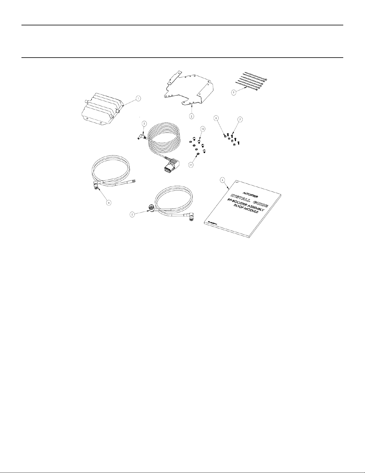
Figure 1-1 Cell Modem Booster Kit Components
T able 1-1 Installation Kit Components (PN: 200-0517-01)
Item Component Part Number
1. RF-BOOSTER 500-0347-02
2. BRACKET,RF-BOOSTER,ROOF MODULE 202-0412-02
3. CABLE ASSY.POWER,ROOF MODULE 201-0468-01
4. CABLE ASSY.RF-BOOST,IN 201-0462-02
2 Cell Booster Kit
Page 9
Cable Diagrams
Item Component Part Number
5. CABLE ASSY. RF-BOOST-OUT 201-0464-02
6. INSTALLATION GUIDE RF-BOOSTER, ROOF MODULE 602-0219-01
7. SCREW,M5x10 FLTHD,PHIL,S.S. 515-0094-01
8. LOCKNUT NYLON INSERT M4 SS 519-0024-01
9. CABLE TIE NYLON 4"x0.10" BLACK 510-0076-01
10. SCREW, M5 x 0.8, PAN,PH,S.S 515-0093-01
11. WASHER,M5, LOCK, EXT TOOTH, M5 517-0024-01
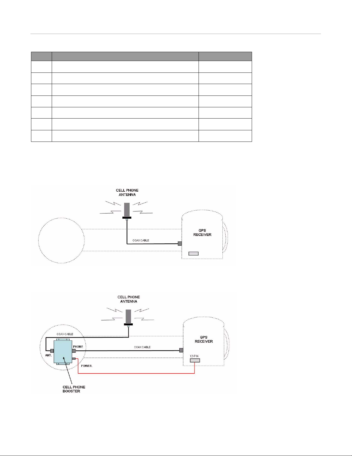
Cable Diagrams
Figure 1-2 shows the roof module and the cable connections to the cell phone antenna before installing the Cell Booster.
Figure 1-2 Cable Diagram Before Booster Installation
Figure 1-3 shows the cable connections to the cell phone antenna after installing the Cell Booster.
Figure 1-3 Cable Diagram
Hardware Installation Manual 3
Page 10

Cable Diagrams
4 Cell Booster Kit
Page 11

Installation Procedure
Cell Modem Booster Installation Procedure
CAUTION
Incorrect installation may damage the Cell Modem Booster
or Cell Phone Modem. Read and understand the instructions
provided in this manual before installing the Cell Modem
Booster.
2
WARNING
Ensure that you are in a stable position on the vehicle
platform when installing or removing the Roof Rail and Roof
Module so you do not fall.
1. The Cell Modem Booster must be installed on the Roof Module on a clean and well illuminated work bench. Remove the
Roof Module from the vehicle and move it to a work bench before starting the installation. Refer to your Hardware
Installation Manual for details on the Roof Module.
2. Clean the Roof Module with a brush to remove dust and loose dirt, and then clean thoroughly with a damp cloth before
starting the installation.
Hardware Installation Manual 5
Page 12

Cell Modem Booster Installation Procedure
3. Remove all the long whip antennas from the roof module and place the roof module upside down on a flat bench. Place a
wood spacer block under the roof module at each end to stabilize the unit and protect the GPS antennas from damage.
Figure 2-1 Bench Setup
4. Remove the two Allen screws and loosen one nut to remove the bracket shown
Figure 2-2 Remove Allen Screws and Nut
6 Cell Booster Kit
Page 13

5. Remove the Phillips screws that attach the cover and remove the cover.
Figure 2-3 Remove Cover
Cell Modem Booster Installation Procedure
6. Install the Cell Booster on the bracket. Secure using the four provided flat head screws and locknuts.
Figure 2-4 Install Cell Booster on Bracket
Hardware Installation Manual 7
Page 14

Cell Modem Booster Installation Procedure
7. Install the bracket with the Cell Booster in the position shown. Secure using four M5 screws and lock washers.
Figure 2-5 Install Cell Booster and Bracket
8. Remove the unused rubber grommet that will be used to route the new Cell Booster cables.
Figure 2-6 Remove Rubber Grommet
8 Cell Booster Kit
Page 15

Cell Modem Booster Installation Procedure
9. Cut the three rubber caps off the grommet using a sharp blade. This reworked grommet will be used for routing the two
coax cables and single power cable for the Cell Booster.
Figure 2-7 Prepare Rubber Grommet
10.Identify the black coax cable that runs from the cell phone antenna (short stubby antenna) to the side of the GPS receiver.
This cable will be totally removed.
Figure 2-8 Identify Cable
Hardware Installation Manual 9
Page 16

Cell Modem Booster Installation Procedure
11. Disconnect the larger coax connector shown (on right) to get access to the cell phone coax cable connector (on left).
Figure 2-9 Disconnect Cable
12. Disconnect the cell phone coax cable shown.
Figure 2-10 Disconnect Cell Phone Coax Cable
10 Cell Booster Kit
Page 17

Cell Modem Booster Installation Procedure
13.Lift the black plastic wear pad that covers the antenna co nnector to gain access to the connector.
Figure 2-11 Remove Wear Pad
14.Disconnect the coax cable connector from the cell phone antenna. Turn the sleeve counterclockwise to loosen.
Figure 2-12 Disconnect Cable from Antenna
Hardware Installation Manual 11
Page 18

Cell Modem Booster Installation Procedure
15. .Figure 2-13 the original cell phone coax cable is shown removed from the roof module. This cable will not be used with
the Cell Booster but it is a good idea to keep it for future use.
Figure 2-13 Removed Cable
16. Route the long coax cable provided in your kit across the roof module. The large connector must be at the Cell Booster end
(left) and the small connector must be at the GPS receiver end (right).
Figure 2-14 Route the Coax Cable
12 Cell Booster Kit
Page 19

Cell Modem Booster Installation Procedure
17.Connect the long coax cable from the ParaDyme GPS receiver to the Cell Booster connector labeled “PHONE”. This cable
will take the cell phone signal from the ParaDyme GPS receiver to the Cell Booster.
Figure 2-15 Connect Long Coax Cable
18.Connect the other end of the cable to the cell phone antenna output connector on the side of the GPS receiver.
Figure 2-16 Connect the Coax Cable
Hardware Installation Manual 13
Page 20

Cell Modem Booster Installation Procedure
Note: Do not tighten this connector now because the cable must rotate freely to allow proper routing at the other end.
19. Reconnect the large coax connector that was previously removed for access.
Figure 2-17 Reconnect Large Coax Cable
20. Remove the dust cap from the auxiliary connector under the GPS receiver.
Figure 2-18 Remove Dust Cap
14 Cell Booster Kit
Page 21

Cell Modem Booster Installation Procedure
21.Connect the Cell Booster 12-pin connector from the power cable to the GPS receiver as shown.
Figure 2-19 Connect Power Cable
22.Route the power cable along the inside of the aluminum extrusion. Secure the cable against other cables using cable ties.
Figure 2-20 Route Power Cable
Hardware Installation Manual 15
Page 22

Cell Modem Booster Installation Procedure
Connect Here
23. Connect the short coax cable from the antenna to the Cell Booster connector labeled “ANTENNA”. This cable will take
the cell phone signal from the Cell Modem Booster to the antenna.
Figure 2-21 Connect Short Coax Cable
24. The aluminum extrusion mu st be separated fro m the Cell Modem Booste r compartment to al low the installati on of the new
cables. While supporting and protecting the GPS antenna, remove the two long screws and separate the extrusion from the
Cell Modem Booster compartment. Reconnect the two parts and insert the screws once all the new cables have been
routed.
Figure 2-22 Remove Screws from Extrusion
16 Cell Booster Kit
Page 23

Cell Modem Booster Installation Procedure
25.Connect the two coax cables and the power cable to the Cell Booster as follows:
• ANT. = Coax towards antenna
• PHONE = Coax towards GPS receiver
• POWER = Power cable
26.Route the cables through the rubber grommet as shown.
Figure 2-23 Route Cables
27.Connect the two coax cable and single power cable to the Cell Booster. Route the cables as shown and secure to the holes
in the bracket using cable ties. Secure the power cable connector along the top of the coax cable using a cable tie.
Figure 2-24 Connect Cables to Cell Booster
Hardware Installation Manual 17
Page 24

Cell Modem Booster Installation Procedure
28. Secure the power cable and coax cable along the extrusion using cable ties. Route the cables so they are in a protected
position away from the edge.
Figure 2-25 Secure Power Cable
29. Install the plastic trim along the extrusion. The plastic trim will keep the cables protected and inside the extrusion.
Figure 2-26 Install Trim
18 Cell Booster Kit
Page 25

Cell Modem Booster Installation Procedure
30.Confirm that all screws and cable connections are tight. Install the cover as shown and secure with the mounting screws.
Figure 2-27 Install Cover
31.Re-install the bracket as shown. Tighten the two Allen screws and nut.
Figure 2-28 Install Bracket
Hardware Installation Manual 19
Page 26

Cell Modem Booster Installation Procedure
32. Tighten all coax cable connector that were previously removed on the GPS receiver.
Figure 2-29 Tighten Connectors
33. Install the whip antennas that were removed. The Cell Modem Booster installation is now complete.
Figure 2-30 Re-Install Antennas
34. Power up the system and test the cell phone communication using the on-screen service menu. Confirm that you have cell
phone coverage.
20 Cell Booster Kit
Page 27

Optional Auxiliary Harness
Optional Auxiliary Harness
1. The Auxiliary Harness is used to connect multiple devices to the roof module such as a USB drive, two serial connections
and 12V devices. The Cell Booster can be powered by the Auxiliary Harness by using an optional Power Adapter cable
(PN: 201-0465-01).
Figure 2-31 Auxiliary Harness (PN: 201-0433-01)
2. Connect the Auxiliary Harness to the 12-pin connector under the GPS receiver.
Figure 2-32 Connect Auxiliary Harness
Hardware Installation Manual 21
Page 28

Optional Auxiliary Harness
3. Route the Auxiliary Harness towards the opposite side of the roof module as shown.
Figure 2-33 Route Harness
4. Connect the 2-pin connector on the Auxiliary Harness to the optional power adapter cable.
Figure 2-34 Connect to Power Cable
5. Feed the mated power connectors into the extrusion as shown.
Figure 2-35 Route Connectors
22 Cell Booster Kit
Page 29

Optional Auxiliary Harness
6. Feed the USB connector into the extrusion as shown. It will remain stored inside the extrusion.
Figure 2-36 Route USB Connector
Note: Confirm that the USB connector is protected by the plastic cap.
7. Route the Auxiliary Harness along the extrusion in a protected position.
Figure 2-37 Route Harness
Hardware Installation Manual 23
Page 30

Optional Auxiliary Harness
8. Secure the cables using cable ties as shown.
Figure 2-38 Secure Cables
9. Secure the Auxiliary Harness to a coax cable as shown using a cable tie.
Figure 2-39 Secure Harness
24 Cell Booster Kit
Page 31

Optional Auxiliary Harness
10.Connect the power adapter cable connector to the Cell Booster and secure with cable ties as previously described. Check
all cable connections and secure all cables before closing the unit.
Figure 2-40 Connect Power Cable
Note: Always install a dust cap over the auxiliary connector when it is not being used.
Hardware Installation Manual 25
Page 32

Optional Auxiliary Harness
26 Cell Booster Kit
 Loading...